EP3254803A1 - Machine for processing section bars - Google Patents
Machine for processing section bars Download PDFInfo
- Publication number
- EP3254803A1 EP3254803A1 EP17174638.1A EP17174638A EP3254803A1 EP 3254803 A1 EP3254803 A1 EP 3254803A1 EP 17174638 A EP17174638 A EP 17174638A EP 3254803 A1 EP3254803 A1 EP 3254803A1
- Authority
- EP
- European Patent Office
- Prior art keywords
- holding
- machine according
- transporting device
- transporting
- base
- Prior art date
- Legal status (The legal status is an assumption and is not a legal conclusion. Google has not performed a legal analysis and makes no representation as to the accuracy of the status listed.)
- Granted
Links
Images


Classifications
-
- B—PERFORMING OPERATIONS; TRANSPORTING
- B23—MACHINE TOOLS; METAL-WORKING NOT OTHERWISE PROVIDED FOR
- B23Q—DETAILS, COMPONENTS, OR ACCESSORIES FOR MACHINE TOOLS, e.g. ARRANGEMENTS FOR COPYING OR CONTROLLING; MACHINE TOOLS IN GENERAL CHARACTERISED BY THE CONSTRUCTION OF PARTICULAR DETAILS OR COMPONENTS; COMBINATIONS OR ASSOCIATIONS OF METAL-WORKING MACHINES, NOT DIRECTED TO A PARTICULAR RESULT
- B23Q7/00—Arrangements for handling work specially combined with or arranged in, or specially adapted for use in connection with, machine tools, e.g. for conveying, loading, positioning, discharging, sorting
- B23Q7/04—Arrangements for handling work specially combined with or arranged in, or specially adapted for use in connection with, machine tools, e.g. for conveying, loading, positioning, discharging, sorting by means of grippers
- B23Q7/041—Arrangements for handling work specially combined with or arranged in, or specially adapted for use in connection with, machine tools, e.g. for conveying, loading, positioning, discharging, sorting by means of grippers step by step
-
- B—PERFORMING OPERATIONS; TRANSPORTING
- B23—MACHINE TOOLS; METAL-WORKING NOT OTHERWISE PROVIDED FOR
- B23Q—DETAILS, COMPONENTS, OR ACCESSORIES FOR MACHINE TOOLS, e.g. ARRANGEMENTS FOR COPYING OR CONTROLLING; MACHINE TOOLS IN GENERAL CHARACTERISED BY THE CONSTRUCTION OF PARTICULAR DETAILS OR COMPONENTS; COMBINATIONS OR ASSOCIATIONS OF METAL-WORKING MACHINES, NOT DIRECTED TO A PARTICULAR RESULT
- B23Q39/00—Metal-working machines incorporating a plurality of sub-assemblies, each capable of performing a metal-working operation
- B23Q39/02—Metal-working machines incorporating a plurality of sub-assemblies, each capable of performing a metal-working operation the sub-assemblies being capable of being brought to act at a single operating station
- B23Q39/021—Metal-working machines incorporating a plurality of sub-assemblies, each capable of performing a metal-working operation the sub-assemblies being capable of being brought to act at a single operating station with a plurality of toolheads per workholder, whereby the toolhead is a main spindle, a multispindle, a revolver or the like
- B23Q39/025—Metal-working machines incorporating a plurality of sub-assemblies, each capable of performing a metal-working operation the sub-assemblies being capable of being brought to act at a single operating station with a plurality of toolheads per workholder, whereby the toolhead is a main spindle, a multispindle, a revolver or the like with different working directions of toolheads on same workholder
- B23Q39/026—Metal-working machines incorporating a plurality of sub-assemblies, each capable of performing a metal-working operation the sub-assemblies being capable of being brought to act at a single operating station with a plurality of toolheads per workholder, whereby the toolhead is a main spindle, a multispindle, a revolver or the like with different working directions of toolheads on same workholder simultaneous working of toolheads
-
- B—PERFORMING OPERATIONS; TRANSPORTING
- B23—MACHINE TOOLS; METAL-WORKING NOT OTHERWISE PROVIDED FOR
- B23Q—DETAILS, COMPONENTS, OR ACCESSORIES FOR MACHINE TOOLS, e.g. ARRANGEMENTS FOR COPYING OR CONTROLLING; MACHINE TOOLS IN GENERAL CHARACTERISED BY THE CONSTRUCTION OF PARTICULAR DETAILS OR COMPONENTS; COMBINATIONS OR ASSOCIATIONS OF METAL-WORKING MACHINES, NOT DIRECTED TO A PARTICULAR RESULT
- B23Q2240/00—Machine tools specially suited for a specific kind of workpiece
- B23Q2240/007—Elongated workpieces
-
- B—PERFORMING OPERATIONS; TRANSPORTING
- B27—WORKING OR PRESERVING WOOD OR SIMILAR MATERIAL; NAILING OR STAPLING MACHINES IN GENERAL
- B27M—WORKING OF WOOD NOT PROVIDED FOR IN SUBCLASSES B27B - B27L; MANUFACTURE OF SPECIFIC WOODEN ARTICLES
- B27M1/00—Working of wood not provided for in subclasses B27B - B27L, e.g. by stretching
- B27M1/08—Working of wood not provided for in subclasses B27B - B27L, e.g. by stretching by multi-step processes
Definitions
- the present invention relates to a machine for processing section bars.
- section bar processing field in particular for section bars made of aluminium, light alloys, PVC or the like, it is known to provide a machine of the type comprising an elongated base; at least one processing station mounted along the base; and a feeding unit designed to hold the section bar at one rear end thereof and feed it along the base and through the processing station.
- the processing station is provided with a cutting device for cutting the section bar into two pieces, and an operating head for performing milling and/or drilling operations in said pieces.
- the section bar and the pieces are normally held by at least two clamping vices mounted in the area of the processing station and movable along the base.
- the clamping vices used to hold the section bars during the processing by the cutting device and the operating head are generally of two types.
- each clamping vice is moved along the base by a respective motor.
- the machine is relatively expensive because of the presence of a motor for the feeding unit and a motor for each clamping vice and is relatively complex because of the need to interconnect and synchronize the three motors with each other so as to move the feeding unit and the two clamping vices with respective identical laws of motion.
- one clamping vice is motorised and the other clamping vice is a non-motorised clamping vice dragged along the base by the section bar which, once tightened in the two clamping vices, makes said clamping vices integral with each other.
- the lubricating oil deposited on the section bar during the processing by the cutting device and the operating head can cause slippage of the section bar with respect to the non-motorised clamping vice and compromise the correct synchronization of the two clamping vices.
- the object of the present invention is to provide a machine for processing section bars, which is free from the drawbacks described above and simple and economical to implement.
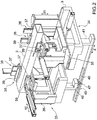
- number 1 indicates, as a whole, a machine for processing section bars 2, in particular made of aluminium, light alloys, PVC or the like, having an elongated shape.
- the machine 1 comprises an elongated base 3, which extends in a horizontal direction 4, and is provided with a longitudinal guide side-member 5 parallel to said direction 4.
- the machine 1 also comprises two roller support devices 6, 7 mounted in succession along the base 3.
- Each device 6, 7 has a plurality of rollers 8, which are mounted to rotate about respective rotation axes 9 substantially parallel to each other and to a horizontal direction 10 transverse to direction 4, and define a support plane P for at least one bar 2.
- Each roller 8 is movable in a vertical direction 11 orthogonal to directions 4 and 10 between a raised operative position and a lowered rest position.
- the machine 1 is also provided with a loading station 12 for loading the bars 2 to be processed onto the device 6, and an unloading station 13 for unloading the bars 2 just processed from the device 7.
- Each station 12, 13 comprises a belt conveyor 14, which faces the respective device 6, 7 in direction 10, and comprises, in turn, a plurality of conveyor belts 15, which are parallel to each other and to said direction 10.
- the machine 1 further comprises a processing station 16, which is formed along the base 3 between the stations 12, 13, and extends between the devices 6, 7.
- the section bars 2 are fed along the plane P and through the station 16 in direction 4 by a feeding device 17 comprising a first horizontal slide 18 coupled to the side-member 5 in a sliding manner so as to perform, with respect to the base 3, straight movements along the side-member 5 in direction 4; a second horizontal slide 19 coupled to the horizontal slide 18 in a sliding manner so as to perform, with respect to the horizontal slide 18, straight movements in direction 10; and a vertical slide 20 coupled to the horizontal slide 19 in a sliding manner so as to perform, with respect to the horizontal slide 19, straight movements in direction 11.
- a feeding device 17 comprising a first horizontal slide 18 coupled to the side-member 5 in a sliding manner so as to perform, with respect to the base 3, straight movements along the side-member 5 in direction 4; a second horizontal slide 19 coupled to the horizontal slide 18 in a sliding manner so as to perform, with respect to the horizontal slide 18, straight movements in direction 10; and a vertical slide 20 coupled to the horizontal slide 19 in a sliding manner so as to perform, with respect to the horizontal slide 19, straight movements in direction
- the vertical slide 20 has an elongated shape, extends in direction 4, and supports a holding member 21 connected to a free end of said vertical slide 20.
- the member 21 is rotatably coupled to the vertical slide 20 so as to rotate, with respect to the vertical slide 20, about a rotation axis (not shown) parallel to direction 4, and comprises two jaws (not shown) that are movable between a clamping position and a release position of the section bars 2.
- the station 16 is provided with a milling assembly 22 comprising an annular frame 23, which is mounted between the stations 12, 13, and extends around a path A along which the section bars 2 are fed; and a plurality of tool-holding spindles 24, which are mounted parallel to directions 10 and 11, and are each adapted to receive and hold a respective milling tool U of the known type.
- the spindles 24 are mounted on the frame 23 via the interposition of a cross slide 25, which has an annular shape, extends around the path A, and is shaped so as to allow the spindles 24 to move, with respect to the base 3, in directions 10 and 11.
- the spindles 24 parallel to direction 10 (hereinafter referred to as 24a) are coupled to the cross slide 25 so as to move, with respect to the cross slide 25, independently from one another in direction 10; and the spindles 24 parallel to direction 11 (hereinafter referred to as 24b) are coupled to the cross slide 25 so as to move, with respect to the cross slide 25, independently from one another in direction 11.
- the station 16 is also provided with an overhead crane 26, which is mounted between the milling assembly 22 and the station 13, and is movable, with respect to the base 3, between the devices 6, 7 and the stations 12, 13 in direction 4.
- the overhead crane 26 comprises a horizontal crossbar 27, which extends above the plane P in direction 10, supports a cutting device 28 for cutting each section bar 2 into two pieces (not shown), and further supports a drilling and/or milling device 29 for drilling into the adjacent ends of said pieces (not shown).
- the device 28 is provided with a circular cutting blade 30, which is mounted to rotate about its own longitudinal axis, and is movable, with respect to the crossbar 27, in directions 10 and 11 and about a rotation axis 31 parallel to direction 11.
- the device 29 is provided with a drilling and/or milling head 32 that is movable, with respect to the crossbar 27, in directions 10 and 11.
- the station 16 is provided, in this case, with two holding devices 33, 34 that are movable along the base 3 in direction 4.
- the two devices 33, 34 are arranged on opposite sides of the spindles 24a, 24b in direction 4, both when the tools U have respective rotation axes C coplanar with a single vertical containment plane P perpendicular to direction 4 ( Figure 5 ), and when the axes C are arranged in and/or between two parallel containment planes P1, P2 separate from one another and perpendicular to said direction 4 ( Figure 6 ).
- the device 34 is mounted between the spindles 24a, 24b and the overhead crane 26.
- Each device 33, 34 comprises a slide 35, which is coupled to the base 3 in a sliding manner so as to perform, with respect to the base 3, straight movements in direction 4, and supports a horizontal clamping vice 36 comprising two jaws 37 perpendicular to direction 10 and movable with respect to each other in said direction 10 between a clamping position and a release position of at least one section bar 2.
- Each slide 35 also supports a vertical clamping vice 38 comprising two jaws 39 perpendicular to direction 11 and movable with respect to each other in said direction 11 between a clamping position and a release position of at least one section bar 2.
- the device 34 is a non-motorised device, and is provided with a guide track 40, which extends between the devices 33, 34 parallel to direction 4, and is fixed to a free end of a vertical upright 41 projecting downwards from the respective slide 35 in direction 11.
- the track 40 extends through the frame 23 and the cross slide 25 or below the frame 23 and the cross slide 25.
- the device 33 is motorised and is moved along the base 3 in direction 4 by an operating device 42 comprising an electric motor 43, which is mounted on the respective slide 35, and has an output shaft provided with a gear (not shown) coupled to a rack 44 fixed along the base 3 parallel to said direction 4.
- an operating device 42 comprising an electric motor 43, which is mounted on the respective slide 35, and has an output shaft provided with a gear (not shown) coupled to a rack 44 fixed along the base 3 parallel to said direction 4.
- the device 33 is also provided with a shoe 45, which is formed on the free end of a vertical upright 46 projecting downwards from the respective slide 35 in direction 11, and is coupled to the track 40 in a sliding manner.
- the shoe 45 houses, on the inside, a device 47 for locking the device 33 along the track 40.
- the device 47 comprises two clamping jaws 48, which are arranged on the opposite side of the track 40 in direction 10, and are movable between a clamping position and a release position of said track 40.
- the devices 33, 34 are integral with each other and are fed along the base 3 in direction 4 solely under the thrust of the operating device 42.
- the device 33 can be fed by the device 42 along the base 3 in direction 4, while the device 34 remains stationary or is moved in the direction of the station 12 by a defined pushing device, in this case by an actuator cylinder 49 fixed to the base 3 parallel to direction 4 and provided with an output shaft 50 oriented towards the station 12 and adapted to contact the slide 35 of the said device 34.
Landscapes
- Engineering & Computer Science (AREA)
- Mechanical Engineering (AREA)
- Sawing (AREA)
- Jigs For Machine Tools (AREA)
- Circuits Of Receivers In General (AREA)
- Paper (AREA)
- Threshing Machine Elements (AREA)
Abstract
Description
- The present invention relates to a machine for processing section bars.
- In the section bar processing field, in particular for section bars made of aluminium, light alloys, PVC or the like, it is known to provide a machine of the type comprising an elongated base; at least one processing station mounted along the base; and a feeding unit designed to hold the section bar at one rear end thereof and feed it along the base and through the processing station.
- Generally, the processing station is provided with a cutting device for cutting the section bar into two pieces, and an operating head for performing milling and/or drilling operations in said pieces.
- During the processing by the cutting device and the operating head, the section bar and the pieces are normally held by at least two clamping vices mounted in the area of the processing station and movable along the base.
- The clamping vices used to hold the section bars during the processing by the cutting device and the operating head are generally of two types.
- According to a first type, each clamping vice is moved along the base by a respective motor. In this case, the machine is relatively expensive because of the presence of a motor for the feeding unit and a motor for each clamping vice and is relatively complex because of the need to interconnect and synchronize the three motors with each other so as to move the feeding unit and the two clamping vices with respective identical laws of motion.
- According to the other of the two known types mentioned above, one clamping vice is motorised and the other clamping vice is a non-motorised clamping vice dragged along the base by the section bar which, once tightened in the two clamping vices, makes said clamping vices integral with each other. In this case, the lubricating oil deposited on the section bar during the processing by the cutting device and the operating head can cause slippage of the section bar with respect to the non-motorised clamping vice and compromise the correct synchronization of the two clamping vices.
- The object of the present invention is to provide a machine for processing section bars, which is free from the drawbacks described above and simple and economical to implement.
- According to the present invention, a machine for processing section bars is provided as claimed in the appended claims.
- The present invention will now be described with reference to the accompanying drawings, which illustrate a non-limiting embodiment thereof, in which:
-
Figure 1 is a schematic perspective view, with parts removed for clarity, of a preferred embodiment of the machine for processing section bars of the present invention; -
Figure 2 is a schematic perspective view, with parts removed for clarity, of a first detail of the machine inFigure 1 ; -
Figure 3 is a schematic side view, with parts enlarged and parts removed for clarity, of the detail inFigure 2 ; -
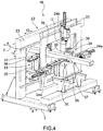
Figure 4 is a schematic perspective view, with parts removed for clarity, of a second detail of the machine inFigure 1 ; -
Figure 5 is a schematic side view, with parts removed for clarity, of the detail ofFigure 4 ; and -
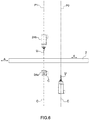
Figure 6 is a schematic side view, with parts removed for clarity, of a variant of the detail ofFigures 4 and5 . - With reference to
Figure 1 , number 1 indicates, as a whole, a machine forprocessing section bars 2, in particular made of aluminium, light alloys, PVC or the like, having an elongated shape. - The machine 1 comprises an
elongated base 3, which extends in ahorizontal direction 4, and is provided with a longitudinal guide side-member 5 parallel to saiddirection 4. - The machine 1 also comprises two
roller support devices base 3. Eachdevice rollers 8, which are mounted to rotate aboutrespective rotation axes 9 substantially parallel to each other and to ahorizontal direction 10 transverse todirection 4, and define a support plane P for at least onebar 2. - Each
roller 8 is movable in avertical direction 11 orthogonal todirections - The machine 1 is also provided with a
loading station 12 for loading thebars 2 to be processed onto thedevice 6, and anunloading station 13 for unloading thebars 2 just processed from thedevice 7. - Each
station belt conveyor 14, which faces therespective device direction 10, and comprises, in turn, a plurality ofconveyor belts 15, which are parallel to each other and to saiddirection 10. - The machine 1 further comprises a
processing station 16, which is formed along thebase 3 between thestations devices - The
section bars 2 are fed along the plane P and through thestation 16 indirection 4 by afeeding device 17 comprising a firsthorizontal slide 18 coupled to the side-member 5 in a sliding manner so as to perform, with respect to thebase 3, straight movements along the side-member 5 indirection 4; a secondhorizontal slide 19 coupled to thehorizontal slide 18 in a sliding manner so as to perform, with respect to thehorizontal slide 18, straight movements indirection 10; and avertical slide 20 coupled to thehorizontal slide 19 in a sliding manner so as to perform, with respect to thehorizontal slide 19, straight movements indirection 11. - The
vertical slide 20 has an elongated shape, extends indirection 4, and supports aholding member 21 connected to a free end of saidvertical slide 20. - The
member 21 is rotatably coupled to thevertical slide 20 so as to rotate, with respect to thevertical slide 20, about a rotation axis (not shown) parallel todirection 4, and comprises two jaws (not shown) that are movable between a clamping position and a release position of thesection bars 2. - The
station 16 is provided with amilling assembly 22 comprising anannular frame 23, which is mounted between thestations section bars 2 are fed; and a plurality of tool-holding spindles 24, which are mounted parallel todirections - The spindles 24 are mounted on the
frame 23 via the interposition of across slide 25, which has an annular shape, extends around the path A, and is shaped so as to allow the spindles 24 to move, with respect to thebase 3, indirections - The spindles 24 parallel to direction 10 (hereinafter referred to as 24a) are coupled to the
cross slide 25 so as to move, with respect to thecross slide 25, independently from one another indirection 10; and the spindles 24 parallel to direction 11 (hereinafter referred to as 24b) are coupled to thecross slide 25 so as to move, with respect to thecross slide 25, independently from one another indirection 11. - The
station 16 is also provided with anoverhead crane 26, which is mounted between themilling assembly 22 and thestation 13, and is movable, with respect to thebase 3, between thedevices stations direction 4. - The
overhead crane 26 comprises ahorizontal crossbar 27, which extends above the plane P indirection 10, supports acutting device 28 for cutting eachsection bar 2 into two pieces (not shown), and further supports a drilling and/ormilling device 29 for drilling into the adjacent ends of said pieces (not shown). - The
device 28 is provided with acircular cutting blade 30, which is mounted to rotate about its own longitudinal axis, and is movable, with respect to thecrossbar 27, indirections rotation axis 31 parallel todirection 11. - The
device 29 is provided with a drilling and/ormilling head 32 that is movable, with respect to thecrossbar 27, indirections - As illustrated in
Figures 2 ,3 ,4 ,5 , and6 , thestation 16 is provided, in this case, with twoholding devices base 3 indirection 4. - The two
devices spindles direction 4, both when the tools U have respective rotation axes C coplanar with a single vertical containment plane P perpendicular to direction 4 (Figure 5 ), and when the axes C are arranged in and/or between two parallel containment planes P1, P2 separate from one another and perpendicular to said direction 4 (Figure 6 ). - The
device 34 is mounted between thespindles overhead crane 26. - Each
device slide 35, which is coupled to thebase 3 in a sliding manner so as to perform, with respect to thebase 3, straight movements indirection 4, and supports ahorizontal clamping vice 36 comprising twojaws 37 perpendicular todirection 10 and movable with respect to each other in saiddirection 10 between a clamping position and a release position of at least onesection bar 2. - Each
slide 35 also supports avertical clamping vice 38 comprising twojaws 39 perpendicular todirection 11 and movable with respect to each other in saiddirection 11 between a clamping position and a release position of at least onesection bar 2. - The
device 34 is a non-motorised device, and is provided with aguide track 40, which extends between thedevices direction 4, and is fixed to a free end of a vertical upright 41 projecting downwards from therespective slide 35 indirection 11. - The
track 40 extends through theframe 23 and the cross slide 25 or below theframe 23 and thecross slide 25. - The
device 33 is motorised and is moved along thebase 3 indirection 4 by anoperating device 42 comprising anelectric motor 43, which is mounted on therespective slide 35, and has an output shaft provided with a gear (not shown) coupled to arack 44 fixed along thebase 3 parallel to saiddirection 4. - The
device 33 is also provided with ashoe 45, which is formed on the free end of a vertical upright 46 projecting downwards from therespective slide 35 indirection 11, and is coupled to thetrack 40 in a sliding manner. - The
shoe 45 houses, on the inside, adevice 47 for locking thedevice 33 along thetrack 40. - The
device 47 comprises twoclamping jaws 48, which are arranged on the opposite side of thetrack 40 indirection 10, and are movable between a clamping position and a release position of saidtrack 40. - When the
jaws 48 are moved into the clamping position, thedevices base 3 indirection 4 solely under the thrust of theoperating device 42. - When the
jaws 48 are moved into the release position, thedevice 33 can be fed by thedevice 42 along thebase 3 indirection 4, while thedevice 34 remains stationary or is moved in the direction of thestation 12 by a defined pushing device, in this case by anactuator cylinder 49 fixed to thebase 3 parallel todirection 4 and provided with an output shaft 50 oriented towards thestation 12 and adapted to contact theslide 35 of thesaid device 34.
Claims (12)
- A machine for processing section bars (2), in particular made of aluminium, light alloys, PVC or the like, comprising an elongated base (3) extending in a first direction (4); at least one processing station (16); and a feeding unit (17, 33, 34) to feed the section bars (2) through the processing station (16) in the first direction (4); the processing station (16) being provided with a milling assembly (22) comprising, in turn, a support frame (23, 25) extending around a path (A) along which the section bars (2) are fed, and a plurality of tool-holding spindles (24), which are mounted on the support frame (23) parallel to a second and/or a third direction (10, 11) orthogonal to one another and to the first direction (4), and are provided with respective tools (U) for processing at least one section bar (2); the feeding unit (17, 33, 34) comprising a first holding and transporting device (33), an operating device (42) to move the first holding and transporting device (33) along the base (3) in the first direction (4), and a second holding and transporting device (34), which is aligned with the first holding and transporting device (33) along the first direction (4), and is movable along the base (3) in said first direction (4); said first and second transporting devices (33, 34) being arranged on opposite sides of the tool-holding spindles (24) in the first direction (4); and characterised in that it comprises, furthermore, a locking device (47) to lock the second holding and transporting device (34) on the first holding and transporting device (33) and feed both holding and transporting devices (33, 34) along the base (3) in the first direction (4) under the thrust of said operating device (42).
- The machine according to claim 1, wherein the locking device (47) is movable between a locking position, in which it locks the second holding and transporting device (34) on the first holding and transporting device (33), and a release position.
- The machine according to claim 1 or 2, wherein said first and second holding and transporting devices (33, 34) are coupled to the base (3) in a sliding manner.
- The machine according to any one of the preceding claims, wherein the first holding and transporting device (33) is coupled, in a sliding manner, to a guide track (40), which is integral with the second holding and transporting device (34).
- The machine according to claim 4, wherein the locking device (47) is movable between a locking position, in which it locks the first holding and transporting device (33) on the guide track (40), and a release position.
- The machine according to any one of the preceding claims, wherein each one of said first and second holding and transporting devices (33, 34) comprises at least one clamping vice (36, 38) provided with two jaws (37, 39), which are movable between a clamping position and a release position of the section bar (2).
- The machine according to any one of the preceding claims, wherein said first and second holding and transporting devices (33, 34) are mounted in the area of the processing station (16).
- The machine according to any one of the preceding claims, wherein the feeding unit (17, 33, 34) comprises, furthermore, a third holding and transporting device (17), which is designed to hold the section bar (2) at one rear end thereof.
- The machine according to any one of the preceding claims and comprising, furthermore, a loading station (12) to load the section bars (2) to be processed and an unloading station (13) to unload the section bars (2) that have just been processed; the processing station (16) being arranged between the loading station (12) and the unloading station (13).
- The machine according to claim 9 and comprising, furthermore, a pushing device (49) to move the second holding and transporting device (34) along the base (3) towards the loading station (12), when the locking device (47) is in its release position.
- The machine according to any one of the preceding claims, wherein the processing station (16) is also provided with a cutting device (28) for cutting each section bar (2) into two pieces.
- The machine according to any one of the preceding claims, wherein the support frame (23, 25) is annular.
Applications Claiming Priority (1)
| Application Number | Priority Date | Filing Date | Title |
|---|---|---|---|
| ITUA2016A004117A ITUA20164117A1 (en) | 2016-06-06 | 2016-06-06 | MACHINE FOR PROFILE PROCESSING |
Publications (2)
| Publication Number | Publication Date |
|---|---|
| EP3254803A1 true EP3254803A1 (en) | 2017-12-13 |
| EP3254803B1 EP3254803B1 (en) | 2019-05-08 |
Family
ID=57113573
Family Applications (1)
| Application Number | Title | Priority Date | Filing Date |
|---|---|---|---|
| EP17174638.1A Active EP3254803B1 (en) | 2016-06-06 | 2017-06-06 | Machine for processing section bars |
Country Status (2)
| Country | Link |
|---|---|
| EP (1) | EP3254803B1 (en) |
| IT (1) | ITUA20164117A1 (en) |
Cited By (8)
| Publication number | Priority date | Publication date | Assignee | Title |
|---|---|---|---|---|
| FR3070019A1 (en) * | 2017-08-08 | 2019-02-15 | F.O.M. Industrie S.R.L. | MACHINE FOR MACHINING BARS OF ALUMINUM, LIGHT ALLOYS, PVC OR SIMILAR. |
| IT201800002555A1 (en) * | 2018-02-09 | 2019-08-09 | Manni Sipre S P A | APPARATUS FOR PROCESSING STRUCTURAL STEEL PRODUCTS INCLUDING AN ACOUSTICALLY INSULATING COVER |
| EP3533571A1 (en) * | 2018-03-01 | 2019-09-04 | BIESSE S.p.A. | A machine for cutting panels made of wood or the like |
| IT201800020092A1 (en) * | 2018-12-18 | 2020-06-18 | Scm Group Spa | Plant for squaring, edging and drilling wooden pieces and the like, and relative operating method. |
| IT201900019550A1 (en) * | 2019-10-22 | 2021-04-22 | Mecal Machinery S R L | Loading and unloading unit for profiles |
| CN112975491A (en) * | 2021-02-25 | 2021-06-18 | 上海城建职业学院 | Drainage pipeline processingequipment |
| IT202000011542A1 (en) * | 2020-05-19 | 2021-11-19 | F O M Ind S R L | MACHINE FOR PROCESSING PROFILES, IN PARTICULAR ALUMINUM, LIGHT ALLOYS, PVC OR SIMILAR |
| EP4007669A4 (en) * | 2019-08-02 | 2022-08-31 | Schtec Makine Sanayi ve Ticaret Anonim Sirketi | A profile processing machine having processing and cutting units |
Citations (2)
| Publication number | Priority date | Publication date | Assignee | Title |
|---|---|---|---|---|
| EP2392439A1 (en) * | 2010-05-27 | 2011-12-07 | Biesse S.p.A. | Method and machine for machining components made of wood or the like, in particular components for door and window frames |
| EP2540429A1 (en) * | 2011-07-01 | 2013-01-02 | BIESSE S.p.A. | A cutting machine for cutting wood panels or alike |
-
2016
- 2016-06-06 IT ITUA2016A004117A patent/ITUA20164117A1/en unknown
-
2017
- 2017-06-06 EP EP17174638.1A patent/EP3254803B1/en active Active
Patent Citations (2)
| Publication number | Priority date | Publication date | Assignee | Title |
|---|---|---|---|---|
| EP2392439A1 (en) * | 2010-05-27 | 2011-12-07 | Biesse S.p.A. | Method and machine for machining components made of wood or the like, in particular components for door and window frames |
| EP2540429A1 (en) * | 2011-07-01 | 2013-01-02 | BIESSE S.p.A. | A cutting machine for cutting wood panels or alike |
Cited By (13)
| Publication number | Priority date | Publication date | Assignee | Title |
|---|---|---|---|---|
| FR3070019A1 (en) * | 2017-08-08 | 2019-02-15 | F.O.M. Industrie S.R.L. | MACHINE FOR MACHINING BARS OF ALUMINUM, LIGHT ALLOYS, PVC OR SIMILAR. |
| IT201800002555A1 (en) * | 2018-02-09 | 2019-08-09 | Manni Sipre S P A | APPARATUS FOR PROCESSING STRUCTURAL STEEL PRODUCTS INCLUDING AN ACOUSTICALLY INSULATING COVER |
| EP3524387A1 (en) * | 2018-02-09 | 2019-08-14 | Manni Sipre S.p.A. | Apparatus for processing structural steel products comprising an acoustically insulating cover |
| EP3533571A1 (en) * | 2018-03-01 | 2019-09-04 | BIESSE S.p.A. | A machine for cutting panels made of wood or the like |
| IT201800020092A1 (en) * | 2018-12-18 | 2020-06-18 | Scm Group Spa | Plant for squaring, edging and drilling wooden pieces and the like, and relative operating method. |
| EP4007669A4 (en) * | 2019-08-02 | 2022-08-31 | Schtec Makine Sanayi ve Ticaret Anonim Sirketi | A profile processing machine having processing and cutting units |
| EP3812088A1 (en) * | 2019-10-22 | 2021-04-28 | Mecal Machinery S.r.l. | Loading/unloading unit for profiles |
| IT201900019550A1 (en) * | 2019-10-22 | 2021-04-22 | Mecal Machinery S R L | Loading and unloading unit for profiles |
| US12012298B2 (en) | 2019-10-22 | 2024-06-18 | Mecal Machinery S.R.L. | Loading/unloading units for profiles |
| IT202000011542A1 (en) * | 2020-05-19 | 2021-11-19 | F O M Ind S R L | MACHINE FOR PROCESSING PROFILES, IN PARTICULAR ALUMINUM, LIGHT ALLOYS, PVC OR SIMILAR |
| EP3912757A1 (en) * | 2020-05-19 | 2021-11-24 | F.O.M. Industrie S.r.l. | Machine to process section bars, in particular made of aluminium, light alloys, pvc or the like |
| CN112975491A (en) * | 2021-02-25 | 2021-06-18 | 上海城建职业学院 | Drainage pipeline processingequipment |
| CN112975491B (en) * | 2021-02-25 | 2022-03-01 | 上海城建职业学院 | Drainage pipeline processingequipment |
Also Published As
| Publication number | Publication date |
|---|---|
| ITUA20164117A1 (en) | 2017-12-06 |
| EP3254803B1 (en) | 2019-05-08 |
Similar Documents
| Publication | Publication Date | Title |
|---|---|---|
| EP3254803B1 (en) | Machine for processing section bars | |
| EP3260234B1 (en) | Machine to process section bars | |
| EP2842705B1 (en) | Method to process wood components or the like | |
| EP2366480B1 (en) | An apparatus for machining door or window frames | |
| US20180257188A1 (en) | Gantry type conveying device and processing line | |
| KR102319343B1 (en) | Apparatus for carrying pallet | |
| JP7352816B2 (en) | Transport equipment and machine tools | |
| EP2415571B1 (en) | Machine for machining wooden frames or similar | |
| EP3769907B1 (en) | Machine to process section bars made of aluminium, light alloys, pvc or the like | |
| ITBO20120241A1 (en) | METHOD AND MACHINE FOR PROCESSING WOOD OR SIMILAR COMPONENTS | |
| EP3636386B1 (en) | Work centre to process section bars made of aluminium light alloys pvc or the like | |
| TW201742807A (en) | Transport device with gripping tongs | |
| JP5484382B2 (en) | Work transfer device | |
| EP2098344B2 (en) | Method and machine for machining wood components or the like | |
| EP3175950B1 (en) | Machine to process bars made of aluminium, light alloys, pvc or the like | |
| EP3636383B1 (en) | Work centre to process section bars made of aluminium light alloys pvc or the like | |
| EP3868512B1 (en) | A method and machine to process section bars, in particular made of aluminium, light alloys, pvc or the like | |
| EP1250213B1 (en) | Machine tool and method for working elongated elements, in particular metallic profiled elements | |
| CN109248965A (en) | A kind of three axis punching press feeding mechanical hands | |
| EP3167969B1 (en) | Machine to process bars made of aluminium, light alloys, pvc or the like | |
| EP3950218A1 (en) | Work centre to process section bars, in particular made of aluminium, light alloys, pvc or the like | |
| EP2210723A1 (en) | Machine and method for work wood or similar material | |
| JP6071753B2 (en) | Long work loading method, long work loading apparatus, and long work processing apparatus | |
| EP4275837A1 (en) | Method and work centre to process section bars, in particular made of aluminium, light alloys, pvc or the like | |
| CN210305303U (en) | Automatic hub machining system |
Legal Events
| Date | Code | Title | Description |
|---|---|---|---|
| PUAI | Public reference made under article 153(3) epc to a published international application that has entered the european phase |
Free format text: ORIGINAL CODE: 0009012 |
|
| STAA | Information on the status of an ep patent application or granted ep patent |
Free format text: STATUS: THE APPLICATION HAS BEEN PUBLISHED |
|
| AK | Designated contracting states |
Kind code of ref document: A1 Designated state(s): AL AT BE BG CH CY CZ DE DK EE ES FI FR GB GR HR HU IE IS IT LI LT LU LV MC MK MT NL NO PL PT RO RS SE SI SK SM TR |
|
| AX | Request for extension of the european patent |
Extension state: BA ME |
|
| STAA | Information on the status of an ep patent application or granted ep patent |
Free format text: STATUS: REQUEST FOR EXAMINATION WAS MADE |
|
| 17P | Request for examination filed |
Effective date: 20180612 |
|
| RBV | Designated contracting states (corrected) |
Designated state(s): AL AT BE BG CH CY CZ DE DK EE ES FI FR GB GR HR HU IE IS IT LI LT LU LV MC MK MT NL NO PL PT RO RS SE SI SK SM TR |
|
| GRAJ | Information related to disapproval of communication of intention to grant by the applicant or resumption of examination proceedings by the epo deleted |
Free format text: ORIGINAL CODE: EPIDOSDIGR1 |
|
| GRAP | Despatch of communication of intention to grant a patent |
Free format text: ORIGINAL CODE: EPIDOSNIGR1 |
|
| GRAP | Despatch of communication of intention to grant a patent |
Free format text: ORIGINAL CODE: EPIDOSNIGR1 |
|
| STAA | Information on the status of an ep patent application or granted ep patent |
Free format text: STATUS: GRANT OF PATENT IS INTENDED |
|
| INTG | Intention to grant announced |
Effective date: 20181122 |
|
| GRAS | Grant fee paid |
Free format text: ORIGINAL CODE: EPIDOSNIGR3 |
|
| GRAA | (expected) grant |
Free format text: ORIGINAL CODE: 0009210 |
|
| STAA | Information on the status of an ep patent application or granted ep patent |
Free format text: STATUS: THE PATENT HAS BEEN GRANTED |
|
| AK | Designated contracting states |
Kind code of ref document: B1 Designated state(s): AL AT BE BG CH CY CZ DE DK EE ES FI FR GB GR HR HU IE IS IT LI LT LU LV MC MK MT NL NO PL PT RO RS SE SI SK SM TR |
|
| REG | Reference to a national code |
Ref country code: GB Ref legal event code: FG4D |
|
| REG | Reference to a national code |
Ref country code: CH Ref legal event code: EP Ref country code: AT Ref legal event code: REF Ref document number: 1129440 Country of ref document: AT Kind code of ref document: T Effective date: 20190515 |
|
| REG | Reference to a national code |
Ref country code: DE Ref legal event code: R096 Ref document number: 602017003785 Country of ref document: DE |
|
| REG | Reference to a national code |
Ref country code: IE Ref legal event code: FG4D |
|
| REG | Reference to a national code |
Ref country code: NL Ref legal event code: MP Effective date: 20190508 |
|
| REG | Reference to a national code |
Ref country code: LT Ref legal event code: MG4D |
|
| PG25 | Lapsed in a contracting state [announced via postgrant information from national office to epo] |
Ref country code: FI Free format text: LAPSE BECAUSE OF FAILURE TO SUBMIT A TRANSLATION OF THE DESCRIPTION OR TO PAY THE FEE WITHIN THE PRESCRIBED TIME-LIMIT Effective date: 20190508 Ref country code: NO Free format text: LAPSE BECAUSE OF FAILURE TO SUBMIT A TRANSLATION OF THE DESCRIPTION OR TO PAY THE FEE WITHIN THE PRESCRIBED TIME-LIMIT Effective date: 20190808 Ref country code: AL Free format text: LAPSE BECAUSE OF FAILURE TO SUBMIT A TRANSLATION OF THE DESCRIPTION OR TO PAY THE FEE WITHIN THE PRESCRIBED TIME-LIMIT Effective date: 20190508 Ref country code: PT Free format text: LAPSE BECAUSE OF FAILURE TO SUBMIT A TRANSLATION OF THE DESCRIPTION OR TO PAY THE FEE WITHIN THE PRESCRIBED TIME-LIMIT Effective date: 20190908 Ref country code: SE Free format text: LAPSE BECAUSE OF FAILURE TO SUBMIT A TRANSLATION OF THE DESCRIPTION OR TO PAY THE FEE WITHIN THE PRESCRIBED TIME-LIMIT Effective date: 20190508 Ref country code: NL Free format text: LAPSE BECAUSE OF FAILURE TO SUBMIT A TRANSLATION OF THE DESCRIPTION OR TO PAY THE FEE WITHIN THE PRESCRIBED TIME-LIMIT Effective date: 20190508 Ref country code: HR Free format text: LAPSE BECAUSE OF FAILURE TO SUBMIT A TRANSLATION OF THE DESCRIPTION OR TO PAY THE FEE WITHIN THE PRESCRIBED TIME-LIMIT Effective date: 20190508 Ref country code: LT Free format text: LAPSE BECAUSE OF FAILURE TO SUBMIT A TRANSLATION OF THE DESCRIPTION OR TO PAY THE FEE WITHIN THE PRESCRIBED TIME-LIMIT Effective date: 20190508 Ref country code: ES Free format text: LAPSE BECAUSE OF FAILURE TO SUBMIT A TRANSLATION OF THE DESCRIPTION OR TO PAY THE FEE WITHIN THE PRESCRIBED TIME-LIMIT Effective date: 20190508 |
|
| PG25 | Lapsed in a contracting state [announced via postgrant information from national office to epo] |
Ref country code: BG Free format text: LAPSE BECAUSE OF FAILURE TO SUBMIT A TRANSLATION OF THE DESCRIPTION OR TO PAY THE FEE WITHIN THE PRESCRIBED TIME-LIMIT Effective date: 20190808 Ref country code: RS Free format text: LAPSE BECAUSE OF FAILURE TO SUBMIT A TRANSLATION OF THE DESCRIPTION OR TO PAY THE FEE WITHIN THE PRESCRIBED TIME-LIMIT Effective date: 20190508 Ref country code: GR Free format text: LAPSE BECAUSE OF FAILURE TO SUBMIT A TRANSLATION OF THE DESCRIPTION OR TO PAY THE FEE WITHIN THE PRESCRIBED TIME-LIMIT Effective date: 20190809 Ref country code: LV Free format text: LAPSE BECAUSE OF FAILURE TO SUBMIT A TRANSLATION OF THE DESCRIPTION OR TO PAY THE FEE WITHIN THE PRESCRIBED TIME-LIMIT Effective date: 20190508 |
|
| REG | Reference to a national code |
Ref country code: AT Ref legal event code: MK05 Ref document number: 1129440 Country of ref document: AT Kind code of ref document: T Effective date: 20190508 |
|
| PG25 | Lapsed in a contracting state [announced via postgrant information from national office to epo] |
Ref country code: CZ Free format text: LAPSE BECAUSE OF FAILURE TO SUBMIT A TRANSLATION OF THE DESCRIPTION OR TO PAY THE FEE WITHIN THE PRESCRIBED TIME-LIMIT Effective date: 20190508 Ref country code: AT Free format text: LAPSE BECAUSE OF FAILURE TO SUBMIT A TRANSLATION OF THE DESCRIPTION OR TO PAY THE FEE WITHIN THE PRESCRIBED TIME-LIMIT Effective date: 20190508 Ref country code: RO Free format text: LAPSE BECAUSE OF FAILURE TO SUBMIT A TRANSLATION OF THE DESCRIPTION OR TO PAY THE FEE WITHIN THE PRESCRIBED TIME-LIMIT Effective date: 20190508 Ref country code: EE Free format text: LAPSE BECAUSE OF FAILURE TO SUBMIT A TRANSLATION OF THE DESCRIPTION OR TO PAY THE FEE WITHIN THE PRESCRIBED TIME-LIMIT Effective date: 20190508 Ref country code: DK Free format text: LAPSE BECAUSE OF FAILURE TO SUBMIT A TRANSLATION OF THE DESCRIPTION OR TO PAY THE FEE WITHIN THE PRESCRIBED TIME-LIMIT Effective date: 20190508 Ref country code: SK Free format text: LAPSE BECAUSE OF FAILURE TO SUBMIT A TRANSLATION OF THE DESCRIPTION OR TO PAY THE FEE WITHIN THE PRESCRIBED TIME-LIMIT Effective date: 20190508 |
|
| REG | Reference to a national code |
Ref country code: DE Ref legal event code: R097 Ref document number: 602017003785 Country of ref document: DE |
|
| PG25 | Lapsed in a contracting state [announced via postgrant information from national office to epo] |
Ref country code: SM Free format text: LAPSE BECAUSE OF FAILURE TO SUBMIT A TRANSLATION OF THE DESCRIPTION OR TO PAY THE FEE WITHIN THE PRESCRIBED TIME-LIMIT Effective date: 20190508 Ref country code: MC Free format text: LAPSE BECAUSE OF FAILURE TO SUBMIT A TRANSLATION OF THE DESCRIPTION OR TO PAY THE FEE WITHIN THE PRESCRIBED TIME-LIMIT Effective date: 20190508 |
|
| PLBE | No opposition filed within time limit |
Free format text: ORIGINAL CODE: 0009261 |
|
| STAA | Information on the status of an ep patent application or granted ep patent |
Free format text: STATUS: NO OPPOSITION FILED WITHIN TIME LIMIT |
|
| REG | Reference to a national code |
Ref country code: BE Ref legal event code: MM Effective date: 20190630 |
|
| PG25 | Lapsed in a contracting state [announced via postgrant information from national office to epo] |
Ref country code: TR Free format text: LAPSE BECAUSE OF FAILURE TO SUBMIT A TRANSLATION OF THE DESCRIPTION OR TO PAY THE FEE WITHIN THE PRESCRIBED TIME-LIMIT Effective date: 20190508 |
|
| 26N | No opposition filed |
Effective date: 20200211 |
|
| PG25 | Lapsed in a contracting state [announced via postgrant information from national office to epo] |
Ref country code: PL Free format text: LAPSE BECAUSE OF FAILURE TO SUBMIT A TRANSLATION OF THE DESCRIPTION OR TO PAY THE FEE WITHIN THE PRESCRIBED TIME-LIMIT Effective date: 20190508 Ref country code: IE Free format text: LAPSE BECAUSE OF NON-PAYMENT OF DUE FEES Effective date: 20190606 |
|
| PG25 | Lapsed in a contracting state [announced via postgrant information from national office to epo] |
Ref country code: SI Free format text: LAPSE BECAUSE OF FAILURE TO SUBMIT A TRANSLATION OF THE DESCRIPTION OR TO PAY THE FEE WITHIN THE PRESCRIBED TIME-LIMIT Effective date: 20190508 Ref country code: BE Free format text: LAPSE BECAUSE OF NON-PAYMENT OF DUE FEES Effective date: 20190630 Ref country code: LU Free format text: LAPSE BECAUSE OF NON-PAYMENT OF DUE FEES Effective date: 20190606 |
|
| PG25 | Lapsed in a contracting state [announced via postgrant information from national office to epo] |
Ref country code: FR Free format text: LAPSE BECAUSE OF NON-PAYMENT OF DUE FEES Effective date: 20190708 |
|
| REG | Reference to a national code |
Ref country code: CH Ref legal event code: PL |
|
| PG25 | Lapsed in a contracting state [announced via postgrant information from national office to epo] |
Ref country code: CH Free format text: LAPSE BECAUSE OF NON-PAYMENT OF DUE FEES Effective date: 20200630 Ref country code: LI Free format text: LAPSE BECAUSE OF NON-PAYMENT OF DUE FEES Effective date: 20200630 |
|
| PG25 | Lapsed in a contracting state [announced via postgrant information from national office to epo] |
Ref country code: CY Free format text: LAPSE BECAUSE OF FAILURE TO SUBMIT A TRANSLATION OF THE DESCRIPTION OR TO PAY THE FEE WITHIN THE PRESCRIBED TIME-LIMIT Effective date: 20190508 |
|
| PG25 | Lapsed in a contracting state [announced via postgrant information from national office to epo] |
Ref country code: IS Free format text: LAPSE BECAUSE OF FAILURE TO SUBMIT A TRANSLATION OF THE DESCRIPTION OR TO PAY THE FEE WITHIN THE PRESCRIBED TIME-LIMIT Effective date: 20190908 |
|
| PG25 | Lapsed in a contracting state [announced via postgrant information from national office to epo] |
Ref country code: MT Free format text: LAPSE BECAUSE OF FAILURE TO SUBMIT A TRANSLATION OF THE DESCRIPTION OR TO PAY THE FEE WITHIN THE PRESCRIBED TIME-LIMIT Effective date: 20190508 Ref country code: HU Free format text: LAPSE BECAUSE OF FAILURE TO SUBMIT A TRANSLATION OF THE DESCRIPTION OR TO PAY THE FEE WITHIN THE PRESCRIBED TIME-LIMIT; INVALID AB INITIO Effective date: 20170606 |
|
| GBPC | Gb: european patent ceased through non-payment of renewal fee |
Effective date: 20210606 |
|
| PG25 | Lapsed in a contracting state [announced via postgrant information from national office to epo] |
Ref country code: GB Free format text: LAPSE BECAUSE OF NON-PAYMENT OF DUE FEES Effective date: 20210606 |
|
| PG25 | Lapsed in a contracting state [announced via postgrant information from national office to epo] |
Ref country code: MK Free format text: LAPSE BECAUSE OF FAILURE TO SUBMIT A TRANSLATION OF THE DESCRIPTION OR TO PAY THE FEE WITHIN THE PRESCRIBED TIME-LIMIT Effective date: 20190508 |
|
| PGFP | Annual fee paid to national office [announced via postgrant information from national office to epo] |
Ref country code: IT Payment date: 20230605 Year of fee payment: 7 Ref country code: DE Payment date: 20230627 Year of fee payment: 7 |
|
| P01 | Opt-out of the competence of the unified patent court (upc) registered |
Effective date: 20230915 |