EP3254765A1 - Auxiliary local fluid deposition element - Google Patents
Auxiliary local fluid deposition element Download PDFInfo
- Publication number
- EP3254765A1 EP3254765A1 EP16173896.8A EP16173896A EP3254765A1 EP 3254765 A1 EP3254765 A1 EP 3254765A1 EP 16173896 A EP16173896 A EP 16173896A EP 3254765 A1 EP3254765 A1 EP 3254765A1
- Authority
- EP
- European Patent Office
- Prior art keywords
- fluid
- auxiliary element
- local deposition
- header
- opening
- Prior art date
- Legal status (The legal status is an assumption and is not a legal conclusion. Google has not performed a legal analysis and makes no representation as to the accuracy of the status listed.)
- Withdrawn
Links
- 239000012530 fluid Substances 0.000 title claims abstract description 52
- 230000008021 deposition Effects 0.000 title claims abstract description 29
- 239000002245 particle Substances 0.000 claims abstract description 21
- 239000000463 material Substances 0.000 claims description 38
- 239000003973 paint Substances 0.000 claims description 34
- 230000002745 absorbent Effects 0.000 claims description 5
- 239000002250 absorbent Substances 0.000 claims description 5
- 230000014759 maintenance of location Effects 0.000 claims description 5
- 229920001971 elastomer Polymers 0.000 claims description 4
- 239000000806 elastomer Substances 0.000 claims description 3
- 238000004887 air purification Methods 0.000 claims description 2
- 238000000034 method Methods 0.000 description 9
- 239000003039 volatile agent Substances 0.000 description 7
- 230000001681 protective effect Effects 0.000 description 6
- 239000000126 substance Substances 0.000 description 5
- 239000000725 suspension Substances 0.000 description 3
- 238000004519 manufacturing process Methods 0.000 description 2
- 239000000047 product Substances 0.000 description 2
- 238000010298 pulverizing process Methods 0.000 description 2
- 231100000331 toxic Toxicity 0.000 description 2
- 230000002588 toxic effect Effects 0.000 description 2
- 239000000853 adhesive Substances 0.000 description 1
- 230000001070 adhesive effect Effects 0.000 description 1
- 238000005260 corrosion Methods 0.000 description 1
- 230000007797 corrosion Effects 0.000 description 1
- 239000006185 dispersion Substances 0.000 description 1
- 239000000284 extract Substances 0.000 description 1
- 238000011065 in-situ storage Methods 0.000 description 1
- 238000002360 preparation method Methods 0.000 description 1
- 238000005507 spraying Methods 0.000 description 1
- 239000013589 supplement Substances 0.000 description 1
- 239000002699 waste material Substances 0.000 description 1
Images

Classifications
-
- B—PERFORMING OPERATIONS; TRANSPORTING
- B05—SPRAYING OR ATOMISING IN GENERAL; APPLYING FLUENT MATERIALS TO SURFACES, IN GENERAL
- B05B—SPRAYING APPARATUS; ATOMISING APPARATUS; NOZZLES
- B05B14/00—Arrangements for collecting, re-using or eliminating excess spraying material
- B05B14/30—Arrangements for collecting, re-using or eliminating excess spraying material comprising enclosures close to, or in contact with, the object to be sprayed and surrounding or confining the discharged spray or jet but not the object to be sprayed
-
- B—PERFORMING OPERATIONS; TRANSPORTING
- B05—SPRAYING OR ATOMISING IN GENERAL; APPLYING FLUENT MATERIALS TO SURFACES, IN GENERAL
- B05B—SPRAYING APPARATUS; ATOMISING APPARATUS; NOZZLES
- B05B1/00—Nozzles, spray heads or other outlets, with or without auxiliary devices such as valves, heating means
- B05B1/28—Nozzles, spray heads or other outlets, with or without auxiliary devices such as valves, heating means with integral means for shielding the discharged liquid or other fluent material, e.g. to limit area of spray; with integral means for catching drips or collecting surplus liquid or other fluent material
-
- B—PERFORMING OPERATIONS; TRANSPORTING
- B05—SPRAYING OR ATOMISING IN GENERAL; APPLYING FLUENT MATERIALS TO SURFACES, IN GENERAL
- B05B—SPRAYING APPARATUS; ATOMISING APPARATUS; NOZZLES
- B05B14/00—Arrangements for collecting, re-using or eliminating excess spraying material
- B05B14/10—Arrangements for collecting, re-using or eliminating excess spraying material the excess material being particulate
-
- B—PERFORMING OPERATIONS; TRANSPORTING
- B05—SPRAYING OR ATOMISING IN GENERAL; APPLYING FLUENT MATERIALS TO SURFACES, IN GENERAL
- B05B—SPRAYING APPARATUS; ATOMISING APPARATUS; NOZZLES
- B05B15/00—Details of spraying plant or spraying apparatus not otherwise provided for; Accessories
- B05B15/40—Filters located upstream of the spraying outlets
Definitions
- This invention refers to an auxiliary element for adapting fluid guns and achieving the local deposition of fluid on parts, specifically to achieve the local deposition of paint on aircraft parts.
- this process is carried out at the manufacturing plant with large parts. As it is a minor task that does not affect the part to a great extent, it is not sufficiently relevant to transport parts to work areas that are ventilated or fitted out for working with atomizers; it becomes work done in situ.
- zone to be painted is of a reduced section, and only a local deposition is necessary, guns do not meet the quality requirements, as the material spreads out over a zone of the part that is too large; in this case, preference is given to a slower but more effective procedure, namely the use of a brush.
- This invention refers to an auxiliary element as described in claim 1, allowing the local deposition of the material while extracting the toxic products of the pulverization process.
- the auxiliary element is an element that adapts to most atomizers or pulverizers on the market. It is easy and quick to install and use.
- the auxiliary element combines the advantages of conventional fluid products, such as paints: such as low cost and ease of application, with the advantages of pulverizers: speed and surface quality obtained. Furthermore, no fitted out or ventilated zones are required for the use of this auxiliary element, and masks are not needed, as excess pulverized material is not routed into the atmosphere and it passes directly to a volatiles sink.
- the auxiliary element for the local deposition of fluid material, such as paint, for a fluid dispenser head comprises a hollow main body comprising:
- the auxiliary element rests on the surface of the part, on the edge of the fluid outlet opening.
- This opening defines the maximum pulverization or fluid deposition area, and matches the size of the protuberance to be covered (such as rivets or bolt heads).
- Any pulverized material that does not adhere to the part remains in suspension and passes from the interior of the hollow conduit to the residual particles cavity, through connecting means located on the wall of the hollow conduit.
- These connecting means can be a passage or plurality of passages, such as holes or conduits. Excess pulverized material moves through the cavity to a volatiles sink, which is connected to the gas or volatile particles outlet opening.
- the auxiliary element for the local deposition of fluid comprises, as shown in figures 1-4 , a hollow main body (2), a hollow conduit (3) and a cavity (4).
- the hollow main body (2) is the element forming the external wall of the auxiliary element (1), which may be bell shaped, as can be seen in figure 1 .
- the hollow conduit (3) is located inside the main body (2) and is used to channel the pulverized paint, which may also be protective or isolating material, through its interior. This material enters through one end of the hollow conduit (3) from a paint dispenser, through a paint inlet opening (5), and flows towards a paint outlet opening (6) at the opposite end.
- the edge of the paint inlet opening (5) is in direct contact with the surface (18) of the part to be pulverized, and must have such dimensions as to allow the protuberance (9) to be pulverized to enter into the end of the hollow conduit (3), for the optimal deposition or dispersion of material over its surface.
- This optimal deposition must provide a minimal quantity of material to isolate the entire surface and grooves of the protuberance (9) from the exterior, and it must meet in-house quality standards, depending on the process.
- the cavity (4) is located between the wall of the main body (2) and the hollow conduit (3), and through its interior pass the suspended particles of pulverized paint, or protective or isolating material if applicable, which are harmful to human health .
- These residual particles such as volatiles or particles in suspension, are the excess pulverized material that does not adhere to the surface of the protuberance (9) or the surface (18) of the part.
- the hollow conduit (3) comprises a plurality of holes as a connecting means (8).
- a fixed volatiles sink such as an air purification filter (13), or an extractable volatiles sink, such as an aspirator (14).
- the inlet conduit (12) comprises a notch, or recess (15) with the shape of the header connection of the paint dispenser (11), or another pulverizer device, as applicable.
- This connection can either be universal or specific to a certain header (11).
- the paint inlet opening (5) comprises an inlet conduit (12), configured to couple to the header of the paint dispenser (10), as can be seen in figure 3 .
- the auxiliary element is fed with pulverized or non-pulverized material through this inlet conduit (12), and this inlet conduit (12) can have rigid or flexible shape depending on the operation to be carried out and the operating conditions.
- the paint inlet opening (5) and the paint outlet opening (6) comprise an absorbent retention material (16, 16') around their edges.
- the position of the auxiliary element (1) is improved on the surface (18) of the part, as the support section increases. This also prevents material leaking from the hollow conduit (3) through the paint inlet opening (5) to adjacent zones.
- the absorbent retention material (16) allows the material deposition zone to be marked out so that it meets the quality requirements and does not extend further than necessary, achieving savings of materials.
- the absorbent retention material (16') around the edge of the paint inlet opening (5) also avoids the leakage of material through the part where material enters the auxiliary element (1) due to the fact that the pressure of the pulverized material is higher than atmospheric pressure.
- This absorbent retention material (16, 16') may be a sponge or other low density material that makes the material inlet (5) and outlet (6) openings leak tight to prevent leakages and waste of material.
- the outermost layer of this second realization also comprises an elastomer material (17), which adapts to the shape of the header connection (11) of the paint dispenser, or any other element required to fasten the auxiliary element to the paint dispenser, and which also makes the material inlet opening (5) leak tight.
- This elastomer material (17) can be a rubber sheath.
- a final realization of the invention consists of an equipment (20) for the local deposition of paint, made up of:
- This final realization comprises an aspirator (14), which extracts excess pulverized material that does not adhere to the surface of the protuberance (9) or the surface (18) of the part, from the interior of the cavity (4) through the opening (7) of the residual particles outlet.
- auxiliary element (1) along with the paint dispenser and a volatiles sink, are connected to an automated articulated arm using grips, not shown in the figures.
- This system comprises control software to deposit material on the protuberances (9) from computational references.
Landscapes
- Nozzles (AREA)
- Details Or Accessories Of Spraying Plant Or Apparatus (AREA)
Abstract
Auxiliary element (1) for the local deposition of fluid for a fluid dispenser header (10), characterized because it comprises a hollow main body (2), comprising:
- a hollow conduit (3) inside the main body (2), configured such that the fluid flows through its interior, comprising an opening for the inlet of fluid (5) coming from the fluid dispenser header at one end, and a fluid outlet opening (6) at the opposite end,
- a cavity (4) located between the wall of the main body (2) and the hollow conduit (3), configured such that residual particles of the fluid flow through its interior,
- at least one connecting mean (8) to the interior of the hollow conduit (3) to the residual particles cavity (4) and
- an opening (7) located on the main body (2), configured for the outlet of residual particles from the cavity (4).
- a hollow conduit (3) inside the main body (2), configured such that the fluid flows through its interior, comprising an opening for the inlet of fluid (5) coming from the fluid dispenser header at one end, and a fluid outlet opening (6) at the opposite end,
- a cavity (4) located between the wall of the main body (2) and the hollow conduit (3), configured such that residual particles of the fluid flow through its interior,
- at least one connecting mean (8) to the interior of the hollow conduit (3) to the residual particles cavity (4) and
- an opening (7) located on the main body (2), configured for the outlet of residual particles from the cavity (4).
Description
- This invention refers to an auxiliary element for adapting fluid guns and achieving the local deposition of fluid on parts, specifically to achieve the local deposition of paint on aircraft parts.
- During the manufacturing of aeronautical parts, it is necessary to carry out a series of stages to adapt zones susceptible to corrosion to aircraft operation conditions. For this purpose, extensive use is made of paints and other isolating protective substances, known for its low financial cost and ease of application. These substances protect zones such as riveted or bolted zones, so that their functioning does not deteriorate when they are exposed to operating conditions.
- The usual way of carrying out this zone preparation is through the use of a brush, allowing the amount of substances to be applied in a controlled manner, and ensuring certain process quality. However, this system for the application of protective substances, such as paint or adhesives, requires excessive time due to the fact that it is done manually, and in many cases the worker is forced to perform the procedure in an uncomfortable position.
- In cases where other methods are used for dispensing or spraying protective substances, most extensive use is made of so-called atomizers, normally paint guns. These are a practical and quick solution, allowing materials, time and effort to be saved when protecting any surface type, thanks to the fact that they quickly expel pulverized material towards the surface to be protected or prepared. However, the material used tends to be toxic, and the fact that it is pulverized means that it remains in suspension in the atmosphere and that it is likely to be inhaled by the operator. To solve this health risk, masks are usually worn, and the process is carried out in ventilated areas.
- In addition, this process is carried out at the manufacturing plant with large parts. As it is a minor task that does not affect the part to a great extent, it is not sufficiently relevant to transport parts to work areas that are ventilated or fitted out for working with atomizers; it becomes work done in situ.
- However, if the zone to be painted is of a reduced section, and only a local deposition is necessary, guns do not meet the quality requirements, as the material spreads out over a zone of the part that is too large; in this case, preference is given to a slower but more effective procedure, namely the use of a brush.
- This invention refers to an auxiliary element as described in
claim 1, allowing the local deposition of the material while extracting the toxic products of the pulverization process. - The auxiliary element is an element that adapts to most atomizers or pulverizers on the market. It is easy and quick to install and use.
- The auxiliary element combines the advantages of conventional fluid products, such as paints: such as low cost and ease of application, with the advantages of pulverizers: speed and surface quality obtained. Furthermore, no fitted out or ventilated zones are required for the use of this auxiliary element, and masks are not needed, as excess pulverized material is not routed into the atmosphere and it passes directly to a volatiles sink.
- The auxiliary element for the local deposition of fluid material, such as paint, for a fluid dispenser head, comprises a hollow main body comprising:
- a hollow conduit fitted inside the hollow main body, configured such that the fluid flows through its interior, comprising an opening for the inlet of fluid coming from the fluid dispenser at one end, and a fluid outlet opening at the opposite end,
- a cavity located between the wall of the main body and the internal hollow conduit, configured so that residual particles of the fluid can flow through its interior,
- at least one element connecting the interior of the hollow conduit to the residual particles cavity and
- an opening located on the main body, configured for the outlet of residual particles from the cavity.
- The auxiliary element rests on the surface of the part, on the edge of the fluid outlet opening. This opening defines the maximum pulverization or fluid deposition area, and matches the size of the protuberance to be covered (such as rivets or bolt heads). Any pulverized material that does not adhere to the part remains in suspension and passes from the interior of the hollow conduit to the residual particles cavity, through connecting means located on the wall of the hollow conduit. These connecting means can be a passage or plurality of passages, such as holes or conduits. Excess pulverized material moves through the cavity to a volatiles sink, which is connected to the gas or volatile particles outlet opening.
- To supplement the description that is being made, and with the aim of aiding a better understanding of the characteristics of the invention, according to a preferred example of its practical realization, attached as an integral part of this description are some drawings, representing the following with an illustrative and non-limiting nature:
-
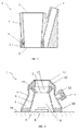
Figure 1 a.- Shows a side perspective view of an auxiliary element for the local deposition of paint, according to a preferred realization. -
Figure 1b .- Shows a bottom perspective view of an auxiliary element for the local deposition of paint, according to a preferred realization. -
Figure 2 .- Shows a longitudinal cross section of the realization offigure 1 . -
Figure 3 .- Shows a longitudinal cross section of a second realization. -
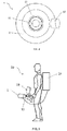
Figure 4 .- Shows a top view of the second realization of the invention. -
Figure 5 .- Shows a perspective view of the equipment for the local deposition of paint. - In a preferred realization of the invention, the auxiliary element for the local deposition of fluid, such as paint, comprises, as shown in
figures 1-4 , a hollow main body (2), a hollow conduit (3) and a cavity (4). - The hollow main body (2) is the element forming the external wall of the auxiliary element (1), which may be bell shaped, as can be seen in
figure 1 . - The hollow conduit (3) is located inside the main body (2) and is used to channel the pulverized paint, which may also be protective or isolating material, through its interior. This material enters through one end of the hollow conduit (3) from a paint dispenser, through a paint inlet opening (5), and flows towards a paint outlet opening (6) at the opposite end.
- The edge of the paint inlet opening (5) is in direct contact with the surface (18) of the part to be pulverized, and must have such dimensions as to allow the protuberance (9) to be pulverized to enter into the end of the hollow conduit (3), for the optimal deposition or dispersion of material over its surface. This optimal deposition must provide a minimal quantity of material to isolate the entire surface and grooves of the protuberance (9) from the exterior, and it must meet in-house quality standards, depending on the process.
- The cavity (4) is located between the wall of the main body (2) and the hollow conduit (3), and through its interior pass the suspended particles of pulverized paint, or protective or isolating material if applicable, which are harmful to human health .These residual particles, such as volatiles or particles in suspension, are the excess pulverized material that does not adhere to the surface of the protuberance (9) or the surface (18) of the part. For these particles to pass from the interior of the hollow conduit (3) to the cavity (4) of residual particles, the hollow conduit (3) comprises a plurality of holes as a connecting means (8).
- On the wall of the main body (2) there is an opening (7) that allows residual particles to exit the cavity (4), which will go to a volatiles sink.
- According to a second realization, shown in
figures 3 and4 , to the residual particles outlet opening (7) is coupled, either directly or by means of an auxiliary conduit, not shown in the figures, a fixed volatiles sink, such as an air purification filter (13), or an extractable volatiles sink, such as an aspirator (14). - In this second realization, the inlet conduit (12) comprises a notch, or recess (15) with the shape of the header connection of the paint dispenser (11), or another pulverizer device, as applicable. This connection can either be universal or specific to a certain header (11).
- In addition, the paint inlet opening (5) comprises an inlet conduit (12), configured to couple to the header of the paint dispenser (10), as can be seen in
figure 3 . The auxiliary element is fed with pulverized or non-pulverized material through this inlet conduit (12), and this inlet conduit (12) can have rigid or flexible shape depending on the operation to be carried out and the operating conditions. - Furthermore, the paint inlet opening (5) and the paint outlet opening (6) comprise an absorbent retention material (16, 16') around their edges. In the paint outlet opening (5), the position of the auxiliary element (1) is improved on the surface (18) of the part, as the support section increases. This also prevents material leaking from the hollow conduit (3) through the paint inlet opening (5) to adjacent zones. Lastly, the absorbent retention material (16) allows the material deposition zone to be marked out so that it meets the quality requirements and does not extend further than necessary, achieving savings of materials.
- Additionally, the absorbent retention material (16') around the edge of the paint inlet opening (5) also avoids the leakage of material through the part where material enters the auxiliary element (1) due to the fact that the pressure of the pulverized material is higher than atmospheric pressure.
- This absorbent retention material (16, 16') may be a sponge or other low density material that makes the material inlet (5) and outlet (6) openings leak tight to prevent leakages and waste of material.
- Lastly, the outermost layer of this second realization also comprises an elastomer material (17), which adapts to the shape of the header connection (11) of the paint dispenser, or any other element required to fasten the auxiliary element to the paint dispenser, and which also makes the material inlet opening (5) leak tight. This elastomer material (17) can be a rubber sheath.
- A final realization of the invention, according to
figure 5 , consists of an equipment (20) for the local deposition of paint, made up of: - an auxiliary element (1) for the local deposition of paint, and
- a paint dispenser (10), such as a paint gun or other type of material pulverizer, which provides or feeds protective or isolating material to be deposited on the protuberance (9).
- This final realization comprises an aspirator (14), which extracts excess pulverized material that does not adhere to the surface of the protuberance (9) or the surface (18) of the part, from the interior of the cavity (4) through the opening (7) of the residual particles outlet.
- In addition, to automate the process, the auxiliary element (1), along with the paint dispenser and a volatiles sink, are connected to an automated articulated arm using grips, not shown in the figures. This system comprises control software to deposit material on the protuberances (9) from computational references.
Claims (11)
- An auxiliary element (1) for the local deposition of fluid for a fluid dispenser header (10), characterized in that it comprises a hollow main body (2), comprising:- a hollow conduit (3) inside the main body (2), configured such that the fluid flows through its interior, comprising an opening for the inlet of fluid (5) coming from the fluid dispenser header at one end, and a fluid outlet opening (6) at the opposite end,- a cavity (4) located between the wall of the main body (2) and the hollow conduit (3), configured such that residual particles of the fluid flow through its interior,- at least one connecting means (8) of the interior of the hollow conduit (3) to the residual particles cavity (4) and- an opening (7) located on the main body (2), configured for the outlet of residual particles from the cavity (4).
- The auxiliary element (1) for the local deposition of paint for a fluid dispenser header (10), according to claim 1, wherein the fluid inlet opening (5) comprises an inlet conduit (12), configured to couple to the header of the fluid dispenser (10).
- The auxiliary element (1) for the local deposition of paint for a fluid dispenser header (10), according to claims 1-2, wherein the connecting means (8) is at least one passage that connects the interior of the hollow conduit (3) to the cavity (4).
- The auxiliary element (1) for the local deposition of paint for a fluid dispenser header (10), according to claims 1-2, wherein the connecting means (8) are a plurality of holes located in the hollow conduit (3).
- The auxiliary element (1) for the local deposition of fluid for a fluid dispenser header (10), according to any of the aforementioned claims, wherein the outlet opening (7) for residual particles comprises an air purification filter (13).
- The auxiliary element (1) for the local deposition of fluid for a fluid dispenser header (10), according to claims 2-5, wherein the inlet conduit (12) comprises a cut (15) with the shape of the connection of the header of the fluid dispenser (11).
- The auxiliary element (1) for the local deposition of fluid for a fluid dispenser header (10), according to any of the aforementioned claims, wherein the fluid inlet opening (5) and the fluid outlet opening (6) comprise an absorbent retention material (16, 16') around their edges.
- The auxiliary element (1) for the local deposition of fluid for a fluid dispenser header (10), according to any of the aforementioned claims, wherein the outermost layer of the fluid inlet opening (5) comprises an elastomer material (17).
- An equipment (20) for the local deposition of fluid, characterized in that it comprises:- an auxiliary element (1) for the local deposition of fluid, according to any of the claims 1-7, and- a fluid dispenser (10) configured to add fluid to the auxiliary element (1) joined to the fluid inlet opening (5) of the auxiliary element (1).
- The equipment (20) for the local deposition of fluid, according to claim 8, whereinit comprises an aspirator (14) coupled to the residual particles opening (7) of the auxiliary element (1).
- The equipment (20) for the local deposition of fluid, according to claims 8-9, wherein it comprises grips on the auxiliary element (1) and an automated articulated arm.
Priority Applications (2)
| Application Number | Priority Date | Filing Date | Title |
|---|---|---|---|
| EP16173896.8A EP3254765A1 (en) | 2016-06-10 | 2016-06-10 | Auxiliary local fluid deposition element |
| US15/619,059 US10525496B2 (en) | 2016-06-10 | 2017-06-09 | Auxiliary local fluid deposition element |
Applications Claiming Priority (1)
| Application Number | Priority Date | Filing Date | Title |
|---|---|---|---|
| EP16173896.8A EP3254765A1 (en) | 2016-06-10 | 2016-06-10 | Auxiliary local fluid deposition element |
Publications (1)
| Publication Number | Publication Date |
|---|---|
| EP3254765A1 true EP3254765A1 (en) | 2017-12-13 |
Family
ID=56132788
Family Applications (1)
| Application Number | Title | Priority Date | Filing Date |
|---|---|---|---|
| EP16173896.8A Withdrawn EP3254765A1 (en) | 2016-06-10 | 2016-06-10 | Auxiliary local fluid deposition element |
Country Status (2)
| Country | Link |
|---|---|
| US (1) | US10525496B2 (en) |
| EP (1) | EP3254765A1 (en) |
Cited By (1)
| Publication number | Priority date | Publication date | Assignee | Title |
|---|---|---|---|---|
| WO2021226539A1 (en) * | 2020-05-08 | 2021-11-11 | Prc-Desoto International, Inc. | Mask and air pressure control systems for use in coating deposition |
Families Citing this family (1)
| Publication number | Priority date | Publication date | Assignee | Title |
|---|---|---|---|---|
| JP6976154B2 (en) * | 2017-12-04 | 2021-12-08 | キヤノン株式会社 | Liquid discharge device, imprint device and method |
Citations (8)
| Publication number | Priority date | Publication date | Assignee | Title |
|---|---|---|---|---|
| GB1376695A (en) * | 1971-12-27 | 1974-12-11 | Ford Motor Co | Method of electrostatically applying a powder coating to an object |
| SU584898A1 (en) * | 1976-08-17 | 1977-12-25 | Предприятие П/Я А-1698 | Coating apparatus |
| US20060011747A1 (en) * | 2004-07-09 | 2006-01-19 | Horst Jahnke | Spraying device with droplet hold-back |
| DE202009005562U1 (en) * | 2009-04-16 | 2009-06-18 | G. Theodor Freese Gmbh & Co. Kg | Coating device with collecting funnel |
| US7837130B1 (en) * | 2007-01-16 | 2010-11-23 | Lowery Robert S | Overspray eradicator |
| WO2013191535A1 (en) * | 2012-05-24 | 2013-12-27 | Selmers Holding Bv | Apparatus for powder coating of a surface, more in particular for powder coating of the surface of a steel pipe |
| EP2859960A1 (en) * | 2013-10-09 | 2015-04-15 | Airbus Group SAS | Method for conditioning the surface of an object and assembly for implementing same |
| WO2016111624A1 (en) * | 2015-01-09 | 2016-07-14 | Stichting Quick Docking | Spraying element for applying a paint layer to a wall |
Family Cites Families (2)
| Publication number | Priority date | Publication date | Assignee | Title |
|---|---|---|---|---|
| US5319893A (en) * | 1992-01-28 | 1994-06-14 | Hockett Wayne B | Recovery system |
| WO2010122851A1 (en) * | 2009-04-21 | 2010-10-28 | シャープ株式会社 | Blasting apparatus and method for blasting |
-
2016
- 2016-06-10 EP EP16173896.8A patent/EP3254765A1/en not_active Withdrawn
-
2017
- 2017-06-09 US US15/619,059 patent/US10525496B2/en active Active
Patent Citations (8)
| Publication number | Priority date | Publication date | Assignee | Title |
|---|---|---|---|---|
| GB1376695A (en) * | 1971-12-27 | 1974-12-11 | Ford Motor Co | Method of electrostatically applying a powder coating to an object |
| SU584898A1 (en) * | 1976-08-17 | 1977-12-25 | Предприятие П/Я А-1698 | Coating apparatus |
| US20060011747A1 (en) * | 2004-07-09 | 2006-01-19 | Horst Jahnke | Spraying device with droplet hold-back |
| US7837130B1 (en) * | 2007-01-16 | 2010-11-23 | Lowery Robert S | Overspray eradicator |
| DE202009005562U1 (en) * | 2009-04-16 | 2009-06-18 | G. Theodor Freese Gmbh & Co. Kg | Coating device with collecting funnel |
| WO2013191535A1 (en) * | 2012-05-24 | 2013-12-27 | Selmers Holding Bv | Apparatus for powder coating of a surface, more in particular for powder coating of the surface of a steel pipe |
| EP2859960A1 (en) * | 2013-10-09 | 2015-04-15 | Airbus Group SAS | Method for conditioning the surface of an object and assembly for implementing same |
| WO2016111624A1 (en) * | 2015-01-09 | 2016-07-14 | Stichting Quick Docking | Spraying element for applying a paint layer to a wall |
Cited By (1)
| Publication number | Priority date | Publication date | Assignee | Title |
|---|---|---|---|---|
| WO2021226539A1 (en) * | 2020-05-08 | 2021-11-11 | Prc-Desoto International, Inc. | Mask and air pressure control systems for use in coating deposition |
Also Published As
| Publication number | Publication date |
|---|---|
| US10525496B2 (en) | 2020-01-07 |
| US20170354986A1 (en) | 2017-12-14 |
Similar Documents
| Publication | Publication Date | Title |
|---|---|---|
| DE102012210439B4 (en) | Apparatus for conveying coating powder from a powder container and method for cleaning a powder conveying apparatus | |
| EP3052367B1 (en) | Sand dispenser for a rail vehicle and method for providing sand for a rail vehicle | |
| US10525496B2 (en) | Auxiliary local fluid deposition element | |
| WO2015137808A1 (en) | Improved low pressure 2-k handheld spray gun | |
| US7631700B1 (en) | Firefighting vehicle | |
| EP1614482B1 (en) | Spraying device with droplets containment | |
| US8597076B2 (en) | Flexible enclosures for maintenance operations | |
| EP3556585B1 (en) | Roof structure and cabin | |
| CN106423692A (en) | Bell type anti-splash coating spraying device | |
| EP4253656B1 (en) | Control unit with fresh air device | |
| CN112153894B (en) | Pump assembly, spraying system, moving device and spraying method | |
| CN108787208A (en) | Water-repellent paint spray equipment | |
| CN220777189U (en) | Adjustable powder spraying device of plant protection unmanned aerial vehicle | |
| CN112153895B (en) | Spraying assembly, spraying system, moving device and spraying method | |
| CN209577090U (en) | The air painter for preventing spray painting from splashing | |
| EP2274110B1 (en) | Decontamination method and system for air intake plants, and cleaning head for said system | |
| RU2768841C1 (en) | Ultra-low-volume garden sprayer | |
| DE102016104761A1 (en) | Pig for applying liquid to the inner wall of a pipeline | |
| US9834394B2 (en) | Spray bar deflection tray | |
| CN118660763A (en) | Air curtain generating device and method for entering tank | |
| EP4204272B1 (en) | Pneumatic sand conveying device for a sanding system of a rail vehicle, sanding system, and method for operating a pneumatic sand conveying device | |
| CN213529192U (en) | Anti-splashing environment-friendly electrostatic spraying machine | |
| CN213384729U (en) | Plant protection unmanned aerial vehicle's hydrojet head | |
| DE267809C (en) | ||
| DE202012003467U1 (en) | cleaning hood |
Legal Events
| Date | Code | Title | Description |
|---|---|---|---|
| PUAI | Public reference made under article 153(3) epc to a published international application that has entered the european phase |
Free format text: ORIGINAL CODE: 0009012 |
|
| AK | Designated contracting states |
Kind code of ref document: A1 Designated state(s): AL AT BE BG CH CY CZ DE DK EE ES FI FR GB GR HR HU IE IS IT LI LT LU LV MC MK MT NL NO PL PT RO RS SE SI SK SM TR |
|
| AX | Request for extension of the european patent |
Extension state: BA ME |
|
| STAA | Information on the status of an ep patent application or granted ep patent |
Free format text: STATUS: THE APPLICATION IS DEEMED TO BE WITHDRAWN |
|
| 18D | Application deemed to be withdrawn |
Effective date: 20180614 |