EP3254714A1 - Vorrichtung und system zur abgabe eines fluids unter aseptischen bedingungen - Google Patents
Vorrichtung und system zur abgabe eines fluids unter aseptischen bedingungen Download PDFInfo
- Publication number
- EP3254714A1 EP3254714A1 EP16173551.9A EP16173551A EP3254714A1 EP 3254714 A1 EP3254714 A1 EP 3254714A1 EP 16173551 A EP16173551 A EP 16173551A EP 3254714 A1 EP3254714 A1 EP 3254714A1
- Authority
- EP
- European Patent Office
- Prior art keywords
- syringe
- needle
- fluid
- holder
- coupling element
- Prior art date
- Legal status (The legal status is an assumption and is not a legal conclusion. Google has not performed a legal analysis and makes no representation as to the accuracy of the status listed.)
- Granted
Links
Images


Classifications
-
- A—HUMAN NECESSITIES
- A61—MEDICAL OR VETERINARY SCIENCE; HYGIENE
- A61M—DEVICES FOR INTRODUCING MEDIA INTO, OR ONTO, THE BODY; DEVICES FOR TRANSDUCING BODY MEDIA OR FOR TAKING MEDIA FROM THE BODY; DEVICES FOR PRODUCING OR ENDING SLEEP OR STUPOR
- A61M5/00—Devices for bringing media into the body in a subcutaneous, intra-vascular or intramuscular way; Accessories therefor, e.g. filling or cleaning devices, arm-rests
- A61M5/14—Infusion devices, e.g. infusing by gravity; Blood infusion; Accessories therefor
- A61M5/162—Needle sets, i.e. connections by puncture between reservoir and tube ; Connections between reservoir and tube
-
- A—HUMAN NECESSITIES
- A61—MEDICAL OR VETERINARY SCIENCE; HYGIENE
- A61M—DEVICES FOR INTRODUCING MEDIA INTO, OR ONTO, THE BODY; DEVICES FOR TRANSDUCING BODY MEDIA OR FOR TAKING MEDIA FROM THE BODY; DEVICES FOR PRODUCING OR ENDING SLEEP OR STUPOR
- A61M5/00—Devices for bringing media into the body in a subcutaneous, intra-vascular or intramuscular way; Accessories therefor, e.g. filling or cleaning devices, arm-rests
- A61M5/14—Infusion devices, e.g. infusing by gravity; Blood infusion; Accessories therefor
- A61M5/142—Pressure infusion, e.g. using pumps
- A61M5/145—Pressure infusion, e.g. using pumps using pressurised reservoirs, e.g. pressurised by means of pistons
- A61M5/1452—Pressure infusion, e.g. using pumps using pressurised reservoirs, e.g. pressurised by means of pistons pressurised by means of pistons
- A61M5/1456—Pressure infusion, e.g. using pumps using pressurised reservoirs, e.g. pressurised by means of pistons pressurised by means of pistons with a replaceable reservoir comprising a piston rod to be moved into the reservoir, e.g. the piston rod is part of the removable reservoir
-
- A—HUMAN NECESSITIES
- A61—MEDICAL OR VETERINARY SCIENCE; HYGIENE
- A61M—DEVICES FOR INTRODUCING MEDIA INTO, OR ONTO, THE BODY; DEVICES FOR TRANSDUCING BODY MEDIA OR FOR TAKING MEDIA FROM THE BODY; DEVICES FOR PRODUCING OR ENDING SLEEP OR STUPOR
- A61M39/00—Tubes, tube connectors, tube couplings, valves, access sites or the like, specially adapted for medical use
- A61M39/10—Tube connectors; Tube couplings
- A61M39/16—Tube connectors; Tube couplings having provision for disinfection or sterilisation
- A61M39/165—Shrouds or protectors for aseptically enclosing the connector
-
- A—HUMAN NECESSITIES
- A61—MEDICAL OR VETERINARY SCIENCE; HYGIENE
- A61M—DEVICES FOR INTRODUCING MEDIA INTO, OR ONTO, THE BODY; DEVICES FOR TRANSDUCING BODY MEDIA OR FOR TAKING MEDIA FROM THE BODY; DEVICES FOR PRODUCING OR ENDING SLEEP OR STUPOR
- A61M5/00—Devices for bringing media into the body in a subcutaneous, intra-vascular or intramuscular way; Accessories therefor, e.g. filling or cleaning devices, arm-rests
- A61M5/14—Infusion devices, e.g. infusing by gravity; Blood infusion; Accessories therefor
- A61M5/142—Pressure infusion, e.g. using pumps
- A61M5/14244—Pressure infusion, e.g. using pumps adapted to be carried by the patient, e.g. portable on the body
-
- A—HUMAN NECESSITIES
- A61—MEDICAL OR VETERINARY SCIENCE; HYGIENE
- A61M—DEVICES FOR INTRODUCING MEDIA INTO, OR ONTO, THE BODY; DEVICES FOR TRANSDUCING BODY MEDIA OR FOR TAKING MEDIA FROM THE BODY; DEVICES FOR PRODUCING OR ENDING SLEEP OR STUPOR
- A61M5/00—Devices for bringing media into the body in a subcutaneous, intra-vascular or intramuscular way; Accessories therefor, e.g. filling or cleaning devices, arm-rests
- A61M5/178—Syringes
- A61M5/31—Details
- A61M5/315—Pistons; Piston-rods; Guiding, blocking or restricting the movement of the rod or piston; Appliances on the rod for facilitating dosing ; Dosing mechanisms
- A61M5/31511—Piston or piston-rod constructions, e.g. connection of piston with piston-rod
-
- A—HUMAN NECESSITIES
- A61—MEDICAL OR VETERINARY SCIENCE; HYGIENE
- A61M—DEVICES FOR INTRODUCING MEDIA INTO, OR ONTO, THE BODY; DEVICES FOR TRANSDUCING BODY MEDIA OR FOR TAKING MEDIA FROM THE BODY; DEVICES FOR PRODUCING OR ENDING SLEEP OR STUPOR
- A61M5/00—Devices for bringing media into the body in a subcutaneous, intra-vascular or intramuscular way; Accessories therefor, e.g. filling or cleaning devices, arm-rests
- A61M5/14—Infusion devices, e.g. infusing by gravity; Blood infusion; Accessories therefor
- A61M5/142—Pressure infusion, e.g. using pumps
- A61M5/14244—Pressure infusion, e.g. using pumps adapted to be carried by the patient, e.g. portable on the body
- A61M2005/14268—Pressure infusion, e.g. using pumps adapted to be carried by the patient, e.g. portable on the body with a reusable and a disposable component
-
- A—HUMAN NECESSITIES
- A61—MEDICAL OR VETERINARY SCIENCE; HYGIENE
- A61M—DEVICES FOR INTRODUCING MEDIA INTO, OR ONTO, THE BODY; DEVICES FOR TRANSDUCING BODY MEDIA OR FOR TAKING MEDIA FROM THE BODY; DEVICES FOR PRODUCING OR ENDING SLEEP OR STUPOR
- A61M39/00—Tubes, tube connectors, tube couplings, valves, access sites or the like, specially adapted for medical use
- A61M2039/0036—Tubes, tube connectors, tube couplings, valves, access sites or the like, specially adapted for medical use characterised by a septum having particular features, e.g. having venting channels or being made from antimicrobial or self-lubricating elastomer
-
- A—HUMAN NECESSITIES
- A61—MEDICAL OR VETERINARY SCIENCE; HYGIENE
- A61M—DEVICES FOR INTRODUCING MEDIA INTO, OR ONTO, THE BODY; DEVICES FOR TRANSDUCING BODY MEDIA OR FOR TAKING MEDIA FROM THE BODY; DEVICES FOR PRODUCING OR ENDING SLEEP OR STUPOR
- A61M2205/00—General characteristics of the apparatus
- A61M2205/12—General characteristics of the apparatus with interchangeable cassettes forming partially or totally the fluid circuit
Definitions
- the present invention relates to an apparatus and a system for dispensing a fluid under aseptic conditions and the use of such a device or system for dispensing a fluid, in particular under aseptic conditions, according to the preambles of the independent claims.
- pens for parenteral injection of liquid formulations of active pharmaceutical ingredients, in addition to hypodermic syringes and medication sticks (so-called pens), it has also proven useful in the recent past.
- Such pumps are particularly advantageous when a preparation according to a specially predetermined scheme, for example, over a long period of time, regardless of the presence of medical personnel on a patient must be delivered.
- the pumps can be attached to the patient's body depending on the application and typically include a container for the liquid formulation as well as a delivery device that conveys it to a connector or to an injection system.
- the injection system may comprise an indwelling cannula which remains in the body of the patient throughout the period of administration.
- the drug Neulasta® contains the active substance pegfilgrastim, which belongs to the group of cytokines and is very similar to an endogenous protein, the granulocyte-colony-stimulating factor. Neulasta® is used to reduce the duration of neutropenia (low white blood cell counts) and reduce the incidence of neutropensic fiber (low white blood cell count associated with fever). These conditions may be due to the use of a cytotoxic Chemotherapy (drugs that destroy fast growing cells). If the number of white blood cells drops to a low level, the body may no longer have enough of these cells to fight against pathogens, leading to an increased risk of infection.
- pegfilgrastim belongs to the group of cytokines and is very similar to an endogenous protein, the granulocyte-colony-stimulating factor.
- Neulasta® is used to reduce the duration of neutropenia (low white blood cell counts) and reduce the incidence of neutropensic fiber (low white blood cell count associated with fever). These conditions may be due to
- Neulasta® is available as a pre-filled syringe containing a single dose of 6 mg in 0.6 ml solution for injection.
- the solution is injected subcutaneously (i.e., under the skin).
- the dose must be given according to a strictly prescribed schedule, usually 24 hours after the last dose of the chemotherapeutic agent at the end of each treatment cycle. If the administration is not performed as prescribed, the preparation may be ineffective.
- the drug delivered in a disposable syringe is offered as a kit with a drug pump (brand name: Onpro TM). Said drug pump must be filled by a healthcare professional via a fill port with the solution from the syringe. Once attached to the body of the patient, the medication is dispensed over a period of 45 minutes 27 hours after activation of the pump.
- the use of said drug pump has the advantage that a re-visit to a doctor, only for the administration of Neulasta®, is no longer necessary. Also, because the patient does not need to inject himself with the preparation, he or she will forget about the administration or make mistakes (especially with regard to his state of health).
- the said drug pump Onpro TM has relatively many items, which is why they consuming and expensive in production.
- the solution with the pre-filled syringe must be filled into the drug pump via a comparatively small septum. This can only be done by medical personnel.
- the device should be suitable for handling by a patient.
- the device for delivering a fluid under aseptic conditions comprises a delivery device for delivering the fluid to a delivery port. Furthermore, the device comprises a coupling element for coupling a syringe. The fluid can be conveyed from the syringe via the coupling element and the conveying device exclusively to the discharge opening under the action of the conveying device.
- the delivery device generates a negative pressure on the side of the syringe, whereby the content of the syringe is sucked out of it and the piston of the syringe moves by the suction force in the direction of the proximal end of the syringe.
- the conveying device for this purpose must provide sufficient suction.
- this embodiment of the device can be dispensed with a separate container for receiving the fluid.
- This function is taken over by the syringe, which in many cases is prefilled by the manufacturer with the fluid. This can reduce the total number of parts of the system, resulting in higher reliability and lower costs.
- pharmaceuticals are subject to strict regulations and the introduction of new packaging is subject to registration, it is advantageous that a classical syringe can be used both for injection and in conjunction with the device. This can be costly and expensive additional approval procedures are avoided. Since the fluid does not yet have to be transferred to another container, but is transferred directly from the syringe via the delivery device to the patient, the risk of contamination of the fluid and thus a risk to the patient can also be reduced.
- the coupling element may comprise a septum that can be penetrated by a syringe needle or cannula. This is particularly advantageous when the syringe comprises a fixed syringe needle or cannula, as is common in pre-filled syringes. However, this embodiment is also advantageous in syringes with replaceable needle, since the connection between the syringe and the conveyor can be made in a very hygienic way.
- the coupling element may be formed as a needle receptacle, in which the septum is inserted, in particular in a circumferential groove.
- the needle receptacle may be formed as, in particular curved, line section.
- the formation of the coupling element as a needle holder has the advantage that the needle controlled for the piercing of the septum and then safely held.
- the needle holder may be formed integrally with the housing of the device. This makes it possible to constructively hold such a device with needle receptacle and manufacture it in an efficient, cost-effective manner.
- the needle receptacle can be in fluid communication with a conduit element, in particular a steel cannula, wherein the conduit element is preferably embedded in a wall of the needle receptacle, in particular extrusion-coated or via a sealing element, in particular a further septum, which is preferably inserted into a circumferential groove of the needle receptacle, be connected to the needle holder.
- a sealing element in particular a further septum, which is preferably inserted into a circumferential groove of the needle receptacle, be connected to the needle holder.
- the needle receptacle Via the line element, the needle receptacle can be fluidly connected to other parts of the device, in particular to the conveying device.
- the embedding of the conduit element in a wall of the needle holder or the use of a sealing element are structurally advantageous variants to connect the conduit member with the needle holder.
- the device may comprise a holder, in which the syringe can be inserted, wherein the syringe, when it is inserted into the holder, can be coupled to the device via the coupling element.
- a holder has the advantage that the syringe, when connected to the device, is securely held in its intended position.
- the holder can be simplified by the holder, the coupling of the syringe to the coupling element, in particular guided.
- such a device can also be used safely by non-medically trained personnel, in particular by the patient himself.
- the holder can be designed as a slot which can be inserted into an insertion region of the device. Characterized in that the syringe is first inserted into a slot before it is inserted into the device and thus a coupling of the device takes place on the coupling element, the use of the device can be further simplified.
- the drawer can have a pull-off element, with which a protective cap of a syringe inserted in the drawer can be pulled off. This can further simplify the use of the device, especially for a patient.
- Another aspect of the present invention relates to a system for delivering a fluid under aseptic conditions comprising a device as described above and a syringe coupleable to the coupling element.
- the device can be used to deliver a syringe specifically adapted to it.
- This relates in particular to the dimensions of the syringe, for example the length and diameter of a fixed syringe needle and its general construction. So it is possible, for example, that the syringe is designed without a piston rod.
- the syringe may have a particular firmly attached to the syringe body hollow needle or cannula. This is common nowadays in pre-filled syringes. On the one hand, it can be used to avoid contamination of the fluid when attaching a separate syringe needle. On the other hand, this leads to a simplification of Use, as a separate step for attaching a syringe needle or cannula deleted.
- the device may include a syringe holder configured to shield the syringe needle or cannula of a syringe inserted therein. This can essentially be prevented that injures a user of the device after removing the protective cap on the syringe needle.
- the present invention further relates to the use of a device or system as described above for dispensing a fluid, particularly under aseptic conditions.
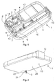
- FIG. 1 shows a device 1 according to the invention, wherein for better clarity of the upper part of a housing 10 is omitted.
- individual parts of the device 1 such as a conveyor drive or control electronics are not shown.
- a holder for the syringe 5 is designed as a slot 13, which is inserted here into the device 1.
- the syringe 5 has a piston 17 on which, in contrast to common syringes no piston rod is mounted.
- the syringe 5 has a permanently attached syringe needle 6. It can be seen that the syringe needle 6 projects into a coupling element 4, which in the present example is designed as a needle receptacle 8.
- the area of the needle receptacle 8 facing the syringe 5 is funnel-shaped in this case in order to guide the syringe needle 6 in the direction of a septum 7.
- the septum 7 is embedded in a circumferential groove 9 of a wall 12 of the needle holder 8.
- the needle holder 8 is formed as a curved line section, which is formed integrally with the housing 10 of the device 1.
- the needle holder 8 is connected to the conveying device 2 via a line element 11, which is designed here as a steel cannula.
- the device 1 has an injection device 18, which both on one of a not shown driven drive drum 19 driven or controlled.
- FIG. 3 the device 1 described above and the insert 13 with the syringe 5 are shown separately. It can be seen that the syringe needle 6 is largely shielded by the insert 5, whereby it can be prevented that a user injured.
- the insert 13 is inserted into an insertion region 14 of the device 1, whereby the syringe needle 6 is inserted into the needle holder 8 and the septum 7 is pierced.
- FIGS. 4 to 7 From the FIGS. 4 to 7 is the insertion of the syringe 5 in the slot 13 and the removal of a protective cap 16 of the syringe 5 shown.
- FIG. 4 are the drawer 13 with a puller 15 on the one hand and the syringe 5 with the cap 16 on the other hand individually shown.
- FIG. 5 the syringe 5 is inserted into the slot 13. It can be seen that engaging elements 23 of the peeling element 15 engage in a groove 24 of the protective cap 16.
- FIG. 6 is the protective cap 16 with the puller 15 already deducted from the syringe 5.
- FIG. 7 shows the puller 13 with the inserted syringe 5 ready for insertion into the device 1. It can be seen that the syringe needle 6 of the syringe 5 is substantially shielded by the insert 13, so that it can be prevented that a user injured on the syringe needle 6.
Landscapes
- Health & Medical Sciences (AREA)
- Heart & Thoracic Surgery (AREA)
- Hematology (AREA)
- Anesthesiology (AREA)
- Biomedical Technology (AREA)
- Engineering & Computer Science (AREA)
- Life Sciences & Earth Sciences (AREA)
- Animal Behavior & Ethology (AREA)
- General Health & Medical Sciences (AREA)
- Public Health (AREA)
- Veterinary Medicine (AREA)
- Vascular Medicine (AREA)
- Epidemiology (AREA)
- Pulmonology (AREA)
- Infusion, Injection, And Reservoir Apparatuses (AREA)
Abstract
Description
- Die vorliegende Erfindung betrifft eine Vorrichtung und ein System zur Abgabe eines Fluids unter aseptischen Bedingungen sowie die Verwendung einer derartigen Vorrichtung oder eines derartigen Systems zur Abgabe eines Fluids, insbesondere unter aseptischen Bedingungen, gemäss den Oberbegriffen der unabhängigen Ansprüche.
- Zur parenteralen Injektion flüssiger Formulierungen pharmazeutischer Wirkstoffe haben sich neben Injektionsspritzen und Arzneimittelstiften (sog. Pens) auch Arzneimittelpumpen in der jüngeren Vergangenheit bewährt. Derartige Pumpen sind insbesondere vorteilhaft, wenn ein Präparat nach einem speziell vorgegebenen Schema, beispielsweise über einen längeren Zeitraum, unabhängig von der Anwesenheit von medizinischem Personal an einem Patienten abgegeben werden muss. Die Pumpen können je nach Anwendung am Körper des Patienten angebracht werden und umfassen typischerweise einen Behälter für die flüssige Formulierung sowie eine Fördervorrichtung, die diese zu einem Anschluss oder zu einem Injektionssystem fördert. Das Injektionssystem kann eine Verweilkanüle umfassen, die während des gesamten Verabreichungszeitraumes im Körper des Patienten verbleibt.
- Das Arzneimittel Neulasta® enthält den Wirkstoff Pegfilgrastim, der zu der Gruppe der Zytokine gehört und einem körpereigenem Protein, dem Granulozyten-Kolonien-stimulierenden-Faktor, sehr ähnlich ist. Neulasta® wird zur Verkürzung der Dauer von Neutropenien (niedrige Anzahl der weissen Blutkörperchen) und zur Verminderung des Vorkommens neutropensischen Fibers (niedrige Anzahl der weissen Blutkörperchen in Verbindung mit Fieber) eingesetzt. Diese Zustände können durch den Einsatz einer zytotoxischen Chemotherapie (Arzneimittel, die schnellwachsende Zellen zerstören) hervorgerufen werden. Wenn die Anzahl der weissen Blutkörperchen auf einen niedrigen Spiegel abfällt, stehen dem Körper möglicherweise nicht mehr genügend dieser Zellen zur Bekämpfung von Krankheitserregern zur Verfügung, was zu einem erhöhten Infektionsrisiko führt.
- Neulasta® ist als Fertigspritze erhältlich, die eine einzelne Dosis von 6 mg in 0.6 ml Injektionslösung enthält. Die Lösung wird subkutan (d.h. unter die Haut) gespritzt. Die Gabe muss dabei nach einem streng vorgegebenen Zeitschema erfolgen, üblicherweise 24h nach der letzten Dosis des Chemotherapeutikums am Ende eines jeden Behandlungszyklus. Erfolgt die Verabreichung nicht gemäss den Vorgaben, kann das Präparat unter Umständen wirkungslos sein.
- Um die Verabreichung von Neulasta® für den Patienten zu vereinfachen, wird das in einer Einwegspritze gelieferte Medikament als Set mit einer Arzneimittelpumpe (Markenname: Onpro™) angeboten. Die besagte Arzneimittelpumpe muss von medizinischem Fachpersonal über eine Einfüllöffnung mit der Lösung aus der Spritze befüllt werden. Einmal am Körper des Patienten angebracht, erfolgt 27 Stunden nach Aktivierung der Pumpe die Abgabe des Medikamentes über einen Zeitraum von 45 Minuten. Die Verwendung der besagten Arzneimittelpumpe hat den Vorteil, dass ein erneuter Arztbesuch, einzig zur Verabreichung von Neulasta®, nicht mehr erforderlich ist. Da sich der Patient das Präparat auch nicht selbst injizieren muss, wird verhindert, dass dieser die Verabreichung vergisst oder ihm dabei Fehler unterlaufen (gerade im Hinblick auf seinen Gesundheitszustand).
- Die besagte Arzneimittelpumpe Onpro™ weist allerdings verhältnismässig viele Einzelteile auf, weshalb sie aufwendig und kostenintensiv in der Fertigung ist. Zudem muss die Lösung mit der vorgefüllten Spritze über ein vergleichsweise kleines Septum in die Arzneimittelpumpe eingefüllt werden. Dies kann nur von medizinischem Personal bewerkstelligt werden. Darüber hinaus besteht die Gefahr, dass es beim Umfüllen der Lösung zu einer Kontamination derselben kommt.
- Es ist daher eine Aufgabe der vorliegenden Erfindung, die Nachteile im Stand der Technik zu überwinden. Insbesondere ist es eine Aufgabe der Erfindung, eine vielfältig anwendbare und konstruktiv einfache Vorrichtung zur Abgabe eines Fluids unter aseptischen Bedingungen zu schaffen, die preisgünstiger herzustellen ist. Zudem soll die Vorrichtung für die Handhabung durch einen Patienten geeignet sein.
- Diese Aufgaben werden durch eine Vorrichtung sowie ein System gelöst, welche die Merkmale in den unabhängigen Ansprüchen aufweisen.
- Die Vorrichtung zur Abgabe eines Fluids unter aseptischen Bedingungen umfasst eine Fördervorrichtung zur Förderung des Fluids zu einer Abgabeöffnung. Ferner umfasst die Vorrichtung ein Kopplungselement zum Ankoppeln einer Spritze. Das Fluid ist von der Spritze über das Kopplungselement und die Fördervorrichtung ausschliesslich unter Einwirkung der Fördervorrichtung zur Abgabeöffnung förderbar.
- Insbesondere erzeugt die Fördervorrichtung dabei auf der Seite der Spritze einen Unterdruck, wodurch der Inhalt der Spritze aus dieser ausgesaugt wird und sich der Kolben der Spritze durch die Saugkraft in Richtung des proximalen Endes der Spritze bewegt. Es versteht sich von selbst, dass die Fördervorrichtung hierzu eine ausreichende Saugkraft bereitstellen muss.
- Durch diese Ausgestaltung der Vorrichtung kann auf einen separaten Behälter zur Aufnahme des Fluids verzichtet werden. Diese Funktion wird von der Spritze übernommen, die in vielen Fällen von Seiten des Herstellers mit dem Fluid vorgefüllt ist. Dadurch kann die Gesamtzahl der Teile des Systems reduziert werden, was in einer höheren Zuverlässigkeit und in geringeren Kosten resultiert. Da Pharmazeutika strengen Regulatorien unterliegen und die Einführung einer neuen Verpackung registrierungspflichtig ist, ist es ferner vorteilhaft, dass eine klassische Spritze sowohl zur Injektion als auch in Verbindung mit der Vorrichtung verwendet werden kann. Damit können aufwendige und kostenintensive weitere Zulassungsverfahren vermieden werden. Da das Fluid nicht noch in einen weiteren Behälter transferiert werden muss, sondern direkt von der Spritze über die Fördervorrichtung zum Patienten transferiert wird, kann zudem das Risiko einer Kontamination des Fluids und damit einer Gefährdung des Patienten verringert werden.
- Das Kopplungselement kann ein von einer Spritzennadel oder Kanüle penetrierbares Septum umfassen. Dies ist insbesondere vorteilhaft, wenn die Spritze eine fest angebrachte Spritzennadel oder Kanüle umfasst, wie es bei Fertigspritzen im Allgemeinen üblich ist. Allerdings ist diese Ausführung auch bei Spritzen mit auswechselbarer Nadel vorteilhaft, da die Verbindung zwischen der Spritze und der Fördervorrichtung so auf eine überaus hygienische Weise hergestellt werden kann.
- Das Kopplungselement kann als Nadelaufnahme ausgebildet sein, in welche das Septum eingesetzt ist, insbesondere in eine umlaufende Nut. Die Nadelaufnahme kann als, insbesondere gekrümmter, Leitungsabschnitt ausgebildet sein. Die Ausbildung des Kopplungselementes als Nadelaufnahme hat den Vorteil, dass die Nadel für das Durchstechen des Septums kontrolliert geführt und danach sicher gehalten werden kann. Die Nadelaufnahme kann einstückig mit dem Gehäuse der Vorrichtung ausgebildet sein. Dies ermöglicht es, eine derartige Vorrichtung mit Nadelaufnahme konstruktiv einfach zu halten und auf effiziente, kostengünstige Weise zu fertigen.
- Die Nadelaufnahme kann mit einem Leitungselement, insbesondere einer Stahlkanüle, in Fluidkommunikation stehen, wobei das Leitungselement bevorzugt in eine Wand der Nadelaufnahme eingebettet, insbesondere umspritzt ist oder über ein Dichtungselement, insbesondere ein weiteres Septum, welches vorzugsweise in eine umlaufende Nut der Nadelaufnahme eingesetzt ist, mit der Nadelaufnahme verbunden sein. Über das Leitungselement kann die Nadelaufnahme mit weiteren Teilen der Vorrichtung, insbesondere mit der Fördervorrichtung fluidmässig verbunden sein. Das Einbetten des Leitungselementes in eine Wand der Nadelaufnahme oder die Verwendung eines Dichtungselementes stellen dabei konstruktiv vorteilhafte Varianten dar, um das Leitungselement mit der Nadelaufnahme zu verbinden.
- Die Vorrichtung kann eine Halterung umfassen, in welche die Spritze einlegbar ist, wobei die Spritze, wenn sie in die Halterung eingelegt ist, über das Kopplungselement an die Vorrichtung ankoppelbar ist. Eine Halterung hat den Vorteil, dass die Spritze, wenn sie mit der Vorrichtung verbunden ist, sicher an ihrer vorgesehenen Position gehalten wird. Darüber hinaus kann durch die Halterung das Ankoppeln der Spritze an das Kopplungselement vereinfacht, insbesondere geführt werden. Dadurch kann eine derartige Vorrichtung auch von nicht medizinisch geschultem Personal, insbesondere vom Patienten selbst, sicher verwendet werden.
- Die Halterung kann als Einschub ausgebildet sein, der in einen Einschubbereich der Vorrichtung einschiebbar ist. Dadurch, dass die Spritze erst in einen Einschub eingelegt wird, bevor dieser in die Vorrichtung eingeschoben wird und damit ein Ankoppeln der Vorrichtung an das Kopplungselement erfolgt, kann die Verwendung der Vorrichtung weiter vereinfacht werden. Der Einschub kann ein Abziehelement aufweisen, mit dem eine Schutzkappe einer in den Einschub eingelegten Spritze abziehbar ist. Dies kann die Verwendung der Vorrichtung, insbesondere für einen Patienten, weiter vereinfachen.
- Ein weiterer Aspekt der vorliegenden Erfindung betrifft ein System zur Abgabe eines Fluids unter aseptischen Bedingungen umfassend eine Vorrichtung wie vorgängig beschrieben und eine mit dem Kopplungselement koppelbare Spritze. Durch das Bereitstellen von Vorrichtung und Spritze als System kann mit der Vorrichtung eine Spritze geliefert werden, die speziell auf diese abgestimmt ist. Dies bezieht sich insbesondere auf die Dimensionen der Spritze, beispielsweise auf die Länge und den Durchmesser einer fest angebrachten Spritzennadel und auf deren allgemeine Konstruktionsweise. So ist es beispielsweise möglich, dass die Spritze ohne Kolbenstange ausgeführt ist. Dies verringert insbesondere die Gesamtlänge der Spritze bei zurückgezogenem Kolben, was vor allem bei vorgefüllten Fertigspritzen vorteilhaft ist, um die Grösse der Vorrichtung und der Verpackung der Spritze zu reduzieren.
- Die Spritze kann eine insbesondere fest am Spritzenkörper angebrachte Hohlnadel oder Kanüle aufweisen. Dies ist heutzutage bei Fertigspritzen gängig. Einerseits kann damit eine Kontamination des Fluids beim Anbringen einer separaten Spritzennadel vermieden werden. Andererseits führt dies zu einer Vereinfachung der Verwendung, da ein separater Schritt für das Anbringen einer Spritzennadel oder Kanüle entfällt.
- Bei einem derartigen System kann die Vorrichtung einen Spritzenhalter umfassen, welcher derart ausgestaltet ist, dass die Spritzennadel oder Kanüle einer darin eingelegten Spritze abgeschirmt ist. Damit kann im Wesentlichen verhindert werden, dass sich ein Anwender der Vorrichtung nach Entfernen der Schutzkappe an der Spritzennadel verletzt.
- Die vorliegende Erfindung betrifft darüber hinaus die Verwendung einer Vorrichtung oder eines Systems wie oben beschrieben zur Abgabe eines Fluids, insbesondere unter aseptischen Bedingungen.
- Weitere Vorteile und Einzelmerkmale der Erfindung ergeben sich aus der nachfolgenden Beschreibung eines Ausführungsbeispiels und aus den Zeichnungen.
- Es zeigen schematisch:
- Figur 1:
- Perspektivische Darstellung der Oberseite einer erfindungsgemässen Vorrichtung;
- Figur 2:
- Perspektivische Darstellung der Unterseite der Vorrichtung gemäss
Figur 1 ; - Figur 3:
- Perspektivische Darstellung der Vorrichtung gemäss den
Figuren 1 und 2 , jedoch mit separat dargestellter Halterung, welche als Einschub ausgebildet ist, in welchen eine Spritze eingelegt ist; - Figuren 4 bis 7:
- Perspektivische Darstellung einer Folge von Schritten, welche das Einlegen einer Spritze in den Einschub einer Vorrichtung gemäss den
Figuren 1 bis 3 sowie das Abziehen der Schutzkappe der Spritze darstellt. -
Figur 1 zeigt eine erfindungsgemässe Vorrichtung 1, wobei zur besseren Übersichtlichkeit der Oberteil eines Gehäuses 10 weggelassen ist. Zudem sind einzelne Teile der Vorrichtung 1 wie beispielsweise ein Förderantrieb oder eine Steuerungselektronik nicht dargestellt. Bei der dargestellten Vorrichtung ist eine Halterung für die Spritze 5 als Einschub 13 ausgestaltet, welcher hier in die Vorrichtung 1 eingeschoben ist. Die Spritze 5 weist einen Kolben 17 auf, an dem im Gegensatz zu gängigen Spritzen keine Kolbenstange angebracht ist. Zudem weist die Spritze 5 eine fest angebrachte Spritzennadel 6 auf. Es ist zu erkennen, dass die Spritzennadel 6 in ein Kopplungselement 4 hineinragt, welches im vorliegenden Beispiel als Nadelaufnahme 8 ausgebildet ist. Der der Spritze 5 zugewandte Bereich der Nadelaufnahme 8 ist dabei trichterförmig ausgeführt um die Spritzennadel 6 in Richtung eines Septums 7 zu leiten. Das Septum 7 ist in einer umlaufenden Nut 9 einer Wand 12 der Nadelaufnahme 8 eingebettet. Die Nadelaufnahme 8 ist als gekrümmter Leitungsabschnitt ausgebildet, welcher einstückig mit dem Gehäuse 10 der Vorrichtung 1 ausgebildet ist. Die Nadelaufnahme 8 ist über ein Leitungselement 11, welches hier als Stahlkanüle ausgebildet ist, mit der Fördervorrichtung 2 verbunden. Der fluidmässige Anschluss des Leitungselementes 11 an die Nadelaufnahme 8 erfolgt über ein Septum 7, welches ebenfalls in eine umlaufende Nut 9' innerhalb der Wand 12 der Nadelaufnahme 8 eingebettet ist. Neben der Fördervorrichtung 2 verfügt die Vorrichtung 1 über eine Injektionsvorrichtung 18, welche beide über eine von einem nicht dargestellten Förderantrieb angetriebene Kurventrommel 19 angetrieben bzw. gesteuert werden. - Aus
Figur 2 ist eine Unterseite der Vorrichtung 1 ersichtlich. Es ist zu erkennen, dass das Gehäuse 10 dort eine Kontaktfläche 20 aufweist, über die die Vorrichtung 1, insbesondere über einen Klebefilm, an den Körper eines Patienten anbringbar ist. Im gezeigten Ausführungsbeispiel der Vorrichtung 1 ist eine Abgabeöffnung 3 als eine Kombination von Einstechkanüle und Verweilkanüle 21 ausgeführt, welche über einen Setzmechanismus der Injektionsvorrichtung 18 durch die Öffnung 22 im Gehäuse 10 gesetzt werden. - In
Figur 3 sind die vorgängig beschriebene Vorrichtung 1 und der Einschub 13 mit der Spritze 5 separat dargestellt. Es ist zu erkennen, dass die Spritzennadel 6 durch den Einschub 5 weitestgehend abgeschirmt ist, wodurch verhindert werden kann, dass sich ein Benutzer damit verletzt. Der Einschub 13 wird in einen Einschubbereich 14 der Vorrichtung 1 eingeschoben, wodurch die Spritzennadel 6 in die Nadelaufnahme 8 eingeführt und das Septum 7 durchstochen wird. - Aus den
Figuren 4 bis 7 ist das Einlegen der Spritze 5 in den Einschub 13 und das Abziehen einer Schutzkappe 16 von der Spritze 5 dargestellt. InFigur 4 sind der Einschub 13 mit einem Abziehelement 15 einerseits und die Spritze 5 mit der Schutzkappe 16 andererseits einzeln dargestellt. InFigur 5 ist die Spritze 5 in den Einschub 13 eingelegt. Es ist zu erkennen, dass Eingriffelemente 23 des Abziehelementes 15 in eine Nut 24 der Schutzkappe 16 eingreifen. InFigur 6 ist die Schutzkappe 16 mit dem Abziehelement 15 bereits von der Spritze 5 abgezogen.Figur 7 zeigt das Abziehelement 13 mit der eingelegten Spritze 5 bereit zum Einschieben in die Vorrichtung 1. Es ist zu erkennen, dass die Spritzennadel 6 der Spritze 5 durch den Einschub 13 im Wesentlichen abgeschirmt wird, so dass verhindert werden kann, dass sich ein Benutzer an der Spritzennadel 6 verletzt.
Claims (14)
- Vorrichtung (1) zur Abgabe eines Fluids unter aseptischen Bedingungen, umfassend eine Fördervorrichtung (2) zur Förderung des Fluids zu einer Abgabeöffnung (3), dadurch gekennzeichnet, dass die Vorrichtung (1) ein Kopplungselement (4) zum Ankoppeln einer Spritze (5) umfasst, wobei das Fluid von der Spritze (5) über das Kopplungselement (4) und die Fördervorrichtung (2) ausschliesslich unter Einwirkung der Fördervorrichtung (2) zur Abgabeöffnung (3) förderbar ist.
- Vorrichtung (1) nach Anspruch 1, wobei das Kopplungselement (4) ein von einer Spritzennadel oder Kanüle (6) penetrierbares Septum (7) umfasst.
- Vorrichtung (1) nach Anspruch 2, wobei das Kopplungselement (4) als Nadelaufnahme (8) ausgebildet ist, in welche das Septum (7) eingesetzt ist, insbesondere in eine umlaufende Nut (9).
- Vorrichtung (1) nach Anspruch 3, wobei die Nadelaufnahme (8) als, insbesondere gekrümmter, Leitungsabschnitt ausgebildet ist.
- Vorrichtung (1) nach einem der Ansprüche 3 oder 4, wobei die Nadelaufnahme (8) einstückig mit einem Gehäuse (10) der Vorrichtung (1) ausgebildet ist.
- Vorrichtung (1) nach einem der Ansprüche 3 bis 5, wobei die Nadelaufnahme (8) mit einem Leitungselement (11), insbesondere einer Stahlkanüle, in Fluidkommunikation steht, wobei das Leitungselement (11) bevorzugt in eine Wand (12) der Nadelaufnahme (8) eingebettet, insbesondre umspritzt, ist oder über ein Dichtungselement (7'), insbesondere ein weiteres Septum, welches vorzugsweise in eine umlaufende Nut (9') der Nadelaufnahme (8) eingesetzt ist, mit der Nadelaufnahme (8) verbunden ist.
- Vorrichtung (1) nach einem der Ansprüche 1 bis 6, umfassend eine Halterung, in welche die Spritze (5) einlegbar ist, wobei die Spritze (5), wenn sie in die Halterung (13) eingelegt ist, über das Kopplungselement (4) an die Vorrichtung (1) ankoppelbar ist.
- Vorrichtung (1) nach Anspruch 7, wobei die Halterung als Einschub (13) ausgebildet ist, der in einen Einschubbereich (14) der Vorrichtung (1) einschiebbar ist.
- Vorrichtung (1) nach Anspruch 8, wobei der Einschub (13) ein Abziehelement (15) aufweist, mit dem eine Schutzkappe (16) einer in den Einschub (13) eingelegten Spritze (5) abziehbar ist.
- System zur Abgabe eines Fluids unter aseptischen Bedingungen umfassend eine Vorrichtung (1) nach einem der Ansprüche 1 bis 9 und eine mit dem Kopplungselement (4) koppelbare Spritze (5).
- System nach Anspruch 10, wobei die Spritze (5) ohne Kolbenstange ausgeführt ist.
- System nach einem der Ansprüche 10 oder 11, wobei die Spritze (6) eine insbesondere fest am Spritzenkörper angebrachte Hohlnadel oder Kanüle (6) aufweist.
- System nach Anspruch 12, wobei die Vorrichtung (1) einen Spritzenhalter (13) umfasst, welcher derart ausgestaltet ist, dass die Spritzennadel oder Kanüle (6) einer darin eingelegten Spritze (5) abgeschirmt ist.
- Verwendung einer Vorrichtung (1) nach einem der Ansprüche 1 bis 9 oder eines Systems nach einem der Ansprüche 11 bis 13 zur Abgabe eines Fluids, insbesondere unter aseptischen Bedingungen.
Priority Applications (3)
| Application Number | Priority Date | Filing Date | Title |
|---|---|---|---|
| EP16173551.9A EP3254714B1 (de) | 2016-06-08 | 2016-06-08 | Vorrichtung und system zur abgabe eines fluids unter aseptischen bedingungen |
| US16/305,208 US11191895B2 (en) | 2016-06-08 | 2017-05-17 | Device and system for dispensing a fluid under aseptic conditions |
| PCT/EP2017/061883 WO2017211558A1 (de) | 2016-06-08 | 2017-05-17 | Vorrichtung und system zur abgabe eines fluids unter aseptischen bedingungen |
Applications Claiming Priority (1)
| Application Number | Priority Date | Filing Date | Title |
|---|---|---|---|
| EP16173551.9A EP3254714B1 (de) | 2016-06-08 | 2016-06-08 | Vorrichtung und system zur abgabe eines fluids unter aseptischen bedingungen |
Publications (2)
| Publication Number | Publication Date |
|---|---|
| EP3254714A1 true EP3254714A1 (de) | 2017-12-13 |
| EP3254714B1 EP3254714B1 (de) | 2021-07-28 |
Family
ID=56116328
Family Applications (1)
| Application Number | Title | Priority Date | Filing Date |
|---|---|---|---|
| EP16173551.9A Active EP3254714B1 (de) | 2016-06-08 | 2016-06-08 | Vorrichtung und system zur abgabe eines fluids unter aseptischen bedingungen |
Country Status (3)
| Country | Link |
|---|---|
| US (1) | US11191895B2 (de) |
| EP (1) | EP3254714B1 (de) |
| WO (1) | WO2017211558A1 (de) |
Families Citing this family (1)
| Publication number | Priority date | Publication date | Assignee | Title |
|---|---|---|---|---|
| USD955566S1 (en) * | 2020-07-01 | 2022-06-21 | Zealand Pharma A/S | Medicament delivery device |
Citations (4)
| Publication number | Priority date | Publication date | Assignee | Title |
|---|---|---|---|---|
| WO2008024814A2 (en) * | 2006-08-23 | 2008-02-28 | Medtronic Minimed, Inc. | Infusion medium delivery device and method with drive device for driving plunger in reservoir |
| US20100174266A1 (en) * | 2009-01-02 | 2010-07-08 | M2 Medical Group Holdings, Inc. | Infusion Pump System and Methods |
| WO2014015257A1 (en) * | 2012-07-20 | 2014-01-23 | Asante Solutions, Inc. | Pump system and method |
| WO2014191038A1 (de) * | 2013-05-30 | 2014-12-04 | Weibel Cds Ag | Vorrichtung zur abgabe eines fluids an einen patienten |
Family Cites Families (4)
| Publication number | Priority date | Publication date | Assignee | Title |
|---|---|---|---|---|
| IL114960A0 (en) * | 1995-03-20 | 1995-12-08 | Medimop Medical Projects Ltd | Flow control device |
| WO2000029049A1 (en) * | 1998-11-13 | 2000-05-25 | Elan Pharma International Limited | Drug delivery systems and methods |
| KR101246156B1 (ko) | 2012-09-27 | 2013-03-20 | 박노윤 | 개량형 석궁 |
| US20160082201A1 (en) * | 2014-09-24 | 2016-03-24 | Ralph P. Stillman | Syringe injection aid |
-
2016
- 2016-06-08 EP EP16173551.9A patent/EP3254714B1/de active Active
-
2017
- 2017-05-17 US US16/305,208 patent/US11191895B2/en active Active
- 2017-05-17 WO PCT/EP2017/061883 patent/WO2017211558A1/de not_active Ceased
Patent Citations (4)
| Publication number | Priority date | Publication date | Assignee | Title |
|---|---|---|---|---|
| WO2008024814A2 (en) * | 2006-08-23 | 2008-02-28 | Medtronic Minimed, Inc. | Infusion medium delivery device and method with drive device for driving plunger in reservoir |
| US20100174266A1 (en) * | 2009-01-02 | 2010-07-08 | M2 Medical Group Holdings, Inc. | Infusion Pump System and Methods |
| WO2014015257A1 (en) * | 2012-07-20 | 2014-01-23 | Asante Solutions, Inc. | Pump system and method |
| WO2014191038A1 (de) * | 2013-05-30 | 2014-12-04 | Weibel Cds Ag | Vorrichtung zur abgabe eines fluids an einen patienten |
Also Published As
| Publication number | Publication date |
|---|---|
| WO2017211558A1 (de) | 2017-12-14 |
| US11191895B2 (en) | 2021-12-07 |
| US20190201618A1 (en) | 2019-07-04 |
| EP3254714B1 (de) | 2021-07-28 |
Similar Documents
| Publication | Publication Date | Title |
|---|---|---|
| EP3142728B1 (de) | Dosiervorrichtung für die abgabe von medikamentenfluid aus einem reservoir mit spindelstange zur verschiebung des kolbens | |
| DE69508792T2 (de) | Füllgerät für eine nadellose einspritz-ampulle | |
| DE69823481T2 (de) | Wegwerfbare, vorgefüllte medikamentenkartusche | |
| DE102004060146C5 (de) | Autoinjektor mit Arretierung des Wirkstoffbehälters | |
| DE69327261T2 (de) | Medikamentenabgabesystem | |
| DE69827434T2 (de) | Verfahren zum Befüllen von Spritzen | |
| CH696186A5 (de) | Vorrichtung zur Sicherung von Injektionsnadeln. | |
| EP2528642B1 (de) | Verfahren zum herstellen eines bauteils mit einer kanüle, kanüle, bauteil mit einer kanüle und insertionskopf | |
| CH707216A2 (de) | Verbesserte automatische Injektionsvorrichtung. | |
| EP3801688B1 (de) | Vorrichtung und verfahren zur abgabe mindestens einer substanz | |
| DE29915878U1 (de) | Vorrichtung zur Umfüllung von Arzneimitteln und Kanülenanordnung | |
| US8771236B2 (en) | Systems and methods for a medical syringe | |
| EP3142727A1 (de) | Spindelvorrichtung für einen kolben eines reservoirs mit medikamentenfluid | |
| DE102011015075B4 (de) | Blutschlauchabschnitt zum extrakorporalen Führen von Blut, extrakorporaler Blutkreislauf, Behandlungsvorrichtung sowie Verfahren | |
| EP3254714B1 (de) | Vorrichtung und system zur abgabe eines fluids unter aseptischen bedingungen | |
| WO2011076281A1 (de) | Entfernen einer nadelschutzkappe von einer nadel | |
| WO2025132470A1 (de) | Medizinisches infusionsset und verfahren zu dessen herrichtung für den gebrauch | |
| DE3102993A1 (de) | Subcutan implantierbare vorrichtung fuer die zufuehrung fluessiger arzneimittel | |
| DE20301094U1 (de) | Anschlussschlauchsystem für einen medizinischen Hochdruckinjektor | |
| WO2010075920A1 (de) | Karpulenspritze mit einer injektionskanüle und einer durchstechkanüle | |
| DE102019101279B4 (de) | Vorfüllbare Spritze | |
| DE68916622T2 (de) | Verabreichungssystem für vorgefüllte Spritze. | |
| EP4688045A1 (de) | Infusionsset für eine infusionsvorrichtung | |
| EP4491208A1 (de) | Medizinische spritze und nadelaufsatz für eine solche spritze | |
| EP4272777A1 (de) | Infusionssystem und katheter für ein solches infusionssystem |
Legal Events
| Date | Code | Title | Description |
|---|---|---|---|
| PUAI | Public reference made under article 153(3) epc to a published international application that has entered the european phase |
Free format text: ORIGINAL CODE: 0009012 |
|
| STAA | Information on the status of an ep patent application or granted ep patent |
Free format text: STATUS: THE APPLICATION HAS BEEN PUBLISHED |
|
| AK | Designated contracting states |
Kind code of ref document: A1 Designated state(s): AL AT BE BG CH CY CZ DE DK EE ES FI FR GB GR HR HU IE IS IT LI LT LU LV MC MK MT NL NO PL PT RO RS SE SI SK SM TR |
|
| AX | Request for extension of the european patent |
Extension state: BA ME |
|
| STAA | Information on the status of an ep patent application or granted ep patent |
Free format text: STATUS: REQUEST FOR EXAMINATION WAS MADE |
|
| STAA | Information on the status of an ep patent application or granted ep patent |
Free format text: STATUS: EXAMINATION IS IN PROGRESS |
|
| 17P | Request for examination filed |
Effective date: 20180607 |
|
| RBV | Designated contracting states (corrected) |
Designated state(s): AL AT BE BG CH CY CZ DE DK EE ES FI FR GB GR HR HU IE IS IT LI LT LU LV MC MK MT NL NO PL PT RO RS SE SI SK SM TR |
|
| 17Q | First examination report despatched |
Effective date: 20180629 |
|
| RAP1 | Party data changed (applicant data changed or rights of an application transferred) |
Owner name: WEIBEL CDS AG |
|
| RAP1 | Party data changed (applicant data changed or rights of an application transferred) |
Owner name: SHL MEDICAL AG |
|
| REG | Reference to a national code |
Ref country code: DE Ref legal event code: R079 Ref document number: 502016013472 Country of ref document: DE Free format text: PREVIOUS MAIN CLASS: A61M0005142000 Ipc: A61M0039000000 |
|
| GRAP | Despatch of communication of intention to grant a patent |
Free format text: ORIGINAL CODE: EPIDOSNIGR1 |
|
| STAA | Information on the status of an ep patent application or granted ep patent |
Free format text: STATUS: GRANT OF PATENT IS INTENDED |
|
| RIC1 | Information provided on ipc code assigned before grant |
Ipc: A61M 39/00 20060101AFI20210423BHEP Ipc: A61M 5/142 20060101ALI20210423BHEP Ipc: A61M 1/00 20060101ALI20210423BHEP Ipc: A61M 5/145 20060101ALI20210423BHEP |
|
| INTG | Intention to grant announced |
Effective date: 20210514 |
|
| RIN1 | Information on inventor provided before grant (corrected) |
Inventor name: WEIBEL, LUDWIG DANIEL Inventor name: WYLER, SAMUEL |
|
| GRAS | Grant fee paid |
Free format text: ORIGINAL CODE: EPIDOSNIGR3 |
|
| GRAA | (expected) grant |
Free format text: ORIGINAL CODE: 0009210 |
|
| STAA | Information on the status of an ep patent application or granted ep patent |
Free format text: STATUS: THE PATENT HAS BEEN GRANTED |
|
| AK | Designated contracting states |
Kind code of ref document: B1 Designated state(s): AL AT BE BG CH CY CZ DE DK EE ES FI FR GB GR HR HU IE IS IT LI LT LU LV MC MK MT NL NO PL PT RO RS SE SI SK SM TR |
|
| REG | Reference to a national code |
Ref country code: GB Ref legal event code: FG4D Free format text: NOT ENGLISH |
|
| REG | Reference to a national code |
Ref country code: CH Ref legal event code: EP |
|
| REG | Reference to a national code |
Ref country code: AT Ref legal event code: REF Ref document number: 1414140 Country of ref document: AT Kind code of ref document: T Effective date: 20210815 |
|
| REG | Reference to a national code |
Ref country code: IE Ref legal event code: FG4D Free format text: LANGUAGE OF EP DOCUMENT: GERMAN |
|
| REG | Reference to a national code |
Ref country code: DE Ref legal event code: R096 Ref document number: 502016013472 Country of ref document: DE |
|
| REG | Reference to a national code |
Ref country code: LT Ref legal event code: MG9D |
|
| REG | Reference to a national code |
Ref country code: NL Ref legal event code: MP Effective date: 20210728 |
|
| PG25 | Lapsed in a contracting state [announced via postgrant information from national office to epo] |
Ref country code: HR Free format text: LAPSE BECAUSE OF FAILURE TO SUBMIT A TRANSLATION OF THE DESCRIPTION OR TO PAY THE FEE WITHIN THE PRESCRIBED TIME-LIMIT Effective date: 20210728 Ref country code: RS Free format text: LAPSE BECAUSE OF FAILURE TO SUBMIT A TRANSLATION OF THE DESCRIPTION OR TO PAY THE FEE WITHIN THE PRESCRIBED TIME-LIMIT Effective date: 20210728 Ref country code: SE Free format text: LAPSE BECAUSE OF FAILURE TO SUBMIT A TRANSLATION OF THE DESCRIPTION OR TO PAY THE FEE WITHIN THE PRESCRIBED TIME-LIMIT Effective date: 20210728 Ref country code: BG Free format text: LAPSE BECAUSE OF FAILURE TO SUBMIT A TRANSLATION OF THE DESCRIPTION OR TO PAY THE FEE WITHIN THE PRESCRIBED TIME-LIMIT Effective date: 20211028 Ref country code: LT Free format text: LAPSE BECAUSE OF FAILURE TO SUBMIT A TRANSLATION OF THE DESCRIPTION OR TO PAY THE FEE WITHIN THE PRESCRIBED TIME-LIMIT Effective date: 20210728 Ref country code: NL Free format text: LAPSE BECAUSE OF FAILURE TO SUBMIT A TRANSLATION OF THE DESCRIPTION OR TO PAY THE FEE WITHIN THE PRESCRIBED TIME-LIMIT Effective date: 20210728 Ref country code: PT Free format text: LAPSE BECAUSE OF FAILURE TO SUBMIT A TRANSLATION OF THE DESCRIPTION OR TO PAY THE FEE WITHIN THE PRESCRIBED TIME-LIMIT Effective date: 20211129 Ref country code: NO Free format text: LAPSE BECAUSE OF FAILURE TO SUBMIT A TRANSLATION OF THE DESCRIPTION OR TO PAY THE FEE WITHIN THE PRESCRIBED TIME-LIMIT Effective date: 20211028 Ref country code: ES Free format text: LAPSE BECAUSE OF FAILURE TO SUBMIT A TRANSLATION OF THE DESCRIPTION OR TO PAY THE FEE WITHIN THE PRESCRIBED TIME-LIMIT Effective date: 20210728 Ref country code: FI Free format text: LAPSE BECAUSE OF FAILURE TO SUBMIT A TRANSLATION OF THE DESCRIPTION OR TO PAY THE FEE WITHIN THE PRESCRIBED TIME-LIMIT Effective date: 20210728 |
|
| PG25 | Lapsed in a contracting state [announced via postgrant information from national office to epo] |
Ref country code: PL Free format text: LAPSE BECAUSE OF FAILURE TO SUBMIT A TRANSLATION OF THE DESCRIPTION OR TO PAY THE FEE WITHIN THE PRESCRIBED TIME-LIMIT Effective date: 20210728 Ref country code: LV Free format text: LAPSE BECAUSE OF FAILURE TO SUBMIT A TRANSLATION OF THE DESCRIPTION OR TO PAY THE FEE WITHIN THE PRESCRIBED TIME-LIMIT Effective date: 20210728 Ref country code: GR Free format text: LAPSE BECAUSE OF FAILURE TO SUBMIT A TRANSLATION OF THE DESCRIPTION OR TO PAY THE FEE WITHIN THE PRESCRIBED TIME-LIMIT Effective date: 20211029 |
|
| PG25 | Lapsed in a contracting state [announced via postgrant information from national office to epo] |
Ref country code: DK Free format text: LAPSE BECAUSE OF FAILURE TO SUBMIT A TRANSLATION OF THE DESCRIPTION OR TO PAY THE FEE WITHIN THE PRESCRIBED TIME-LIMIT Effective date: 20210728 |
|
| REG | Reference to a national code |
Ref country code: DE Ref legal event code: R097 Ref document number: 502016013472 Country of ref document: DE |
|
| PG25 | Lapsed in a contracting state [announced via postgrant information from national office to epo] |
Ref country code: SM Free format text: LAPSE BECAUSE OF FAILURE TO SUBMIT A TRANSLATION OF THE DESCRIPTION OR TO PAY THE FEE WITHIN THE PRESCRIBED TIME-LIMIT Effective date: 20210728 Ref country code: SK Free format text: LAPSE BECAUSE OF FAILURE TO SUBMIT A TRANSLATION OF THE DESCRIPTION OR TO PAY THE FEE WITHIN THE PRESCRIBED TIME-LIMIT Effective date: 20210728 Ref country code: RO Free format text: LAPSE BECAUSE OF FAILURE TO SUBMIT A TRANSLATION OF THE DESCRIPTION OR TO PAY THE FEE WITHIN THE PRESCRIBED TIME-LIMIT Effective date: 20210728 Ref country code: EE Free format text: LAPSE BECAUSE OF FAILURE TO SUBMIT A TRANSLATION OF THE DESCRIPTION OR TO PAY THE FEE WITHIN THE PRESCRIBED TIME-LIMIT Effective date: 20210728 Ref country code: CZ Free format text: LAPSE BECAUSE OF FAILURE TO SUBMIT A TRANSLATION OF THE DESCRIPTION OR TO PAY THE FEE WITHIN THE PRESCRIBED TIME-LIMIT Effective date: 20210728 Ref country code: AL Free format text: LAPSE BECAUSE OF FAILURE TO SUBMIT A TRANSLATION OF THE DESCRIPTION OR TO PAY THE FEE WITHIN THE PRESCRIBED TIME-LIMIT Effective date: 20210728 |
|
| PLBE | No opposition filed within time limit |
Free format text: ORIGINAL CODE: 0009261 |
|
| STAA | Information on the status of an ep patent application or granted ep patent |
Free format text: STATUS: NO OPPOSITION FILED WITHIN TIME LIMIT |
|
| 26N | No opposition filed |
Effective date: 20220429 |
|
| PG25 | Lapsed in a contracting state [announced via postgrant information from national office to epo] |
Ref country code: IT Free format text: LAPSE BECAUSE OF FAILURE TO SUBMIT A TRANSLATION OF THE DESCRIPTION OR TO PAY THE FEE WITHIN THE PRESCRIBED TIME-LIMIT Effective date: 20210728 |
|
| PG25 | Lapsed in a contracting state [announced via postgrant information from national office to epo] |
Ref country code: MC Free format text: LAPSE BECAUSE OF FAILURE TO SUBMIT A TRANSLATION OF THE DESCRIPTION OR TO PAY THE FEE WITHIN THE PRESCRIBED TIME-LIMIT Effective date: 20210728 |
|
| REG | Reference to a national code |
Ref country code: BE Ref legal event code: MM Effective date: 20220630 |
|
| PG25 | Lapsed in a contracting state [announced via postgrant information from national office to epo] |
Ref country code: LU Free format text: LAPSE BECAUSE OF NON-PAYMENT OF DUE FEES Effective date: 20220608 Ref country code: IE Free format text: LAPSE BECAUSE OF NON-PAYMENT OF DUE FEES Effective date: 20220608 |
|
| PG25 | Lapsed in a contracting state [announced via postgrant information from national office to epo] |
Ref country code: BE Free format text: LAPSE BECAUSE OF NON-PAYMENT OF DUE FEES Effective date: 20220630 |
|
| P01 | Opt-out of the competence of the unified patent court (upc) registered |
Effective date: 20230425 |
|
| REG | Reference to a national code |
Ref country code: AT Ref legal event code: MM01 Ref document number: 1414140 Country of ref document: AT Kind code of ref document: T Effective date: 20220608 |
|
| PG25 | Lapsed in a contracting state [announced via postgrant information from national office to epo] |
Ref country code: AT Free format text: LAPSE BECAUSE OF NON-PAYMENT OF DUE FEES Effective date: 20220608 |
|
| PG25 | Lapsed in a contracting state [announced via postgrant information from national office to epo] |
Ref country code: HU Free format text: LAPSE BECAUSE OF FAILURE TO SUBMIT A TRANSLATION OF THE DESCRIPTION OR TO PAY THE FEE WITHIN THE PRESCRIBED TIME-LIMIT; INVALID AB INITIO Effective date: 20160608 |
|
| PG25 | Lapsed in a contracting state [announced via postgrant information from national office to epo] |
Ref country code: MK Free format text: LAPSE BECAUSE OF FAILURE TO SUBMIT A TRANSLATION OF THE DESCRIPTION OR TO PAY THE FEE WITHIN THE PRESCRIBED TIME-LIMIT Effective date: 20210728 Ref country code: CY Free format text: LAPSE BECAUSE OF FAILURE TO SUBMIT A TRANSLATION OF THE DESCRIPTION OR TO PAY THE FEE WITHIN THE PRESCRIBED TIME-LIMIT Effective date: 20210728 |
|
| PG25 | Lapsed in a contracting state [announced via postgrant information from national office to epo] |
Ref country code: MT Free format text: LAPSE BECAUSE OF FAILURE TO SUBMIT A TRANSLATION OF THE DESCRIPTION OR TO PAY THE FEE WITHIN THE PRESCRIBED TIME-LIMIT Effective date: 20210728 |
|
| PGFP | Annual fee paid to national office [announced via postgrant information from national office to epo] |
Ref country code: DE Payment date: 20250626 Year of fee payment: 10 |
|
| PGFP | Annual fee paid to national office [announced via postgrant information from national office to epo] |
Ref country code: GB Payment date: 20250617 Year of fee payment: 10 |
|
| PGFP | Annual fee paid to national office [announced via postgrant information from national office to epo] |
Ref country code: FR Payment date: 20250624 Year of fee payment: 10 |
|
| PGFP | Annual fee paid to national office [announced via postgrant information from national office to epo] |
Ref country code: CH Payment date: 20250701 Year of fee payment: 10 |
|
| PG25 | Lapsed in a contracting state [announced via postgrant information from national office to epo] |
Ref country code: TR Free format text: LAPSE BECAUSE OF FAILURE TO SUBMIT A TRANSLATION OF THE DESCRIPTION OR TO PAY THE FEE WITHIN THE PRESCRIBED TIME-LIMIT Effective date: 20210728 |