EP3254372B1 - Drive and control for six-phase electrical machines with negligible common-mode voltage - Google Patents
Drive and control for six-phase electrical machines with negligible common-mode voltage Download PDFInfo
- Publication number
- EP3254372B1 EP3254372B1 EP16708001.9A EP16708001A EP3254372B1 EP 3254372 B1 EP3254372 B1 EP 3254372B1 EP 16708001 A EP16708001 A EP 16708001A EP 3254372 B1 EP3254372 B1 EP 3254372B1
- Authority
- EP
- European Patent Office
- Prior art keywords
- phase
- windings
- common
- motor
- groups
- Prior art date
- Legal status (The legal status is an assumption and is not a legal conclusion. Google has not performed a legal analysis and makes no representation as to the accuracy of the status listed.)
- Active
Links
- 238000004804 winding Methods 0.000 claims description 59
- 230000007935 neutral effect Effects 0.000 claims description 24
- 239000003990 capacitor Substances 0.000 claims description 17
- 230000003071 parasitic effect Effects 0.000 claims description 14
- 230000000295 complement effect Effects 0.000 claims description 8
- 238000000034 method Methods 0.000 claims description 5
- 239000000969 carrier Substances 0.000 claims description 3
- 230000010363 phase shift Effects 0.000 claims description 3
- 239000012141 concentrate Substances 0.000 claims description 2
- 239000013598 vector Substances 0.000 description 13
- 230000008901 benefit Effects 0.000 description 6
- 230000005291 magnetic effect Effects 0.000 description 6
- 230000015572 biosynthetic process Effects 0.000 description 4
- 230000000694 effects Effects 0.000 description 4
- 230000005294 ferromagnetic effect Effects 0.000 description 3
- 230000008878 coupling Effects 0.000 description 2
- 238000010168 coupling process Methods 0.000 description 2
- 238000005859 coupling reaction Methods 0.000 description 2
- 230000008030 elimination Effects 0.000 description 2
- 238000003379 elimination reaction Methods 0.000 description 2
- 238000009413 insulation Methods 0.000 description 2
- 230000009467 reduction Effects 0.000 description 2
- 238000004891 communication Methods 0.000 description 1
- 238000011217 control strategy Methods 0.000 description 1
- 210000004489 deciduous teeth Anatomy 0.000 description 1
- 238000010586 diagram Methods 0.000 description 1
- 230000004048 modification Effects 0.000 description 1
- 238000012986 modification Methods 0.000 description 1
- 230000000135 prohibitive effect Effects 0.000 description 1
Images


Classifications
-
- B—PERFORMING OPERATIONS; TRANSPORTING
- B66—HOISTING; LIFTING; HAULING
- B66B—ELEVATORS; ESCALATORS OR MOVING WALKWAYS
- B66B1/00—Control systems of elevators in general
- B66B1/24—Control systems with regulation, i.e. with retroactive action, for influencing travelling speed, acceleration, or deceleration
- B66B1/28—Control systems with regulation, i.e. with retroactive action, for influencing travelling speed, acceleration, or deceleration electrical
- B66B1/30—Control systems with regulation, i.e. with retroactive action, for influencing travelling speed, acceleration, or deceleration electrical effective on driving gear, e.g. acting on power electronics, on inverter or rectifier controlled motor
- B66B1/306—Control systems with regulation, i.e. with retroactive action, for influencing travelling speed, acceleration, or deceleration electrical effective on driving gear, e.g. acting on power electronics, on inverter or rectifier controlled motor with DC powered elevator drive
-
- H—ELECTRICITY
- H02—GENERATION; CONVERSION OR DISTRIBUTION OF ELECTRIC POWER
- H02P—CONTROL OR REGULATION OF ELECTRIC MOTORS, ELECTRIC GENERATORS OR DYNAMO-ELECTRIC CONVERTERS; CONTROLLING TRANSFORMERS, REACTORS OR CHOKE COILS
- H02P21/00—Arrangements or methods for the control of electric machines by vector control, e.g. by control of field orientation
-
- H—ELECTRICITY
- H02—GENERATION; CONVERSION OR DISTRIBUTION OF ELECTRIC POWER
- H02P—CONTROL OR REGULATION OF ELECTRIC MOTORS, ELECTRIC GENERATORS OR DYNAMO-ELECTRIC CONVERTERS; CONTROLLING TRANSFORMERS, REACTORS OR CHOKE COILS
- H02P25/00—Arrangements or methods for the control of AC motors characterised by the kind of AC motor or by structural details
- H02P25/16—Arrangements or methods for the control of AC motors characterised by the kind of AC motor or by structural details characterised by the circuit arrangement or by the kind of wiring
- H02P25/22—Multiple windings; Windings for more than three phases
-
- H—ELECTRICITY
- H02—GENERATION; CONVERSION OR DISTRIBUTION OF ELECTRIC POWER
- H02P—CONTROL OR REGULATION OF ELECTRIC MOTORS, ELECTRIC GENERATORS OR DYNAMO-ELECTRIC CONVERTERS; CONTROLLING TRANSFORMERS, REACTORS OR CHOKE COILS
- H02P27/00—Arrangements or methods for the control of AC motors characterised by the kind of supply voltage
- H02P27/04—Arrangements or methods for the control of AC motors characterised by the kind of supply voltage using variable-frequency supply voltage, e.g. inverter or converter supply voltage
- H02P27/06—Arrangements or methods for the control of AC motors characterised by the kind of supply voltage using variable-frequency supply voltage, e.g. inverter or converter supply voltage using dc to ac converters or inverters
- H02P27/08—Arrangements or methods for the control of AC motors characterised by the kind of supply voltage using variable-frequency supply voltage, e.g. inverter or converter supply voltage using dc to ac converters or inverters with pulse width modulation
Definitions
- the subject matter disclosed herein relates generally to the field of elevators, and more particularly to a multicar, ropeless elevator system.
- Ropeless elevator systems also referred to as self-propelled elevator systems, are useful in certain applications (e.g., high rise buildings) where the mass of the ropes for a roped system is prohibitive and there is a desire for multiple elevator cars to travel in a single lane.
- a transfer station at each end of the hoistway is used to move cars horizontally between the first lane and second lane.
- XP010248630 (“An Inverter/Motor Drive With Common Mode Voltage Elimination") describes an inverter/motor drive topology and control strategy which serves to virtually eliminate common mode voltage and includes a six pole inverter.
- the international patent application WO2014182272A1 discloses a ropeless elevator system having the features of the preambles of the appended independent claims.
- a ropeless elevator system including a motor and drive system, in accordance with claim 1.
- common-mode noises can be conducted through the six phase windings of the six-phase machine through at least one parasitic capacitor to a ground during the zero common-mode pulse width modulation.
- the six phase windings can be distributed at a 60 degrees difference in space.
- each windings group can form a three-phase, 120 0 phase-shift machine.
- the six phase windings can include at least two separate neutral connections, where a maximum modulation index is approximate to 1.15.
- a parasitic capacitance between windings and ground can be modeled as one common-mode capacitor for a common-neutral connection or two equal or substantially equal common-mode capacitors for two separate neutral connections.
- the six phase windings can include a common neutral connection, where a maximum modulation index is 1.
- the at least one parasitic capacitor can be a single parasitic common-mode capacitors that concentrates a common-mode capacitance from a common neutral connection.
- the motor and drive system comprises a six-phase power converter configured to drive the motor and drive system, wherein the six-phase power converter includes one phase-leg of two switches connected to one phase of the six phase windings
- the six-phase power converter can include twelve switches.
- a switching pattern of the six-phase power converter is arranged for the at least two windings groups.
- Switching actions of the switching pattern are complementary for the at least two windings groups to maintain a common-mode voltage at zero.
- the switching pattern can be generated by reversing duty cycles and carriers for a first group of the at least two windings groups when generating switching actions for a second group of the at least two windings groups.
- the motor and drive system is included in a ropeless elevator system.
- FIG. 1 depicts a multicar, ropeless elevator system 10 in an exemplary embodiment.
- Elevator system 10 includes a hoistway 11 having a plurality of lanes 13, 15 and 17. While three lanes are shown in FIG. 1 , it is understood that embodiments may be used with multicar ropeless elevator systems that have any number of lanes.
- cars 14 travel in one direction, i.e., up or down.
- cars 14 in lanes 13 and 15 travel up and cars 14 in lane 17 travel down.
- One or more cars 14 may travel in a single lane 13, 15, and 17.
- an upper transfer station 30 to impart horizontal motion to elevator cars 14 to move elevator cars 14 between lanes 13, 15 and 17. It is understood that upper transfer station 30 may be located at the top floor, rather than above the top floor.
- a lower transfer station 32 to impart horizontal motion to elevator cars 14 to move elevator cars 14 between lanes 13, 15 and 17. It is understood that lower transfer station 32 may be located at the first floor, rather than below the first floor.
- one or more intermediate transfer stations may be used between the first floor and the top floor. Intermediate transfer stations are similar to the upper transfer station 30 and lower transfer station 32.
- Cars 14 are propelled using a motor and drive system (e.g., a linear motor system) having a primary, fixed portion 16 and a secondary, moving portion 18.
- the primary portion 16 includes windings or coils mounted at one or both sides of the lanes 13, 15 and 17.
- Secondary portion 18 includes permanent magnets mounted to one or both sides of cars 14.
- Primary portion 16 is supplied with drive signals to control movement of cars 14 in their respective lanes.
- the linear motor system of the ropeless elevator system can employ a power electronics inverter (e.g., as variable speed alternating drive (AC) motor drive) to improve the performance of the linear motor system.
- EMI noise can be divided into two major groups: differential mode (DM) noise and common-mode (CM) noise.
- DM noises are conducted between phases.
- CM noises are conducted together with all phases through the parasitic capacitors to the ground.
- CM noises are with serious concern for motor drives because CM noises increase the EMI in the motor drive and damage the motor bearing and winding insulation.
- solutions such as adding CM filters to attenuate CM noises are not viable in the linear motor system of the ropeless elevator system 10 due to the significant weight penalty of each CM filter significantly increase.
- FIG. 2 illustrates six-phase machine winding configuration 200a, 200b with the six phase windings distributed at a 60 degrees difference in space.
- the six phase windings are divided into at least two groups: a first group being a1-b1-c1 and a second is a2-b2-c2. Each winding group forms a three-phase, 120 0 phase-shift machine.
- embodiments of the drive and motor system can utilize the six-phase machine with a separate neutral connection or a common neutral connection, where a maximum modulation index can be approximate to 1.15 (e.g., wherein an exact value is 2/sqrt(3)) with separate neutral connection and a maximum modulation index can be approximate to 1 with common neutral connection.
- a maximum modulation index can be approximate to 1.15 (e.g., wherein an exact value is 2/sqrt(3)) with separate neutral connection and a maximum modulation index can be approximate to 1 with common neutral connection.
- a maximum modulation index can be approximate to 1.15 (e.g., wherein an exact value is 2/sqrt(3)) with separate neutral connection and a maximum modulation index can be approximate to 1 with common neutral connection.
- a maximum modulation index can be approximate to 1.15 (e.g., wherein an exact value is 2/sqrt(3)) with separate neutral connection and a maximum modulation index can be approximate to 1 with common neutral connection.
- the six-phase machine is also in electrical communication with a six phase inverter.
- a space vector combination can be calculated with a first group of phases and be substantially or directly matched to complementary voltage vectors for a second group of phases.
- the six phase windings may be divided into any number of groups.
- the zero CM PWM is an active control signal produced by the drive and motor system (e.g., result in a zero common-mode pulse width modulation across the at least two windings groups).
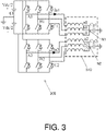
- FIGs. 3 , 4 show six-phase voltage source inverters (VSIs) 305, 405 connected to six-phase machines 310, 410, together with the parasitic CM capacitors Cg1, Cg2, Cg.
- the inverter terminal voltages of each six-phase VSI 305, 405 are switching between positive and negative direct current link (Vdc/2 +, Vdc/2 -) and generating an EMI noise source.
- CM noises are conducted through the motor windings of the six-phase machines 310, 410 and the CM parasitic capacitors Cg1, Cg2, Cg to the respective grounds (e.g., during the zero common-mode pulse width modulation).
- the six-phase machine 310 illustrates the first configuration 200a with two separate neutral points N1, N2 for each group of windings.
- the six-phase machine 410 illustrates the second configuration 200b with a connected neutral point N3 for the windings.
- the CM capacitance of the parasitic CM capacitors Cg1, Cg2 are equal or substantially equal.
- the connected neutral point N3 With the connected neutral point N3, the CM capacitance is concentrated in the parasitic CM capacitor Cg.
- a parasitic capacitance between windings and ground can be modeled as one CM capacitor for common-neutral connection or two equal or substantially equal CM capacitors for separate neutral connection.
- a CM voltage for the six-phase voltage VSIs can be expressed in equation (1).
- V cm V A 1 + V A 2 + V B 1 + V B 2 + V C 1 + V C 2 6
- the drive and motor system can be driven by a six-phase power converter.
- the six-phase power converter includes at least one phase-leg of two switches connected to one phase of the six phase windings.
- the six-phase power converter can include twelve switches with a pair of switches connected to a respective one winding of the six phase windings.
- the switching pattern of the six-phase power converter can be arranged for at least two groups of windings, which are located in opposite position with each other, where the switching actions are complementary so that the CM voltage for a full motor drive is kept/maintained to be zero. In this way, a switching pattern is achieved when duty cycles and carriers for the first group of windings are reversed together with generating switching actions for the second group of windings.
- switch vectors are also calculated in equation(2), with equation (2a) for winding space distribution 500a and equation (2b) for winding space distribution 500b.
- ⁇ V x 1 , x 2 , x 3 * 1 , exp j 2 ⁇ / 3 , exp j 4 ⁇ / 3
- V x 1 , x 2 , x 3 * ⁇ 1 , exp ⁇ j ⁇ / 3 , exp j ⁇ / 3
- x1, x2 and x3 are a switching status of a phase-leg, which are either 1 or 0. With these two equations, the voltage vectors for the two groups of inverter phases are shown in FIG. 6 .
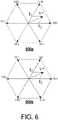
- FIG. 6 illustrates voltage vectors for groups of inverter phases.
- FIG. 6 includes a first formation 600a of 6 voltage vectors for the first group of phases and a second formation 600b of 6 voltage vectors for the second group of phases.
- the 6 voltage vectors of the second formation 600b are exactly opposite from the first formation 600a.
- the complementary voltage vector in the second group of phases will achieve the same effect with the original voltage vector in the first group of phases. Note that a zero voltage vector 111 and 000 in two groups of phases are complementary, too.
- CM negligible CM
- a calculation of the duty cycle (e.g., with a - 1 ⁇ 1 range) for the first group of phases is performed, while a duty cycle is directly reversed for the second group of phases.
- a triangle carrier for the second group of phases is also reversed with respect to a triangle carrier for the first group of phases.
- a first switching function for the first group of phases is generated in a first comparator, and a second switching function for the second group of phases is generated in comparator.
- a zero CM voltage is achieved.
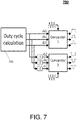
- FIG. 7 illustrates a pulse width modulation generation for a six-phase motor drive to achieve zero CM voltage.
- the duty cycle is directly reversed for da2, db2 and dc2.
- the triangle carrier for da2, db2 and dc2 are also reversed from that of da1, db1 and dc1.
- the switching function for first group of phases are generated in Comparator 1
- the switching function for the second group of phases are generated in Comparator 2.
- a general space vector PWM can be used in the duty cycle calculation in FIG. 7 .
- the duty cycles (-1 ⁇ 1) of the first group windings are calculated and sent to Comparator 1, while the reversed duty cycles are sent to Comparator 2.
- the CM voltage in N1 and N2 will be complementary to each other. In this way, the CM voltage will be zero for the full motor drive in the whole period. With zero CM voltage, a phase current can include even less ripple and similar harmonics of other drive and motor systems.
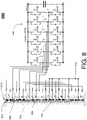
- FIG. 8 is schematic diagram of a linear propulsion system 800 according to one embodiment of the motor and drive system described above.
- the linear propulsion system 800 includes a drive 842 (e.g., embodiment of the six-phase VSI 305, 405), a section of the primary portion 816, and a secondary portion 818 of the linear propulsion system.
- the drive 842 is a two level, six phase drive, have six phase legs labeled A, B, C, D, E, and F. It is understood that the drive 842 may be three level, or N-level, and embodiments are not limited to 2-level drives.
- the primary portion 816 of the linear propulsion system 800 includes twelve coils 854 designated as A ⁇ , E, B, F ⁇ , C ⁇ , D, A, E ⁇ , B ⁇ , F, C and D ⁇ .
- the letter designates which phase the coil belongs to, and the presence or absence of the ⁇ indicates the current direction.
- a pair of coils 854 is associated with each phase (e.g., A and A ⁇ ). Current flow in coil A is in the opposite direction as current flow of coil A ⁇ .
- the primary portion 816 of the linear propulsion system can be core-less.
- the coils 854 of the primary portion 816 may be formed about ferromagnetic cores with concentric coils wound around primary teeth.
- the coils 854 may be also placed on a ferromagnetic flat support 850, forming toothless primary portion 816.
- the coils 854 of the primary portion 816 are arranged in a star configuration, where coils for each phase (e.g., A and A ⁇ ) are in electrical series from a respective phase leg of the drive 842 to a neutral point 858. It is understood that other coil configurations may be utilized other than star configuration.
- the secondary portion 818 of the linear propulsion system 800 includes twenty two magnetic poles 856.
- the magnetic poles 856 may be arranged as shown in FIG. 8 using twenty two permanent magnets, arranged in alternating polarity facing the primary portion 716. In other embodiments, the twenty two magnetic poles 856 may be arranged as part of a Halbach array.
- the spacing of the permanent magnets or poles 856 e.g., center-to-center
- the spacing of the coils 854 e.g., center-to-center
- the ratio of the magnetic pole pitch to the coil pitch equals 6/11.
- Permanent magnets of the secondary portion 818 may be mounted on a ferromagnetic flat support 852. The secondary portion 818 may be positioned on one side of primary portion 816, or on both sides of the primary portion 816.
- FIG. 8 depicts twelve coils and twenty two magnetic poles
- the linear propulsion system may be generalized as having 12N coils and 22N magnetic poles, where N is a positive integer.
- the technical effects and benefits of embodiments of the drive and motor system include eliminating common-mode voltage for the inverter output, significant reductions of CM EMI noise and CM current, eliminating a need for extra coupling inductors, reduction of damage of CM current to the motor insulation and bearing.
- the technical effects and benefits of embodiments can include a six-phase voltage source inverter that eliminates a need for extra hardware modification due to the drive being based on a normal six-phase VSI, such as elimination of CM filter which in turn significantly increases power density, along with no need for a coupling inductor.
- technical effects and benefits of embodiments can include a six-phase machine with separate neutral connection or with a six-phase machine with common neutral connection.
Description
- The subject matter disclosed herein relates generally to the field of elevators, and more particularly to a multicar, ropeless elevator system.
- Ropeless elevator systems, also referred to as self-propelled elevator systems, are useful in certain applications (e.g., high rise buildings) where the mass of the ropes for a roped system is prohibitive and there is a desire for multiple elevator cars to travel in a single lane. There exist ropeless elevator systems in which a first lane is designated for upward traveling elevator cars and a second lane is designated for downward traveling elevator cars. A transfer station at each end of the hoistway is used to move cars horizontally between the first lane and second lane. XP010248630 ("An Inverter/Motor Drive With Common Mode Voltage Elimination") describes an inverter/motor drive topology and control strategy which serves to virtually eliminate common mode voltage and includes a six pole inverter. The international patent application
WO2014182272A1 discloses a ropeless elevator system having the features of the preambles of the appended independent claims. - According to the invention, there is disclosed a ropeless elevator system, including a motor and drive system, in accordance with
claim 1. - In the above embodiment, or in the alternative, common-mode noises can be conducted through the six phase windings of the six-phase machine through at least one parasitic capacitor to a ground during the zero common-mode pulse width modulation.
- In the above embodiments, or in the alternative, the six phase windings can be distributed at a 60 degrees difference in space.
- In the above embodiments, or in the alternative, the each windings group can form a three-phase, 1200 phase-shift machine.
- In the above embodiments, or in the alternative, the six phase windings can include at least two separate neutral connections, where a maximum modulation index is approximate to 1.15.
- In the above embodiments, or in the alternative, a parasitic capacitance between windings and ground can be modeled as one common-mode capacitor for a common-neutral connection or two equal or substantially equal common-mode capacitors for two separate neutral connections.
- In the above embodiments, or in the alternative, the six phase windings can include a common neutral connection, where a maximum modulation index is 1.
- In the above embodiments, or in the alternative, the at least one parasitic capacitor can be a single parasitic common-mode capacitors that concentrates a common-mode capacitance from a common neutral connection.
- The motor and drive system comprises a six-phase power converter configured to drive the motor and drive system, wherein the six-phase power converter includes one phase-leg of two switches connected to one phase of the six phase windings
- In the above embodiments, or in the alternative, the six-phase power converter can include twelve switches.
- A switching pattern of the six-phase power converter is arranged for the at least two windings groups.
- Switching actions of the switching pattern are complementary for the at least two windings groups to maintain a common-mode voltage at zero.
- In the above embodiments, or in the alternative, the switching pattern can be generated by reversing duty cycles and carriers for a first group of the at least two windings groups when generating switching actions for a second group of the at least two windings groups.
- In the above embodiments, the motor and drive system is included in a ropeless elevator system.
- According to the invention, there is disclosed a method in accordance with
claim 11. - Additional features and advantages are realized through the techniques of the present disclosure. Other embodiments and aspects of the disclosure are described in detail herein. For a better understanding of the disclosure with the advantages and the features, refer to the description and to the drawings.
- The subject matter which is regarded as the invention is particularly pointed out and distinctly claimed in the independent claims at the conclusion of the specification. The foregoing and other features, and advantages of the invention are apparent from the following detailed description taken in conjunction with the accompanying drawings in which:
-
FIG. 1 depicts a multicar elevator system in an exemplary embodiment; -
FIG. 2 shows of six-phase machine winding configurations in accordance with embodiments of the present invention; -
FIG. 3 illustrates a six-phase voltage source inverter with six-phase machine according to an embodiment of the invention; -
FIG. 4 illustrates another six-phase voltage source inverter with six-phase machine according to another embodiment of the invention; -
FIG. 5 illustrates configurations of windings in six-phase machine space in accordance with embodiments of the present invention; -
FIG. 6 illustrates voltage vectors for groups of inverter phases in accordance with embodiments of the present invention; -
FIG. 7 illustrates a pulse width modulation generation for a six-phase motor drive according to an embodiment of the invention; and -
FIG. 8 depicts a drive and a section of the primary portion and the secondary portion of a linear propulsion system in an exemplary embodiment. -
FIG. 1 depicts a multicar,ropeless elevator system 10 in an exemplary embodiment.Elevator system 10 includes ahoistway 11 having a plurality oflanes FIG. 1 , it is understood that embodiments may be used with multicar ropeless elevator systems that have any number of lanes. In eachlane cars 14 travel in one direction, i.e., up or down. For example, inFIG. 1 cars 14 inlanes cars 14 inlane 17 travel down. One ormore cars 14 may travel in asingle lane - Above the top floor is an
upper transfer station 30 to impart horizontal motion toelevator cars 14 to moveelevator cars 14 betweenlanes upper transfer station 30 may be located at the top floor, rather than above the top floor. Below the first floor is alower transfer station 32 to impart horizontal motion toelevator cars 14 to moveelevator cars 14 betweenlanes lower transfer station 32 may be located at the first floor, rather than below the first floor. Although not shown inFIG. 1 , one or more intermediate transfer stations may be used between the first floor and the top floor. Intermediate transfer stations are similar to theupper transfer station 30 andlower transfer station 32. -
Cars 14 are propelled using a motor and drive system (e.g., a linear motor system) having a primary, fixedportion 16 and a secondary, movingportion 18. Theprimary portion 16 includes windings or coils mounted at one or both sides of thelanes Secondary portion 18 includes permanent magnets mounted to one or both sides ofcars 14.Primary portion 16 is supplied with drive signals to control movement ofcars 14 in their respective lanes. - The linear motor system of the ropeless elevator system can employ a power electronics inverter (e.g., as variable speed alternating drive (AC) motor drive) to improve the performance of the linear motor system. However, switching of power electronics devices in the motor drive includes inherent electromagnetic interference (EMI) problems. In general, EMI noise can be divided into two major groups: differential mode (DM) noise and common-mode (CM) noise. DM noises are conducted between phases. CM noises are conducted together with all phases through the parasitic capacitors to the ground. CM noises are with serious concern for motor drives because CM noises increase the EMI in the motor drive and damage the motor bearing and winding insulation. Unfortunately, solutions such as adding CM filters to attenuate CM noises are not viable in the linear motor system of the
ropeless elevator system 10 due to the significant weight penalty of each CM filter significantly increase. - In view of the above, embodiments of the present invention set forth a drive and motor system and/or method for a six phase machine with negligible CM voltage. The six-phase machine includes six phase windings.
FIG. 2 illustrates six-phasemachine winding configuration - Further, embodiments of the drive and motor system can utilize the six-phase machine with a separate neutral connection or a common neutral connection, where a maximum modulation index can be approximate to 1.15 (e.g., wherein an exact value is 2/sqrt(3)) with separate neutral connection and a maximum modulation index can be approximate to 1 with common neutral connection. For example, in the
first configuration 200a, two neutral points N1, N2 for the two groups of windings can be separated. In thesecond configuration 200b, the neutral points for the two groups of windings are connected at neutral point N3. - The six-phase machine is also in electrical communication with a six phase inverter. In general, to produce a zero CM pulse width modulation (PWM), a space vector combination can be calculated with a first group of phases and be substantially or directly matched to complementary voltage vectors for a second group of phases. Note that, while the producing the zero CM PWM for the two groups of windings, the six phase windings may be divided into any number of groups. Further, the zero CM PWM is an active control signal produced by the drive and motor system (e.g., result in a zero common-mode pulse width modulation across the at least two windings groups).
-
FIGs. 3 ,4 show six-phase voltage source inverters (VSIs) 305, 405 connected to six-phase machines phase VSI phase machines - The six-
phase machine 310 illustrates thefirst configuration 200a with two separate neutral points N1, N2 for each group of windings. The six-phase machine 410 illustrates thesecond configuration 200b with a connected neutral point N3 for the windings. With the separate neutral points N1, N2, the CM capacitance of the parasitic CM capacitors Cg1, Cg2 are equal or substantially equal. With the connected neutral point N3, the CM capacitance is concentrated in the parasitic CM capacitor Cg. In this way, a parasitic capacitance between windings and ground can be modeled as one CM capacitor for common-neutral connection or two equal or substantially equal CM capacitors for separate neutral connection. In both cases, a CM voltage for the six-phase voltage VSIs can be expressed in equation (1).
- The drive and motor system can be driven by a six-phase power converter. The six-phase power converter includes at least one phase-leg of two switches connected to one phase of the six phase windings. In some embodiments, the six-phase power converter can include twelve switches with a pair of switches connected to a respective one winding of the six phase windings. The switching pattern of the six-phase power converter can be arranged for at least two groups of windings, which are located in opposite position with each other, where the switching actions are complementary so that the CM voltage for a full motor drive is kept/maintained to be zero. In this way, a switching pattern is achieved when duty cycles and carriers for the first group of windings are reversed together with generating switching actions for the second group of windings.
- As shown in
FIG. 5 , based on the two windingspace distribution space distribution 500a and equation (2b) for windingspace distribution 500b.
- In equation (2), x1, x2 and x3 are a switching status of a phase-leg, which are either 1 or 0. With these two equations, the voltage vectors for the two groups of inverter phases are shown in
FIG. 6 . -
FIG. 6 illustrates voltage vectors for groups of inverter phases.FIG. 6 includes afirst formation 600a of 6 voltage vectors for the first group of phases and asecond formation 600b of 6 voltage vectors for the second group of phases. The 6 voltage vectors of thesecond formation 600b are exactly opposite from thefirst formation 600a. In turn, the complementary voltage vector in the second group of phases will achieve the same effect with the original voltage vector in the first group of phases. Note that a zero voltage vector 111 and 000 in two groups of phases are complementary, too. - To produce the negligible CM, a calculation of the duty cycle (e.g., with a - 1~1 range) for the first group of phases is performed, while a duty cycle is directly reversed for the second group of phases. A triangle carrier for the second group of phases is also reversed with respect to a triangle carrier for the first group of phases. Then, a first switching function for the first group of phases is generated in a first comparator, and a second switching function for the second group of phases is generated in comparator. In turn, when the first and second switching functions are combined, a zero CM voltage is achieved.
- For example,
FIG. 7 illustrates a pulse width modulation generation for a six-phase motor drive to achieve zero CM voltage. After calculation of the duty cycle calculation 705 (-1~1 range) of da1, db1 and dc1 for the first group of phases, the duty cycle is directly reversed for da2, db2 and dc2. The triangle carrier for da2, db2 and dc2 are also reversed from that of da1, db1 and dc1. Then, the switching function for first group of phases are generated inComparator 1, and the switching function for the second group of phases are generated inComparator 2. - With separate neutral points N1, N2 in
FIG. 3 , a general space vector PWM can be used in the duty cycle calculation inFIG. 7 . In this way, the duty cycles (-1~1) of the first group windings are calculated and sent toComparator 1, while the reversed duty cycles are sent toComparator 2. Then the CM voltage in N1 and N2 will be complementary to each other. In this way, the CM voltage will be zero for the full motor drive in the whole period. With zero CM voltage, a phase current can include even less ripple and similar harmonics of other drive and motor systems. -
FIG. 8 is schematic diagram of alinear propulsion system 800 according to one embodiment of the motor and drive system described above. Thelinear propulsion system 800 includes a drive 842 (e.g., embodiment of the six-phase VSI 305, 405), a section of theprimary portion 816, and asecondary portion 818 of the linear propulsion system. Thedrive 842 is a two level, six phase drive, have six phase legs labeled A, B, C, D, E, and F. It is understood that thedrive 842 may be three level, or N-level, and embodiments are not limited to 2-level drives. In the depicted embodiment, theprimary portion 816 of thelinear propulsion system 800 includes twelvecoils 854 designated as A∗, E, B, F∗, C∗, D, A, E∗, B∗, F, C and D∗. The letter designates which phase the coil belongs to, and the presence or absence of the ∗ indicates the current direction. A pair ofcoils 854 is associated with each phase (e.g., A and A∗). Current flow in coil A is in the opposite direction as current flow of coil A∗. Theprimary portion 816 of the linear propulsion system can be core-less. Alternatively, thecoils 854 of theprimary portion 816 may be formed about ferromagnetic cores with concentric coils wound around primary teeth. Thecoils 854 may be also placed on a ferromagneticflat support 850, forming toothlessprimary portion 816. - The
coils 854 of theprimary portion 816 are arranged in a star configuration, where coils for each phase (e.g., A and A∗) are in electrical series from a respective phase leg of thedrive 842 to aneutral point 858. It is understood that other coil configurations may be utilized other than star configuration. - The
secondary portion 818 of thelinear propulsion system 800 includes twenty twomagnetic poles 856. Themagnetic poles 856 may be arranged as shown inFIG. 8 using twenty two permanent magnets, arranged in alternating polarity facing the primary portion 716. In other embodiments, the twenty twomagnetic poles 856 may be arranged as part of a Halbach array. The spacing of the permanent magnets or poles 856 (e.g., center-to-center) is referred to as the pole pitch. The spacing of the coils 854 (e.g., center-to-center) is referred to as the coil pitch. The ratio of the magnetic pole pitch to the coil pitch equals 6/11. Permanent magnets of thesecondary portion 818 may be mounted on a ferromagneticflat support 852. Thesecondary portion 818 may be positioned on one side ofprimary portion 816, or on both sides of theprimary portion 816. - Although
FIG. 8 depicts twelve coils and twenty two magnetic poles, the linear propulsion system may be generalized as having 12N coils and 22N magnetic poles, where N is a positive integer. - In view of the above, the technical effects and benefits of embodiments of the drive and motor system include eliminating common-mode voltage for the inverter output, significant reductions of CM EMI noise and CM current, eliminating a need for extra coupling inductors, reduction of damage of CM current to the motor insulation and bearing. Further, the technical effects and benefits of embodiments can include a six-phase voltage source inverter that eliminates a need for extra hardware modification due to the drive being based on a normal six-phase VSI, such as elimination of CM filter which in turn significantly increases power density, along with no need for a coupling inductor. Furthermore, technical effects and benefits of embodiments can include a six-phase machine with separate neutral connection or with a six-phase machine with common neutral connection.
Claims (11)
- A ropeless elevator system (10) comprising a motor and drive system, said motor and drive system comprising:at least one direct current source (Vdc/2 +, Vdc/2 -);a six phase inverter (305, 405) switching between positive and negative power of the at least one direct current source; anda six phase machine (310, 410) including six phase windings (a1, b1, c1, a2, b2, c2) divided into at least two windings groups (a1, b1, c1; a2, b2, c2); anda six-phase power converter configured to drive the motor and drive system;characterized in that:the six-phase power converter includes one phase-leg of two switches connected to one phase of the six phase windings;wherein the motor and drive system is arranged to produce an active control signal, said active control signal being configured to result in a zero common-mode pulse width modulation across the at least two windings groups (a1, b1, c1; a2, b2, c2);wherein a switching pattern of the six-phase power converter is arranged for the at least two windings groups (a1, b1, c1; a2, b2, c2); andwherein the switching actions of the switching pattern are complementary for the at least two windings groups (a1, b1, c1; a2, b2, c2) to maintain a common-mode voltage at zero.
- The ropeless elevator system (10) of any preceding claim, wherein common-mode noises are conducted through the six phase windings of the six-phase machine (310, 410) through at least one parasitic capacitor (Cg, Cg1, Cg2) to a ground during the zero common-mode pulse width modulation.
- The ropeless elevator system (10) of any preceding claim, wherein the six phase windings (a1, b1, c1; a2, b2, c2) are distributed at a 60 degrees difference in space.
- The ropeless elevator system (10) of any preceding claim, wherein the each windings group (a1, b1, c1; a2, b2, c2) forms a three-phase, 1200 phase-shift machine.
- The ropeless elevator system (10) of any preceding claim, wherein the six phase windings (a1, b1, c1, a2, b2, c2) include at least two separate neutral connections (N1, N2), where a maximum modulation index is approximate to 1.15.
- The ropeless elevator system (10) of any preceding claim, wherein a parasitic capacitance between windings (a1, b1, c1, a2, b2, c2) and ground is modeled as one common-mode capacitor for a common-neutral connection or two substantially equal common-mode capacitors (Cg1, Cg2) for two separate neutral connections (N1, N2).
- The ropeless elevator system (10) of claims 1, 2, 3, and 4 wherein the six phase windings include a common neutral connection (N3), where a maximum modulation index is 1.
- The ropeless elevator system (10) of claim 2, wherein the at least one parasitic capacitor is a single parasitic common-mode capacitor (Cg) that concentrates a common-mode capacitance from a common neutral connection (N3).
- The ropeless elevator system (10) of any preceding claim, wherein the six-phase power converter includes twelve switches.
- The ropeless elevator system (10) of any preceding claim, wherein the switching pattern is generated by reversing duty cycles and carriers for a first group (a1, b1, c1) of the at least two windings groups when generating switching actions for a second group (a2, b2, c2) of the at least two windings groups (a1, b1, c1; a2, b2, c2).
- A method of operating a ropeless elevator system (10) comprising a motor and drive system, the method comprising:switching, by a six phase inverter (305, 405) of the motor and drive system, between positive and negative power of at least one direct current source (Vdc/2 +, Vdc/2 -);the motor and drive system producing an active control signal, said active control signal effecting a zero common-mode pulse width modulation across at least two windings groups (a1, b1, c1; a2, b2, c2), by a six phase machine (310, 410), in accordance with the switching by the six phase inverter (305, 405), the six phase machine (310, 410) including six phase windings (a1, b1, c1, a2, b2, c2) divided into the at least two windings groups (a1, b1, c1; a2, b2, c2); anddriving the motor and drive system using a six-phase power converter;characterized in that:the six-phase power converter includes one phase-leg of two switches connected to one phase of the six phase windings, wherein a switching pattern of the six-phase power converter is arranged for the at least two windings groups (a1, b1, c1; a2, b2, c2);wherein the switching actions of the switching pattern are complementary for the at least two windings groups (a1, b1, c1; a2, b2, c2) to maintain a common-mode voltage at zero.
Priority Applications (1)
| Application Number | Priority Date | Filing Date | Title |
|---|---|---|---|
| EP22215410.6A EP4195498A3 (en) | 2015-02-05 | 2016-02-03 | Drive and control for six-phase electrical machines with negligible common-mode voltage |
Applications Claiming Priority (2)
| Application Number | Priority Date | Filing Date | Title |
|---|---|---|---|
| US201562112272P | 2015-02-05 | 2015-02-05 | |
| PCT/US2016/016308 WO2016126782A1 (en) | 2015-02-05 | 2016-02-03 | Drive and control for six-phase electrical machines with negligible common-mode voltage |
Related Child Applications (1)
| Application Number | Title | Priority Date | Filing Date |
|---|---|---|---|
| EP22215410.6A Division EP4195498A3 (en) | 2015-02-05 | 2016-02-03 | Drive and control for six-phase electrical machines with negligible common-mode voltage |
Publications (2)
| Publication Number | Publication Date |
|---|---|
| EP3254372A1 EP3254372A1 (en) | 2017-12-13 |
| EP3254372B1 true EP3254372B1 (en) | 2022-12-28 |
Family
ID=55453270
Family Applications (2)
| Application Number | Title | Priority Date | Filing Date |
|---|---|---|---|
| EP16708001.9A Active EP3254372B1 (en) | 2015-02-05 | 2016-02-03 | Drive and control for six-phase electrical machines with negligible common-mode voltage |
| EP22215410.6A Pending EP4195498A3 (en) | 2015-02-05 | 2016-02-03 | Drive and control for six-phase electrical machines with negligible common-mode voltage |
Family Applications After (1)
| Application Number | Title | Priority Date | Filing Date |
|---|---|---|---|
| EP22215410.6A Pending EP4195498A3 (en) | 2015-02-05 | 2016-02-03 | Drive and control for six-phase electrical machines with negligible common-mode voltage |
Country Status (5)
| Country | Link |
|---|---|
| US (1) | US10773922B2 (en) |
| EP (2) | EP3254372B1 (en) |
| KR (1) | KR102587874B1 (en) |
| CN (1) | CN107223307B (en) |
| WO (1) | WO2016126782A1 (en) |
Families Citing this family (12)
| Publication number | Priority date | Publication date | Assignee | Title |
|---|---|---|---|---|
| WO2015084365A1 (en) * | 2013-12-05 | 2015-06-11 | Otis Elevator Company | Motor drive for linear machines with distributed windings |
| US10773922B2 (en) * | 2015-02-05 | 2020-09-15 | Otis Elevator Company | Drive and control for six-phase electrical machines with negligible common-mode voltage |
| US9985566B2 (en) * | 2015-05-29 | 2018-05-29 | Otis Elevator Company | Dual three-phase electrical machine and drive with negligible common-mode noise |
| CN108349703B (en) * | 2015-08-07 | 2020-12-01 | 奥的斯电梯公司 | Elevator linear propulsion system with cooling device |
| EP3574579B1 (en) | 2017-01-30 | 2023-11-08 | Carrier Corporation | Paralleled passive front-end rectifiers with and without interleaving |
| WO2018140757A1 (en) | 2017-01-30 | 2018-08-02 | Carrier Corporation | Method of controlling paralleled passive front-end rectifiers with and without interleaving |
| US9906183B1 (en) * | 2017-01-30 | 2018-02-27 | Otis Elevator Company | Parallel interleaved 2-level or 3-level regenerative drives |
| CN110011581B (en) * | 2019-01-28 | 2020-11-24 | 华中科技大学 | Method and system for suppressing common-mode noise of asymmetric six-phase alternating-current motor |
| US11527942B2 (en) * | 2019-03-27 | 2022-12-13 | National Technology & Engineering Solutions Of Sandia, Llc | Excitation control of dual-wound machines for coupling mitigation |
| DE102019110269A1 (en) * | 2019-04-18 | 2020-10-22 | Bayerische Motoren Werke Aktiengesellschaft | Method for controlling a multiphase electrical machine by means of space vector modulation, control device and drive arrangement |
| US11777437B2 (en) | 2019-07-25 | 2023-10-03 | Cummins Inc. | Fault tolerant operations of a six-phase machine |
| GB2615762A (en) * | 2022-02-16 | 2023-08-23 | Mercedes Benz Group Ag | A method for controlling a six-phase electric motor by a control system |
Citations (1)
| Publication number | Priority date | Publication date | Assignee | Title |
|---|---|---|---|---|
| US20140111066A1 (en) * | 2012-10-23 | 2014-04-24 | Hitachi, Ltd. | Rotary machine and drive system therefor |
Family Cites Families (31)
| Publication number | Priority date | Publication date | Assignee | Title |
|---|---|---|---|---|
| US3819992A (en) * | 1972-01-21 | 1974-06-25 | Power Control Corp | Method and apparatus for providing efficient and stable power inversion with voltage and frequency control |
| US4511834A (en) * | 1982-12-23 | 1985-04-16 | Borg-Warner Corporation | Control and stabilizing system for damperless synchronous motor |
| JP3399134B2 (en) * | 1994-12-12 | 2003-04-21 | 株式会社明電舎 | Operation control device for pole number switching motor |
| US5852558A (en) * | 1997-06-20 | 1998-12-22 | Wisconsin Alumni Research Foundation | Method and apparatus for reducing common mode voltage in multi-phase power converters |
| US5905644A (en) * | 1998-07-31 | 1999-05-18 | Allen-Bradley Company, Llc | DC bus voltage controller |
| JP3711956B2 (en) * | 2002-04-01 | 2005-11-02 | 日産自動車株式会社 | Driving method of rotating electric machine |
| DE10301275B4 (en) * | 2003-01-15 | 2016-06-16 | Siemens Aktiengesellschaft | Method for reducing common-mode parasitic currents in an electric drive system and corresponding electric drive system |
| JP4339757B2 (en) * | 2004-07-12 | 2009-10-07 | 株式会社日立製作所 | Vehicle drive power generation system |
| GB0422201D0 (en) * | 2004-10-07 | 2004-11-03 | Trw Ltd | Motor drive control |
| US7663268B2 (en) * | 2006-08-30 | 2010-02-16 | The Regents of the University of Cailfornia | Converters for high power applications |
| US7990098B2 (en) * | 2007-07-30 | 2011-08-02 | GM Global Technology Operations LLC | Series-coupled two-motor drive using double-ended inverter system |
| US7884562B2 (en) * | 2007-10-26 | 2011-02-08 | Frederick William Klatt | Brushless multiphase self-commutation controller |
| JP4450082B2 (en) * | 2008-03-10 | 2010-04-14 | トヨタ自動車株式会社 | Electric motor drive device and control method thereof |
| US8415904B2 (en) * | 2010-06-29 | 2013-04-09 | Ac Propulsion, Inc. | Open delta motor drive with integrated recharge |
| FR3004299B1 (en) * | 2013-04-05 | 2016-10-28 | Valeo Equip Electr Moteur | METHOD AND DEVICE FOR CONTROLLING A POLYPHASE INVERTER |
| WO2014182272A1 (en) | 2013-05-06 | 2014-11-13 | Otis Elevator Company | Linear motor stator core for self-propelled elevator |
| DE102013208544A1 (en) * | 2013-05-08 | 2014-11-13 | Lenze Drives Gmbh | drive system |
| US9533638B2 (en) * | 2013-07-18 | 2017-01-03 | The Boeing Company | Aircraft universal power converter |
| FR3015145B1 (en) * | 2013-12-18 | 2017-07-07 | Thales Sa | MODULAR AND RECONFIGURABLE ELECTRIC POWER CONVERTING DEVICE |
| US20150349598A1 (en) * | 2014-05-28 | 2015-12-03 | Hamilton Sundstrand Corporation | Multiplex winding synchronous generator |
| JP6501507B2 (en) * | 2014-06-02 | 2019-04-17 | 株式会社小松製作所 | Control device for rotating electric machine and rotating electric machine |
| US10773922B2 (en) * | 2015-02-05 | 2020-09-15 | Otis Elevator Company | Drive and control for six-phase electrical machines with negligible common-mode voltage |
| US9985566B2 (en) * | 2015-05-29 | 2018-05-29 | Otis Elevator Company | Dual three-phase electrical machine and drive with negligible common-mode noise |
| US9893604B2 (en) * | 2015-07-21 | 2018-02-13 | Robert W. Horst | Circuit with low DC bias storage capacitors for high density power conversion |
| US10727774B2 (en) * | 2016-03-11 | 2020-07-28 | General Atomics | Multi-level high-speed adjustable speed drive |
| US10396694B2 (en) * | 2016-03-17 | 2019-08-27 | General Electric Company | System and method for minimizing reactive current to limit rotor modulation index on a power converter |
| DE112016007043B4 (en) * | 2016-07-04 | 2022-03-10 | Mitsubishi Electric Corporation | POLE-VARIABLE ROTATING ELECTRICAL MACHINE AND DRIVE METHOD FOR POLE-VARIABLE ROTATING ELECTRICAL MACHINE |
| US10063161B2 (en) * | 2016-10-18 | 2018-08-28 | Abb Schweiz Ag | Active neutral point clamped converter control system and method |
| CN108233755B (en) * | 2018-02-12 | 2020-01-31 | 武汉大学 | space vector pulse width modulation method for inhibiting common-mode voltage of multi-phase motor |
| US11239717B2 (en) * | 2018-06-11 | 2022-02-01 | North Carolina State University | AC machine windings |
| US10525843B1 (en) * | 2018-06-19 | 2020-01-07 | Ford Global Technologies, Llc | Common mode current reduction hybrid drive system |
-
2016
- 2016-02-03 US US15/549,076 patent/US10773922B2/en active Active
- 2016-02-03 WO PCT/US2016/016308 patent/WO2016126782A1/en active Application Filing
- 2016-02-03 EP EP16708001.9A patent/EP3254372B1/en active Active
- 2016-02-03 CN CN201680008952.5A patent/CN107223307B/en active Active
- 2016-02-03 EP EP22215410.6A patent/EP4195498A3/en active Pending
- 2016-02-03 KR KR1020177024668A patent/KR102587874B1/en active IP Right Grant
Patent Citations (1)
| Publication number | Priority date | Publication date | Assignee | Title |
|---|---|---|---|---|
| US20140111066A1 (en) * | 2012-10-23 | 2014-04-24 | Hitachi, Ltd. | Rotary machine and drive system therefor |
Also Published As
| Publication number | Publication date |
|---|---|
| EP3254372A1 (en) | 2017-12-13 |
| CN107223307B (en) | 2020-12-08 |
| CN107223307A (en) | 2017-09-29 |
| EP4195498A3 (en) | 2023-08-02 |
| KR20170115568A (en) | 2017-10-17 |
| US10773922B2 (en) | 2020-09-15 |
| EP4195498A2 (en) | 2023-06-14 |
| KR102587874B1 (en) | 2023-10-11 |
| WO2016126782A1 (en) | 2016-08-11 |
| US20180022576A1 (en) | 2018-01-25 |
Similar Documents
| Publication | Publication Date | Title |
|---|---|---|
| EP3254372B1 (en) | Drive and control for six-phase electrical machines with negligible common-mode voltage | |
| US9985566B2 (en) | Dual three-phase electrical machine and drive with negligible common-mode noise | |
| EP2999652B1 (en) | Self-propelled elevator with wireless power supply | |
| EP2950440B1 (en) | Pulse-width modulation control of paralleled inverters | |
| EP2950434A1 (en) | Output filter with interphase reactor for paralleled inverters | |
| CN106487200B (en) | Electromagnetic propulsion system with wireless power transfer system | |
| US20170057791A1 (en) | Elevator wireless power supply | |
| EP3104517A2 (en) | Paralleled active front-end rectifiers with negligible common-mode | |
| CN102810923A (en) | Electric drive with electronically scalable reconfigurable winding | |
| CN105324323B (en) | Self-propelled elevator device with the winding proportional to car speed | |
| US20210135558A1 (en) | Linear motor and transport system using the same | |
| US20180002142A1 (en) | Six-phase motor for elevator system | |
| JP4838031B2 (en) | Multiple inverter control system | |
| EP4084324A1 (en) | Rotary electric machine control device | |
| CN111106732B (en) | Linear motor and primary winding thereof | |
| Goodman et al. | DC side ripple cancellation in a cascaded multi-level topology for automotive applications | |
| Arashloo et al. | Ripple free fault tolerant control of five phase permanent magnet machines | |
| JP6104731B2 (en) | Electric vehicle control device and electric vehicle control system | |
| CN219535866U (en) | Ultra-high-speed phase-change number linear motor and rail transit system with same | |
| Vafakhah | Multilevel space vector PWM for multilevel coupled inductor inverters | |
| RU1635866C (en) | Method of controlling asynchronous electric motor | |
| Maandi et al. | Minimizing torque ripple and copper losses in variable speed brushless DC motor |
Legal Events
| Date | Code | Title | Description |
|---|---|---|---|
| STAA | Information on the status of an ep patent application or granted ep patent |
Free format text: STATUS: THE INTERNATIONAL PUBLICATION HAS BEEN MADE |
|
| PUAI | Public reference made under article 153(3) epc to a published international application that has entered the european phase |
Free format text: ORIGINAL CODE: 0009012 |
|
| STAA | Information on the status of an ep patent application or granted ep patent |
Free format text: STATUS: REQUEST FOR EXAMINATION WAS MADE |
|
| 17P | Request for examination filed |
Effective date: 20170904 |
|
| AK | Designated contracting states |
Kind code of ref document: A1 Designated state(s): AL AT BE BG CH CY CZ DE DK EE ES FI FR GB GR HR HU IE IS IT LI LT LU LV MC MK MT NL NO PL PT RO RS SE SI SK SM TR |
|
| AX | Request for extension of the european patent |
Extension state: BA ME |
|
| DAV | Request for validation of the european patent (deleted) | ||
| DAX | Request for extension of the european patent (deleted) | ||
| STAA | Information on the status of an ep patent application or granted ep patent |
Free format text: STATUS: EXAMINATION IS IN PROGRESS |
|
| 17Q | First examination report despatched |
Effective date: 20190626 |
|
| STAA | Information on the status of an ep patent application or granted ep patent |
Free format text: STATUS: EXAMINATION IS IN PROGRESS |
|
| STAA | Information on the status of an ep patent application or granted ep patent |
Free format text: STATUS: EXAMINATION IS IN PROGRESS |
|
| GRAP | Despatch of communication of intention to grant a patent |
Free format text: ORIGINAL CODE: EPIDOSNIGR1 |
|
| STAA | Information on the status of an ep patent application or granted ep patent |
Free format text: STATUS: GRANT OF PATENT IS INTENDED |
|
| INTG | Intention to grant announced |
Effective date: 20220708 |
|
| GRAS | Grant fee paid |
Free format text: ORIGINAL CODE: EPIDOSNIGR3 |
|
| GRAA | (expected) grant |
Free format text: ORIGINAL CODE: 0009210 |
|
| STAA | Information on the status of an ep patent application or granted ep patent |
Free format text: STATUS: THE PATENT HAS BEEN GRANTED |
|
| AK | Designated contracting states |
Kind code of ref document: B1 Designated state(s): AL AT BE BG CH CY CZ DE DK EE ES FI FR GB GR HR HU IE IS IT LI LT LU LV MC MK MT NL NO PL PT RO RS SE SI SK SM TR |
|
| REG | Reference to a national code |
Ref country code: GB Ref legal event code: FG4D |
|
| REG | Reference to a national code |
Ref country code: CH Ref legal event code: EP |
|
| REG | Reference to a national code |
Ref country code: DE Ref legal event code: R096 Ref document number: 602016077103 Country of ref document: DE |
|
| REG | Reference to a national code |
Ref country code: AT Ref legal event code: REF Ref document number: 1541094 Country of ref document: AT Kind code of ref document: T Effective date: 20230115 |
|
| REG | Reference to a national code |
Ref country code: IE Ref legal event code: FG4D |
|
| REG | Reference to a national code |
Ref country code: LT Ref legal event code: MG9D |
|
| PG25 | Lapsed in a contracting state [announced via postgrant information from national office to epo] |
Ref country code: SE Free format text: LAPSE BECAUSE OF FAILURE TO SUBMIT A TRANSLATION OF THE DESCRIPTION OR TO PAY THE FEE WITHIN THE PRESCRIBED TIME-LIMIT Effective date: 20221228 Ref country code: NO Free format text: LAPSE BECAUSE OF FAILURE TO SUBMIT A TRANSLATION OF THE DESCRIPTION OR TO PAY THE FEE WITHIN THE PRESCRIBED TIME-LIMIT Effective date: 20230328 Ref country code: LT Free format text: LAPSE BECAUSE OF FAILURE TO SUBMIT A TRANSLATION OF THE DESCRIPTION OR TO PAY THE FEE WITHIN THE PRESCRIBED TIME-LIMIT Effective date: 20221228 Ref country code: FI Free format text: LAPSE BECAUSE OF FAILURE TO SUBMIT A TRANSLATION OF THE DESCRIPTION OR TO PAY THE FEE WITHIN THE PRESCRIBED TIME-LIMIT Effective date: 20221228 |
|
| PGFP | Annual fee paid to national office [announced via postgrant information from national office to epo] |
Ref country code: FR Payment date: 20230119 Year of fee payment: 8 |
|
| REG | Reference to a national code |
Ref country code: NL Ref legal event code: MP Effective date: 20221228 |
|
| REG | Reference to a national code |
Ref country code: AT Ref legal event code: MK05 Ref document number: 1541094 Country of ref document: AT Kind code of ref document: T Effective date: 20221228 |
|
| PG25 | Lapsed in a contracting state [announced via postgrant information from national office to epo] |
Ref country code: RS Free format text: LAPSE BECAUSE OF FAILURE TO SUBMIT A TRANSLATION OF THE DESCRIPTION OR TO PAY THE FEE WITHIN THE PRESCRIBED TIME-LIMIT Effective date: 20221228 Ref country code: LV Free format text: LAPSE BECAUSE OF FAILURE TO SUBMIT A TRANSLATION OF THE DESCRIPTION OR TO PAY THE FEE WITHIN THE PRESCRIBED TIME-LIMIT Effective date: 20221228 Ref country code: HR Free format text: LAPSE BECAUSE OF FAILURE TO SUBMIT A TRANSLATION OF THE DESCRIPTION OR TO PAY THE FEE WITHIN THE PRESCRIBED TIME-LIMIT Effective date: 20221228 Ref country code: GR Free format text: LAPSE BECAUSE OF FAILURE TO SUBMIT A TRANSLATION OF THE DESCRIPTION OR TO PAY THE FEE WITHIN THE PRESCRIBED TIME-LIMIT Effective date: 20230329 |
|
| PGFP | Annual fee paid to national office [announced via postgrant information from national office to epo] |
Ref country code: DE Payment date: 20230119 Year of fee payment: 8 |
|
| PG25 | Lapsed in a contracting state [announced via postgrant information from national office to epo] |
Ref country code: NL Free format text: LAPSE BECAUSE OF FAILURE TO SUBMIT A TRANSLATION OF THE DESCRIPTION OR TO PAY THE FEE WITHIN THE PRESCRIBED TIME-LIMIT Effective date: 20221228 |
|
| PG25 | Lapsed in a contracting state [announced via postgrant information from national office to epo] |
Ref country code: SM Free format text: LAPSE BECAUSE OF FAILURE TO SUBMIT A TRANSLATION OF THE DESCRIPTION OR TO PAY THE FEE WITHIN THE PRESCRIBED TIME-LIMIT Effective date: 20221228 Ref country code: RO Free format text: LAPSE BECAUSE OF FAILURE TO SUBMIT A TRANSLATION OF THE DESCRIPTION OR TO PAY THE FEE WITHIN THE PRESCRIBED TIME-LIMIT Effective date: 20221228 Ref country code: PT Free format text: LAPSE BECAUSE OF FAILURE TO SUBMIT A TRANSLATION OF THE DESCRIPTION OR TO PAY THE FEE WITHIN THE PRESCRIBED TIME-LIMIT Effective date: 20230428 Ref country code: ES Free format text: LAPSE BECAUSE OF FAILURE TO SUBMIT A TRANSLATION OF THE DESCRIPTION OR TO PAY THE FEE WITHIN THE PRESCRIBED TIME-LIMIT Effective date: 20221228 Ref country code: EE Free format text: LAPSE BECAUSE OF FAILURE TO SUBMIT A TRANSLATION OF THE DESCRIPTION OR TO PAY THE FEE WITHIN THE PRESCRIBED TIME-LIMIT Effective date: 20221228 Ref country code: CZ Free format text: LAPSE BECAUSE OF FAILURE TO SUBMIT A TRANSLATION OF THE DESCRIPTION OR TO PAY THE FEE WITHIN THE PRESCRIBED TIME-LIMIT Effective date: 20221228 Ref country code: AT Free format text: LAPSE BECAUSE OF FAILURE TO SUBMIT A TRANSLATION OF THE DESCRIPTION OR TO PAY THE FEE WITHIN THE PRESCRIBED TIME-LIMIT Effective date: 20221228 |
|
| PG25 | Lapsed in a contracting state [announced via postgrant information from national office to epo] |
Ref country code: SK Free format text: LAPSE BECAUSE OF FAILURE TO SUBMIT A TRANSLATION OF THE DESCRIPTION OR TO PAY THE FEE WITHIN THE PRESCRIBED TIME-LIMIT Effective date: 20221228 Ref country code: PL Free format text: LAPSE BECAUSE OF FAILURE TO SUBMIT A TRANSLATION OF THE DESCRIPTION OR TO PAY THE FEE WITHIN THE PRESCRIBED TIME-LIMIT Effective date: 20221228 Ref country code: IS Free format text: LAPSE BECAUSE OF FAILURE TO SUBMIT A TRANSLATION OF THE DESCRIPTION OR TO PAY THE FEE WITHIN THE PRESCRIBED TIME-LIMIT Effective date: 20230428 Ref country code: AL Free format text: LAPSE BECAUSE OF FAILURE TO SUBMIT A TRANSLATION OF THE DESCRIPTION OR TO PAY THE FEE WITHIN THE PRESCRIBED TIME-LIMIT Effective date: 20221228 |
|
| PG25 | Lapsed in a contracting state [announced via postgrant information from national office to epo] |
Ref country code: MC Free format text: LAPSE BECAUSE OF FAILURE TO SUBMIT A TRANSLATION OF THE DESCRIPTION OR TO PAY THE FEE WITHIN THE PRESCRIBED TIME-LIMIT Effective date: 20221228 |
|
| REG | Reference to a national code |
Ref country code: CH Ref legal event code: PL Ref country code: DE Ref legal event code: R097 Ref document number: 602016077103 Country of ref document: DE |
|
| REG | Reference to a national code |
Ref country code: BE Ref legal event code: MM Effective date: 20230228 |
|
| PG25 | Lapsed in a contracting state [announced via postgrant information from national office to epo] |
Ref country code: LU Free format text: LAPSE BECAUSE OF NON-PAYMENT OF DUE FEES Effective date: 20230203 Ref country code: LI Free format text: LAPSE BECAUSE OF NON-PAYMENT OF DUE FEES Effective date: 20230228 Ref country code: DK Free format text: LAPSE BECAUSE OF FAILURE TO SUBMIT A TRANSLATION OF THE DESCRIPTION OR TO PAY THE FEE WITHIN THE PRESCRIBED TIME-LIMIT Effective date: 20221228 Ref country code: CH Free format text: LAPSE BECAUSE OF NON-PAYMENT OF DUE FEES Effective date: 20230228 |
|
| PLBE | No opposition filed within time limit |
Free format text: ORIGINAL CODE: 0009261 |
|
| STAA | Information on the status of an ep patent application or granted ep patent |
Free format text: STATUS: NO OPPOSITION FILED WITHIN TIME LIMIT |
|
| GBPC | Gb: european patent ceased through non-payment of renewal fee |
Effective date: 20230328 |
|
| 26N | No opposition filed |
Effective date: 20230929 |
|
| REG | Reference to a national code |
Ref country code: IE Ref legal event code: MM4A |
|
| PG25 | Lapsed in a contracting state [announced via postgrant information from national office to epo] |
Ref country code: GB Free format text: LAPSE BECAUSE OF NON-PAYMENT OF DUE FEES Effective date: 20230328 |
|
| PG25 | Lapsed in a contracting state [announced via postgrant information from national office to epo] |
Ref country code: SI Free format text: LAPSE BECAUSE OF FAILURE TO SUBMIT A TRANSLATION OF THE DESCRIPTION OR TO PAY THE FEE WITHIN THE PRESCRIBED TIME-LIMIT Effective date: 20221228 Ref country code: IE Free format text: LAPSE BECAUSE OF NON-PAYMENT OF DUE FEES Effective date: 20230203 Ref country code: GB Free format text: LAPSE BECAUSE OF NON-PAYMENT OF DUE FEES Effective date: 20230328 |
|
| PG25 | Lapsed in a contracting state [announced via postgrant information from national office to epo] |
Ref country code: BE Free format text: LAPSE BECAUSE OF NON-PAYMENT OF DUE FEES Effective date: 20230228 |