EP3254281B1 - Codierung von ambisonic-audiodaten höherer ordnung mit bewegungsstabilisierung - Google Patents
Codierung von ambisonic-audiodaten höherer ordnung mit bewegungsstabilisierung Download PDFInfo
- Publication number
- EP3254281B1 EP3254281B1 EP16703391.9A EP16703391A EP3254281B1 EP 3254281 B1 EP3254281 B1 EP 3254281B1 EP 16703391 A EP16703391 A EP 16703391A EP 3254281 B1 EP3254281 B1 EP 3254281B1
- Authority
- EP
- European Patent Office
- Prior art keywords
- soundfield
- motion
- audio
- compensate
- device configured
- Prior art date
- Legal status (The legal status is an assumption and is not a legal conclusion. Google has not performed a legal analysis and makes no representation as to the accuracy of the status listed.)
- Active
Links
Images






Classifications
-
- G—PHYSICS
- G10—MUSICAL INSTRUMENTS; ACOUSTICS
- G10L—SPEECH ANALYSIS TECHNIQUES OR SPEECH SYNTHESIS; SPEECH RECOGNITION; SPEECH OR VOICE PROCESSING TECHNIQUES; SPEECH OR AUDIO CODING OR DECODING
- G10L21/00—Speech or voice signal processing techniques to produce another audible or non-audible signal, e.g. visual or tactile, in order to modify its quality or its intelligibility
- G10L21/02—Speech enhancement, e.g. noise reduction or echo cancellation
-
- H—ELECTRICITY
- H04—ELECTRIC COMMUNICATION TECHNIQUE
- H04S—STEREOPHONIC SYSTEMS
- H04S3/00—Systems employing more than two channels, e.g. quadraphonic
- H04S3/008—Systems employing more than two channels, e.g. quadraphonic in which the audio signals are in digital form, i.e. employing more than two discrete digital channels
-
- G—PHYSICS
- G10—MUSICAL INSTRUMENTS; ACOUSTICS
- G10L—SPEECH ANALYSIS TECHNIQUES OR SPEECH SYNTHESIS; SPEECH RECOGNITION; SPEECH OR VOICE PROCESSING TECHNIQUES; SPEECH OR AUDIO CODING OR DECODING
- G10L21/00—Speech or voice signal processing techniques to produce another audible or non-audible signal, e.g. visual or tactile, in order to modify its quality or its intelligibility
- G10L21/02—Speech enhancement, e.g. noise reduction or echo cancellation
- G10L21/0208—Noise filtering
- G10L21/0216—Noise filtering characterised by the method used for estimating noise
- G10L2021/02161—Number of inputs available containing the signal or the noise to be suppressed
- G10L2021/02166—Microphone arrays; Beamforming
-
- H—ELECTRICITY
- H04—ELECTRIC COMMUNICATION TECHNIQUE
- H04R—LOUDSPEAKERS, MICROPHONES, GRAMOPHONE PICK-UPS OR LIKE ACOUSTIC ELECTROMECHANICAL TRANSDUCERS; ELECTRIC HEARING AIDS; PUBLIC ADDRESS SYSTEMS
- H04R2201/00—Details of transducers, loudspeakers or microphones covered by H04R1/00 but not provided for in any of its subgroups
- H04R2201/40—Details of arrangements for obtaining desired directional characteristic by combining a number of identical transducers covered by H04R1/40 but not provided for in any of its subgroups
- H04R2201/401—2D or 3D arrays of transducers
-
- H—ELECTRICITY
- H04—ELECTRIC COMMUNICATION TECHNIQUE
- H04R—LOUDSPEAKERS, MICROPHONES, GRAMOPHONE PICK-UPS OR LIKE ACOUSTIC ELECTROMECHANICAL TRANSDUCERS; ELECTRIC HEARING AIDS; PUBLIC ADDRESS SYSTEMS
- H04R2430/00—Signal processing covered by H04R, not provided for in its groups
- H04R2430/20—Processing of the output signals of the acoustic transducers of an array for obtaining a desired directivity characteristic
- H04R2430/21—Direction finding using differential microphone array [DMA]
-
- H—ELECTRICITY
- H04—ELECTRIC COMMUNICATION TECHNIQUE
- H04S—STEREOPHONIC SYSTEMS
- H04S2400/00—Details of stereophonic systems covered by H04S but not provided for in its groups
- H04S2400/11—Positioning of individual sound objects, e.g. moving airplane, within a sound field
-
- H—ELECTRICITY
- H04—ELECTRIC COMMUNICATION TECHNIQUE
- H04S—STEREOPHONIC SYSTEMS
- H04S2400/00—Details of stereophonic systems covered by H04S but not provided for in its groups
- H04S2400/15—Aspects of sound capture and related signal processing for recording or reproduction
-
- H—ELECTRICITY
- H04—ELECTRIC COMMUNICATION TECHNIQUE
- H04S—STEREOPHONIC SYSTEMS
- H04S2420/00—Techniques used stereophonic systems covered by H04S but not provided for in its groups
- H04S2420/11—Application of ambisonics in stereophonic audio systems
-
- H—ELECTRICITY
- H04—ELECTRIC COMMUNICATION TECHNIQUE
- H04S—STEREOPHONIC SYSTEMS
- H04S5/00—Pseudo-stereo systems, e.g. in which additional channel signals are derived from monophonic signals by means of phase shifting, time delay or reverberation
- H04S5/005—Pseudo-stereo systems, e.g. in which additional channel signals are derived from monophonic signals by means of phase shifting, time delay or reverberation of the pseudo five- or more-channel type, e.g. virtual surround
-
- H—ELECTRICITY
- H04—ELECTRIC COMMUNICATION TECHNIQUE
- H04S—STEREOPHONIC SYSTEMS
- H04S7/00—Indicating arrangements; Control arrangements, e.g. balance control
- H04S7/30—Control circuits for electronic adaptation of the sound field
- H04S7/302—Electronic adaptation of stereophonic sound system to listener position or orientation
- H04S7/303—Tracking of listener position or orientation
Definitions
- This disclosure relates to audio data and, more specifically, coding of higher-order ambisonic audio data.
- Patent document WO 2013/083875 A1 discloses motion compensation for a 3d soundfield representation for stereo or multi-channel loudspeaker setups.
- a higher-order ambisonics (HOA) signal (often represented by a plurality of spherical harmonic coefficients (SHC) or other hierarchical elements) is a three-dimensional representation of a soundfield.
- the HOA or SHC representation may represent the soundfield in a manner that is independent of the local speaker geometry used to playback a multi-channel audio signal rendered from the SHC signal.
- the SHC signal may also facilitate backwards compatibility as the SHC signal may be rendered to well-known and highly adopted multi-channel formats, such as a 5.1 audio channel format or a 7.1 audio channel format.
- the SHC representation may therefore enable a better representation of a soundfield that also accommodates backward compatibility.
- Higher-order ambisonics audio data may comprise at least one higher-order ambisonic (HOA) coefficient corresponding to a spherical harmonic basis function having an order greater than one.
- HOA higher-order ambisonic
- this disclosure is directed to a method of motion compensation according to claim 1.
- the method includes receiving, by a device configured to compensate motion, motion information indicating one or more movements associated with a microphone array configured to capture one or more audio objects of a three-dimensional (3D) soundfield.
- the method further includes adjusting, by the device configured to compensate motion, one or more higher order ambisonics (HOA) representations of the 3D soundfield to compensate the one or more movements associated with the microphone array configured to capture one or more audio objects of the 3D soundfield.
- the method may further include generating, by the device configured to compensate motion, a motion-compensated bitstream based on the adjusted virtual positioning information.
- HOA ambisonics
- this disclosure is directed to a device according to claim 15.
- the evolution of surround sound has made available many output formats for entertainment nowadays. Examples of such consumer surround sound formats are mostly 'channel' based in that they implicitly specify feeds to loudspeakers in certain geometrical coordinates.
- the consumer surround sound formats include the popular 5.1 format (which includes the following six channels: front left (FL), front right (FR), center or front center, back left or surround left, back right or surround right, and low frequency effects (LFE)), the growing 7.1 format, various formats that includes height speakers such as the 7.1.4 format and the 22.2 format (e.g., for use with the Ultra High Definition Television standard).
- Non-consumer formats can span any number of speakers (in symmetric and non-symmetric geometries) often termed 'surround arrays'.
- One example of such an array includes 32 loudspeakers positioned on coordinates on the corners of a truncated icosahedron.
- the input to a future MPEG encoder is optionally one of three possible formats: (i) traditional channel-based audio (as discussed above), which is meant to be played through loudspeakers at pre-specified positions; (ii) object-based audio, which involves discrete pulse-code-modulation (PCM) data for single audio objects with associated metadata containing their location coordinates (amongst other information); and (iii) scene-based audio, which involves representing the soundfield using coefficients of spherical harmonic basis functions (also called “spherical harmonic coefficients" or SHC, "Higher-order Ambisonics” or HOA, and "HOA coefficients").
- PCM pulse-code-modulation
- the future MPEG encoder may be described in more detail in a document entitled " Call for Proposals for 3D Audio," by the International Organization for Standardization/ International Electrotechnical Commission (ISO)/(IEC) JTC1/SC29/WG11/N13411, released January 2013 in Geneva, Switzerland, and available at http://mpeg.chiariglione.org/sites/default/files/files/standards/parts/docs/w13411.zip .
- a hierarchical set of elements may be used to represent a soundfield.
- the hierarchical set of elements may refer to a set of elements in which the elements are ordered such that a basic set of lower-ordered elements provides a full representation of the modeled soundfield. As the set is extended to include higher-order elements, the representation becomes more detailed, increasing resolution.
- SHC spherical harmonic coefficients
- the expression shows that the pressure p i at any point ⁇ r r , ⁇ r , ⁇ r ⁇ of the soundfield, at time t, can be represented uniquely by the SHC, A n m k .
- k ⁇ c
- c the speed of sound ( ⁇ 343 m/s)
- ⁇ r r , ⁇ r , ⁇ r ⁇ is a point of reference (or observation point)
- j n ( ⁇ ) is the spherical Bessel function of order n
- Y n m ⁇ r ⁇ r are the spherical harmonic basis functions of order n and suborder m.
- the term in square brackets is a frequency-domain representation of the signal (i.e., S' ( ⁇ , r r , ⁇ r , ⁇ r )) which can be approximated by various time-frequency transformations, such as the discrete Fourier transform (DFT), the discrete cosine transform (DCT), or a wavelet transform.
- DFT discrete Fourier transform
- DCT discrete cosine transform
- wavelet transform a frequency-domain representation of the signal
- hierarchical sets include sets of wavelet transform coefficients and other sets of coefficients of multiresolution basis functions.
- the SHC A n m k can either be physically acquired (e.g., recorded) by various microphone array configurations or, alternatively, they can be derived from channel-based or object-based descriptions of the soundfield.
- the SHC represent scene-based audio, where the SHC may be input to an audio encoder to obtain encoded SHC that may promote more efficient transmission or storage. For example, a fourth-order representation involving (1+4) 2 (25, and hence fourth order) coefficients may be used.
- the SHC may be derived from a microphone recording using a microphone array.
- Various examples of how SHC may be derived from microphone arrays are described in Poletti, M., "Three-Dimensional Surround Sound Systems Based on Spherical Harmonics," J. Audio Eng. Soc., Vol. 53, No. 11, 2005 November, pp. 1004-1025 .
- a n m k g ⁇ ⁇ 4 ⁇ ik h n 2 kr s Y n m ⁇ ⁇ s ⁇ s , where i is ⁇ 1 , h n 2 ⁇ is the spherical Hankel function (of the second kind) of order n, and ⁇ r s , ⁇ s , ⁇ r ⁇ is the location of the object.
- Knowing the object source energy g ( ⁇ ) as a function of frequency allows us to convert each PCM object and the corresponding location into the SHC A n m k . Further, it can be shown (since the above is a linear and orthogonal decomposition) that the A n m k coefficients for each object are additive. In this manner, a multitude of PCM objects can be represented by the A n m k coefficients (e.g., as a sum of the coefficient vectors for the individual objects).
- the coefficients contain information about the soundfield (the pressure as a function of 3D coordinates), and the above represents the transformation from individual objects to a representation of the overall soundfield, in the vicinity of the observation point ⁇ r r , ⁇ r , ⁇ r ⁇ .
- the remaining figures are described below in the context of object-based and SHC-based audio coding.
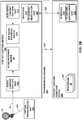
- FIG. 2 is a diagram illustrating a system 10 that may perform various aspects of the techniques described in this disclosure.
- the system 10 includes a content creator device 12 and a content consumer device 14. While described in the context of the content creator device 12 and the content consumer device 14, the techniques may be implemented in any context in which SHCs (which may also be referred to as HOA coefficients) or any other hierarchical representation of a soundfield are encoded to form a bitstream representative of the audio data.
- the content creator device 12 may represent any form of computing device capable of implementing the techniques described in this disclosure, including a handset (or cellular phone), a tablet computer, a smart phone, or a desktop computer to provide a few examples.
- the content consumer device 14 may represent any form of computing device capable of implementing the techniques described in this disclosure, including a handset (or cellular phone), a tablet computer, a smart phone, a set-top box, or a desktop computer to provide a few examples.
- the content creator device 12 may be operated by a movie studio or other entity that may generate multi-channel audio content for consumption by operators of content consumer devices, such as the content consumer device 14.
- the content creator device 12 may be operated by an individual user who would like to compress HOA coefficients 11.
- the content creator generates audio content in conjunction with video content.
- the content consumer device 14 may be operated by an individual.
- the content consumer device 14 may include an audio playback system 16, which may refer to any form of audio playback system capable of rendering SHC for play back as multi-channel audio content.
- the content creator device 12 includes a content capture device 300 and a content capture assistant device 302.
- the content capture device 300 may be configured to interface or otherwise communicate with a microphone 5.
- the microphone 5 may represent an Eigenmike® or other type of 3D audio microphone capable of capturing and representing the soundfield as HOA coefficients 11.
- the content capture device 300 may, in some examples, include an integrated microphone 5 that is integrated into the housing of the content capture device 300.
- the content capture device 300 may interface wirelessly or via a wired connection with the microphone 5.
- Various combinations of the content capture device and the microphone are described in more detail below.
- the content capture device 300 may include a camera, a ruggedized camera (which may include a protective case and components suitable for live recording during sports and other rugged activities), a cellular phone, a so-called “smart phone,” a tablet computer, a desktop computer, a workstation, or any other device capable of interfacing with the microphone 5 to capture the HOA coefficients 11 representative of the soundfield.
- the content capture device 300 may also be configured to interface or otherwise communicate with the content capture assistant device 302.
- the content capture assistant device 302 may include a cellular phone, a so-called "smart phone,” a tablet computer, a desktop computer, a workstation, or any other device capable of interfacing with the content capture device 300.
- the content capture device 300 may, in some examples, be configured to wirelessly communicate with the content capture assistant device 302.
- the content capture device 300 may communicate, via one or both of a wireless connection or a wired connection, communicate with the content capture assistant device 302.
- the content capture device 300 may provide content in various forms of content 301.
- the content 301 may include one or more of video data, text data, image data, and audio data.
- the video data may be in an uncompressed form or a compressed form.
- the content includes image data
- the image data may be in an uncompressed form or a compressed form.
- the audio data may be in an uncompressed form or a compressed form.
- the content capture assistant device 302 may represent a device configured to interface with the content capture device 300 to assist in capturing the content 301.
- the content capture assistant device 302 may, in some examples, execute an application (which may be referred to as an "app") configured to allow an operator of the content capture assistant device 302 to control the operation of the content capture device 300.
- the application may allow the operator to configure various settings of the content capture device 300, such as video recording settings, text settings, image capture settings, and audio recording settings.
- the application may also allow the operator to initiate capture of the content 301, stop capture of the content 301 or both initiate and stop the capture of the content 301.
- the content capture assistant device 302 may also assist in various ways with the processing of the content 301.
- the content capture device 300 may leverage various aspects of the content capture assistant device 302 (in terms of hardware or software capabilities of the content capture assistant device 302).
- the content capture assistant device 302 may include dedicated hardware configured to (or specialized software that when executed causes one or more processors to) perform psychoacoustic audio encoding (such as a unified speech and audio coder denoted as "USAC" set forth by the Motion Picture Experts Group (MPEG)).
- the content capture device 300 may not include the psychoacoustic audio encoder dedicated hardware or specialized software and instead provide audio aspects of the content 301 in a non-psychoacoustic-audio-coded form.
- the content capture assistant device 302 may assist in the capture of content 301 by, at least in part, performing psychoacoustic audio encoding with respect to the audio aspects of the content 301.
- the content capture assistant device 302 may also assist in content capture by generating one or more bitstreams 21 based, at least in part, on the content 301.
- the bitstream 21 may represent a compressed version of the HOA coefficients 11 and any other different types of the content 301 (such as a compressed version of captured video data, image data, or text data).
- the content capture assistant device 302 may generate the bitstream 21 for transmission, as one example, across a transmission channel, which may be a wired or wireless channel, a data storage device, or the like.
- the bitstream 21 may represent an encoded version of the HOA coefficients 11 and may include a primary bitstream and another side bitstream, which may be referred to as side channel information.
- the content creator device 12 may output the bitstream 21 to an intermediate device positioned between the content creator device 12 and the content consumer device 14.
- the intermediate device may store the bitstream 21 for later delivery to the content consumer device 14, which may request the bitstream.
- the intermediate device may comprise a file server, a web server, a desktop computer, a laptop computer, a tablet computer, a mobile phone, a smart phone, or any other device capable of storing the bitstream 21 for later retrieval by an audio decoder.
- the intermediate device may reside in a content delivery network capable of streaming the bitstream 21 (and possibly in conjunction with transmitting a corresponding video data bitstream) to subscribers, such as the content consumer device 14, requesting the bitstream 21.
- the content creator device 12 may store the bitstream 21 to a storage medium, such as a compact disc, a digital video disc, a high definition video disc or other storage media, most of which are capable of being read by a computer and therefore may be referred to as computer-readable storage media or non-transitory computer-readable storage media.
- a storage medium such as a compact disc, a digital video disc, a high definition video disc or other storage media, most of which are capable of being read by a computer and therefore may be referred to as computer-readable storage media or non-transitory computer-readable storage media.
- the transmission channel may refer to the channels by which content stored to the mediums are transmitted (and may include retail stores and other store-based delivery mechanism). In any event, the techniques of this disclosure should not therefore be limited in this respect to the example of FIG. 2 .
- the content consumer device 14 includes the audio playback system 16.
- the audio playback system 16 may represent any audio playback system capable of playing back multi-channel audio data.
- the audio playback system 16 may include a number of different renderers 22.
- the renderers 22 may each provide for a different form of rendering, where the different forms of rendering may include one or more of the various ways of performing vector-base amplitude panning (VBAP), and/or one or more of the various ways of performing soundfield synthesis.
- VBAP vector-base amplitude panning
- a and/or B means "A or B", or both "A and B".
- the audio playback system 16 may further include an audio decoding device 24.
- the audio decoding device 24 may represent a device configured to decode HOA coefficients 15 from the bitstream 21, where the HOA coefficients 15 may be similar to the HOA coefficients 11 but differ due to lossy operations (e.g., quantization) and/or transmission via the transmission channel.
- the audio playback system 16 may, after decoding the bitstream 21 to obtain the HOA coefficients 15 and render the HOA coefficients 15 to output loudspeaker feeds 25.
- the loudspeaker feeds 25 may drive one or more loudspeakers (which are not shown in the example of FIG. 2 for ease of illustration purposes).
- the audio playback system 16 may obtain loudspeaker information 13 indicative of a number of loudspeakers and/or a spatial geometry of the loudspeakers. In some instances, the audio playback system 16 may obtain the loudspeaker information 13 using a reference microphone and driving the loudspeakers in such a manner as to dynamically determine the loudspeaker information 13. In other instances or in conjunction with the dynamic determination of the loudspeaker information 13, the audio playback system 16 may prompt a user to interface with the audio playback system 16 and input the loudspeaker information 13.
- the audio playback system 16 may then select one of the audio renderers 22 based on the loudspeaker information 13. In some instances, the audio playback system 16 may, when none of the audio renderers 22 are within some threshold similarity measure (in terms of the loudspeaker geometry) to the loudspeaker geometry specified in the loudspeaker information 13, generate the one of audio renderers 22 based on the loudspeaker information 13. The audio playback system 16 may, in some instances, generate one of the audio renderers 22 based on the loudspeaker information 13 without first attempting to select an existing one of the audio renderers 22. One or more speakers may then playback the rendered loudspeaker feeds 25.
- some threshold similarity measure in terms of the loudspeaker geometry
- FIGS. 3A and 3B are block diagrams illustrating example implementations of the content capture device 300 and the content capture assistant device 302 in more detail.
- the example of FIG. 3A is generally directed to post-transcoding stabilization techniques of this disclosure.
- the content capture device 300 includes an audio content capture unit 310, an audio encoding device 20, a non-audio content capture unit 312, a non-audio encoding device 314, and interface unit 316 ("interface 316").
- the content capture device 300 also includes a stabilization unit 320.
- the audio content capture unit 310 may represent a unit configured to interface with the microphone 5 and supply audio data received from the microphone 5 to the stabilization unit 320.
- the audio content capture unit 310 may provide the captured HOA coefficients 11 to the stabilization unit 320.
- the microphone 5 is described above as capturing the HOA coefficients 11 above, it will be appreciated that, in various implementations, other components of the content capture device (e.g., the audio content capture unit 310) may generate the HOA coefficients 11 using audio data provided by the microphone 5.
- the stabilization unit 320 may transcode the outputs of the microphone 5 into HOA coefficients using position information for each individual microphone included in the microphone array of the microphone 5.
- the stabilization unit 320 may implement techniques of this disclosure to adjust the HOA coefficients 11 to compensate for particular motion information related to microphone 5. More specifically, the stabilization unit 320 may stabilize audio objects of a soundfield to mitigate or, in some cases, remove the effects caused by microphone jitter or other such movements associated with the microphone 5. In the example of FIG. 3A , the stabilization unit 320 may remediate jitter-indicating movements of the microphone 5 using data in the HOA domain (namely, the HOA coefficients 11).
- the stabilization unit 320 may receive the movement information for the microphone 5 from a device configured to sense motion information in multiple degrees of freedom, for example, three dimensions (3D) or six degrees of freedom, such as an accelerometer or compass that helps to track movement. In turn, the stabilization unit 320 may apply the 3D motion information to perform the motion stabilization techniques of this disclosure.
- the microphone 5 may include a built-in accelerometer (e.g., positioned at the center of the spherical array of the individual microphones), or may be coupled to an external accelerometer (e.g., an accelerometer affixed to other components of the microphone 5).
- the accelerometer may be included in the stem or handle of the microphone 5.
- the accelerometer may be positioned at any location that rotates along the same plane or along a substantially similar plane to the array of the microphone 5. More specifically, the stabilization unit 320 may perform the motion stabilization by applying inverse rotation to the HOA coefficients 11.
- Stabilizing the soundfield by compensating for movements may be more computationally efficient when implemented in the HOA domain (e.g., with respect to the HOA coefficients 11), as is the case in the implementation of FIG. 3A .
- the solution illustrated in FIG. 3A may be more feasible than other alternatives.
- the stabilization unit 320 may compensate movements (e.g., jitter) in the 3D soundfield captured by the microphone 5 without requiring the introduction of structural constraints and additions to the microphone 5 or the content capture device 300.
- the stabilization unit 320 may compensate movements, such as jitter, without potentially impeding the usability of the content capture device 300 and/or the microphone 5 with respect to capturing user-generated content and/or first person accounts.
- the stabilization unit 320 may analyze the motion information associated with the microphone 5, and rotate the soundfield in an inverse manner to the recorded motion information. In some examples, the stabilization unit 320 may only compensate (or inversely rotate) certain movements of the microphone 5. For instance, the stabilization unit 320 may compensate only quick movements, jitters, or high-frequency movements, all of which are described as "micromovements" above. More specifically, in this example, the stabilization unit 320 may retain other (e.g., smoother, or more gradual) motion information recorded by the accelerometer, thereby maintaining the integrity of 3D audio generation.
- the stabilization unit 320 may implement the motion stabilization techniques of this disclosure by applying an effects matrix to the HOA coefficients 11.
- the stabilization unit 320 may generate the effects matrix using the motion information recorded for the microphone 5 by the accelerometer. More specifically, the stabilization unit 320 may generate the effects matrix such that the application of the effects matrix to a soundfield results in an inverse rotation of the soundfield, as compared to the motion information recorded by the accelerometer for the microphone 5.
- the stabilization unit 320 may add a mixing and/or a weighting to the HOA coefficients 11 generated by the audio content capture unit 310.
- the HOA coefficients 11 received by the stabilization unit 320 may represent "uncompensated" HOA coefficients.
- the stabilization unit 320 may generate the motion-compensated HOA coefficients 15. Further details of the effects matrix and the motion compensation processes of this disclosure are described below with respect to FIGS. 4A-4D .
- the audio encoding device 20 may represent a unit configured to code the HOA coefficients 11 so as to reduce the size (in bits) of the HOA coefficients 11.
- the audio encoding device 20 may generate the bitstream 21, which is then passed to the content capture assistant device 302 for purposes of retransmission or storage.
- the audio encoding device 20 may generate the bitstream 21 to conform to known audio standards, such as the ISO/IEC JTC1/SC29/WG11 emerging standard entitled " RM1-HOA Working Draft Text," dated January 2014, and presented in San Jose, USA with document number ISO/IEC JTC1/SC29/WG11 MPEG2014/M31827.
- the non-audio content capture unit 312 may represent a unit configured to capture all non-audio content, such as video data, image data or text data. It is assumed for purposes of illustration that the non-audio content capture unit 312 may capture non-audio content in the form of video data.
- the non-audio encoding device 314 may represent a unit configured to encode the video data.
- the non-audio encoding device 314 may generate a bitstream that conforms to a video coding standard.
- An example video coding standard is the High-Efficiency Video Coding (HEVC) standard, which was recentlv finalized by the Joint Collaboration Team on Video Coding (JCT-VC) of ITU-T Video Coding Experts Group (VCEG) and ISO/IEC Motion Picture Experts Group (MPEG).
- HEVC High-Efficiency Video Coding
- JCT-VC Joint Collaboration Team on Video Coding
- VCEG ITU-T Video Coding Experts Group
- MPEG ISO/IEC Motion Picture Experts Group
- the non-audio encoding device 314 may generate a bitstream 21 representative of a compressed version of the video data.
- the interface unit 316 represents a unit configured to interface with another device.
- the interface unit 316 may interface with the other device via a network, such as a wireless local area network (WLAN), a peer-to-peer network or a personal area network (PAN).
- WLAN wireless local area network
- PAN personal area network
- An example of a WLAN is an IEEE 802.11g WLAN that conforms to the IEEE 802.11g wireless standard.
- An example of a PAN is a PAN that conforms to the BluetoothTM set of specifications.
- the interface unit 316 may, in some examples, interface with the other device via a dedicated connection (e.g., a wire).
- each sample of HOA coefficients 11 includes (4+1) 2 or 25 coefficients.
- Each of the coefficients is a 32-bit number.
- Each sample of the HOA coefficients 11 is therefore approximately 25 x 32 or 800 bits.
- the content capture device 300 may invoke the interface 316 to interface via the transmission channel 321 with the content capture assistant device 302. Whether via PAN or WLAN, the transmission channel 321 may provide insufficient bandwidth to accommodate raw audio data in the form of uncompressed HOA coefficients 11, especially when the content capture device 300 is also attempting to provide the video data via the same transmission channel 321.
- a wireless transmission channel which may represent a PAN or WLAN transmission channel
- the techniques may also be utilized in wired settings. In wired settings, certain other limitations may arise, such as limits in data processing, caching and storage speeds. Moreover, storage sizes may limit how much data can be stored. As such, the techniques should not be limited to the examples of wireless transmission channels, but may also apply to wired settings. Moreover, the data processing, caching, storage speeds and storage size limitations may also arise in both wired and wireless settings. Accordingly, the techniques may apply in any combination of these settings with any combination of the limitations.
- the content capture device 300 may first encode the HOA coefficients 11 and any accompanying non-audio data, such as the video data. To encode the HOA coefficients 11, the content capture device 300 may invoke the audio encoding device 20. The audio encoding device 20 may encode the HOA coefficients 11 to obtain the bitstream 21, providing the bitstream 21 as part of the content 301.
- the interface 316 may, when forming the transmission channel 321, invoke the transmission (TX) channel negotiation unit 317.
- the TX channel negotiation unit 317 may negotiate with the corresponding TX channel negotiation unit 317 of the interface 316 included within the content capture assistant device 302.
- the TX channel negotiation unit 317 of the content capture device 300 and the corresponding TX channel negotiation unit 317' of the content capture assistant device 302 may then negotiate establishment of the transmission channel 321, selecting appropriate channels and configuring these channels to allow for data communications between interface 316 of the content capture device 300 and the corresponding interface 316' of the content capture assistant device 302.
- the TX channel negotiation unit 317 of the content capture device 300 may request information regarding various aspects of the content capture assistant device 302.
- the information may comprise information indicative of a storage capacity available at the content capture assistant device 302 for the storage of the content 301.
- the TX channel negotiation unit 317 of the content capture assistant device 302 may provide the information indicative of the storage capacity to the TX channel negotiation unit 317 of the content capture device 300.
- FIG. 3B illustrates an example implementation that is generally directed to pre-transcoding stabilization techniques of this disclosure.
- the implementation of FIG. 3B is directed to motion compensation operation(s) on audio data at a pre-transcoding stage, i.e. audio data that is not in the HOA domain.
- the virtual repositioning unit 330 may communicate the virtual repositioning data 331 to the microphone 5 to compensate movements, such as movements indicative of jitter.
- microphone 5 may apply the virtual repositioning data 331 to adjust the spatial information for audio objects captured by the individual microphones of the microphone 5, and propagate the virtual repositioning for future audio captures. Further details of the pre-transcoding stabilization techniques of FIG. 3B are described below with respect to FIG. 5 .
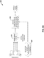
- FIG. 4A is a flowchart illustrating exemplary operation of an audio encoding device in performing the coding techniques described in this disclosure.
- the process 200 may be performed by a variety of devices, for ease of discussion purposes only, the process 200 is described below as being performed by one or more components of the audio encoding device 20 of FIG. 3A .
- the stabilization unit 320 (and/or one or more components thereof, working individually or in various combinations) may implement the process 200 of FIG. 4A to stabilize audio objects of a soundfield to mitigate or, in some cases, remove the effects caused by microphone jitter or other such movements.
- FIG. 4A illustrates an implementation in which the stabilization unit 320 of Figure 3A remediates movement issues in the HOA domain. As shown in the particular example of FIG.
- the stabilization unit 320 may transcode the microphone outputs into HOA coefficients using the actual positions of each individual microphone of 3D audio-enabled microphone array M 1 through M n (210). For instance, the actual position information for each individual microphone may reflect the movements (including jitter and/or so-called "micromovements") caused by the movement of the microphone array.
- the stabilization unit 320 may receive motion information for the microphones M 1 through M n from a device configured to sense motion information in 3D, such as an accelerometer or compass that helps to track movement (220). In turn, the stabilization unit 320 may use the received motion information to derive or otherwise determine movement information for each of the individual microphones microphones M 1 through M n . The stabilization unit 320 may apply the 3D motion information to perform the motion stabilization techniques of this disclosure (230).
- the microphone may include a built-in accelerometer (e.g., positioned at the center of the spherical array of individual microphones M 1 through M n ), or may be coupled to an external accelerometer (e.g., an accelerometer affixed to other components of a camera/microphone setup).
- the accelerometer may be included in the stem or handle of the microphone.
- the stabilization unit 320 may perform the motion stabilization by applying inverse rotation to an HOA domain-representation of the 3D soundfield captured by the array of individual microphones M 1 through M n .
- the accelerometer may be positioned at any location that rotates along the same plane or along a substantially similar plane to the array of individual microphones M 1 through M n .
- the stabilization unit 320 may derive the motion information for the microphone array even if the accelerometer does not rotate along the same or a substantially similar plane as the microphone array. In this manner, the stabilization unit 320 may implement techniques of this disclosure to leverage data provided by the accelerometer in a variety of ways to determine the motion information of the microphone array, and in turn obtain movement information of each of the individual microphones M 1 through M n .
- Stabilizing the soundfield by compensating movements may be more computationally efficient when implemented in the HOA domain, as is the case in the example of FIG. 4A .
- the solution of the process 200 may be more feasible than other alternatives.
- the stabilization unit 320 may compensate movements in the soundfield without requiring the introduction of structural constraints and additions to a camera and/or microphone system.
- the stabilization unit 320 may compensate movements without potentially impeding the usability of the camera and/or microphone systems with respect to capturing user-generated content and/or first person accounts.
- the stabilization unit 320 may analyze the received (220) motion information, and rotate the soundfield in an inverse manner to the captured motion (230). In some examples, the stabilization unit 320 may only compensate (or inversely rotate) certain movements received at the step 220. For instance, the stabilization unit 320 may compensate only quick movements, jitters, or high-frequency movements, all of which are described as "micromovements" above. More specifically, in this example, the audio encoding device 20 may retain other (e.g., smoother, or more gradual) motion information, thereby maintaining the integrity of 3D audio generation.
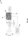
- FIG. 4B is a flowchart illustrating an alternative representation of the process 200 of FIG. 4A .
- the motion stabilization is illustrated by way of an effects matrix 240.
- the audio encoding device 20 may generate the effects matrix 240 using the motion information received for the microphones M 1 through M n at the step 220. More specifically, the stabilization unit 320 may generate the effects matrix 240 such that the application of the effects matrix 240 to a soundfield results in an inverse rotation of the soundfield, as compared to the motion information received at the step 220.
- the effects matrix 240 includes a zero region 242, which is graphically distinguished from a significant region 244 in FIG. 4B .
- the zero region may represent matrix entries or cells that do not indicate any rotation to the uncompensated HOA coefficients to which the effects matrix 240 is applied.
- the significant region 244 may represent matrix entries or cells that have a certain "weight" associated, and thus, represent some level of rotation to rotate the uncompensated HOA coefficients generated at the step 210.
- the stabilization unit 320 may add a mixing and/or a weighting to the uncompensated HOA coefficients generated at the step 210.
- the stabilization unit 320 may perform the motion stabilization techniques of this disclosure to inversely rotate only a minority of the uncompensated HOA coefficients transcoded at the step 210. As illustrated in FIG. 4B , the stabilization unit 320 may perform motion compensation according to this disclosure in a computationally efficient manner, by targeting specific movements (e.g., micromovements that indicate jitter) received at the step 220, and compensating only the targeted movements, by applying the effects matrix 240.
- specific movements e.g., micromovements that indicate jitter
- FIG. 4C is a conceptual diagram illustrating various angles (i.e., rotations) that the stabilization unit 320 may use in measuring 3D movement of audio objects of a soundfield.
- the effects matrix 240 is represented by the expression R( ⁇ , ⁇ , ⁇ ).
- the audio encoding device 20 may apply one or more filters, such as a lowpass filter, a median filter, or a Kalman filter.
- the rotation matrix is computed in the spatial domain and converted into the HOA domain via a discrete spherical harmonic transform ("DSHT").
- DSHT discrete spherical harmonic transform
- the rotation matrix M rot in the HOA domain is computed based on the rotation kernel R ( ⁇ , ⁇ , ⁇ ) and the spherical harmonics up to the HOA order N for the directions ⁇ and R ⁇ ⁇ .
- FIG. 4D is a conceptual diagram illustrating a refinement that the stabilization unit 320 may implement with respect to the process 200 for motion stabilization of audio objects in the HOA domain.
- the stabilization unit 320 may calculate and apply separate instances of the effects matrix 240 to every audio sample, or frame, thereby compensating the audio objects of each sample to remediate movement-induced changes to the corresponding spatial information.
- the stabilization unit 320 may conserve computing resources by deriving and applying separate instances of the effects matrix 240 to a sample at a given interval, e.g., every 10 samples, every 12, or so on.
- the interval of samples determined by the stabilization unit 320 is referred to as a "block" of samples herein.
- FIG. 4D illustrates four such blocks, namely, the audio sample blocks 250A-250D.
- the audio encoding device may apply techniques of this disclosure to interpolate the separate instances of the effects matrix 240.
- the stabilization unit 320 may "smooth out" the transitions within each of the audio sample blocks 250A-250D by applying the corresponding interpolation functions 260A-260D to the previous instance of the effects matrix 240.
- the stabilization unit 320 may apply techniques of this disclosure to mitigate precision loss, while improving coding efficiency. More specifically, the stabilization unit 320 may exploit the sparseness of the effects matrix 240 (e.g., in terms of significant weight values as opposed to the more common zero entries) to annlv the effects matrix 240 at multi-sample intervals, and interpolating the effects matrix 240 through the intervals.
- the interpolation-based implementation of FIG. 4D may represent a more efficient and computationally less-taxing solution than real-time computation and application of the effects matrix 240 for each sample of the transcoded audio input.
- the post-transcoding motion compensation techniques described with respect to FIGS. 4A -4D are customizable. Other customizations that are possible with respect to the post-transcoding motion compensation techniques include applying the motion compensation to target only select segments of captured audio data, setting thresholds to determine whether a movement qualifies as a micromovement to be compensated, and so on.
- the post-transcoding motion compensation solution of FIGS 4A-4D represent a customizable solution that the audio encoding device 20 may implement to compensate micromovements, based on device characteristics, sound characteristics, user input or settings, or various other parameters that are specific to a particular scenario.
- FIG. 5 is a flowchart illustrating exemplary operation of an audio decoding device in performing the coding techniques described in this disclosure.
- FIG. 5 illustrates an example process 270 by which the virtual repositioning unit 330 (and/or one or more components thereof, functioning either individually or in any combination) may stabilize audio objects of a soundfield by implementing motion compensation, in accordance with various aspects of this disclosure.
- the virtual repositioning unit 330 may perform the motion compensation operation(s) on audio data at a pre-transcoding stage, i.e. audio data that is not in the HOA domain.
- the virtual repositioning unit 330 may perform a virtual repositioning of one or more of the individual microphones M 1 through M n (280) to compensate movements. More specifically, the inputs to the step 280 include motion information of the microphone array, as determined from a 3D motion sensor (e.g., accelerometer) at the step 210, and the actual positions of the individual microphones M 1 through M n . In turn, the virtual repositioning unit 330 may combine the motion information received at the step 210 with the actual microphone positions to derive the virtual repositioning information at the step 280. The audio encoding device may apply the virtual repositioning at the step 280 to adjust the spatial information for audio objects captured by the individual microphones M 1 through M n , and propagate the virtual repositioning for future audio captures.
- a 3D motion sensor e.g., accelerometer
- the process 270 illustrated in FIG. 5 represents a low-complexity, and thus, computationally less expensive implementation as compared to the post-transcoding compensation techniques described with respect to FIGS. 4A-4D .
- the virtual repositioning unit 330 may mitigate or potentially eliminate the effects of microphone jitter, while conserving computing resources and energy consumption.
- the process 270 may illustrate a motion compensation process that is viable for low-battery scenarios, as well as scenarios in which the audio encoding device has relatively less computing resources available (e.g., via a smartphone or a tablet computer).
- the conversion (or transcoding) from the microphone signals x L of a spherical microphone array into the HOA domain may be performed via a discrete spherical transform DSHT in combination with subsequent signal processing based on geometric properties of the array.
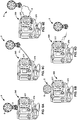
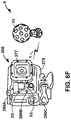
- FIGS. 6A-6F are diagrams illustrating different combinations of the content capture device 300 and the microphone 5.
- the content capture device 300 (shown as a ruggedized camera for purposes of illustrations) may represent a camera system having a housing 375 in which an image capture system 377, including a lens, is configured to capture one or both of video data and image data.
- the housing 375 may be adapted to integrate the entire microphone 5, including a stand 3 of the microphone 5.
- the microphone 5 includes the stand 3 and a microphone array 6.
- the stand 3 may be affixed to the housing 375 and the microphone array 6.
- the microphone 5 does not include the stand 3, but is still integrated with the content capture device 300. In other words, the microphone 5 only includes the microphone array 6, which is affixed to the housing 375.
- the microphone 5 communicates with the content capture device 300 via a wire 4
- a processor (not shown) may be configured to obtain the HOA coefficients 11 via the wire 4.
- the microphone 5 is in wireless communication with the content capture device 300 via a PAN 1 and a WLAN 2 respectively.
- the processor may be configured, in the examples of FIGS. 6D and 6E , to obtain the HOA coefficients 11 wirelessly (e.g., via the PAN 1 and the WLAN 2 respectively).
- the content capture device 300 also includes integrated microphones 390A-390C.
- the 3D audio microphone 5 includes a microphone array, wherein each microphone of the microphone array is approximately a distance D1 from an adjacent microphone. Each microphone of the microphone array is also positioned equidistantly around a semi-sphere or, alternative, around a sphere.
- the integrated microphones of 390A-390C may be positioned a distance D2 from an adjacent microphone. The distance D2 may be larger than the distance D1.
- the content capture device 300 may include the integrated microphones 390A-390C to augment the HOA audio data captured by the microphone 5.
- the larger microphone separate (as represented by distance D2) of the integrated microphones 390A-390C may facilitate capture of lower frequencies. Because the distance D1 of the microphones of the microphone array is small, the microphone 5 may not be able to adequately capture lower frequencies.
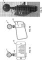
- FIGS. 7A-7E are diagrams illustrating different examples of a content capture device in the form of a smart phone that utilize a three-dimensional microphone secured to the content capture device in accordance with the techniques described in this disclosure.
- the content capture device 300 provides a platform to which a securing device 395 is affixed.
- the securing device 395 may include a clamp.
- the clamp may ratchet down via a tension ratcheting mechanism so as to accommodate different sizes and form factors of a potential content capture device 300 used with the microphone 5.
- the securing device 395 may include a number of microphone attachment points.
- the microphone attachment points may comprise female screw attachment points that accept common screw size and threading for cameras or other types of audio/visual equipment.
- the microphone attachment points may be located on the top of the clamp (where the top refers to the top of the clamp when used while the content capture device 300 is in held in a landscape orientation).
- the microphone attachment points may also be located on the rear of the clamp as shown in FIG. 7B by a microphone attachment point 397.
- FIGS. 7C-7E provide further side, back and front snapshots of the securing device 395.
- FIGS. 8A and 8B are diagrams illustrating different examples of the microphone 5.
- a 32 microphone array microphone developed by Qualcomm Technologies Inc.
- the microphone 5 of FIG. 8A includes, as one example, a USB wired connection.
- the example shown in FIG. 8B is an alternative microphone to the Qualcomm 32 microphone device, which is referred to as an EigenmikeTM.
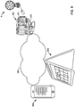
- FIG. 9 is a conceptual diagram illustrating an example content capture device 300 in communication with one or more example content capture assistant devices 302.
- the content capture assistant devices 302 may communicate with the content capture device 300 via a wireless local area network 380.
- the content capture assistant devices 302 may communicate with the content capture device 300 via a personal area network, a cellular network or other wireless forms of communication.
- the content capture assistant devices 302 may communicate with the content capture device 300 via a wired connection.
- the content capture device 300 may communicate with the microphone 5 via any form of communication, such as those described above with respect to the examples of FIGS. 4A-4D .
- this disclosure is directed to a method of motion compensation, the method including adjusting one or more higher-order ambisonics (HOA) representations of a three-dimensional (3D) soundfield to compensate one or more movements associated with a capture of one or more audio objects of the 3D soundfield.
- HOA ambisonics
- adjusting the one or more HOA representations includes obtaining an effects matrix associated with the one or more movements.
- the effects matrix represents an inverse rotation operation with respect to the one or more movements.
- adjusting the one or more HOA representations includes applying the effects matrix to the one or more HOA representations to obtain a motion compensated 3D soundfield.
- obtaining the effects matrix includes obtaining rotational information associated with the one or more movements and calculating the effects matrix at least in part by calculating an inverse of the rotational information.
- the effects matrix comprises a set of zero entries and a set of significant entries. According to one such example, the set of zero entries includes a greater number of entries than the set of significant entries.
- adjusting the one or more HOA representations comprises adjusting the one or more HOA representations for each audio sample of audio data.
- adjusting the one or more HOA representations comprises adjusting the one or more HOA representations for a subset of the audio samples, such that any pair of audio samples of the subset represents an interval of the plurality of the audio samples.
- the interval comprises one of a ten-sample interval or a twelve-sample interval.
- the method may further include interpolating the effects matrix with respect to each interval, to obtain one or more interpolated effects matrices. In one such example, the method may further include applying each interpolated effects matrix to a corresponding sample included in a corresponding interval.
- the method may further include obtaining data describing the movements from a motion sensing device.
- the motion sensing device comprises one or more of an accelerometer or a compass.
- the motion sensor is coupled to a microphone array that is configured to capture the audio data.
- the motion sensing device forms a part of the microphone array.
- the method may further include differentiating one or more micromovements from one or more gradual movements associated with the one or more audio objects of the 3D soundfield. In one such example, differentiating the micromovements from the gradual movements is based on a threshold value associated with one or more of a distance, a frequency, or an angle sharpness describing motion information associated with the capture.
- the method may further include obtaining one or more of a yaw angle, a pitch angle, or a roll angle associated with the movements.
- adjusting the one or more HOA representations includes altering spatial information associated with the one or more HOA representations.
- a device is configured to compensate motion, and the device may include a memory configured to store higher-order ambisonic (HOA) audio data, and one or more processors configured to perform any of the methods described above, or any combination of the described methods.
- HOA ambisonic
- a device is configured to compensate motion, and the device may include means for storing higher-order ambisonic (HOA) audio data, and means for performing any of the methods described above, or any combination of the described methods.
- HOA higher-order ambisonic
- a computer-readable storage medium may be encoded with instructions that, when executed, perform any of the methods described above, or any combination of the described methods.
- this disclosure is directed to a method of motion compensation.
- the method may include adjusting one or more higher order ambisonics (HOA) representations of a 3D soundfield to compensate one or more movements associated with a microphone array configured to capture one or more audio objects of the 3D soundfield.
- HOA ambisonics
- the method includes adjusting the virtual positioning information comprises adjusting the virtual positioning information for a time-domain representation of the 3D soundfield.
- the time-domain representation of the 3D soundfield comprises a pre-transcoding representation of the 3D soundfield.
- the method may further include adjusting the virtual positioning information for all audio samples captured by the microphone array with respect to the 3D soundfield.
- adjusting the virtual positioning information comprises generating virtual re-positioning information based on the movements and actual positioning information associated with the microphone array.
- the method further includes obtaining data describing the movements from a motion sensing device.
- the motion sensing device comprises one or more of an accelerometer or a compass.
- a device is configured to compensate motion, and the device may include a memory configured to store higher-order ambisonic (HOA) audio data, and one or more processors configured to perform any of the methods described above, or any combination of the described methods.
- a device is configured to compensate motion, and the device may include means for storing higher-order ambisonic (HOA) audio data, and means for performing any of the methods described above, or any combination of the described methods.
- a computer-readable storage medium may be encoded with instructions that, when executed, perform any of the methods described above, or any combination of the described methods.
- this disclosure is directed to a camera system that includes a housing, an image capture system, including a lens, to capture one or both of video data and image data, and a three-dimensional (3D) microphone configured to capture higher-order ambisonic audio data, wherein the 3D microphone including a stand and a microphone array, and wherein the stand is affixed to the housing of the camera and the microphone array.
- the housing is configured to receive one or more motion sensing devices.
- the 3D microphone is configured to be coupled to one or more motion sensing devices.
- the one or more motion sensing devices comprise at least one of an accelerometer or a compass.
- the accelerometer is configured to obtain motion information associated with the 3D microphone.
- the compass is configured obtain motion information associated with the 3D microphone that includes information associated with one or more cardinal directions.
- this disclosure is directed to a camera system that includes a housing, an image capture system, including a lens, to capture one or both of video data and image data, and a three-dimensional (3D) microphone configured to capture higher-order ambisonic audio data, wherein the 3D microphone includes a microphone array affixed to the housing of the camera.
- the housing is configured to receive one or more motion sensing devices.
- the 3D microphone is configured to be coupled to one or more motion sensing devices.
- the one or more motion sensing devices comprise at least one of an accelerometer or a compass.
- the accelerometer is configured to obtain motion information associated with the 3D microphone.
- the compass is configured obtain motion information associated with the 3D microphone that includes information associated with one or more cardinal directions.
- this disclosure is directed to a camera system that includes a processor, an image capture system, including a lens, to capture one or both of video data and image data, and a three-dimensional (3D) microphone configured to capture higher-order ambisonic audio data, where the 3D microphone includes a wire communicatively coupling the 3D microphone to the processor, and where the processor is configured to obtain the higher-order ambisonic audio data via the wire.
- the housing is configured to receive one or more motion sensing devices.
- the 3D microphone is configured to be coupled to one or more motion sensing devices.
- the one or more motion sensing devices comprise at least one of an accelerometer or a compass.
- the accelerometer is configured to obtain motion information associated with the 3D microphone.
- the compass is configured obtain motion information associated with the 3D microphone that includes information associated with one or more cardinal directions.
- this disclosure is directed to a method of motion compensation.
- the method comprises receiving, by a device configured to compensate motion, motion information indicating one or more movements associated with a capture of one or more audio objects of a three-dimensional (3D) soundfield by a microphone array.
- the method further includes adjusting, by the device configured to compensate motion, virtual positioning information associated with one or more microphones of a microphone array to compensate the one or more movements associated with the capture of the one or more audio objects of the 3D soundfield by the microphone array.
- the method may further include generating, by the device configured to compensate motion, a motion-compensated bitstream based on the adjusted virtual positioning information.
- adjusting the virtual positioning information comprises adjusting, by the device configured to compensate motion, one or more higher-order ambisonics (HOA) representations of the 3D soundfield.
- adjusting the one or more HOA representations comprises altering, by the device configured to compensate motion, spatial information associated with the one or more HOA representations.
- adjusting the one or more HOA representations comprises obtaining, by the device configured to compensate motion, an effects matrix associated with the one or more movements.
- the effects matrix represents an inverse rotation operation with respect to the one or more movements.
- adjusting the one or more HOA representations comprises applying, by the device configured to compensate motion, the effects matrix to the one or more HOA representations to obtain a motion compensated 3D soundfield.
- obtaining the effects matrix comprises obtaining, by the device configured to compensate motion, rotational information associated with the one or more movements, and calculating, by the device configured to compensate motion, the effects matrix at least in part by calculating an inverse of the rotational information.
- the effects matrix comprises a set of zero entries and a set of significant entries, and the set of zero entries includes a greater number of entries than the set of significant entries.
- adjusting the one or more HOA representations comprises adjusting, by the device configured to compensate motion, the one or more HOA representations for a subset of a plurality of audio samples associated with the 3D soundfield, such that any pair of audio samples of the subset represents an interval of the plurality of the audio samples.
- the interval comprises one of a ten-sample interval or a twelve-sample interval.
- the method further comprises interpolating, by the device configured to compensate motion, the effects matrix with respect to each interval, to obtain one or more interpolated effects matrices.
- the method further comprises applying, by the device configured to compensate motion, each interpolated effects matrix to a corresponding sample included in a corresponding interval.
- the method further comprises differentiating, by the device configured to compensate motion, one or more micromovements from one or more gradual movements associated with the one or more audio objects of the 3D soundfield.
- differentiating the micromovements from the gradual movements is based on a threshold value associated with one or more of a distance, a frequency, or an angle sharpness describing motion information associated with the capture.
- receiving the motion information indicating the one or more movements associated with the capture of the one or more audio objects of the 3D soundfield by the microphone array includes receiving, by the device configured to compensate motion, one or more of a yaw angle, a pitch angle, or a roll angle associated with the movements.
- adjusting the virtual positioning information to compensate the movements comprises compensating, by the device configured to compensate motion, rotation information based on the obtained one or more of the yaw angle, the pitch angle, or the roll angle.
- adjusting the virtual positioning information comprises adjusting, by the device configured to compensate motion, the virtual positioning information for a time-domain representation of the 3D soundfield.
- the time-domain representation of the 3D soundfield comprises a pre-transcoding representation of the 3D soundfield.
- the method further includes adjusting, by the device configured to compensate motion, the virtual positioning information for all audio samples captured by the microphone array with respect to the 3D soundfield.
- adjusting the virtual positioning information comprises generating, by the device configured to compensate motion, virtual re-positioning information based on the movements and actual positioning information associated with the microphone array.
- this disclosure is directed to a device configured to compensate motion.
- the device comprises a memory configured to store audio data associated with a three-dimensional (3D) soundfield and one or more processors.
- the one or more processors are configured to receive motion information indicating one or more movements associated with a capture of one or more audio objects of a three-dimensional (3D) soundfield by a microphone array, and to adjust virtual positioning information associated with one or more microphones of a microphone array to compensate one or more movements associated with a capture of one or more audio objects of the 3D soundfield by the microphone array.
- the one or more processors may also be configured to generate a motion-compensated bitstream based on the adjusted virtual positioning information.
- the one or more processors are further configured to obtain data describing the movements from a motion sensing device.
- the motion sensing device comprises one or more of an accelerometer or a compass.
- the one or more processors are configured to adjust one or more higher-order ambisonics (HOA) representations of the 3D soundfield.
- HOA ambisonics
- the one or more processors are configured to obtain an effects matrix associated with the one or more movements. In one such example, the effects matrix represents an inverse rotation operation with respect to the one or more movements.
- the one or more processors are configured to adjust the virtual positioning information by adjusting the virtual positioning information for a time-domain representation of the 3D soundfield.
- the time-domain representation of the 3D soundfield comprises a pre-transcoding representation of the 3D soundfield.
- the one or more processors are configured to adjust the virtual positioning information by generating virtual re-positioning information based on the movements and actual positioning information associated with the microphone array.
- this disclosure is directed to a device configured to compensate motion.
- the device comprises means for storing audio data associated with a three-dimensional (3D) soundfield, means for receiving motion information indicating one or more movements associated with a capture of one or more audio objects of the 3D soundfield by a microphone array, and means for adjusting virtual positioning information associated with one or more microphones of a microphone array to compensate the one or more movements associated with the capture of the one or more audio objects of the 3D soundfield by the microphone array.
- the device may also include means for generating a motion-compensated bitstream based on the adjusted virtual positioning information.
- the means for adjusting the virtual positioning information include means for adjusting one or more higher-order ambisonics (HOA) representations of the 3D soundfield.
- the means for adjusting the virtual positioning information include: means for obtaining rotational information associated with the one or more movements, means for calculating an inverse of the rotational information to obtain an effects matrix representing an inverse operation with respect to the rotational information, and means for applying the effects matrix to the one or more HOA representations to obtain a motion compensated 3D soundfield.
- the means for adjusting the virtual positioning information comprise means for adjusting the virtual positioning information for a time-domain representation of the 3D soundfield, the time-domain representation of the 3D soundfield comprising a pre-transcoding representation of the 3D soundfield.
- this disclosure is directed to a non-transitory computer-readable storage medium encoded with instructions.
- the instructions when executed, cause one or more processors of a computing device for compensating motion to receive motion information indicating one or more movements associated with a capture of one or more audio objects of the 3D soundfield by a microphone array, to adjust virtual positioning information associated with one or more microphones of a microphone array to compensate the one or more movements associated with the capture of one or more audio objects of the 3D soundfield by the microphone array, and to generate a motion-compensated bitstream based on the adjusted virtual positioning information.
- One example audio ecosystem may include audio content, movie studios, music studios, gaming audio studios, channel based audio content, coding engines, game audio stems, game audio coding / rendering engines, and delivery systems.
- the movie studios, the music studios, and the gaming audio studios may receive audio content.
- the audio content may represent the output of an acquisition.
- the movie studios may output channel based audio content (e.g., in 2.0, 5.1, and 7.1) such as by using a digital audio workstation (DAW).
- the music studios may output channel based audio content (e.g., in 2.0, and 5.1) such as by using a DAW.
- the coding engines may receive and encode the channel based audio content based one or more codecs (e.g., AAC, AC3, Dolby True HD, Dolby Digital Plus, and DTS Master Audio) for output by the delivery systems.
- codecs e.g., AAC, AC3, Dolby True HD, Dolby Digital Plus, and DTS Master Audio
- the gaming audio studios may output one or more game audio stems, such as by using a DAW.
- the game audio coding / rendering engines may code and or render the audio stems into channel based audio content for output by the delivery systems.
- Another example context in which the techniques may be performed comprises an audio ecosystem that may include broadcast recording audio objects, professional audio systems, consumer on-device capture, HOA audio format, on-device rendering, consumer audio, TV, and accessories, and car audio systems.
- the broadcast recording audio objects, the professional audio systems, and the consumer on-device capture may all code their output using HOA audio format.
- the audio content may be coded using the HOA audio format into a single representation that may be played back using the on-device rendering, the consumer audio, TV, and accessories, and the car audio systems.
- the single representation of the audio content may be played back at a generic audio playback system (i.e., as opposed to requiring a particular configuration such as 5.1, 7.1, etc.), such as audio playback system 16.
- the acquisition elements may include wired and/or wireless acquisition devices (e.g., Eigen microphones), on-device surround sound capture, and mobile devices (e.g., smartphones and tablets).
- wired and/or wireless acquisition devices may be coupled to mobile device via wired and/or wireless communication channel(s).
- the mobile device may be used to acquire a soundfield.
- the mobile device may acquire a soundfield via the wired and/or wireless acquisition devices and/or the on-device surround sound capture (e.g., a plurality of microphones integrated into the mobile device).
- the mobile device may then code the acquired soundfield into the HOA coefficients for playback by one or more of the playback elements.
- a user of the mobile device may record (acquire a soundfield of) a live event (e.g., a meeting, a conference, a play, a concert, etc.), and code the recording into HOA coefficients.
- a live event e.g., a meeting, a conference, a play, a concert, etc.
- the mobile device may also utilize one or more of the playback elements to playback the HOA coded soundfield. For instance, the mobile device may decode the HOA coded soundfield and output a signal to one or more of the playback elements that causes the one or more of the playback elements to recreate the soundfield.
- the mobile device may utilize the wireless and/or wireless communication channels to output the signal to one or more speakers (e.g., speaker arrays, sound bars, etc.).
- the mobile device may utilize docking solutions to output the signal to one or more docking stations and/or one or more docked speakers (e.g., sound systems in smart cars and/or homes).
- the mobile device may utilize headphone rendering to output the signal to a set of headphones, e.g., to create realistic binaural sound.
- a particular mobile device may both acquire a 3D soundfield and playback the same 3D soundfield at a later time.
- the mobile device may acquire a 3D soundfield, encode the 3D soundfield into HOA, and transmit the encoded 3D soundfield to one or more other devices (e.g., other mobile devices and/or other non-mobile devices) for playback.
- an audio ecosystem may include audio content, game studios, coded audio content, rendering engines, and delivery systems.
- the game studios may include one or more DAWs which may support editing of HOA signals.
- the one or more DAWs may include HOA plugins and/or tools which may be configured to operate with (e.g., work with) one or more game audio systems.
- the game studios may output new stem formats that support HOA.
- the game studios may output coded audio content to the rendering engines which may render a soundfield for playback by the delivery systems.
- the techniques may also be performed with respect to exemplary audio acquisition devices.
- the techniques may be performed with respect to an Eigen microphone which may include a plurality of microphones that are collectively configured to record a 3D soundfield.
- the plurality of microphones of Eigen microphone may be located on the surface of a substantially spherical ball with a radius of annroximately 4cm.
- the audio encoding device 20 may be integrated into the Eigen microphone so as to output a bitstream 21 directly from the microphone.
- Another exemplary audio acquisition context may include a production truck which may be configured to receive a signal from one or more microphones, such as one or more Eigen microphones.
- the production truck may also include an audio encoder, such as audio encoder 20.
- the mobile device may also, in some instances, include a plurality of microphones that are collectively configured to record a 3D soundfield.
- the plurality of microphone may have X, Y, Z diversity.
- the mobile device may include a microphone which may be rotated to provide X, Y, Z diversity with respect to one or more other microphones of the mobile device.
- the mobile device may also include an audio encoder, such as audio encoder 20.
- a ruggedized video capture device may further be configured to record a 3D soundfield.
- the ruggedized video capture device may be attached to a helmet of a user engaged in an activity.
- the ruggedized video capture device may be attached to a helmet of a user whitewater rafting.
- the ruggedized video capture device may capture a 3D soundfield that represents the action all around the user (e.g., water crashing behind the user, another rafter speaking in front of the user, etc).
- the techniques may also be performed with respect to an accessory enhanced mobile device, which may be configured to record a 3D soundfield.
- the mobile device may be similar to the mobile devices discussed above, with the addition of one or more accessories.
- an Eigen microphone may be attached to the above noted mobile device to form an accessory enhanced mobile device.
- the accessory enhanced mobile device may capture a higher quality version of the 3D soundfield than just using sound capture components integral to the accessory enhanced mobile device.
- Example audio playback devices that may perform various aspects of the techniques described in this disclosure are further discussed below.
- speakers and/or sound bars may be arranged in any arbitrary configuration while still playing back a 3D soundfield.
- headphone playback devices may be coupled to a decoder 24 via either a wired or a wireless connection.
- a single generic representation of a soundfield may be utilized to render the soundfield on any combination of the speakers, the sound bars, and the headphone playback devices.
- a number of different example audio playback environments may also be suitable for performing various aspects of the techniques described in this disclosure.
- a 5.1 speaker playback environment a 2.0 (e.g., stereo) speaker playback environment, a 9.1 speaker playback environment with full height front loudspeakers, a 22.2 speaker playback environment, a 16.0 speaker playback environment, an automotive speaker playback environment, and a mobile device with ear bud playback environment may be suitable environments for performing various aspects of the techniques described in this disclosure.
- a single generic representation of a soundfield may be utilized to render the soundfield on any of the foregoing playback environments.
- the techniques of this disclosure enable a rendered to render a soundfield from a generic representation for playback on the playback environments other than that described above. For instance, if design considerations prohibit proper placement of speakers according to a 7.1 speaker playback environment (e.g., if it is not possible to place a right surround speaker), the techniques of this disclosure enable a render to compensate with the other 6 speakers such that playback may be achieved on a 6.1 speaker playback environment.
- the 3D soundfield of the sports game may be acquired (e.g., one or more Eigen microphones may be placed in and/or around the baseball stadium), HOA coefficients corresponding to the 3D soundfield may be obtained and transmitted to a decoder, the decoder may reconstruct the 3D soundfield based on the HOA coefficients and output the reconstructed 3D soundfield to a renderer, the renderer may obtain an indication as to the type of playback environment (e.g., headphones), and render the reconstructed 3D soundfield into signals that cause the headphones to output a representation of the 3D soundfield of the sports game.
- the type of playback environment e.g., headphones
- the audio encoding device 20 may perform a method or otherwise comprise means to perform each step of the method for which the audio encoding device 20 is configured to perform
- the means may comprise one or more processors.
- the one or more processors may represent a special purpose processor configured by way of instructions stored to a non-transitory computer-readable storage medium.
- various aspects of the techniques in each of the sets of encoding examples may provide for a non-transitory computer-readable storage medium having stored thereon instructions that, when executed, cause the one or more processors to perform the method for which the audio encoding device 20 has been configured to perform.
- the functions described may be implemented in hardware, software, firmware, or any combination thereof. If implemented in software, the functions may be stored on or transmitted over as one or more instructions or code on a computer-readable medium and executed by a hardware-based processing unit.
- Computer-readable media may include computer-readable storage media, which corresponds to a tangible medium such as data storage media. Data storage media may be any available media that can be accessed by one or more computers or one or more processors to retrieve instructions, code and/or data structures for implementation of the techniques described in this disclosure.
- a computer program product may include a computer-readable medium.
- the audio decoding device 24 may perform a method or otherwise comprise means to perform each step of the method for which the audio decoding device 24 is configured to perform.
- the means may comprise one or more processors.
- the one or more processors may represent a special purpose processor configured by way of instructions stored to a non-transitory computer-readable storage medium.
- various aspects of the techniques in each of the sets of encoding examples may provide for a non-transitory computer-readable storage medium having stored thereon instructions that, when executed, cause the one or more processors to perform the method for which the audio decoding device 24 has been configured to perform.
- Such computer-readable storage media can comprise RAM, ROM, EEPROM, CD-ROM or other optical disk storage, magnetic disk storage, or other magnetic storage devices, flash memory, or any other medium that can be used to store desired program code in the form of instructions or data structures and that can be accessed by a computer.
- computer-readable storage media and data storage media do not include connections, carrier waves signals, or other transitory media, but are instead directed to non-transitory, tangible storage media.
- Disk and disc includes compact disc (CD), laser disc, optical disc, digital versatile disc (DVD), floppy disk and Blu-ray disc, where disks usually reproduce data magnetically, while discs reproduce data optically with lasers. Combinations of the above should also be included within the scope of computer-readable media.
- processors such as one or more digital signal processors (DSPs), general purpose microprocessors, application specific integrated circuits (ASICs), field programmable logic arrays (FPGAs), or other equivalent integrated or discrete logic circuitry.
- DSPs digital signal processors
- ASICs application specific integrated circuits
- FPGAs field programmable logic arrays
- processors may refer to any of the foregoing structure or any other structure suitable for implementation of the techniques described herein.
- the functionality described herein may be provided within dedicated hardware and/or software modules configured for encoding and decoding, or incorporated in a combined codec. Also, the techniques could be fully implemented in one or more circuits or logic elements.
- the techniques of this disclosure may be implemented in a wide variety of devices or apparatuses, including a wireless handset, an integrated circuit (IC) or a set of ICs (e.g., a chip set).
- IC integrated circuit
- a set of ICs e.g., a chip set.
- Various components, modules, or units are described in this disclosure to emphasize functional aspects of devices configured to perform the disclosed techniques, but do not necessarily require realization by different hardware units. Rather, as described above, various units may be combined in a codec hardware unit or provided by a collection of interoperative hardware units, including one or more processors as described above, in conjunction with suitable software and/or firmware.
Landscapes
- Engineering & Computer Science (AREA)
- Signal Processing (AREA)
- Physics & Mathematics (AREA)
- Acoustics & Sound (AREA)
- Multimedia (AREA)
- Computational Linguistics (AREA)
- Quality & Reliability (AREA)
- Health & Medical Sciences (AREA)
- Audiology, Speech & Language Pathology (AREA)
- Human Computer Interaction (AREA)
- Stereophonic System (AREA)
- Circuit For Audible Band Transducer (AREA)
Claims (15)
- Verfahren zur Bewegungskompensation, wobei das Verfahren Folgendes beinhaltet:Empfangen, durch ein zum Kompensieren von Bewegung konfiguriertes Gerät, von Bewegungsinformationen, die eine oder mehrere Bewegungen anzeigen, die mit einem Mikrofon-Array assoziiert sind, das zum Erfassen von einem oder mehreren Audioobjekten eines dreidimensionalen (3D) Schallfeldes konfiguriert ist;Justieren, durch das zum Kompensieren von Bewegung konfigurierte Gerät, von einer oder mehreren HOA-(Higher-Order Ambisonics)-Darstellungen des 3D-Schallfeldes zum Kompensieren der ein oder mehreren Bewegungen, die mit dem Mikrofon-Array assoziiert sind, das zum Erfassen von einem oder mehreren Audioobjekten des 3D-Schallfeldes konfiguriert ist; undErzeugen, durch das zum Kompensieren von Bewegung konfigurierte Gerät, eines bewegungskompensierten Bitstroms auf der Basis der justierten HOA-Darstellungen des 3D-Schallfeldes.
- Verfahren nach Anspruch 1, wobei das Justieren der ein oder mehreren HOA-Darstellungen des 3D-Schallfeldes das Justieren, durch das zum Kompensieren von Bewegung konfigurierte Gerät, von einem der Folgenden beinhaltet:virtuellen Positionierungsinformationen, die mit einem oder mehreren Mikrofonen des Mikrofon-Array assoziiert sind; undräumlichen Informationen, die mit den ein oder mehreren HOA-Darstellungen assoziiert sind.
- Verfahren nach Anspruch 1, wobei das Justieren der ein oder mehreren HOA-Darstellungen das Einholen, durch das zum Kompensieren von Bewegung konfigurierte Gerät, einer Effekte-Matrix beinhaltet, die mit den ein oder mehreren Bewegungen assoziiert ist.
- Verfahren nach Anspruch 3, wobei die Effekte-Matrix eine Umkehrrotationsoperation mit Bezug auf die ein oder mehreren Bewegungen darstellt.
- Verfahren nach Anspruch 3, wobei das Justieren der ein oder mehreren HOA-Darstellungen das Anwenden, durch das zum Kompensieren von Bewegung konfigurierte Gerät, der Effekte-Matrix auf die ein oder mehreren HOA-Darstellungen beinhaltet, um ein bewegungskompensiertes 3D-Schallfeld zu erhalten.
- Verfahren nach Anspruch 3, wobei das Einholen der Effekte-Matrix Folgendes beinhaltet:Einholen, durch das zum Kompensieren von Bewegung konfigurierte Gerät, von Rotationsinformationen, die mit den ein oder mehreren Bewegungen assoziiert sind; undBerechnen, durch das zum Kompensieren von Bewegung konfigurierte Gerät, der Effekte-Matrix wenigstens teilweise durch Berechnen einer Umkehr der Rotationsinformationen.
- Verfahren nach Anspruch 3,
wobei die Effekte-Matrix einen Satz von Null-Einträgen und einen Satz von signifikanten Einträgen umfasst, und
wobei der Satz von Null-Einträgen eine größere Anzahl von Einträgen beinhaltet als der Satz von signifikanten Einträgen. - Verfahren nach Anspruch 1, wobei das Justieren der ein oder mehreren HOA-Darstellungen das Justieren, durch das zum Kompensieren von Bewegung konfigurierte Gerät, der ein oder mehreren HOA-Darstellungen für einen Teilsatz von mehreren mit dem 3D-Schallfeld assoziierten Audio-Samples beinhaltet, so dass ein beliebiges Paar von Audio-Samples des Teilsatzes ein Intervall der mehreren Audio-Samples darstellt.
- Verfahren nach Anspruch 8, das ferner das Interpolieren, durch das zum Kompensieren von Bewegung konfigurierte Gerät, der Effekte-Matrix mit Bezug auf jedes Intervall beinhaltet, um eine oder mehrere interpolierte Effekte-Matrizen zu erhalten, wobei das Verfahren vorzugsweise ferner das Anwenden, durch das zum Kompensieren von Bewegung konfigurierte Gerät, jeder interpolierten Effekte-Matrix auf ein entsprechendes Sample beinhaltet, das in einem entsprechenden Intervall enthalten ist.
- Verfahren nach Anspruch 1, das ferner das Differenzieren, durch das zum Kompensieren von Bewegung konfigurierte Gerät, von einer oder mehreren Mikrobewegungen von einer oder mehreren mit den ein oder mehreren Audioobjekten des 3D-Schallfeldes assoziierten allmählichen Bewegungen beinhaltet.
- Verfahren nach Anspruch 10, wobei das Differenzieren der Mikrobewegungen von den allmählichen Bewegungen auf einem Schwellenwert basiert, der mit einem oder mehreren aus einer Distanz, einer Frequenz und einer Winkelschärfe assoziiert ist, die mit dem Erfassen assoziierte Bewegungsinformationen beschreiben.
- Verfahren nach Anspruch 1,
wobei das Empfangen der Bewegungsinformationen, die die ein oder mehreren Bewegungen anzeigen, die mit dem Mikrofon-Array assoziiert sind, das zum Erfassen der ein oder mehreren Audioobjekte des 3D-Schallfeldes konfiguriert ist, das Empfangen, durch das zum Kompensieren von Bewegung konfigurierte Gerät, von einem oder mehreren aus Gierwinkel, Nickwinkel oder Rollwinkel in Assoziation mit den Bewegungen beinhaltet, und
wobei das Justieren der ein oder mehreren HOA-Darstellungen des 3D-Schallfeldes zum Kompensieren der Bewegungen das Kompensieren, durch das zum Kompensieren von Bewegung konfigurierte Gerät, von Rotationsinformationen auf der Basis der empfangenen ein oder mehreren aus Gierwinkel, Nickwinkel und Rollwinkel beinhaltet. - Verfahren nach Anspruch 1, wobei das Justieren der ein oder mehreren HOA-Darstellungen des 3D-Schallfeldes das Justieren, durch das zum Kompensieren von Bewegung konfigurierte Gerät, der ein oder mehreren HOA-Darstellungen des 3D-Schallfeldes für eine Zeitdomänendarstellung des 3D-Schallfeldes beinhaltet, wobei die Zeitdomänendarstellung des 3D-Schallfeldes vorzugsweise eine Vortranscodierungsdarstellung des 3D-Schallfeldes umfasst.
- Verfahren nach Anspruch 1, das ferner das Justieren, durch das zum Kompensieren von Bewegung konfigurierte Gerät, der ein oder mehreren HOA-Darstellungen für alle Audio-Samples beinhaltet, die von dem Mikrofon-Array mit Bezug auf das 3D-Schallfeld erfasst wurden.
- Gerät, konfiguriert zum Kompensieren von Bewegung, wobei das Gerät einen oder mehrere Prozessoren umfasst, konfiguriert zum Durchführen des Verfahrens nach einem der vorherigen Verfahrensansprüche.
Applications Claiming Priority (4)
| Application Number | Priority Date | Filing Date | Title |
|---|---|---|---|
| US201562111641P | 2015-02-03 | 2015-02-03 | |
| US201562111642P | 2015-02-03 | 2015-02-03 | |
| US14/864,588 US9712936B2 (en) | 2015-02-03 | 2015-09-24 | Coding higher-order ambisonic audio data with motion stabilization |
| PCT/US2016/013048 WO2016126392A1 (en) | 2015-02-03 | 2016-01-12 | Coding higher-order ambisonic audio data with motion stabilization |
Publications (2)
| Publication Number | Publication Date |
|---|---|
| EP3254281A1 EP3254281A1 (de) | 2017-12-13 |
| EP3254281B1 true EP3254281B1 (de) | 2020-09-09 |
Family
ID=56555038
Family Applications (1)
| Application Number | Title | Priority Date | Filing Date |
|---|---|---|---|
| EP16703391.9A Active EP3254281B1 (de) | 2015-02-03 | 2016-01-12 | Codierung von ambisonic-audiodaten höherer ordnung mit bewegungsstabilisierung |
Country Status (5)
| Country | Link |
|---|---|
| US (1) | US9712936B2 (de) |
| EP (1) | EP3254281B1 (de) |
| JP (1) | JP6301567B1 (de) |
| CN (1) | CN107210043B (de) |
| WO (1) | WO2016126392A1 (de) |
Families Citing this family (37)
| Publication number | Priority date | Publication date | Assignee | Title |
|---|---|---|---|---|
| WO2017218973A1 (en) | 2016-06-17 | 2017-12-21 | Edward Stein | Distance panning using near / far-field rendering |
| US10643405B2 (en) | 2016-08-17 | 2020-05-05 | Bell Helicopter Textron Inc. | Diagnostic method, system and device for a rotorcraft drive system |
| US10464689B2 (en) | 2016-08-17 | 2019-11-05 | Bell Helicopter Textron Inc. | Diagnostic method, system and device for a rotorcraft drive system |
| US10424134B2 (en) | 2016-08-17 | 2019-09-24 | Bell Helicopter Textron Inc. | Diagnostic method, system and device for a rotorcraft drive system |
| US10380810B2 (en) | 2016-08-17 | 2019-08-13 | Bell Helicopter Textron Inc. | Diagnostic method, system and device for a rotorcraft drive system |
| EP3313089A1 (de) * | 2016-10-19 | 2018-04-25 | Holosbase GmbH | System und verfahren zur handhabung von digitalem inhalt |
| EP3319343A1 (de) * | 2016-11-08 | 2018-05-09 | Harman Becker Automotive Systems GmbH | Tonverarbeitungssystem für fahrzeuge |
| FR3060830A1 (fr) * | 2016-12-21 | 2018-06-22 | Orange | Traitement en sous-bandes d'un contenu ambisonique reel pour un decodage perfectionne |
| US10659906B2 (en) * | 2017-01-13 | 2020-05-19 | Qualcomm Incorporated | Audio parallax for virtual reality, augmented reality, and mixed reality |
| CN108346432B (zh) | 2017-01-25 | 2022-09-09 | 北京三星通信技术研究有限公司 | 虚拟现实vr音频的处理方法及相应设备 |
| JP7196399B2 (ja) * | 2017-03-14 | 2022-12-27 | 株式会社リコー | 音響装置、音響システム、方法およびプログラム |
| US10455321B2 (en) | 2017-04-28 | 2019-10-22 | Qualcomm Incorporated | Microphone configurations |
| US10405126B2 (en) * | 2017-06-30 | 2019-09-03 | Qualcomm Incorporated | Mixed-order ambisonics (MOA) audio data for computer-mediated reality systems |
| EP3681173A4 (de) * | 2017-09-08 | 2020-12-02 | Panasonic Intellectual Property Management Co., Ltd. | Tonaufnahmevorrichtung, tonaufnahmesystem, tonaufnahmeverfahren, programm und kalibrierungsverfahren |
| US10469968B2 (en) * | 2017-10-12 | 2019-11-05 | Qualcomm Incorporated | Rendering for computer-mediated reality systems |
| CN109963249B (zh) * | 2017-12-25 | 2021-12-14 | 北京京东尚科信息技术有限公司 | 数据处理方法及其系统、计算机系统和计算机可读介质 |
| KR102622714B1 (ko) | 2018-04-08 | 2024-01-08 | 디티에스, 인코포레이티드 | 앰비소닉 깊이 추출 |
| EP3782152A2 (de) | 2018-04-16 | 2021-02-24 | Dolby Laboratories Licensing Corporation | Verfahren, vorrichtung und systeme zur codierung und decodierung von gerichteten schallquellen |
| GB2575492A (en) * | 2018-07-12 | 2020-01-15 | Centricam Tech Limited | An ambisonic microphone apparatus |
| WO2020037280A1 (en) | 2018-08-17 | 2020-02-20 | Dts, Inc. | Spatial audio signal decoder |
| US11205435B2 (en) | 2018-08-17 | 2021-12-21 | Dts, Inc. | Spatial audio signal encoder |
| JP6969793B2 (ja) * | 2018-10-04 | 2021-11-24 | 株式会社ズーム | アンビソニックスのためのa/bフォーマット変換装置、a/bフォーマット変換ソフトウェア、レコーダー、再生ソフトウェア |
| US11019449B2 (en) * | 2018-10-06 | 2021-05-25 | Qualcomm Incorporated | Six degrees of freedom and three degrees of freedom backward compatibility |
| IL281936B2 (en) * | 2018-11-13 | 2026-04-01 | Dolby Laboratories Licensing Corp | Audio Processing at Investor Audio Services |
| ES2985934T3 (es) | 2018-11-13 | 2024-11-07 | Dolby Laboratories Licensing Corp | Representar audio espacial por medio de una señal de audio y metadatos asociados |
| CN114402631B (zh) | 2019-05-15 | 2024-05-31 | 苹果公司 | 用于回放捕获的声音的方法和电子设备 |
| US11622219B2 (en) | 2019-07-24 | 2023-04-04 | Nokia Technologies Oy | Apparatus, a method and a computer program for delivering audio scene entities |
| GB2586214A (en) * | 2019-07-31 | 2021-02-17 | Nokia Technologies Oy | Quantization of spatial audio direction parameters |
| US12120498B2 (en) | 2019-09-19 | 2024-10-15 | Qualcomm Incorporated | 3D sound orientation adaptability |
| WO2021091769A1 (en) * | 2019-11-04 | 2021-05-14 | Qualcomm Incorporated | Signalling of audio effect metadata in a bitstream |
| US11356796B2 (en) * | 2019-11-22 | 2022-06-07 | Qualcomm Incorporated | Priority-based soundfield coding for virtual reality audio |
| GB2592630A (en) * | 2020-03-04 | 2021-09-08 | Nomono As | Sound field microphones |
| CN112506521B (zh) * | 2020-12-17 | 2024-05-14 | 北京轩宇信息技术有限公司 | 一种面向数据流模型的高阶调用代码生成方法及装置 |
| US11743670B2 (en) | 2020-12-18 | 2023-08-29 | Qualcomm Incorporated | Correlation-based rendering with multiple distributed streams accounting for an occlusion for six degree of freedom applications |
| WO2022232457A1 (en) * | 2021-04-29 | 2022-11-03 | Dolby Laboratories Licensing Corporation | Context aware audio processing |
| JP2024535492A (ja) * | 2021-10-05 | 2024-09-30 | マジック リープ, インコーポレイテッド | 頭部姿勢補償を伴う音場捕捉 |
| GB2625990A (en) * | 2023-01-03 | 2024-07-10 | Nokia Technologies Oy | Recalibration signaling |
Family Cites Families (17)
| Publication number | Priority date | Publication date | Assignee | Title |
|---|---|---|---|---|
| JPH05328484A (ja) * | 1992-05-15 | 1993-12-10 | Sony Corp | ビデオカメラにおけるステレオ音響効果増幅システム |
| US6021206A (en) * | 1996-10-02 | 2000-02-01 | Lake Dsp Pty Ltd | Methods and apparatus for processing spatialised audio |
| US7558393B2 (en) * | 2003-03-18 | 2009-07-07 | Miller Iii Robert E | System and method for compatible 2D/3D (full sphere with height) surround sound reproduction |
| US8150063B2 (en) | 2008-11-25 | 2012-04-03 | Apple Inc. | Stabilizing directional audio input from a moving microphone array |
| EP2450880A1 (de) * | 2010-11-05 | 2012-05-09 | Thomson Licensing | Datenstruktur für Higher Order Ambisonics-Audiodaten |
| US20120183156A1 (en) * | 2011-01-13 | 2012-07-19 | Sennheiser Electronic Gmbh & Co. Kg | Microphone system with a hand-held microphone |
| PL3035330T3 (pl) | 2011-02-02 | 2020-05-18 | Telefonaktiebolaget Lm Ericsson (Publ) | Określanie międzykanałowej różnicy czasu wielokanałowego sygnału audio |
| EP2560161A1 (de) | 2011-08-17 | 2013-02-20 | Fraunhofer-Gesellschaft zur Förderung der angewandten Forschung e.V. | Optimale Mischmatrizen und Verwendung von Dekorrelatoren in räumlicher Audioverarbeitung |
| WO2013083875A1 (en) | 2011-12-07 | 2013-06-13 | Nokia Corporation | An apparatus and method of audio stabilizing |
| US9354295B2 (en) * | 2012-04-13 | 2016-05-31 | Qualcomm Incorporated | Systems, methods, and apparatus for estimating direction of arrival |
| US20130315402A1 (en) * | 2012-05-24 | 2013-11-28 | Qualcomm Incorporated | Three-dimensional sound compression and over-the-air transmission during a call |
| US20140086416A1 (en) | 2012-07-15 | 2014-03-27 | Qualcomm Incorporated | Systems, methods, apparatus, and computer-readable media for three-dimensional audio coding using basis function coefficients |
| US9462379B2 (en) * | 2013-03-12 | 2016-10-04 | Google Technology Holdings LLC | Method and apparatus for detecting and controlling the orientation of a virtual microphone |
| US10229697B2 (en) * | 2013-03-12 | 2019-03-12 | Google Technology Holdings LLC | Apparatus and method for beamforming to obtain voice and noise signals |
| EP2782094A1 (de) | 2013-03-22 | 2014-09-24 | Thomson Licensing | Verfahren und Vorrichtung zur Erhöhung der Richtwirkung eines Ambisonics-Signals erster Ordnung |
| US9384741B2 (en) | 2013-05-29 | 2016-07-05 | Qualcomm Incorporated | Binauralization of rotated higher order ambisonics |
| US10225680B2 (en) * | 2013-07-30 | 2019-03-05 | Thomas Alan Donaldson | Motion detection of audio sources to facilitate reproduction of spatial audio spaces |
-
2015
- 2015-09-24 US US14/864,588 patent/US9712936B2/en active Active
-
2016
- 2016-01-12 EP EP16703391.9A patent/EP3254281B1/de active Active
- 2016-01-12 WO PCT/US2016/013048 patent/WO2016126392A1/en not_active Ceased
- 2016-01-12 JP JP2017540703A patent/JP6301567B1/ja not_active Expired - Fee Related
- 2016-01-12 CN CN201680007102.3A patent/CN107210043B/zh active Active
Non-Patent Citations (1)
| Title |
|---|
| None * |
Also Published As
| Publication number | Publication date |
|---|---|
| JP6301567B1 (ja) | 2018-03-28 |
| JP2018511070A (ja) | 2018-04-19 |
| EP3254281A1 (de) | 2017-12-13 |
| US20160227340A1 (en) | 2016-08-04 |
| CN107210043A (zh) | 2017-09-26 |
| CN107210043B (zh) | 2018-10-09 |
| WO2016126392A1 (en) | 2016-08-11 |
| US9712936B2 (en) | 2017-07-18 |
Similar Documents
| Publication | Publication Date | Title |
|---|---|---|
| US9712936B2 (en) | Coding higher-order ambisonic audio data with motion stabilization | |
| US10477310B2 (en) | Ambisonic signal generation for microphone arrays | |
| KR102092774B1 (ko) | 고차 앰비소닉 오디오 데이터의 스케일러블 코딩을 위한 시그널링 계층들 | |
| EP3165001B1 (de) | Reduzierung der korrelation zwischen high-order-ambisonics (hoa)-hintergrundkanälen | |
| EP3668124B1 (de) | Bildschirmbezogene anpassung von hoa-inhalt | |
| KR101723332B1 (ko) | 회전된 고차 앰비소닉스의 바이노럴화 | |
| CN106104680B (zh) | 将音频信道插入到声场的描述中 | |
| US20250031000A1 (en) | 3d sound orientation adaptability | |
| KR102053508B1 (ko) | 고차 앰비소닉 오디오 데이터의 스케일러블 코딩을 위한 채널들의 시그널링 | |
| EP3363214B1 (de) | Bildschirmassoziierte anpassung von ambisonic-inhalten höherer ordnung (hoa) | |
| EP3143617B1 (de) | Crossfading zwischen ambisonic-signalen höherer ordnung | |
| US20190392846A1 (en) | Demixing data for backward compatible rendering of higher order ambisonic audio | |
| US12073842B2 (en) | Psychoacoustic audio coding of ambisonic audio data | |
| HK1233103A1 (en) | Screen related adaptation of hoa content |
Legal Events
| Date | Code | Title | Description |
|---|---|---|---|
| STAA | Information on the status of an ep patent application or granted ep patent |
Free format text: STATUS: THE INTERNATIONAL PUBLICATION HAS BEEN MADE |
|
| PUAI | Public reference made under article 153(3) epc to a published international application that has entered the european phase |
Free format text: ORIGINAL CODE: 0009012 |
|
| STAA | Information on the status of an ep patent application or granted ep patent |
Free format text: STATUS: REQUEST FOR EXAMINATION WAS MADE |
|
| 17P | Request for examination filed |
Effective date: 20170901 |
|
| AK | Designated contracting states |
Kind code of ref document: A1 Designated state(s): AL AT BE BG CH CY CZ DE DK EE ES FI FR GB GR HR HU IE IS IT LI LT LU LV MC MK MT NL NO PL PT RO RS SE SI SK SM TR |
|
| AX | Request for extension of the european patent |
Extension state: BA ME |
|
| DAV | Request for validation of the european patent (deleted) | ||
| DAX | Request for extension of the european patent (deleted) | ||
| REG | Reference to a national code |
Ref country code: DE Ref legal event code: R079 Ref document number: 602016043627 Country of ref document: DE Free format text: PREVIOUS MAIN CLASS: G10L0021020000 Ipc: G10L0021021600 |
|
| GRAP | Despatch of communication of intention to grant a patent |
Free format text: ORIGINAL CODE: EPIDOSNIGR1 |
|
| STAA | Information on the status of an ep patent application or granted ep patent |
Free format text: STATUS: GRANT OF PATENT IS INTENDED |
|
| INTG | Intention to grant announced |
Effective date: 20200402 |
|
| RIC1 | Information provided on ipc code assigned before grant |
Ipc: G10L 21/02 20130101ALI20200320BHEP Ipc: G10L 21/0216 20130101AFI20200320BHEP Ipc: H04S 3/00 20060101ALI20200320BHEP |
|
| GRAS | Grant fee paid |
Free format text: ORIGINAL CODE: EPIDOSNIGR3 |
|
| GRAA | (expected) grant |
Free format text: ORIGINAL CODE: 0009210 |
|
| STAA | Information on the status of an ep patent application or granted ep patent |
Free format text: STATUS: THE PATENT HAS BEEN GRANTED |
|
| AK | Designated contracting states |
Kind code of ref document: B1 Designated state(s): AL AT BE BG CH CY CZ DE DK EE ES FI FR GB GR HR HU IE IS IT LI LT LU LV MC MK MT NL NO PL PT RO RS SE SI SK SM TR |
|
| REG | Reference to a national code |
Ref country code: GB Ref legal event code: FG4D |
|
| REG | Reference to a national code |
Ref country code: AT Ref legal event code: REF Ref document number: 1312579 Country of ref document: AT Kind code of ref document: T Effective date: 20200915 Ref country code: CH Ref legal event code: EP |
|
| REG | Reference to a national code |
Ref country code: IE Ref legal event code: FG4D |
|
| REG | Reference to a national code |
Ref country code: DE Ref legal event code: R096 Ref document number: 602016043627 Country of ref document: DE |
|
| REG | Reference to a national code |
Ref country code: LT Ref legal event code: MG4D |
|
| PG25 | Lapsed in a contracting state [announced via postgrant information from national office to epo] |
Ref country code: LT Free format text: LAPSE BECAUSE OF FAILURE TO SUBMIT A TRANSLATION OF THE DESCRIPTION OR TO PAY THE FEE WITHIN THE PRESCRIBED TIME-LIMIT Effective date: 20200909 Ref country code: SE Free format text: LAPSE BECAUSE OF FAILURE TO SUBMIT A TRANSLATION OF THE DESCRIPTION OR TO PAY THE FEE WITHIN THE PRESCRIBED TIME-LIMIT Effective date: 20200909 Ref country code: NO Free format text: LAPSE BECAUSE OF FAILURE TO SUBMIT A TRANSLATION OF THE DESCRIPTION OR TO PAY THE FEE WITHIN THE PRESCRIBED TIME-LIMIT Effective date: 20201209 Ref country code: BG Free format text: LAPSE BECAUSE OF FAILURE TO SUBMIT A TRANSLATION OF THE DESCRIPTION OR TO PAY THE FEE WITHIN THE PRESCRIBED TIME-LIMIT Effective date: 20201209 Ref country code: HR Free format text: LAPSE BECAUSE OF FAILURE TO SUBMIT A TRANSLATION OF THE DESCRIPTION OR TO PAY THE FEE WITHIN THE PRESCRIBED TIME-LIMIT Effective date: 20200909 Ref country code: GR Free format text: LAPSE BECAUSE OF FAILURE TO SUBMIT A TRANSLATION OF THE DESCRIPTION OR TO PAY THE FEE WITHIN THE PRESCRIBED TIME-LIMIT Effective date: 20201210 Ref country code: FI Free format text: LAPSE BECAUSE OF FAILURE TO SUBMIT A TRANSLATION OF THE DESCRIPTION OR TO PAY THE FEE WITHIN THE PRESCRIBED TIME-LIMIT Effective date: 20200909 |
|
| REG | Reference to a national code |
Ref country code: AT Ref legal event code: MK05 Ref document number: 1312579 Country of ref document: AT Kind code of ref document: T Effective date: 20200909 |
|
| REG | Reference to a national code |
Ref country code: NL Ref legal event code: MP Effective date: 20200909 |
|
| PG25 | Lapsed in a contracting state [announced via postgrant information from national office to epo] |
Ref country code: LV Free format text: LAPSE BECAUSE OF FAILURE TO SUBMIT A TRANSLATION OF THE DESCRIPTION OR TO PAY THE FEE WITHIN THE PRESCRIBED TIME-LIMIT Effective date: 20200909 Ref country code: RS Free format text: LAPSE BECAUSE OF FAILURE TO SUBMIT A TRANSLATION OF THE DESCRIPTION OR TO PAY THE FEE WITHIN THE PRESCRIBED TIME-LIMIT Effective date: 20200909 Ref country code: PL Free format text: LAPSE BECAUSE OF FAILURE TO SUBMIT A TRANSLATION OF THE DESCRIPTION OR TO PAY THE FEE WITHIN THE PRESCRIBED TIME-LIMIT Effective date: 20200909 |
|
| PG25 | Lapsed in a contracting state [announced via postgrant information from national office to epo] |
Ref country code: CZ Free format text: LAPSE BECAUSE OF FAILURE TO SUBMIT A TRANSLATION OF THE DESCRIPTION OR TO PAY THE FEE WITHIN THE PRESCRIBED TIME-LIMIT Effective date: 20200909 Ref country code: RO Free format text: LAPSE BECAUSE OF FAILURE TO SUBMIT A TRANSLATION OF THE DESCRIPTION OR TO PAY THE FEE WITHIN THE PRESCRIBED TIME-LIMIT Effective date: 20200909 Ref country code: SM Free format text: LAPSE BECAUSE OF FAILURE TO SUBMIT A TRANSLATION OF THE DESCRIPTION OR TO PAY THE FEE WITHIN THE PRESCRIBED TIME-LIMIT Effective date: 20200909 Ref country code: PT Free format text: LAPSE BECAUSE OF FAILURE TO SUBMIT A TRANSLATION OF THE DESCRIPTION OR TO PAY THE FEE WITHIN THE PRESCRIBED TIME-LIMIT Effective date: 20210111 Ref country code: EE Free format text: LAPSE BECAUSE OF FAILURE TO SUBMIT A TRANSLATION OF THE DESCRIPTION OR TO PAY THE FEE WITHIN THE PRESCRIBED TIME-LIMIT Effective date: 20200909 |
|
| PG25 | Lapsed in a contracting state [announced via postgrant information from national office to epo] |
Ref country code: IS Free format text: LAPSE BECAUSE OF FAILURE TO SUBMIT A TRANSLATION OF THE DESCRIPTION OR TO PAY THE FEE WITHIN THE PRESCRIBED TIME-LIMIT Effective date: 20210109 Ref country code: AL Free format text: LAPSE BECAUSE OF FAILURE TO SUBMIT A TRANSLATION OF THE DESCRIPTION OR TO PAY THE FEE WITHIN THE PRESCRIBED TIME-LIMIT Effective date: 20200909 Ref country code: AT Free format text: LAPSE BECAUSE OF FAILURE TO SUBMIT A TRANSLATION OF THE DESCRIPTION OR TO PAY THE FEE WITHIN THE PRESCRIBED TIME-LIMIT Effective date: 20200909 Ref country code: ES Free format text: LAPSE BECAUSE OF FAILURE TO SUBMIT A TRANSLATION OF THE DESCRIPTION OR TO PAY THE FEE WITHIN THE PRESCRIBED TIME-LIMIT Effective date: 20200909 |
|
| PGFP | Annual fee paid to national office [announced via postgrant information from national office to epo] |
Ref country code: DE Payment date: 20210111 Year of fee payment: 6 |
|
| REG | Reference to a national code |
Ref country code: DE Ref legal event code: R097 Ref document number: 602016043627 Country of ref document: DE |
|
| PG25 | Lapsed in a contracting state [announced via postgrant information from national office to epo] |
Ref country code: SK Free format text: LAPSE BECAUSE OF FAILURE TO SUBMIT A TRANSLATION OF THE DESCRIPTION OR TO PAY THE FEE WITHIN THE PRESCRIBED TIME-LIMIT Effective date: 20200909 |
|
| PLBE | No opposition filed within time limit |
Free format text: ORIGINAL CODE: 0009261 |
|
| STAA | Information on the status of an ep patent application or granted ep patent |
Free format text: STATUS: NO OPPOSITION FILED WITHIN TIME LIMIT |
|
| 26N | No opposition filed |
Effective date: 20210610 |
|
| PG25 | Lapsed in a contracting state [announced via postgrant information from national office to epo] |
Ref country code: SI Free format text: LAPSE BECAUSE OF FAILURE TO SUBMIT A TRANSLATION OF THE DESCRIPTION OR TO PAY THE FEE WITHIN THE PRESCRIBED TIME-LIMIT Effective date: 20200909 Ref country code: MC Free format text: LAPSE BECAUSE OF FAILURE TO SUBMIT A TRANSLATION OF THE DESCRIPTION OR TO PAY THE FEE WITHIN THE PRESCRIBED TIME-LIMIT Effective date: 20200909 Ref country code: DK Free format text: LAPSE BECAUSE OF FAILURE TO SUBMIT A TRANSLATION OF THE DESCRIPTION OR TO PAY THE FEE WITHIN THE PRESCRIBED TIME-LIMIT Effective date: 20200909 |
|
| REG | Reference to a national code |
Ref country code: CH Ref legal event code: PL |
|
| PG25 | Lapsed in a contracting state [announced via postgrant information from national office to epo] |
Ref country code: LU Free format text: LAPSE BECAUSE OF NON-PAYMENT OF DUE FEES Effective date: 20210112 |
|
| REG | Reference to a national code |
Ref country code: BE Ref legal event code: MM Effective date: 20210131 |
|
| PG25 | Lapsed in a contracting state [announced via postgrant information from national office to epo] |
Ref country code: IT Free format text: LAPSE BECAUSE OF FAILURE TO SUBMIT A TRANSLATION OF THE DESCRIPTION OR TO PAY THE FEE WITHIN THE PRESCRIBED TIME-LIMIT Effective date: 20200909 |
|
| PG25 | Lapsed in a contracting state [announced via postgrant information from national office to epo] |
Ref country code: CH Free format text: LAPSE BECAUSE OF NON-PAYMENT OF DUE FEES Effective date: 20210131 Ref country code: LI Free format text: LAPSE BECAUSE OF NON-PAYMENT OF DUE FEES Effective date: 20210131 |
|
| PG25 | Lapsed in a contracting state [announced via postgrant information from national office to epo] |
Ref country code: IE Free format text: LAPSE BECAUSE OF NON-PAYMENT OF DUE FEES Effective date: 20210112 |
|
| PG25 | Lapsed in a contracting state [announced via postgrant information from national office to epo] |
Ref country code: BE Free format text: LAPSE BECAUSE OF NON-PAYMENT OF DUE FEES Effective date: 20210131 |
|
| REG | Reference to a national code |
Ref country code: DE Ref legal event code: R119 Ref document number: 602016043627 Country of ref document: DE |
|
| PG25 | Lapsed in a contracting state [announced via postgrant information from national office to epo] |
Ref country code: DE Free format text: LAPSE BECAUSE OF NON-PAYMENT OF DUE FEES Effective date: 20220802 |
|
| PG25 | Lapsed in a contracting state [announced via postgrant information from national office to epo] |
Ref country code: NL Free format text: LAPSE BECAUSE OF NON-PAYMENT OF DUE FEES Effective date: 20200923 Ref country code: CY Free format text: LAPSE BECAUSE OF FAILURE TO SUBMIT A TRANSLATION OF THE DESCRIPTION OR TO PAY THE FEE WITHIN THE PRESCRIBED TIME-LIMIT Effective date: 20200909 |
|
| PG25 | Lapsed in a contracting state [announced via postgrant information from national office to epo] |
Ref country code: HU Free format text: LAPSE BECAUSE OF FAILURE TO SUBMIT A TRANSLATION OF THE DESCRIPTION OR TO PAY THE FEE WITHIN THE PRESCRIBED TIME-LIMIT; INVALID AB INITIO Effective date: 20160112 |
|
| PGFP | Annual fee paid to national office [announced via postgrant information from national office to epo] |
Ref country code: FR Payment date: 20231214 Year of fee payment: 9 |
|
| PG25 | Lapsed in a contracting state [announced via postgrant information from national office to epo] |
Ref country code: MK Free format text: LAPSE BECAUSE OF FAILURE TO SUBMIT A TRANSLATION OF THE DESCRIPTION OR TO PAY THE FEE WITHIN THE PRESCRIBED TIME-LIMIT Effective date: 20200909 |
|
| PG25 | Lapsed in a contracting state [announced via postgrant information from national office to epo] |
Ref country code: TR Free format text: LAPSE BECAUSE OF FAILURE TO SUBMIT A TRANSLATION OF THE DESCRIPTION OR TO PAY THE FEE WITHIN THE PRESCRIBED TIME-LIMIT Effective date: 20200909 |
|
| PG25 | Lapsed in a contracting state [announced via postgrant information from national office to epo] |
Ref country code: MT Free format text: LAPSE BECAUSE OF FAILURE TO SUBMIT A TRANSLATION OF THE DESCRIPTION OR TO PAY THE FEE WITHIN THE PRESCRIBED TIME-LIMIT Effective date: 20200909 |
|
| PG25 | Lapsed in a contracting state [announced via postgrant information from national office to epo] |
Ref country code: FR Free format text: LAPSE BECAUSE OF NON-PAYMENT OF DUE FEES Effective date: 20250131 |
|
| PGFP | Annual fee paid to national office [announced via postgrant information from national office to epo] |
Ref country code: GB Payment date: 20251211 Year of fee payment: 11 |