EP3252892A1 - Cubicle and rail vehicle comprising a cubicle - Google Patents
Cubicle and rail vehicle comprising a cubicle Download PDFInfo
- Publication number
- EP3252892A1 EP3252892A1 EP17170601.3A EP17170601A EP3252892A1 EP 3252892 A1 EP3252892 A1 EP 3252892A1 EP 17170601 A EP17170601 A EP 17170601A EP 3252892 A1 EP3252892 A1 EP 3252892A1
- Authority
- EP
- European Patent Office
- Prior art keywords
- cubicle
- framework
- mounting plates
- fixed
- stiffening member
- Prior art date
- Legal status (The legal status is an assumption and is not a legal conclusion. Google has not performed a legal analysis and makes no representation as to the accuracy of the status listed.)
- Granted
Links
Images




Classifications
-
- B—PERFORMING OPERATIONS; TRANSPORTING
- B61—RAILWAYS
- B61C—LOCOMOTIVES; MOTOR RAILCARS
- B61C17/00—Arrangement or disposition of parts; Details or accessories not otherwise provided for; Use of control gear and control systems
- B61C17/04—Arrangement or disposition of driving cabins, footplates or engine rooms; Ventilation thereof
-
- H—ELECTRICITY
- H05—ELECTRIC TECHNIQUES NOT OTHERWISE PROVIDED FOR
- H05K—PRINTED CIRCUITS; CASINGS OR CONSTRUCTIONAL DETAILS OF ELECTRIC APPARATUS; MANUFACTURE OF ASSEMBLAGES OF ELECTRICAL COMPONENTS
- H05K7/00—Constructional details common to different types of electric apparatus
- H05K7/18—Construction of rack or frame
-
- H—ELECTRICITY
- H02—GENERATION; CONVERSION OR DISTRIBUTION OF ELECTRIC POWER
- H02B—BOARDS, SUBSTATIONS OR SWITCHING ARRANGEMENTS FOR THE SUPPLY OR DISTRIBUTION OF ELECTRIC POWER
- H02B1/00—Frameworks, boards, panels, desks, casings; Details of substations or switching arrangements
- H02B1/01—Frameworks
-
- H—ELECTRICITY
- H02—GENERATION; CONVERSION OR DISTRIBUTION OF ELECTRIC POWER
- H02B—BOARDS, SUBSTATIONS OR SWITCHING ARRANGEMENTS FOR THE SUPPLY OR DISTRIBUTION OF ELECTRIC POWER
- H02B1/00—Frameworks, boards, panels, desks, casings; Details of substations or switching arrangements
- H02B1/01—Frameworks
- H02B1/012—Details of mechanical connections
-
- H—ELECTRICITY
- H02—GENERATION; CONVERSION OR DISTRIBUTION OF ELECTRIC POWER
- H02B—BOARDS, SUBSTATIONS OR SWITCHING ARRANGEMENTS FOR THE SUPPLY OR DISTRIBUTION OF ELECTRIC POWER
- H02B1/00—Frameworks, boards, panels, desks, casings; Details of substations or switching arrangements
- H02B1/16—Earthing arrangements
-
- H—ELECTRICITY
- H02—GENERATION; CONVERSION OR DISTRIBUTION OF ELECTRIC POWER
- H02B—BOARDS, SUBSTATIONS OR SWITCHING ARRANGEMENTS FOR THE SUPPLY OR DISTRIBUTION OF ELECTRIC POWER
- H02B1/00—Frameworks, boards, panels, desks, casings; Details of substations or switching arrangements
- H02B1/26—Casings; Parts thereof or accessories therefor
- H02B1/30—Cabinet-type casings; Parts thereof or accessories therefor
- H02B1/301—Cabinet-type casings; Parts thereof or accessories therefor mainly consisting of a frame onto which plates are mounted
-
- H—ELECTRICITY
- H02—GENERATION; CONVERSION OR DISTRIBUTION OF ELECTRIC POWER
- H02B—BOARDS, SUBSTATIONS OR SWITCHING ARRANGEMENTS FOR THE SUPPLY OR DISTRIBUTION OF ELECTRIC POWER
- H02B1/00—Frameworks, boards, panels, desks, casings; Details of substations or switching arrangements
- H02B1/26—Casings; Parts thereof or accessories therefor
- H02B1/30—Cabinet-type casings; Parts thereof or accessories therefor
- H02B1/32—Mounting of devices therein
-
- F—MECHANICAL ENGINEERING; LIGHTING; HEATING; WEAPONS; BLASTING
- F16—ENGINEERING ELEMENTS AND UNITS; GENERAL MEASURES FOR PRODUCING AND MAINTAINING EFFECTIVE FUNCTIONING OF MACHINES OR INSTALLATIONS; THERMAL INSULATION IN GENERAL
- F16B—DEVICES FOR FASTENING OR SECURING CONSTRUCTIONAL ELEMENTS OR MACHINE PARTS TOGETHER, e.g. NAILS, BOLTS, CIRCLIPS, CLAMPS, CLIPS OR WEDGES; JOINTS OR JOINTING
- F16B7/00—Connections of rods or tubes, e.g. of non-circular section, mutually, including resilient connections
- F16B7/18—Connections of rods or tubes, e.g. of non-circular section, mutually, including resilient connections using screw-thread elements
- F16B7/187—Connections of rods or tubes, e.g. of non-circular section, mutually, including resilient connections using screw-thread elements with sliding nuts or other additional connecting members for joining profiles provided with grooves or channels
-
- H—ELECTRICITY
- H02—GENERATION; CONVERSION OR DISTRIBUTION OF ELECTRIC POWER
- H02B—BOARDS, SUBSTATIONS OR SWITCHING ARRANGEMENTS FOR THE SUPPLY OR DISTRIBUTION OF ELECTRIC POWER
- H02B1/00—Frameworks, boards, panels, desks, casings; Details of substations or switching arrangements
- H02B1/01—Frameworks
- H02B1/013—Profiles for cabinet frames
-
- H—ELECTRICITY
- H02—GENERATION; CONVERSION OR DISTRIBUTION OF ELECTRIC POWER
- H02B—BOARDS, SUBSTATIONS OR SWITCHING ARRANGEMENTS FOR THE SUPPLY OR DISTRIBUTION OF ELECTRIC POWER
- H02B1/00—Frameworks, boards, panels, desks, casings; Details of substations or switching arrangements
- H02B1/01—Frameworks
- H02B1/014—Corner connections for frameworks
Definitions
- the present invention relates to a cubicle and a rail vehicle wherein said cubicle is installed.
- the problem of the invention was to provide with a flexible structure for an electrical cubicle.
- a framework of a cubicle is based on aluminium profiles that are interconnected. Building a framework for a cubicle with aluminium profiles provides with enhanced flexibility in construction. The profiles are fixed to each other in a detachable manner, preferably by screwed joints. This provides with the possibility to make modifications on a finished frame just by replacing or adding profiles. It is also possible to demount the frame for assembling and cabling electrical components inside the cubicle. This leads to more space which will make the process of cubicle and electric component assembly easier and faster. Profiles can be transported as single parts instead of a complete mounted framework which makes logistics easier and cheaper.
- Using a framework of aluminium-profiles has the following further advantage: different assembly blocks or assembly groups can be produced independently from each other and joined to form the final cubicle including its components.
- An assembly block may comprise parts of the framework and parts of electrical components of the cubicle. Working with such assembly blocks makes assembly of components easier in comparison to a method wherein in a first step a framework is formed and in a second step electrical components are placed in the framework. This will be further shown in examples.
- the present invention provides with an easy way of grounding electrical components.
- the present invention particularly provides with a cubicle, comprising
- the stiffening member is preferably a metal plate.
- the stiffening member may be screwed onto connected profile rods. Stiffening members serve to minimize load on connections, especially corner connections. Moreover, stiffening elements help in increasing resonance frequency of the framework.
- Mounting plates are preferably made of metal.
- one or more of the mounting plates have one or more groove-shaped recessions.
- Such groove-shaped recessions are also called reinforcing seam, stiffening corrugation, crimp or pleat.
- Groove-shaped recessions provide with following benefits: When electrical components are fixed to mounting plates the weight is increased locally which leads to vibrations. Groove-shaped recessions minimize or reduce such vibrations. Moreover, the recessions lead to a lower global resonance frequency and increased static stability.
- At least one electrical component is electrically contacted to the mounting plate, and the mounting plate is electrically contacted to the framework, so that electrical grounding is provided if the framework is earthed.
- Several or all electrical components may be contacted, to the same or to different mounting plates. More than one of the mounting plates may be electrically contacted if electrical components are electrically contacted to different mounting plates.
- This embodiment provides with grounding of at least one of the electrical components or all electrical components via the mounting plate(s) and the framework. This embodiment is beneficial because fixation and electrical grounding is provided by the mounting plate(s).
- the mounting plates have low electrical resistance, or can be chosen to have low electrical resistance, which facilitates electrical grounding.
- one or more of the connections between profile rods are conductive. Even more preferably, the whole framework is conductive without interruptions.
- the profile rods are interconnected by conductive fastening means. This embodiment effects that conductivity between connective profile rods is provided.
- the mounting plates are fixed to the framework by conductive fastening means. This embodiment effects that electric conductivity between electric components, fixed to mounting plates and the framework is enabled.
- Mentioned conductive fastening means are preferably a conductive slot nut, a conductive screw or a combination thereof.
- Conductive means preferably fulfil standards for electrostatic discharge protection.
- the framework may function as electric collecting pipe for grounding.
- the framework may be electrically connected with a vehicle body, the mounting plates may be electrically connected to the framework, particularly the profile rods, and the electrical components may be electrically connected to the mounting plates. So, grounding of all components can be ensured.
- the profile rods comprise one or more T-slots. Such slots extend in longitudinal direction of the rods. In this embodiment later fitting of components at the framework is enabled with low effort.
- the invention provides a rail vehicle, comprising a cubicle as described above.
- the rail vehicle is preferably selected from following rail vehicles: Longs distance trains, near distance trains, suburban trains, subway-trains, streetcars.
- the framework of the cubicle is grounded by electric connection to a vehicle body.
- the framework of the cubicle is fixed to a bottom of a rail vehicle or a bottom of a vehicle body. Grounding can be effected though the bottom, where the framework is fixed and mechanically stabilized. Alternatively, grounding can be effected at another place, for example through a wall.
- Fig. 1 shows a cubicle 1 of the invention.
- the cubicle comprises the framework 2.
- the framework 2 comprises aluminium profile rods 3, 4, 5, 6, 7, 8, 9, 10. Connections between the rods 3 - 10 are shown at positions 11, 12 and 13, 14, 15, 16, 17, 18, 19.
- Connection 12 is reinforced by a stiffening member, which is a metal plate, 20.
- the metal plate 20 is fixed to profile rods 3 and 6. Fixation is done by screws.
- Connection 13 is in the same manner reinforced by stiffening member 21, connection 14 by a stiffening member 22, connection 15 by a stiffening member 23, connection 16 by a stiffening member 24, connection 17 by a stiffening member 25 and connection 19 by a stiffening member 26.
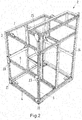
- Fig. 2 is a perspective view on the framework 2 of Fig. 1 only. Further aluminium profile rods and connections and stiffening members are shown. Selected features are designated with the same reference numbers as in Fig. 1 .
- Fig. 1 moreover shows mounting plates 27, 29, 30 which are fixed to the framework 2.
- the mounting plates are fixed to an internal side of the profile rods 3 - 10, because Fig. 1 shows the outer side of the cubicle 1 and the observer first seas the profile rods and then the mounting plates 27 - 30, which are located behind the profile rods.
- Fig. 3 shows a view from the bottom (direction in arrow Z in Fig. 1 ) into the interior of the cubicle 1. Shown are mounting plates 31, 33 and 34 for plugs to realise the electrical connection to a cable duct on the sidewall inside the locomotive.
- a further mounting plate 35 is shown which has four groove-shaped recessions 36, 37, 38,39.
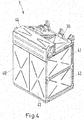
- Fig. 4 shows a perspective view on the cubicle 1 from another side. Further mounting plates 40, 41, 42, 44 are shown wherein each of these mounting plates also has several groove-shaped recessions, as mounting plate 35 in Fig. 3 . On each of said mounting plates 40, 41, 42, 44 groove-shaped recessions are arranged in an X-type arrangement but not designated with reference symbols.
- Fig. 5 shows a method of assembly of a cubicle 1.
- a first assembly block 45 is formed.
- electrical components 46 and 47 are assembled on mounting plate 27 and electrical components 48 and 49 are fixed to mounting plate 50 and electrical component 51 is also fixed to mounting plate 50. Only some of the electrical components are shown or designated with reference numbers. Further electrical components can be present. Moreover mechanical components can be fixed to mounting plates.
- mounting plates 50, 27 with the electrical components fixed thereon are fixed to aluminium profile rods. Aluminium profile rods 5, 53, 54, 55 are designated with reference numbers.
- profile rods are connected to each other to form a part of the framework 2, which is shown in Fig. 5 in assembly block 45.
- Assembly block 57 comprises mounting plates 58, 60 and electrical components 61, 62, 63, 64.
- Fig. 6 shows fastening means that are suitable for connecting aluminium profile rods or that are also suitable for connecting mounting plates with aluminium profile rods.
- Fig. 6 shows a first profile rod 3 and a part of a second profile rod 4.
- Profile rod 3 is shown in longitudinal direction.
- Profile rod 4 is shown in a cross section.
- Profile rod 4 comprises a T-slot 65.
- Profile rod 3 also comprises a T-slot 66 which is cut open in this figure, i.e. flanks 67, 68 of a T-slot are not shown in T-slot 66.
- a screw collar 69 is screwed into the T-slot 66.
- a slot nut 70 is inserted into the T-slot 65 of profile rod 4.
- a screw 71 is inserted into the screw collar 69 and fits with its head 72 at the end of the screw collar 69. When the screw 71 is turned, it is screwed into the slot nut 70 which presses against the flanks 67, 68. In result, both profile rods 3, 4 are pressed and fixed against each other.
- the fastening means 69, 70, 71, 72 in Fig. 6 are conductive for electric current so that current can flow from profile rod 3 to 4 or from 4 to 3. If mounting plates which were shown before are also made from a metal, electric current can flow from electrical components to a mounting plate and from a mounting plate to the profile rods where the mounting plate is fixed. Conductive fastening means enable current flow within the framework 2.
- Fig. 7 shows a rail vehicle 73 with the vehicle body 74.
- the cubicle 1 is fixed to supporting structures 75 which are part of the vehicle body 74. Further cubicles 101, 102 are fixed in the vehicle body 74.
- the framework 2 of the cubicle 1 is electrically connected to the vehicle body 74, as it is the case with the frameworks of cubicles 101, 102.
Landscapes
- Engineering & Computer Science (AREA)
- Power Engineering (AREA)
- Microelectronics & Electronic Packaging (AREA)
- Automation & Control Theory (AREA)
- Transportation (AREA)
- Mechanical Engineering (AREA)
- Patch Boards (AREA)
- Current-Collector Devices For Electrically Propelled Vehicles (AREA)
- Body Structure For Vehicles (AREA)
Abstract
- a framework (2) comprising aluminium profile rods (3, 4, 5, 6, 7, 8, 9, 10, 53, 54, 55, 56) which are connected by detachable connections (11, 12, 13, 14, 15, 16, 17, 18, 19), wherein multiple of said connections are each reinforced by a stiffening member (20, 21, 22, 23, 24, 25, 26), wherein each stiffening member is fixed to the connected profile rods in the region of the connection,
- mounting plates (27, 29, 30, 35, 40, 41, 42, 44, 50, 58, 60) which are fixed to the framework (2)
- electrical components (46, 47, 48, 49, 51) which are fixed to one or more of the mounting plates and which are located inside the framework (2).
Description
- The present invention relates to a cubicle and a rail vehicle wherein said cubicle is installed.
- Electrical cubicles, hereinafter just cubicles, are used in railway vehicles as a cabinet for electrical or electronic equipment. The mechanical construction is the basis for all electrical cubicles. Therefore it is very important to get a concept which is globally feasible and stable. Welding always needs specialists, is expensive and needs long lead time. Premounted standard frames lead to a dependency to a specific supplier. Therefore there is a need for a flexible structure.
- The problem of the invention was to provide with a flexible structure for an electrical cubicle.
- According to a basic idea of the invention, a framework of a cubicle is based on aluminium profiles that are interconnected. Building a framework for a cubicle with aluminium profiles provides with enhanced flexibility in construction. The profiles are fixed to each other in a detachable manner, preferably by screwed joints. This provides with the possibility to make modifications on a finished frame just by replacing or adding profiles. It is also possible to demount the frame for assembling and cabling electrical components inside the cubicle. This leads to more space which will make the process of cubicle and electric component assembly easier and faster. Profiles can be transported as single parts instead of a complete mounted framework which makes logistics easier and cheaper. Using a framework of aluminium-profiles has the following further advantage: different assembly blocks or assembly groups can be produced independently from each other and joined to form the final cubicle including its components. An assembly block may comprise parts of the framework and parts of electrical components of the cubicle. Working with such assembly blocks makes assembly of components easier in comparison to a method wherein in a first step a framework is formed and in a second step electrical components are placed in the framework. This will be further shown in examples. Finally the present invention provides with an easy way of grounding electrical components.
- The present invention particularly provides with a cubicle, comprising
- a framework comprising aluminium profile rods which are connected by detachable connections, wherein multiple of said connections are each reinforced by a stiffening member, wherein each stiffening member is fixed to the connected profile rods in the region of the connection,
- mounting plates which are fixed to the framework
- electrical components which are fixed to one or more of the mounting plates and which are located inside the framework.
- The stiffening member is preferably a metal plate. The stiffening member may be screwed onto connected profile rods. Stiffening members serve to minimize load on connections, especially corner connections. Moreover, stiffening elements help in increasing resonance frequency of the framework.
- Mounting plates are preferably made of metal.
- In one embodiment one or more of the mounting plates have one or more groove-shaped recessions. Such groove-shaped recessions are also called reinforcing seam, stiffening corrugation, crimp or pleat. Groove-shaped recessions provide with following benefits: When electrical components are fixed to mounting plates the weight is increased locally which leads to vibrations. Groove-shaped recessions minimize or reduce such vibrations. Moreover, the recessions lead to a lower global resonance frequency and increased static stability.
- In one embodiment at least one electrical component is electrically contacted to the mounting plate, and the mounting plate is electrically contacted to the framework, so that electrical grounding is provided if the framework is earthed. Several or all electrical components may be contacted, to the same or to different mounting plates. More than one of the mounting plates may be electrically contacted if electrical components are electrically contacted to different mounting plates. This embodiment provides with grounding of at least one of the electrical components or all electrical components via the mounting plate(s) and the framework. This embodiment is beneficial because fixation and electrical grounding is provided by the mounting plate(s). Moreover, the mounting plates have low electrical resistance, or can be chosen to have low electrical resistance, which facilitates electrical grounding. Preferably, one or more of the connections between profile rods are conductive. Even more preferably, the whole framework is conductive without interruptions.
- In one embodiment the profile rods are interconnected by conductive fastening means. This embodiment effects that conductivity between connective profile rods is provided.
- In a further embodiment the mounting plates are fixed to the framework by conductive fastening means. This embodiment effects that electric conductivity between electric components, fixed to mounting plates and the framework is enabled.
- Mentioned conductive fastening means are preferably a conductive slot nut, a conductive screw or a combination thereof.
- Conductive means preferably fulfil standards for electrostatic discharge protection.
- By using conductive fastening means for fixing profiles to each other and for fixing mounting plates to profiles electric conductivity within the cubicle is provided. Therefore, the framework may function as electric collecting pipe for grounding. The framework may be electrically connected with a vehicle body, the mounting plates may be electrically connected to the framework, particularly the profile rods, and the electrical components may be electrically connected to the mounting plates. So, grounding of all components can be ensured.
- In one embodiment the profile rods comprise one or more T-slots. Such slots extend in longitudinal direction of the rods. In this embodiment later fitting of components at the framework is enabled with low effort.
- In a further aspect the invention provides a rail vehicle, comprising a cubicle as described above. The rail vehicle is preferably selected from following rail vehicles: Longs distance trains, near distance trains, suburban trains, subway-trains, streetcars.
- In one embodiment of a rail vehicle, the framework of the cubicle is grounded by electric connection to a vehicle body.
- In a preferred embodiment the framework of the cubicle is fixed to a bottom of a rail vehicle or a bottom of a vehicle body. Grounding can be effected though the bottom, where the framework is fixed and mechanically stabilized. Alternatively, grounding can be effected at another place, for example through a wall.
- Hereinafter the present invention is described with reference to working examples.
-
- Fig. 1
- a cubicle of the invention;
- Fig. 2
- a perspective view on the framework of a cubicle of
Fig. 1 ; - Fig. 3
- a view from the bottom into the interior of a cubicle;
- Fig. 4
- a perspective view on a cubicle from another side;
- Fig. 5
- a method of assembly of a cubicle;
- Fig. 6
- fastening means that are suitable for connecting aluminium profile rods;
- Fig. 7
- a rail vehicle with a cubicle.
-
Fig. 1 shows acubicle 1 of the invention. The cubicle comprises theframework 2. Theframework 2 comprisesaluminium profile rods positions -
Connection 12 is reinforced by a stiffening member, which is a metal plate, 20. Themetal plate 20 is fixed to profilerods Connection 13 is in the same manner reinforced by stiffening member 21,connection 14 by a stiffeningmember 22,connection 15 by a stiffeningmember 23,connection 16 by a stiffeningmember 24,connection 17 by a stiffeningmember 25 andconnection 19 by a stiffeningmember 26. -
Fig. 2 is a perspective view on theframework 2 ofFig. 1 only. Further aluminium profile rods and connections and stiffening members are shown. Selected features are designated with the same reference numbers as inFig. 1 . -
Fig. 1 moreover shows mountingplates framework 2. As can be seen fromFig. 1 , the mounting plates are fixed to an internal side of the profile rods 3 - 10, becauseFig. 1 shows the outer side of thecubicle 1 and the observer first seas the profile rods and then the mounting plates 27 - 30, which are located behind the profile rods. Shown is mountingplate 31 for plugs to realise the electrical connection to a cable duct on the sidewall inside a locomotive. -
Fig. 3 shows a view from the bottom (direction in arrow Z inFig. 1 ) into the interior of thecubicle 1. Shown are mountingplates - A further mounting
plate 35 is shown which has four groove-shapedrecessions -
Fig. 4 shows a perspective view on thecubicle 1 from another side. Further mountingplates plate 35 inFig. 3 . On each of said mountingplates -
Fig. 5 shows a method of assembly of acubicle 1. Afirst assembly block 45 is formed. First,electrical components plate 27 andelectrical components plate 50 andelectrical component 51 is also fixed to mountingplate 50. Only some of the electrical components are shown or designated with reference numbers. Further electrical components can be present. Moreover mechanical components can be fixed to mounting plates. Then, mountingplates Aluminium profile rods framework 2, which is shown inFig. 5 inassembly block 45. - In the same manner, a
second assembly block 57 is pre-formed.Assembly block 57 comprises mountingplates electrical components - When both assembly blocks 45 and 57 are fixed to each other, an intermediate product 1' of the
cubicle 1 ofFig. 1 is obtained. Further method steps can be performed, like mounting of central aluminium profile rods, mounting heavy or balky devices/operators, mounting further preassembled electrical components, finish the remaining cabling and mounting the remaining doors and covers. -
Fig. 6 shows fastening means that are suitable for connecting aluminium profile rods or that are also suitable for connecting mounting plates with aluminium profile rods.Fig. 6 shows afirst profile rod 3 and a part of asecond profile rod 4.Profile rod 3 is shown in longitudinal direction.Profile rod 4 is shown in a cross section. -
Profile rod 4 comprises a T-slot 65.Profile rod 3 also comprises a T-slot 66 which is cut open in this figure, i.e. flanks 67, 68 of a T-slot are not shown in T-slot 66. Ascrew collar 69 is screwed into the T-slot 66. Aslot nut 70 is inserted into the T-slot 65 ofprofile rod 4. Ascrew 71 is inserted into thescrew collar 69 and fits with itshead 72 at the end of thescrew collar 69. When thescrew 71 is turned, it is screwed into theslot nut 70 which presses against theflanks 67, 68. In result, bothprofile rods - The fastening means 69, 70, 71, 72 in
Fig. 6 are conductive for electric current so that current can flow fromprofile rod 3 to 4 or from 4 to 3. If mounting plates which were shown before are also made from a metal, electric current can flow from electrical components to a mounting plate and from a mounting plate to the profile rods where the mounting plate is fixed. Conductive fastening means enable current flow within theframework 2. -
Fig. 7 shows arail vehicle 73 with thevehicle body 74. Thecubicle 1 is fixed to supportingstructures 75 which are part of thevehicle body 74.Further cubicles vehicle body 74. Theframework 2 of thecubicle 1 is electrically connected to thevehicle body 74, as it is the case with the frameworks ofcubicles -
- 1
- Cubicle
- 2
- Framework
- 3
- Aluminium profile rod
- 4
- Aluminium profile rod
- 5
- Aluminium profile rod
- 6
- Aluminium profile rod
- 7
- Aluminium profile rod
- 8
- Aluminium profile rod
- 9
- Aluminium profile rod
- 10
- Aluminium profile rod
- 11
- Detachable connection
- 12
- Detachable connection
- 13
- Detachable connection
- 14
- Detachable connection
- 15
- Detachable connection
- 16
- Detachable connection
- 17
- Detachable connection
- 18
- Detachable connection
- 19
- Detachable connection
- 20
- Stiffening member
- 21
- Stiffening member
- 22
- Stiffening member
- 23
- Stiffening member
- 24
- Stiffening member
- 25
- Stiffening member
- 26
- Stiffening member
- 27
- Mounting plate
- 29
- Mounting plate
- 30
- Mounting plate
- 31
- mounting plate for plug
- 33
- mounting plate for plug
- 34
- mounting plate for plug
- 35
- Mounting plate
- 36
- Groove-shaped recession
- 37
- Groove-shaped recession
- 38
- Groove-shaped recession
- 39
- Groove-shaped recession
- 40
- Mounting plate
- 41
- Mounting plate
- 42
- Mounting plate
- 44
- Mounting plate
- 45
- First assembly block
- 46
- Electrical component
- 47
- Electrical component
- 48
- Electrical component
- 49
- Electrical component
- 50
- Mounting plate
- 51
- Electrical component
- 53
- Aluminium profile rod
- 54
- Aluminium profile rod
- 55
- Aluminium profile rod
- 56
- Aluminium profile rod
- 57
- Second assembly block
- 58
- Mounting plate
- 60
- Mounting plate
- 61
- Electrical component
- 62
- Electrical component
- 63
- Electrical component
- 64
- Electrical component
- 65
- T-slot
- 66
- T-slot
- 67
- flank
- 68
- flank
- 69
- Fastening means - screw collar
- 70
- Fastening means - conductive slot nut
- 71
- Fastening means - conductive screw
- 72
- Fastening means - screw head
- 73
- Rail vehicle
- 74
- Vehicle body
Claims (9)
- Cubicle (1), comprising- a framework (2) comprising aluminium profile rods (3, 4, 5, 6, 7, 8, 9, 10, 53, 54, 55, 56) which are connected by detachable connections (11, 12, 13, 14, 15, 16, 17, 18, 19), wherein multiple of said connections are each reinforced by a stiffening member (20, 21, 22, 23, 24, 25, 26), wherein each stiffening member is fixed to the connected profile rods in the region of the connection,- mounting plates (27, 29, 30, 35, 40, 41, 42, 44, 50, 58, 60) which are fixed to the framework (2)- electrical components (46, 47, 48, 49, 51) which are fixed to one or more of the mounting plates and which are located inside the framework (2)wherein at least one electrical component (46, 47, 48, 49, 51) is electrically contacted to one of the mounting plates (27, 29, 30, 35, 40, 41, 42, 44, 50, 58, 60), and the mounting plate is electrically contacted to the framework (2), so that electrical grounding is provided if the framework (2) is earthed.
- Cubicle (1) according to claim 1, wherein one or more of the mounting plates (27, 29, 30, 35, 40, 41, 42, 44, 50, 58, 60) have one or more groove-shaped recessions (36, 37, 38, 39).
- Cubicle (1) according to one or more of the preceding claims, wherein the profile rods (3, 4, 5, 6, 7, 8, 9, 10, 53, 54, 55, 56) are interconnected by conductive fastening means (69, 70, 71, 72).
- Cubicle (1) according to one or more of the preceding claims, wherein the mounting plates are fixed to the framework (2) by conductive fastening means (69, 70, 71, 72).
- Cubicle (1) according to claim 3 or 4, wherein the conductive fastening means (69, 70, 71, 72) comprises a conductive slot nut (70), a conductive screw (71), or a combination thereof.
- Cubicle (1) according to one or more of the preceding claims, wherein one or more profile rods (3, 4, 5, 6, 7, 8, 9, 10, 53, 54, 55, 56) each comprise one or more T-slots (65, 66).
- Cubicle (1) according to one or more of the preceding claims, wherein the stiffening member (20, 21, 22, 23, 24, 25, 26) is a metal plate.
- Rail vehicle (73), comprising a cubicle (1) according to one of claims 1-7.
- Rail vehicle (73) according to claim 8, wherein the framework (2) is grounded by electric connection to a vehicle body (74).
Priority Applications (1)
| Application Number | Priority Date | Filing Date | Title |
|---|---|---|---|
| PL17170601T PL3252892T3 (en) | 2016-05-31 | 2017-05-11 | Rail vehicle comprising a cubicle |
Applications Claiming Priority (1)
| Application Number | Priority Date | Filing Date | Title |
|---|---|---|---|
| GB1609496.3A GB2550920A (en) | 2016-05-31 | 2016-05-31 | Cubicle and rail vehicle comprising a cubicle |
Publications (2)
| Publication Number | Publication Date |
|---|---|
| EP3252892A1 true EP3252892A1 (en) | 2017-12-06 |
| EP3252892B1 EP3252892B1 (en) | 2021-07-28 |
Family
ID=56410759
Family Applications (1)
| Application Number | Title | Priority Date | Filing Date |
|---|---|---|---|
| EP17170601.3A Active EP3252892B1 (en) | 2016-05-31 | 2017-05-11 | Rail vehicle comprising a cubicle |
Country Status (5)
| Country | Link |
|---|---|
| EP (1) | EP3252892B1 (en) |
| CN (1) | CN107444412B (en) |
| ES (1) | ES2892749T3 (en) |
| GB (1) | GB2550920A (en) |
| PL (1) | PL3252892T3 (en) |
Cited By (1)
| Publication number | Priority date | Publication date | Assignee | Title |
|---|---|---|---|---|
| WO2019201373A1 (en) * | 2018-04-20 | 2019-10-24 | Rittal Gmbh & Co. Kg | Control cabinet assembly having a protective earth function |
Citations (7)
| Publication number | Priority date | Publication date | Assignee | Title |
|---|---|---|---|---|
| US5695263A (en) * | 1993-02-25 | 1997-12-09 | Knurr-Mechanik Fur Die Elektronik Aktiengesellschaft | Cabinet |
| DE29817470U1 (en) * | 1998-09-30 | 1998-11-19 | Fischer-Elektronik GmbH & Co. KG, 58511 Lüdenscheid | Housing frames for electronic devices |
| DE19948329A1 (en) * | 1999-10-07 | 2001-05-17 | Eberhard Gawehn | Electrical cabinet has body with vertical profiles, and attachment device with hooks formed in one piece on hook-bearing component or module plate, especially by being stamped out |
| WO2001061810A1 (en) * | 2000-02-18 | 2001-08-23 | Rittal Gmbh & Co. Kg | Switchgear cabinet |
| WO2008124910A1 (en) * | 2007-04-11 | 2008-10-23 | Melquisedec Francisquini | Improvement introduced in cabinet for telecommunication |
| DE102011006744A1 (en) * | 2011-04-04 | 2012-10-04 | Bombardier Transportation Gmbh | Scaffolding, in particular for electrical equipment in a rail vehicle, and method for producing the scaffold |
| DE102012206321A1 (en) * | 2011-09-13 | 2013-03-14 | Natus Gmbh & Co. Kg | Functional module e.g. switching system module, for constructing e.g. industrial system, has frame manufactured from profile bars, and switching system and transformer integrated in frame and defining function of module |
Family Cites Families (9)
| Publication number | Priority date | Publication date | Assignee | Title |
|---|---|---|---|---|
| US5298681A (en) * | 1992-04-20 | 1994-03-29 | Xerox Corporation | Frame member and assembly for carrying electrical signals and the like |
| DE29619965U1 (en) * | 1996-11-16 | 1997-01-09 | Festo Kg, 73734 Esslingen | Device for connecting three longitudinal elements |
| CN2522489Y (en) * | 2002-03-01 | 2002-11-27 | 陈正义 | Combined partition |
| DE502004002170D1 (en) * | 2004-03-11 | 2007-01-11 | Richard Band | profile connection |
| BRMU8601692Y8 (en) * | 2006-08-17 | 2017-04-04 | Nilko Metalurgia Ltda | cabinet improvements for telecommunications equipment |
| US8891228B2 (en) * | 2011-02-28 | 2014-11-18 | Hubbell Incorporated | Enclosure system and method for facilitating installation of electrical equipment |
| US8985716B2 (en) * | 2012-11-07 | 2015-03-24 | Evans Consoles Corporation | Console module and modular console system |
| FR3025478B1 (en) * | 2014-09-04 | 2018-02-16 | Alstom Transport Technologies | STRUCTURE FOR AN ELECTRICAL INSTALLATION OF A RAILWAY VEHICLE AND ASSOCIATED RAILWAY VEHICLE |
| CN204069539U (en) * | 2014-09-26 | 2014-12-31 | 南车株洲电力机车有限公司 | A kind of regulator cubicle and electric locomotive |
-
2016
- 2016-05-31 GB GB1609496.3A patent/GB2550920A/en not_active Withdrawn
-
2017
- 2017-05-11 EP EP17170601.3A patent/EP3252892B1/en active Active
- 2017-05-11 ES ES17170601T patent/ES2892749T3/en active Active
- 2017-05-11 PL PL17170601T patent/PL3252892T3/en unknown
- 2017-05-25 CN CN201710380705.4A patent/CN107444412B/en active Active
Patent Citations (7)
| Publication number | Priority date | Publication date | Assignee | Title |
|---|---|---|---|---|
| US5695263A (en) * | 1993-02-25 | 1997-12-09 | Knurr-Mechanik Fur Die Elektronik Aktiengesellschaft | Cabinet |
| DE29817470U1 (en) * | 1998-09-30 | 1998-11-19 | Fischer-Elektronik GmbH & Co. KG, 58511 Lüdenscheid | Housing frames for electronic devices |
| DE19948329A1 (en) * | 1999-10-07 | 2001-05-17 | Eberhard Gawehn | Electrical cabinet has body with vertical profiles, and attachment device with hooks formed in one piece on hook-bearing component or module plate, especially by being stamped out |
| WO2001061810A1 (en) * | 2000-02-18 | 2001-08-23 | Rittal Gmbh & Co. Kg | Switchgear cabinet |
| WO2008124910A1 (en) * | 2007-04-11 | 2008-10-23 | Melquisedec Francisquini | Improvement introduced in cabinet for telecommunication |
| DE102011006744A1 (en) * | 2011-04-04 | 2012-10-04 | Bombardier Transportation Gmbh | Scaffolding, in particular for electrical equipment in a rail vehicle, and method for producing the scaffold |
| DE102012206321A1 (en) * | 2011-09-13 | 2013-03-14 | Natus Gmbh & Co. Kg | Functional module e.g. switching system module, for constructing e.g. industrial system, has frame manufactured from profile bars, and switching system and transformer integrated in frame and defining function of module |
Cited By (2)
| Publication number | Priority date | Publication date | Assignee | Title |
|---|---|---|---|---|
| WO2019201373A1 (en) * | 2018-04-20 | 2019-10-24 | Rittal Gmbh & Co. Kg | Control cabinet assembly having a protective earth function |
| DE102018109601B4 (en) | 2018-04-20 | 2024-05-23 | Rittal Gmbh & Co. Kg | Control cabinet arrangement with protective conductor function |
Also Published As
| Publication number | Publication date |
|---|---|
| CN107444412A (en) | 2017-12-08 |
| ES2892749T3 (en) | 2022-02-04 |
| PL3252892T3 (en) | 2022-01-31 |
| EP3252892B1 (en) | 2021-07-28 |
| GB201609496D0 (en) | 2016-07-13 |
| GB2550920A (en) | 2017-12-06 |
| CN107444412B (en) | 2020-02-21 |
Similar Documents
| Publication | Publication Date | Title |
|---|---|---|
| JP6444605B2 (en) | Inverter-integrated electric compressor | |
| JP5054991B2 (en) | Busbar connection structure and inverter-integrated electric compressor | |
| CN103026424B (en) | Wire harness, method of transporting wire harness with equipment, and method of connecting equipment with wire harness | |
| US8422222B2 (en) | Power conversion apparatus | |
| US7537467B1 (en) | Grounding terminal block assembly for multiple services | |
| CN107154470B (en) | Battery pack and vehicle with such a battery pack | |
| CN104349930B (en) | Connection structure between main transformer and high-voltage equipment box and railway vehicle with the connection structure | |
| DE112013006238T5 (en) | Gleichtrom / DC converter | |
| US8410378B1 (en) | Grounding fitting | |
| EP3252892B1 (en) | Rail vehicle comprising a cubicle | |
| US10369940B2 (en) | Bracket for and method of forming a wire harness assembly | |
| KR102146064B1 (en) | Connecting bracket of distribution panel and distribution panel having the same | |
| US20140283513A1 (en) | Brake Control Apparatus | |
| WO2018001890A1 (en) | Cable tray assembly for a vehicle body of a rail vehicle and its method of assembly | |
| US10826247B1 (en) | Electromagnetic shielding systems and methods for aircraft | |
| CN111712069B (en) | Airborne equipment protection device | |
| EP2953219B1 (en) | Gas-insulated switchgear | |
| EP3267539A1 (en) | Method of installing electrical device assembly, and electrical device assembly | |
| DE102013201470B4 (en) | Electrical machine with electrical conductor | |
| CN205724501U (en) | Pin-connected panel distribution box | |
| CN203632421U (en) | Integrated end cover assembly | |
| JP7154397B2 (en) | Power converter for railway vehicles | |
| CN209516383U (en) | A double voltage transformer cabinet | |
| US20040239215A1 (en) | Cabinet for electronic equipment | |
| CN104348120A (en) | High voltage common bus |
Legal Events
| Date | Code | Title | Description |
|---|---|---|---|
| PUAI | Public reference made under article 153(3) epc to a published international application that has entered the european phase |
Free format text: ORIGINAL CODE: 0009012 |
|
| STAA | Information on the status of an ep patent application or granted ep patent |
Free format text: STATUS: THE APPLICATION HAS BEEN PUBLISHED |
|
| AK | Designated contracting states |
Kind code of ref document: A1 Designated state(s): AL AT BE BG CH CY CZ DE DK EE ES FI FR GB GR HR HU IE IS IT LI LT LU LV MC MK MT NL NO PL PT RO RS SE SI SK SM TR |
|
| AX | Request for extension of the european patent |
Extension state: BA ME |
|
| STAA | Information on the status of an ep patent application or granted ep patent |
Free format text: STATUS: REQUEST FOR EXAMINATION WAS MADE |
|
| 17P | Request for examination filed |
Effective date: 20180605 |
|
| RBV | Designated contracting states (corrected) |
Designated state(s): AL AT BE BG CH CY CZ DE DK EE ES FI FR GB GR HR HU IE IS IT LI LT LU LV MC MK MT NL NO PL PT RO RS SE SI SK SM TR |
|
| STAA | Information on the status of an ep patent application or granted ep patent |
Free format text: STATUS: EXAMINATION IS IN PROGRESS |
|
| 17Q | First examination report despatched |
Effective date: 20191211 |
|
| GRAP | Despatch of communication of intention to grant a patent |
Free format text: ORIGINAL CODE: EPIDOSNIGR1 |
|
| STAA | Information on the status of an ep patent application or granted ep patent |
Free format text: STATUS: GRANT OF PATENT IS INTENDED |
|
| RIC1 | Information provided on ipc code assigned before grant |
Ipc: H02B 1/01 20060101AFI20210218BHEP Ipc: H02B 1/30 20060101ALI20210218BHEP Ipc: H02B 1/32 20060101ALI20210218BHEP Ipc: H02B 1/16 20060101ALI20210218BHEP Ipc: F16B 7/18 20060101ALN20210218BHEP |
|
| RIC1 | Information provided on ipc code assigned before grant |
Ipc: H02B 1/30 20060101ALI20210301BHEP Ipc: H02B 1/16 20060101ALI20210301BHEP Ipc: F16B 7/18 20060101ALN20210301BHEP Ipc: H02B 1/01 20060101AFI20210301BHEP Ipc: H02B 1/32 20060101ALI20210301BHEP |
|
| INTG | Intention to grant announced |
Effective date: 20210317 |
|
| GRAS | Grant fee paid |
Free format text: ORIGINAL CODE: EPIDOSNIGR3 |
|
| GRAA | (expected) grant |
Free format text: ORIGINAL CODE: 0009210 |
|
| STAA | Information on the status of an ep patent application or granted ep patent |
Free format text: STATUS: THE PATENT HAS BEEN GRANTED |
|
| AK | Designated contracting states |
Kind code of ref document: B1 Designated state(s): AL AT BE BG CH CY CZ DE DK EE ES FI FR GB GR HR HU IE IS IT LI LT LU LV MC MK MT NL NO PL PT RO RS SE SI SK SM TR |
|
| RAP3 | Party data changed (applicant data changed or rights of an application transferred) |
Owner name: BOMBARDIER TRANSPORTATION GMBH |
|
| REG | Reference to a national code |
Ref country code: GB Ref legal event code: FG4D |
|
| REG | Reference to a national code |
Ref country code: CH Ref legal event code: EP |
|
| REG | Reference to a national code |
Ref country code: AT Ref legal event code: REF Ref document number: 1415564 Country of ref document: AT Kind code of ref document: T Effective date: 20210815 |
|
| REG | Reference to a national code |
Ref country code: IE Ref legal event code: FG4D |
|
| REG | Reference to a national code |
Ref country code: DE Ref legal event code: R096 Ref document number: 602017042780 Country of ref document: DE |
|
| REG | Reference to a national code |
Ref country code: SE Ref legal event code: TRGR |
|
| REG | Reference to a national code |
Ref country code: NL Ref legal event code: FP |
|
| REG | Reference to a national code |
Ref country code: LT Ref legal event code: MG9D |
|
| PG25 | Lapsed in a contracting state [announced via postgrant information from national office to epo] |
Ref country code: RS Free format text: LAPSE BECAUSE OF FAILURE TO SUBMIT A TRANSLATION OF THE DESCRIPTION OR TO PAY THE FEE WITHIN THE PRESCRIBED TIME-LIMIT Effective date: 20210728 Ref country code: NO Free format text: LAPSE BECAUSE OF FAILURE TO SUBMIT A TRANSLATION OF THE DESCRIPTION OR TO PAY THE FEE WITHIN THE PRESCRIBED TIME-LIMIT Effective date: 20211028 Ref country code: PT Free format text: LAPSE BECAUSE OF FAILURE TO SUBMIT A TRANSLATION OF THE DESCRIPTION OR TO PAY THE FEE WITHIN THE PRESCRIBED TIME-LIMIT Effective date: 20211129 Ref country code: HR Free format text: LAPSE BECAUSE OF FAILURE TO SUBMIT A TRANSLATION OF THE DESCRIPTION OR TO PAY THE FEE WITHIN THE PRESCRIBED TIME-LIMIT Effective date: 20210728 Ref country code: FI Free format text: LAPSE BECAUSE OF FAILURE TO SUBMIT A TRANSLATION OF THE DESCRIPTION OR TO PAY THE FEE WITHIN THE PRESCRIBED TIME-LIMIT Effective date: 20210728 Ref country code: BG Free format text: LAPSE BECAUSE OF FAILURE TO SUBMIT A TRANSLATION OF THE DESCRIPTION OR TO PAY THE FEE WITHIN THE PRESCRIBED TIME-LIMIT Effective date: 20211028 Ref country code: LT Free format text: LAPSE BECAUSE OF FAILURE TO SUBMIT A TRANSLATION OF THE DESCRIPTION OR TO PAY THE FEE WITHIN THE PRESCRIBED TIME-LIMIT Effective date: 20210728 |
|
| REG | Reference to a national code |
Ref country code: ES Ref legal event code: FG2A Ref document number: 2892749 Country of ref document: ES Kind code of ref document: T3 Effective date: 20220204 |
|
| PG25 | Lapsed in a contracting state [announced via postgrant information from national office to epo] |
Ref country code: LV Free format text: LAPSE BECAUSE OF FAILURE TO SUBMIT A TRANSLATION OF THE DESCRIPTION OR TO PAY THE FEE WITHIN THE PRESCRIBED TIME-LIMIT Effective date: 20210728 Ref country code: GR Free format text: LAPSE BECAUSE OF FAILURE TO SUBMIT A TRANSLATION OF THE DESCRIPTION OR TO PAY THE FEE WITHIN THE PRESCRIBED TIME-LIMIT Effective date: 20211029 |
|
| PG25 | Lapsed in a contracting state [announced via postgrant information from national office to epo] |
Ref country code: DK Free format text: LAPSE BECAUSE OF FAILURE TO SUBMIT A TRANSLATION OF THE DESCRIPTION OR TO PAY THE FEE WITHIN THE PRESCRIBED TIME-LIMIT Effective date: 20210728 |
|
| REG | Reference to a national code |
Ref country code: DE Ref legal event code: R097 Ref document number: 602017042780 Country of ref document: DE |
|
| PG25 | Lapsed in a contracting state [announced via postgrant information from national office to epo] |
Ref country code: SM Free format text: LAPSE BECAUSE OF FAILURE TO SUBMIT A TRANSLATION OF THE DESCRIPTION OR TO PAY THE FEE WITHIN THE PRESCRIBED TIME-LIMIT Effective date: 20210728 Ref country code: SK Free format text: LAPSE BECAUSE OF FAILURE TO SUBMIT A TRANSLATION OF THE DESCRIPTION OR TO PAY THE FEE WITHIN THE PRESCRIBED TIME-LIMIT Effective date: 20210728 Ref country code: RO Free format text: LAPSE BECAUSE OF FAILURE TO SUBMIT A TRANSLATION OF THE DESCRIPTION OR TO PAY THE FEE WITHIN THE PRESCRIBED TIME-LIMIT Effective date: 20210728 Ref country code: EE Free format text: LAPSE BECAUSE OF FAILURE TO SUBMIT A TRANSLATION OF THE DESCRIPTION OR TO PAY THE FEE WITHIN THE PRESCRIBED TIME-LIMIT Effective date: 20210728 Ref country code: AL Free format text: LAPSE BECAUSE OF FAILURE TO SUBMIT A TRANSLATION OF THE DESCRIPTION OR TO PAY THE FEE WITHIN THE PRESCRIBED TIME-LIMIT Effective date: 20210728 |
|
| PLBE | No opposition filed within time limit |
Free format text: ORIGINAL CODE: 0009261 |
|
| STAA | Information on the status of an ep patent application or granted ep patent |
Free format text: STATUS: NO OPPOSITION FILED WITHIN TIME LIMIT |
|
| 26N | No opposition filed |
Effective date: 20220429 |
|
| REG | Reference to a national code |
Ref country code: AT Ref legal event code: UEP Ref document number: 1415564 Country of ref document: AT Kind code of ref document: T Effective date: 20210728 |
|
| REG | Reference to a national code |
Ref country code: BE Ref legal event code: MM Effective date: 20220531 |
|
| PG25 | Lapsed in a contracting state [announced via postgrant information from national office to epo] |
Ref country code: MC Free format text: LAPSE BECAUSE OF FAILURE TO SUBMIT A TRANSLATION OF THE DESCRIPTION OR TO PAY THE FEE WITHIN THE PRESCRIBED TIME-LIMIT Effective date: 20210728 Ref country code: LU Free format text: LAPSE BECAUSE OF NON-PAYMENT OF DUE FEES Effective date: 20220511 |
|
| PG25 | Lapsed in a contracting state [announced via postgrant information from national office to epo] |
Ref country code: BE Free format text: LAPSE BECAUSE OF NON-PAYMENT OF DUE FEES Effective date: 20220531 |
|
| P01 | Opt-out of the competence of the unified patent court (upc) registered |
Effective date: 20230822 |
|
| PG25 | Lapsed in a contracting state [announced via postgrant information from national office to epo] |
Ref country code: HU Free format text: LAPSE BECAUSE OF FAILURE TO SUBMIT A TRANSLATION OF THE DESCRIPTION OR TO PAY THE FEE WITHIN THE PRESCRIBED TIME-LIMIT; INVALID AB INITIO Effective date: 20170511 |
|
| PG25 | Lapsed in a contracting state [announced via postgrant information from national office to epo] |
Ref country code: MK Free format text: LAPSE BECAUSE OF FAILURE TO SUBMIT A TRANSLATION OF THE DESCRIPTION OR TO PAY THE FEE WITHIN THE PRESCRIBED TIME-LIMIT Effective date: 20210728 Ref country code: CY Free format text: LAPSE BECAUSE OF FAILURE TO SUBMIT A TRANSLATION OF THE DESCRIPTION OR TO PAY THE FEE WITHIN THE PRESCRIBED TIME-LIMIT Effective date: 20210728 |
|
| PG25 | Lapsed in a contracting state [announced via postgrant information from national office to epo] |
Ref country code: TR Free format text: LAPSE BECAUSE OF FAILURE TO SUBMIT A TRANSLATION OF THE DESCRIPTION OR TO PAY THE FEE WITHIN THE PRESCRIBED TIME-LIMIT Effective date: 20210728 |
|
| PG25 | Lapsed in a contracting state [announced via postgrant information from national office to epo] |
Ref country code: MT Free format text: LAPSE BECAUSE OF FAILURE TO SUBMIT A TRANSLATION OF THE DESCRIPTION OR TO PAY THE FEE WITHIN THE PRESCRIBED TIME-LIMIT Effective date: 20210728 |
|
| PGFP | Annual fee paid to national office [announced via postgrant information from national office to epo] |
Ref country code: ES Payment date: 20250627 Year of fee payment: 9 |
|
| PGFP | Annual fee paid to national office [announced via postgrant information from national office to epo] |
Ref country code: GB Payment date: 20260306 Year of fee payment: 10 |
|
| REG | Reference to a national code |
Ref country code: CH Ref legal event code: U11 Free format text: ST27 STATUS EVENT CODE: U-0-0-U10-U11 (AS PROVIDED BY THE NATIONAL OFFICE) Effective date: 20260601 |
|
| PGFP | Annual fee paid to national office [announced via postgrant information from national office to epo] |
Ref country code: NL Payment date: 20260520 Year of fee payment: 10 |
|
| PGFP | Annual fee paid to national office [announced via postgrant information from national office to epo] |
Ref country code: PL Payment date: 20260505 Year of fee payment: 10 |
|
| PGFP | Annual fee paid to national office [announced via postgrant information from national office to epo] |
Ref country code: IT Payment date: 20260525 Year of fee payment: 10 |
|
| PGFP | Annual fee paid to national office [announced via postgrant information from national office to epo] |
Ref country code: DE Payment date: 20260522 Year of fee payment: 10 |
|
| PGFP | Annual fee paid to national office [announced via postgrant information from national office to epo] |
Ref country code: AT Payment date: 20260521 Year of fee payment: 10 Ref country code: SE Payment date: 20260520 Year of fee payment: 10 |
|
| PGFP | Annual fee paid to national office [announced via postgrant information from national office to epo] |
Ref country code: IE Payment date: 20260522 Year of fee payment: 10 Ref country code: CH Payment date: 20260601 Year of fee payment: 10 |
|
| PGFP | Annual fee paid to national office [announced via postgrant information from national office to epo] |
Ref country code: CZ Payment date: 20260507 Year of fee payment: 10 |
|
| PGFP | Annual fee paid to national office [announced via postgrant information from national office to epo] |
Ref country code: FR Payment date: 20260526 Year of fee payment: 10 |