EP3252858A1 - Fuel cell and method for operating the same - Google Patents
Fuel cell and method for operating the same Download PDFInfo
- Publication number
- EP3252858A1 EP3252858A1 EP17172471.9A EP17172471A EP3252858A1 EP 3252858 A1 EP3252858 A1 EP 3252858A1 EP 17172471 A EP17172471 A EP 17172471A EP 3252858 A1 EP3252858 A1 EP 3252858A1
- Authority
- EP
- European Patent Office
- Prior art keywords
- fuel
- air
- inlet
- feeder
- outlet port
- Prior art date
- Legal status (The legal status is an assumption and is not a legal conclusion. Google has not performed a legal analysis and makes no representation as to the accuracy of the status listed.)
- Granted
Links
- 239000000446 fuel Substances 0.000 title claims abstract description 434
- 238000000034 method Methods 0.000 title claims abstract description 17
- 238000001816 cooling Methods 0.000 claims description 17
- 239000003792 electrolyte Substances 0.000 claims description 16
- 239000012528 membrane Substances 0.000 claims description 16
- 238000007599 discharging Methods 0.000 claims description 2
- 239000012535 impurity Substances 0.000 abstract description 26
- 238000013021 overheating Methods 0.000 abstract description 4
- OKKJLVBELUTLKV-UHFFFAOYSA-N Methanol Chemical compound OC OKKJLVBELUTLKV-UHFFFAOYSA-N 0.000 description 15
- UFHFLCQGNIYNRP-UHFFFAOYSA-N Hydrogen Chemical compound [H][H] UFHFLCQGNIYNRP-UHFFFAOYSA-N 0.000 description 6
- NBIIXXVUZAFLBC-UHFFFAOYSA-N Phosphoric acid Chemical compound OP(O)(O)=O NBIIXXVUZAFLBC-UHFFFAOYSA-N 0.000 description 6
- 239000001257 hydrogen Substances 0.000 description 6
- 229910052739 hydrogen Inorganic materials 0.000 description 6
- 238000010926 purge Methods 0.000 description 6
- LFQSCWFLJHTTHZ-UHFFFAOYSA-N Ethanol Chemical compound CCO LFQSCWFLJHTTHZ-UHFFFAOYSA-N 0.000 description 5
- QVGXLLKOCUKJST-UHFFFAOYSA-N atomic oxygen Chemical compound [O] QVGXLLKOCUKJST-UHFFFAOYSA-N 0.000 description 5
- 239000001301 oxygen Substances 0.000 description 5
- 229910052760 oxygen Inorganic materials 0.000 description 5
- 238000006243 chemical reaction Methods 0.000 description 4
- 230000002708 enhancing effect Effects 0.000 description 4
- 239000012530 fluid Substances 0.000 description 4
- 239000007789 gas Substances 0.000 description 4
- 239000004215 Carbon black (E152) Substances 0.000 description 3
- BVKZGUZCCUSVTD-UHFFFAOYSA-L Carbonate Chemical compound [O-]C([O-])=O BVKZGUZCCUSVTD-UHFFFAOYSA-L 0.000 description 3
- 229910000147 aluminium phosphate Inorganic materials 0.000 description 3
- 229930195733 hydrocarbon Natural products 0.000 description 3
- 150000002430 hydrocarbons Chemical class 0.000 description 3
- 239000007787 solid Substances 0.000 description 3
- IJGRMHOSHXDMSA-UHFFFAOYSA-N Atomic nitrogen Chemical compound N#N IJGRMHOSHXDMSA-UHFFFAOYSA-N 0.000 description 2
- 238000009825 accumulation Methods 0.000 description 2
- 230000015556 catabolic process Effects 0.000 description 2
- 238000006731 degradation reaction Methods 0.000 description 2
- 238000003487 electrochemical reaction Methods 0.000 description 2
- 230000001965 increasing effect Effects 0.000 description 2
- 239000003915 liquefied petroleum gas Substances 0.000 description 2
- 239000007788 liquid Substances 0.000 description 2
- VNWKTOKETHGBQD-UHFFFAOYSA-N methane Chemical compound C VNWKTOKETHGBQD-UHFFFAOYSA-N 0.000 description 2
- 238000012986 modification Methods 0.000 description 2
- 230000004048 modification Effects 0.000 description 2
- 239000005518 polymer electrolyte Substances 0.000 description 2
- 239000003513 alkali Substances 0.000 description 1
- 239000001273 butane Substances 0.000 description 1
- 239000000498 cooling water Substances 0.000 description 1
- 230000010485 coping Effects 0.000 description 1
- 230000007423 decrease Effects 0.000 description 1
- 230000006866 deterioration Effects 0.000 description 1
- 238000011161 development Methods 0.000 description 1
- 238000010586 diagram Methods 0.000 description 1
- 230000005611 electricity Effects 0.000 description 1
- 239000002803 fossil fuel Substances 0.000 description 1
- 239000003502 gasoline Substances 0.000 description 1
- 150000002431 hydrogen Chemical class 0.000 description 1
- 239000003949 liquefied natural gas Substances 0.000 description 1
- IJDNQMDRQITEOD-UHFFFAOYSA-N n-butane Chemical compound CCCC IJDNQMDRQITEOD-UHFFFAOYSA-N 0.000 description 1
- OFBQJSOFQDEBGM-UHFFFAOYSA-N n-pentane Natural products CCCCC OFBQJSOFQDEBGM-UHFFFAOYSA-N 0.000 description 1
- 239000003345 natural gas Substances 0.000 description 1
- 229910052757 nitrogen Inorganic materials 0.000 description 1
- 238000011017 operating method Methods 0.000 description 1
- 230000003647 oxidation Effects 0.000 description 1
- 238000007254 oxidation reaction Methods 0.000 description 1
- 238000005406 washing Methods 0.000 description 1
Images





Classifications
-
- H—ELECTRICITY
- H01—ELECTRIC ELEMENTS
- H01M—PROCESSES OR MEANS, e.g. BATTERIES, FOR THE DIRECT CONVERSION OF CHEMICAL ENERGY INTO ELECTRICAL ENERGY
- H01M8/00—Fuel cells; Manufacture thereof
- H01M8/04—Auxiliary arrangements, e.g. for control of pressure or for circulation of fluids
- H01M8/04082—Arrangements for control of reactant parameters, e.g. pressure or concentration
- H01M8/04089—Arrangements for control of reactant parameters, e.g. pressure or concentration of gaseous reactants
-
- H—ELECTRICITY
- H01—ELECTRIC ELEMENTS
- H01M—PROCESSES OR MEANS, e.g. BATTERIES, FOR THE DIRECT CONVERSION OF CHEMICAL ENERGY INTO ELECTRICAL ENERGY
- H01M8/00—Fuel cells; Manufacture thereof
- H01M8/04—Auxiliary arrangements, e.g. for control of pressure or for circulation of fluids
- H01M8/04298—Processes for controlling fuel cells or fuel cell systems
- H01M8/04694—Processes for controlling fuel cells or fuel cell systems characterised by variables to be controlled
- H01M8/04746—Pressure; Flow
- H01M8/04753—Pressure; Flow of fuel cell reactants
-
- H—ELECTRICITY
- H01—ELECTRIC ELEMENTS
- H01M—PROCESSES OR MEANS, e.g. BATTERIES, FOR THE DIRECT CONVERSION OF CHEMICAL ENERGY INTO ELECTRICAL ENERGY
- H01M8/00—Fuel cells; Manufacture thereof
- H01M8/04—Auxiliary arrangements, e.g. for control of pressure or for circulation of fluids
- H01M8/04082—Arrangements for control of reactant parameters, e.g. pressure or concentration
- H01M8/04186—Arrangements for control of reactant parameters, e.g. pressure or concentration of liquid-charged or electrolyte-charged reactants
-
- H—ELECTRICITY
- H01—ELECTRIC ELEMENTS
- H01M—PROCESSES OR MEANS, e.g. BATTERIES, FOR THE DIRECT CONVERSION OF CHEMICAL ENERGY INTO ELECTRICAL ENERGY
- H01M8/00—Fuel cells; Manufacture thereof
- H01M8/04—Auxiliary arrangements, e.g. for control of pressure or for circulation of fluids
- H01M8/04082—Arrangements for control of reactant parameters, e.g. pressure or concentration
- H01M8/04197—Preventing means for fuel crossover
-
- H—ELECTRICITY
- H01—ELECTRIC ELEMENTS
- H01M—PROCESSES OR MEANS, e.g. BATTERIES, FOR THE DIRECT CONVERSION OF CHEMICAL ENERGY INTO ELECTRICAL ENERGY
- H01M8/00—Fuel cells; Manufacture thereof
- H01M8/04—Auxiliary arrangements, e.g. for control of pressure or for circulation of fluids
- H01M8/04082—Arrangements for control of reactant parameters, e.g. pressure or concentration
- H01M8/04201—Reactant storage and supply, e.g. means for feeding, pipes
-
- H—ELECTRICITY
- H01—ELECTRIC ELEMENTS
- H01M—PROCESSES OR MEANS, e.g. BATTERIES, FOR THE DIRECT CONVERSION OF CHEMICAL ENERGY INTO ELECTRICAL ENERGY
- H01M8/00—Fuel cells; Manufacture thereof
- H01M8/04—Auxiliary arrangements, e.g. for control of pressure or for circulation of fluids
- H01M8/04223—Auxiliary arrangements, e.g. for control of pressure or for circulation of fluids during start-up or shut-down; Depolarisation or activation, e.g. purging; Means for short-circuiting defective fuel cells
- H01M8/04231—Purging of the reactants
-
- H—ELECTRICITY
- H01—ELECTRIC ELEMENTS
- H01M—PROCESSES OR MEANS, e.g. BATTERIES, FOR THE DIRECT CONVERSION OF CHEMICAL ENERGY INTO ELECTRICAL ENERGY
- H01M8/00—Fuel cells; Manufacture thereof
- H01M8/04—Auxiliary arrangements, e.g. for control of pressure or for circulation of fluids
- H01M8/04298—Processes for controlling fuel cells or fuel cell systems
- H01M8/04313—Processes for controlling fuel cells or fuel cell systems characterised by the detection or assessment of variables; characterised by the detection or assessment of failure or abnormal function
- H01M8/0432—Temperature; Ambient temperature
-
- H—ELECTRICITY
- H01—ELECTRIC ELEMENTS
- H01M—PROCESSES OR MEANS, e.g. BATTERIES, FOR THE DIRECT CONVERSION OF CHEMICAL ENERGY INTO ELECTRICAL ENERGY
- H01M8/00—Fuel cells; Manufacture thereof
- H01M8/04—Auxiliary arrangements, e.g. for control of pressure or for circulation of fluids
- H01M8/04298—Processes for controlling fuel cells or fuel cell systems
- H01M8/04313—Processes for controlling fuel cells or fuel cell systems characterised by the detection or assessment of variables; characterised by the detection or assessment of failure or abnormal function
- H01M8/0432—Temperature; Ambient temperature
- H01M8/04365—Temperature; Ambient temperature of other components of a fuel cell or fuel cell stacks
-
- H—ELECTRICITY
- H01—ELECTRIC ELEMENTS
- H01M—PROCESSES OR MEANS, e.g. BATTERIES, FOR THE DIRECT CONVERSION OF CHEMICAL ENERGY INTO ELECTRICAL ENERGY
- H01M8/00—Fuel cells; Manufacture thereof
- H01M8/04—Auxiliary arrangements, e.g. for control of pressure or for circulation of fluids
- H01M8/04298—Processes for controlling fuel cells or fuel cell systems
- H01M8/04313—Processes for controlling fuel cells or fuel cell systems characterised by the detection or assessment of variables; characterised by the detection or assessment of failure or abnormal function
- H01M8/04537—Electric variables
- H01M8/04604—Power, energy, capacity or load
- H01M8/04619—Power, energy, capacity or load of fuel cell stacks
-
- H—ELECTRICITY
- H01—ELECTRIC ELEMENTS
- H01M—PROCESSES OR MEANS, e.g. BATTERIES, FOR THE DIRECT CONVERSION OF CHEMICAL ENERGY INTO ELECTRICAL ENERGY
- H01M8/00—Fuel cells; Manufacture thereof
- H01M8/04—Auxiliary arrangements, e.g. for control of pressure or for circulation of fluids
- H01M8/04298—Processes for controlling fuel cells or fuel cell systems
- H01M8/04313—Processes for controlling fuel cells or fuel cell systems characterised by the detection or assessment of variables; characterised by the detection or assessment of failure or abnormal function
- H01M8/04664—Failure or abnormal function
- H01M8/04679—Failure or abnormal function of fuel cell stacks
-
- H—ELECTRICITY
- H01—ELECTRIC ELEMENTS
- H01M—PROCESSES OR MEANS, e.g. BATTERIES, FOR THE DIRECT CONVERSION OF CHEMICAL ENERGY INTO ELECTRICAL ENERGY
- H01M8/00—Fuel cells; Manufacture thereof
- H01M8/04—Auxiliary arrangements, e.g. for control of pressure or for circulation of fluids
- H01M8/04082—Arrangements for control of reactant parameters, e.g. pressure or concentration
- H01M8/04089—Arrangements for control of reactant parameters, e.g. pressure or concentration of gaseous reactants
- H01M8/04119—Arrangements for control of reactant parameters, e.g. pressure or concentration of gaseous reactants with simultaneous supply or evacuation of electrolyte; Humidifying or dehumidifying
- H01M8/04156—Arrangements for control of reactant parameters, e.g. pressure or concentration of gaseous reactants with simultaneous supply or evacuation of electrolyte; Humidifying or dehumidifying with product water removal
- H01M8/04179—Arrangements for control of reactant parameters, e.g. pressure or concentration of gaseous reactants with simultaneous supply or evacuation of electrolyte; Humidifying or dehumidifying with product water removal by purging or increasing flow or pressure of reactants
-
- Y—GENERAL TAGGING OF NEW TECHNOLOGICAL DEVELOPMENTS; GENERAL TAGGING OF CROSS-SECTIONAL TECHNOLOGIES SPANNING OVER SEVERAL SECTIONS OF THE IPC; TECHNICAL SUBJECTS COVERED BY FORMER USPC CROSS-REFERENCE ART COLLECTIONS [XRACs] AND DIGESTS
- Y02—TECHNOLOGIES OR APPLICATIONS FOR MITIGATION OR ADAPTATION AGAINST CLIMATE CHANGE
- Y02E—REDUCTION OF GREENHOUSE GAS [GHG] EMISSIONS, RELATED TO ENERGY GENERATION, TRANSMISSION OR DISTRIBUTION
- Y02E60/00—Enabling technologies; Technologies with a potential or indirect contribution to GHG emissions mitigation
- Y02E60/30—Hydrogen technology
- Y02E60/50—Fuel cells
Definitions
- This specification relates to a fuel cell, and more particularly, a fuel cell capable of switching supply directions of fuel and air supplied to a stack, and a method for operating the same.
- Fuel cells are under development to replace existing fossil fuels with eco-friendly energy.
- Fuel cells such as home fuel cells for supplying electric power to home, fuel cells for electric vehicles, fuel cells for portable terminals and notebook computers, and fuel cells for supplying electric power in a portable manner at home, are being studied and developed in various application fields.
- Fuel cells are classified, according to a type of electrolyte, into phosphoric acid fuel cell (PAFC), alkaline fuel cell (AFC), proton exchange membrane fuel cell (PEMFC), molten carbonate fuel cell (MCFC), solid oxide fuel cell (SOFC), direct methanol fuel cell (DMFC), direct borohydride fuel cell (DMFC) and the like.
- PAFC phosphoric acid fuel cell
- AFC alkaline fuel cell
- PEMFC proton exchange membrane fuel cell
- MCFC molten carbonate fuel cell
- SOFC solid oxide fuel cell
- DMFC direct methanol fuel cell
- DMFC direct borohydride fuel cell
- operating temperatures of these fuel cells are about 200°C for the phosphoric acid type, 60-110°C for the alkali type, room temperature to 80°C for the polymer electrolyte type, 500 to 700°C for the molten carbonate electrolyte type, high temperature over 1000°C for the solid oxide type and 25 to 130°C for the direct methanol type.
- the fuel cell supplies fuel (hydrogen gas or hydrocarbon) and oxygen to a fuel electrode (anode) and an air electrode (cathode), respectively, which form a stack, thereby arousing an electrochemical reaction between the hydrogen and the oxygen without a burning (oxidation) reaction. Then, an energy difference between before and after the electrochemical reaction is directly converted into electric energy.
- the stack is formed by stacking a plurality of unit cells.
- Each unit cell includes a fuel electrode and an air electrode stacked with interposing an electrolyte membrane therebetween.
- the fuel electrode has a narrow and complicated flow path to evenly disperse the supplied fuel to its entire area. Accordingly, when the fuel cell operates for a long period of time, impurities may be accumulated in the flow path of the fuel electrode, and thereby the flow path may be blocked due to the impurities.
- the impurities are not greatly accumulated in an inlet side of the fuel electrode, more impurities may be accumulated toward an outlet side. Accordingly, a reaction area of fuel and air decreases at the outlet side of the fuel electrode, which causes lowering of energy efficiency.
- the related art fuel cell employs an operating method of executing a main operation after removing impurities by supplying purge gas periodically while a system is stopped or washing the fuel electrode by supplying nitrogen for a predetermined period of time upon starting the system.
- an operation time is shortened and energy efficiency is lowered accordingly.
- the fuel cell generates heat while hydrogen and oxygen as the fuel react with each other, and the temperature at the outlet side of the flow path (air electrode) becomes the highest due to the heat generated during the reaction and a continuous flow of fluid. Accordingly, the temperature at the outlet side of the air electrode is locally increased, which may cause the electrolyte membranes of some of the unit cells to be broken. If the electrolyte membrane is broken, the unit cell should be replaced or, in severe cases, the use of the entire stack is restricted. This causes lowering of the energy efficiency.
- the fuel cell is provided with an air-cooling or water-cooling type cooling device, but the related art cooling device cools the entire stack. However, the related art cooling device is not suitable for cooling a locally heated portion and even the cooling operation is carried out for a non-heated portion. As a result, the stack cannot be maintained at a proper temperature and the operation efficiency is lowered.
- an aspect of the detailed description is to provide a fuel cell capable of removing impurities accumulated in a stack even without stopping an operation.
- Another aspect of the detailed description is to provide a fuel cell capable of producing electricity even during a process of removing impurities.
- Another aspect of the detailed description is to provide a fuel cell capable of increasing efficiency thereof by removing impurities in a manner of checking in real time how much impurities have been accumulated.
- Another aspect of the detailed description is to provide a fuel cell capable of cooling a stack down to a proper temperature even without stopping an operation.
- Another aspect of the detailed description is to provide a fuel cell capable of locally cooling a stack.
- a fuel cell e.g. for supplying a hydrocarbon-based fuel, which is capable of preventing an accumulation of impurities in a stack by switching a supply direction of the fuel from an inlet to an outlet or from the outlet to the inlet.
- a pipe for supplying or discharging the fuel may be connected to an inlet and an outlet of the stack in a closed loop shape, and a switching valve for controlling a fuel supply direction and a fuel discharge direction may be installed in a middle of the pipe.
- an air supply unit for supplying air in the stack may be provided, and configured to switch an air supply direction under control of the controller.
- a fuel cell including a stack provided with an electrolyte membrane, a fuel electrode disposed on one side of the electrolyte membrane, and having a first fuel inlet/outlet port and a second fuel inlet/outlet port that communicate with each other via a fuel flow path, and an air electrode disposed on an opposite side to the fuel electrode with the electrolyte membrane interposed therebetween, and having a first air inlet/outlet port and a second air inlet/outlet port that communicate with each other via an air flow path, and at least one of a fuel switching unit configured to switch a fuel supply direction from the first fuel inlet/outlet port to the second fuel inlet/outlet port or reversely from the second fuel inlet/outlet port to the first fuel inlet/outlet port, and an air switching unit configured to switch an air supply direction from the first air inlet/outlet port to the second air inlet/outlet port or reversely from the second air inlet/outlet port to the first air inlet/outlet/outlet port, and an air switching
- the fuel cell includes further a first fuel feeder communicating with the first fuel inlet/outlet port, and a second fuel feeder communicating with the second fuel inlet/outlet port.
- the fuel cell may include a first air feeder communicating with the first air inlet/outlet port, and a second air feeder communicating with the second air inlet/outlet port.
- the fuel switching unit may be provided between the first fuel feeder and the second fuel feeder to switch a fuel supply direction to a direction from the first fuel feeder to the second fuel feeder or reversely to a direction from the second fuel feeder to the first fuel feeder.
- the air switching unit may be provided between the first air feeder and the second air feeder to switch an air supply direction to a direction from the first air feeder to the second air feeder or reversely to a direction from the second air feeder to the first air feeder.
- first fuel feeder and the second fuel feeder may share at least part of a flow path.
- the fuel switching unit may be located on the flow path shared by the first fuel feeder and the second fuel feeder.
- the first fuel inlet/outlet port of the stack may be connected to one end of a first fuel inlet/outlet pipe.
- the second fuel inlet/outlet port of the stack may be connected to one end of a second fuel inlet/outlet pipe.
- a first fuel switching valve may be provided on another end of the first fuel inlet/outlet pipe.
- a first fuel supply pipe and a second fuel discharge pipe may be connected to the first fuel switching valve.
- a second fuel switching valve may be provided on another end of the second fuel inlet/outlet pipe.
- a second fuel supply pipe and a first fuel discharge pipe may be connected to the second fuel switching valve.
- the first fuel supply pipe and the second fuel supply pipe may be connected to a fuel supply valve for deciding a fuel supply direction.
- the first fuel discharge pipe and the second fuel discharge pipe may be connected to a fuel discharge valve for deciding a fuel discharge direction.
- the fuel supply valve and the fuel discharge valve may be controlled to be cooperatively open and closed.
- the first air feeder and the second air feeder may share at least part of a flow path.
- the air switching unit may be located on the path shared by the first air feeder and the second air feeder.
- the first air inlet/outlet port of the stack may be connected to one end of a first air inlet/outlet pipe.
- the second air inlet/outlet port of the stack may be connected to one end of a second air inlet/outlet pipe.
- a first air switching valve may be provided on another end of the first air inlet/outlet pipe.
- a first air supply pipe and a second air discharge pipe may be connected to the first air switching valve.
- a second air switching valve may be provided on another end of the second air inlet/outlet pipe.
- a second air supply pipe and a first air discharge pipe may be connected to the second air switching valve.
- the first air supply pipe and the second air supply pipe may be connected to an air supply valve for deciding an air supply direction.
- the first air discharge pipe and the second air discharge pipe may be connected to an air discharge valve for deciding an air discharge direction.
- the air supply valve and the air discharge valve may be controlled to be cooperatively open and closed.
- the stack may be provided with a cooling unit at an outside thereof.
- the cooling unit may be controlled to cooperate with the fuel switching unit and/or the air switching unit.
- a fuel cell may include a stack provided with a fuel electrode having a first fuel inlet/outlet port and a second fuel inlet/outlet port, and an air electrode having a first air inlet/outlet port and a second air inlet/outlet port, a first fuel/air feeder connected to the first fuel inlet/outlet port and the first air inlet/outlet port, a second fuel/air feeder connected to the second fuel inlet/outlet port and the second air inlet/outlet port, and a controller electrically connected to the first fuel/air feeder and the second fuel/air feeder to switch the fuel/air supply direction to a direction toward the first fuel/air feeder or the second fuel/air feeder.
- the fuel cell may further include a load variation detecting unit configured to detect a variation of a load applied to the stack.
- the load variation detecting unit may be electrically connected to the controller to cooperate with the fuel switching unit and/or the air switching unit.
- the fuel cell may further include a temperature detecting unit configured to detect heat generated from the stack.
- the temperature detecting unit may be electrically connected to the controller to cooperate with the fuel switching unit or the air switching unit.
- the fuel cell may further include a timer configured to calculate a time for which the fuel or air is supplied from the fuel switching unit or the air switching unit in a corresponding direction.
- the timer may be electrically connected to the controller to cooperate with the fuel switching unit or the air switching unit.
- a method for operating a fuel cell including supplying fuel and air in a first direction into a fuel flow path and an air flow path provided within a stack, and supplying at least one of the fuel and the air supplied in the first direction into a second direction opposite to the first direction.
- the method may further include determining whether or not it is necessary to switch the fuel supply direction and the air supply direction within the stack before switching the fuel supply direction and the air supply direction.
- the fuel supply direction and the air supply direction into the stack may be decided by detecting a variation of a load applied to the stack or a stack temperature.
- the fuel supply direction and the air supply direction are periodically decided by accumulating a duration for the fuel and the air supply directions in the stack.
- the flow directions of the fuel and the air can be switched so that impurities accumulated in the stack can be removed without stopping an operation and energy can be generated even during the removal of the impurities, thereby enhancing energy efficiency of the fuel cell.
- the efficiency of the fuel cell can be further improved by removing impurities while checking in real time whether the impurities are accumulated by employing a temperature sensor, a timer or a wattmeter.
- the stack can be cooled to an appropriate temperature or locally cooled without stopping the operation, thereby improving performance of the stack.
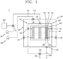
- FIG. 1 is a schematic view illustrating one embodiment of a fuel cell according to the present invention.
- a fuel cell 1 may be constituted as a direct methanol type fuel cell that generates electrical energy by direct reaction between methanol and oxygen, or a direct oxide type fuel cell in which a liquid or gaseous fuel containing hydrogen, such as ethanol, LPG, LNG, gasoline, butane gas and the like, reacts with oxygen.
- the fuel cell may be constituted as a polymer electrolyte fuel cell in which a fuel is reformed into gas containing hydrogen for use, or constituted as a phosphoric acid fuel cell, an alkaline fuel cell, a molten carbonate fuel cell, or a solid oxide fuel cell.
- the fuel used in the fuel cell 1 is referred to as a hydrocarbon-based fuel such as methanol, ethanol, natural gas, LPG or the like, which is in a liquid or gaseous state.
- the fuel cell 1 may include a fuel cell stack 100 that generates power using fuel and air, a fuel supply unit 200 that supplies the fuel to the fuel cell stack 100, and an air supply unit 300 that supplies the air into the fuel cell stack 100.
- the fuel cell stack 100 may be constituted only by one unit cell, but may generally be constituted by stacking a plurality of unit cells in a row.
- the unit cell may include an electrolyte membrane (membrane electrode assembly (MEA)) 101, a first separator (hereinafter, referred to as a fuel electrode for the sake of explanation) 102 disposed on one side of the electrolyte membrane 101 to form a fuel electrode, and a second separator 103 (hereinafter, referred to as an air electrode for the sake of explanation) disposed on an opposite side of the fuel electrode with the electrolyte membrane 101 interposed therebetween to form an air electrode.
- MEA electrolyte membrane
- a first separator hereinafter, referred to as a fuel electrode for the sake of explanation
- a second separator 103 hereinafter, referred to as an air electrode for the sake of explanation
- the fuel inlet/outlet ports communicate with the fuel flow path without communicating with the air flow path, while the air inlet/outflow ports communicate with the air flow path without communicating with the fuel flow path.
- the separator will be described by defining the fuel flow path side as the fuel electrode and the air flow path side as the air electrode.
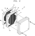
- FIG. 2 is a disassembled perspective view illustrating a fuel cell stack including unit cells in accordance with the present invention.
- a fuel electrode 102 may have a first fuel inlet/outlet port 121a and a second fuel inlet/outlet port 121b, which may serve as a fuel inlet or a fuel outlet depending on a direction in which the fuel is supplied.
- the first fuel inlet/outlet port 121a and the second fuel inlet/outlet port 121b communicate with both ends of a fuel flow path 122, respectively.
- the fuel flow path 122 may be formed in a zigzag shape or in a shape of a plurality of parallel flow paths so that the fuel can be widely diffused into the electrolyte membrane 101.
- the zigzag shape or the plural-flow path shape of the fuel flow path 122 may have a narrow cross-sectional area.
- a first fuel feeder 105 may be connected to the first fuel inlet/outlet port 121a and a second fuel feeder 106 may be connected to the second fuel inlet/outlet port 121b to control the fuel supply direction, respectively.
- the first fuel feeder 105 and the second fuel feeder 106 are configured to have the fuel supply directions opposite to each other.
- the first fuel feeder 105 supplies the fuel from the first fuel inlet/outlet port 121a to the second fuel inlet/outlet port 121b
- the second fuel feeder 107 supplies the fuel from the second fuel inlet/outlet port 121b to the first fuel inlet/outlet port 121a.
- the first fuel feeder 105 and the second fuel feeder 106 may be configured to form completely independent flow paths.
- the first fuel feeder 105 and the second fuel feeder 106 may preferably be configured to share a partial section, in view of reducing a number of components.
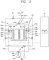
- FIG. 3 is a schematic view illustrating a fuel feeder for switching a fuel supply direction, in the fuel cell stack according to FIG. 1 .
- first fuel inlet/outlet pipe 123a may be connected to the first fuel inlet/outlet port 121a
- second fuel inlet/outlet pipe 123b may be connected to the second fuel inlet/outlet port 121b.
- a first fuel switching valve 124 may be disposed at another end of the first fuel inlet/outlet pipe 123a, and a first fuel supply pipe 126a and a second fuel discharge pipe 127b may be connected to the first fuel switching valve 124, respectively.
- the first fuel switching valve 124 may be configured as a three-way valve so that the first fuel inlet/outlet pipe 123a is connected to a first switching hole 124a, the first fuel supply pipe 126a is connected to a second switching hole 124b, and the second fuel discharge pipe 127b is connected to a third switching hole 124c.
- a second fuel switching valve 125 may be provided at another end of the second fuel inlet/outlet pipe 123b, and a second fuel supply pipe 126b and a first fuel discharge pipe 127a may be connected to the second fuel switching valve 125, respectively.
- the second fuel switching valve 125 may be configured as a three-way valve so that the second fuel inlet/outlet pipe 123b is connected to a first switching hole 125a, the second fuel supply pipe 126b is connected to a second switching hole 125b, and the first fuel discharge pipe 127a is connected to a third switching hole 125c.
- a fuel supply valve 128 may be provided between the first fuel supply pipe 126a and the second fuel supply pipe 126b, and a fuel discharge valve 129 may be provided between the first fuel discharge pipe 127a and the second fuel discharge pipe 127b.
- the fuel supply valve 128 may be configured as a three-way valve so that a first supply hole 128a thereof is connected to a fuel supply line 210 and the first fuel supply pipe 126a is connected to a second supply hole 128b, and the second fuel supply pipe 126b is connected to a third supply hole 128c.
- the fuel discharge valve 129 may be configured as a three-way valve so that a first discharge hole 129a is connected to a fuel discharge line 220, the first fuel discharge pipe 127a is connected to a second discharge hole 129b, and the second fuel discharge pipe 127b is connected to a third discharge hole 129c, respectively.
- the fuel supply valve 128, the fuel discharge valve 129, the first fuel switching valve 124 and the second fuel switching valve 125 may all be electrically connected to a controller 10, and accordingly, switching directions of those valves may be controlled by the controller 10.
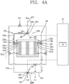
- the controller 10 controls the fuel supply valve 128 to communicate the first supply hole 128a with the second supply hole 128b, controls the first fuel switching valve 124 to communicate the second switching hole 124b with the first switching hole 124a, controls the second fuel switching valve 125 to communicate the first switching hole 125a with the third switching hole 125c, and the fuel discharge valve 129 to communicate the second discharge hole 129b with the first discharge hole 129a.
- the fuel flows from a fuel supply unit 200 into the first fuel inlet/outlet port 121a via the first fuel supply pipe 126a and the first fuel inlet/outlet pipe 123a along arrows in FIG. 4A .
- the fuel then moves toward the second fuel inlet/outlet port 121b along the fuel flow path 122 of the stack 100.
- the fuel is accordingly discharged into the fuel discharge line 220 via the second fuel inlet/outlet pipe 123b and the first fuel discharge pipe 127a. This series of processes is repeatedly executed.
- a temperature of the stack 100 may be detected by a temperature sensor 20 provided in the fuel cell stack 100.
- the controller 10 may switch the fuel supply direction.
- the controller 10 determines that the flow path is narrowed due to accumulation of impurities in the fuel flow path 122. Accordingly, the controller 10 switches an opening/closing direction of each valve, to switch the fuel supply direction into a direction of the second fuel feeder 106 as illustrated in FIG. 4B .
- the fuel is supplied in a direction opposite to that of FIG. 4A and moves along arrows in FIG. 4B .
- the impurities accumulated near the second fuel inlet/outlet port 121b of the fuel flow path 122 are pushed by the fuel introduced into the second fuel inlet/outlet port 121b.
- the impurities then flow toward the first fuel inlet/outlet port 121a.
- the impurities are removed from the fuel flow path 122 or at least do not block the fuel flow path 122. This may mitigate a local increase in the temperature near the second fuel inlet/outlet port 121b of the stack 100, thereby preventing a reduction of a lifetime of the stack or degradation of performance of the stack.
- the controller 10 may control the fuel supply direction by controlling an opening direction of each valve based on the temperature of the stack 100 detected by the temperature sensor 20, but, in some cases, may control the fuel supply direction to be periodically switched by using a timer 30 provided in the controller 10.
- the fuel cell according to this embodiment may further include an additional cooling device depending on an operating manner thereof.
- the temperature of the stack may be kept constant by using a separate cooling device without changing an air flow direction.
- the cooling device 40 may continuously supply cooling water to a housing surrounding the stack 100 to constantly maintain the temperature of the stack 100.
- the fuel cell stack 100 applied to the high power operation may be provided with a purge device 50 for removing impurities by supplying purge gas to the fuel flow path 122 of the stack.
- the fuel flow path 122 may be maintained in a relatively clean state at all times, and thus local overheating due to impurities can be prevented.
- a non-explained reference numeral 51 denotes a purge switching valve.
- an air supply unit for the air electrode 103 of the fuel cell may be configured similar to the fuel supply unit of the fuel electrode 102.
- FIG. 5 is a schematic view illustrating an air feeder for switching an air supply direction in the fuel cell stack according to FIG. 1 .
- a first air feeder 107 may be connected to a first air inlet/outlet port 131a and a second feeder 108 may be connected to a second air inlet/outlet port 131b, respectively, so as to control an air supply direction.
- the first air feeder 107 and the second air feeder 108 may be configured to have air supply directions opposite to each other.
- the first air feeder 107 supplies air from the first air inlet/outlet port 131a to the second air inlet/outlet port 131b
- the second air feeder 107 supplies air from the second air inlet/outlet port 131b to the first air inlet/outlet port 131a.
- the first air feeder 107 and the second air feeder 108 may form completely independent flow paths of each other.
- the first air feeder 107 and the second air feeder 108 may preferably be configured to share a partial section with each other so as to reduce a number of components.
- first air inlet/outlet port 131a and the second air inlet/outlet port 131b are provided one by one, one end of a first air inlet/outlet pipe 133a may be connected to the first air inlet/outlet port 131a, and one end of the second air inlet/outlet pipe 133b may be connected to the second air inlet/outlet port 131b.
- a first air switching valve 134 may be provided at another end of the first air inlet/outlet pipe 133a and a first air supply pipe 136a and a second air discharge pipe 137b may be connected to the first air switching valve 134, respectively.
- a first air switching valve 134 may be configured as a three-way valve so that the first air inlet/outlet pipe 133a is connected to a first switching hole 134a, the first air supply pipe 136a is connected to a second switching hole 134b, and the second air discharge pipe 137b is connected to a third switching hole 134c.
- a second air switching valve 135 may be provided at another end of the second air inlet/outlet pipe 133b.
- a second air supply pipe 133b and a first air discharge pipe 137a may be connected to the second air switching valve 135.
- the second air switching valve 135 may be configured as a three-way valve so that the second air inlet/outlet pipe 133b is connected to a first switching hole 135a, a second air supply pipe 136b is connected to a second switching hole 135b, and the first air discharge pipe 137a is connected to a third switching hole 135c.
- An air supply valve 138 may be provided between the first air supply pipe 136a and the second air supply pipe 136b and an air discharge valve 139 may be provided between the first air discharge pipe 137a and the second air discharge pipe 137b.
- the air supply valve 138 may be configured as a three-way valve so that an air supply line 310 is connected to a first supply hole 138a, the first air supply pipe 136a is connected to a second supply hole 138b, and the second air supply pipe 136b is connected to a third supply hole 138b.
- the air discharge valve 139 may be configured as a three-way valve so that an air discharge line 320 is connected to a first discharge hole 139a, the first air discharge pipe 137a is connected to the second discharge hole 139b, and the second air discharge pipe 137b is connected to a third discharge hole 139c.
- the air supply valve 138, the air discharge valve 139, the first air switching valve 134 and the second air switching valve 135 may all be electrically connected to the controller 10, and opening and closing directions of those valves may be controlled by the controller 10.
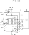
- the controller 10 controls the air supply valve 138 to communicate the first supply hole 138a with the second supply hole 138b, controls the second air switching valve 135 to communicate the first switching hole 135a with the third switching hole 135c, and controls the air discharge valve 139 to communicate the second discharge hole 139b with the first discharge hole 139a.
- the air flows from an air supply unit 300 into the first air inlet/outlet port 131a via the first air supply pipe 136a and the first air inlet/outlet pipe 133a along arrows in FIG. 6A .
- the air is then directed to the second air inlet/outlet port 131b along the air flow path 132 of the stack 100.
- the air is then discharged into the air discharge line 320 via the second air inlet/outlet pipe 133b and the first air discharge pipe 137a. This series of processes is repeatedly carried out.
- a temperature of the stack may be detected by a temperature sensor provided in the fuel cell stack according to this embodiment.
- the controller may switch the air supply direction.
- the controller switches the opening/closing direction of each valve to switch the air supply direction toward the second air feeder as illustrated in FIG. 6A .
- the air is supplied in a direction opposite to that of FIG. 6A and moves along the arrows in FIG. 6B .
- This may mitigate a local temperature increase of the stack, thereby preventing a reduction of a lifetime of the stack or degradation of performance of the stack.
- the controller 10 may control the opening direction of each valve based on the temperature of the stack 100 detected by the temperature sensor 20 to switch the air supply direction. However, in some cases, the controller 10 may control the air supply direction to be switched periodically using the timer 30 provided in the controller 10.
- the fuel supply direction is switched or the air supply direction is switched to prevent the stack from being locally overheated.
- the supply directions of the fuel and the air are simultaneously switched so as to remove impurities accumulated in the stack and simultaneously cool the stack down to a proper temperature.
- the flow directions of the fuel and the air can be adjusted to a forward or reverse direction as needed, thereby effectively coping with the local overheating phenomenon in the stack.
- the fuel supply direction may be switched every time of being overheated by using the temperature sensor 20 or periodically switched using the timer 30 to remove the impurities accumulated in the vicinity of the second fuel inlet/outlet port 121b, thereby enhancing the performance of the fuel cell stack.
- a temperature of the stack is detected using a temperature sensor or a switching time point is detected using a timer (S12).
- a fuel supply direction may be switched while maintaining an air supply direction (S13).
- the stack since the stack is not overheated excessively due to a large number of rated power operations, the stack can be maintained at a constant temperature by using a cooling device provided to enclose the stack 100.
- the fuel does not have to be supplied in a crossing manner.
- the high power operation is more demanded than the rated power operation and accordingly a temperature difference between the unit cells constituting the stack 100 may more increase. Therefore, in this instance, the temperature difference between the unit cells can be reduced by periodically switching the air supply direction or switching the air supply direction every time of turning on or off the fuel cell, thereby enhancing performance of the stack.
- the purge control is performed (S21), and it is determined using the timer whether or not the switching is necessary (S22).
- the air supply direction may be switched periodically or every time of turning on or off the fuel cell (S23).
- the performance of the stack can be further improved by changing both the fuel supply direction and the air supply direction periodically or every time of turning on or off the fuel cell.
- the temperature difference between the unit cells is detected using the temperature sensor 20 (S31).
- the fuel feeder and the air feeder may be controlled to switch all of the fuel and air supply directions (S32).
- the fuel cell according to the present invention can switch the supply directions of the fuel and the air according to a variation of a load applied to the stack.
- a load variation detector such as a wattmeter provided in a system of the fuel cell may be used to measure a load amount required for the fuel cell. Accordingly, it may be determined whether the flow directions of the fuel and the air should be switched. When the switching is necessary according to the determination, the supply directions of the fuel and the air may be switched.
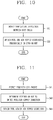
- the detected load amount may be checked (S41), and it may be determined whether to switch the supply direction of the fuel or air or the supply directions of the fuel and the air (S42). According to the determination, the supply directions of the fuel and the air can be switched by adjusting various valves, thereby enhancing the performance of the stack.
- the performance of the stack may be lowered due to collision between fluids. Therefore, as illustrated in FIG. 12 , it may be determined whether to switch the supply directions of the fuel and the air before the switching is carried out (S51). If necessary, various sensors provided in the vehicle may be used to determine whether the vehicle is in a driving state or in a stopped state (S52). When the vehicle is in the stopped state, the flow directions of the fuel and the air can be switched (S53). Thus, the performance of the fuel cell can be enhanced by preventing the collision between the fluids due to the switching of the supply directions of the fuel or the air during the travel of the vehicle.
- the fuel cell according to the present invention when applied to a stationary type such as a generator, it is usually operated for a long time. Therefore, preferably, the fuel and air flow directions may not be switched while the generator is operating, and may be switched when the operation of the generator is stopped, which may result in preventing in advance deterioration of the performance of the fuel cell due to the collision between the fluids.
Landscapes
- Life Sciences & Earth Sciences (AREA)
- Engineering & Computer Science (AREA)
- Manufacturing & Machinery (AREA)
- Sustainable Development (AREA)
- Sustainable Energy (AREA)
- Chemical & Material Sciences (AREA)
- Chemical Kinetics & Catalysis (AREA)
- Electrochemistry (AREA)
- General Chemical & Material Sciences (AREA)
- Fuel Cell (AREA)
Abstract
Description
- This specification relates to a fuel cell, and more particularly, a fuel cell capable of switching supply directions of fuel and air supplied to a stack, and a method for operating the same.
- Generally, fuel cells are under development to replace existing fossil fuels with eco-friendly energy. Fuel cells, such as home fuel cells for supplying electric power to home, fuel cells for electric vehicles, fuel cells for portable terminals and notebook computers, and fuel cells for supplying electric power in a portable manner at home, are being studied and developed in various application fields.
- Fuel cells are classified, according to a type of electrolyte, into phosphoric acid fuel cell (PAFC), alkaline fuel cell (AFC), proton exchange membrane fuel cell (PEMFC), molten carbonate fuel cell (MCFC), solid oxide fuel cell (SOFC), direct methanol fuel cell (DMFC), direct borohydride fuel cell (DMFC) and the like.
- It is known that operating temperatures of these fuel cells are about 200°C for the phosphoric acid type, 60-110°C for the alkali type, room temperature to 80°C for the polymer electrolyte type, 500 to 700°C for the molten carbonate electrolyte type, high temperature over 1000°C for the solid oxide type and 25 to 130°C for the direct methanol type.
- Unlike typical batteries (secondary batteries), the fuel cell supplies fuel (hydrogen gas or hydrocarbon) and oxygen to a fuel electrode (anode) and an air electrode (cathode), respectively, which form a stack, thereby arousing an electrochemical reaction between the hydrogen and the oxygen without a burning (oxidation) reaction. Then, an energy difference between before and after the electrochemical reaction is directly converted into electric energy.
- Meanwhile, the stack is formed by stacking a plurality of unit cells. Each unit cell includes a fuel electrode and an air electrode stacked with interposing an electrolyte membrane therebetween. Among others, the fuel electrode has a narrow and complicated flow path to evenly disperse the supplied fuel to its entire area. Accordingly, when the fuel cell operates for a long period of time, impurities may be accumulated in the flow path of the fuel electrode, and thereby the flow path may be blocked due to the impurities.
- Particularly, although the impurities are not greatly accumulated in an inlet side of the fuel electrode, more impurities may be accumulated toward an outlet side. Accordingly, a reaction area of fuel and air decreases at the outlet side of the fuel electrode, which causes lowering of energy efficiency.
- In view of this, it has been known that the related art fuel cell employs an operating method of executing a main operation after removing impurities by supplying purge gas periodically while a system is stopped or washing the fuel electrode by supplying nitrogen for a predetermined period of time upon starting the system. However, in this instance, since the system should be stopped for the predetermined period of time, an operation time is shortened and energy efficiency is lowered accordingly.
- In addition, as described above, the fuel cell generates heat while hydrogen and oxygen as the fuel react with each other, and the temperature at the outlet side of the flow path (air electrode) becomes the highest due to the heat generated during the reaction and a continuous flow of fluid. Accordingly, the temperature at the outlet side of the air electrode is locally increased, which may cause the electrolyte membranes of some of the unit cells to be broken. If the electrolyte membrane is broken, the unit cell should be replaced or, in severe cases, the use of the entire stack is restricted. This causes lowering of the energy efficiency. Typically, the fuel cell is provided with an air-cooling or water-cooling type cooling device, but the related art cooling device cools the entire stack. However, the related art cooling device is not suitable for cooling a locally heated portion and even the cooling operation is carried out for a non-heated portion. As a result, the stack cannot be maintained at a proper temperature and the operation efficiency is lowered.
- Therefore, an aspect of the detailed description is to provide a fuel cell capable of removing impurities accumulated in a stack even without stopping an operation.
- Another aspect of the detailed description is to provide a fuel cell capable of producing electricity even during a process of removing impurities.
- Another aspect of the detailed description is to provide a fuel cell capable of increasing efficiency thereof by removing impurities in a manner of checking in real time how much impurities have been accumulated.
- Another aspect of the detailed description is to provide a fuel cell capable of cooling a stack down to a proper temperature even without stopping an operation.
- Another aspect of the detailed description is to provide a fuel cell capable of locally cooling a stack.
- The objects are solved by the features of the independent claims. According to one embodiment, there is provided a fuel cell, e.g. for supplying a hydrocarbon-based fuel, which is capable of preventing an accumulation of impurities in a stack by switching a supply direction of the fuel from an inlet to an outlet or from the outlet to the inlet.
- Here, a pipe for supplying or discharging the fuel may be connected to an inlet and an outlet of the stack in a closed loop shape, and a switching valve for controlling a fuel supply direction and a fuel discharge direction may be installed in a middle of the pipe.
- And, an air supply unit for supplying air in the stack may be provided, and configured to switch an air supply direction under control of the controller.
- According to a further example, there is provided a fuel cell, including a stack provided with an electrolyte membrane, a fuel electrode disposed on one side of the electrolyte membrane, and having a first fuel inlet/outlet port and a second fuel inlet/outlet port that communicate with each other via a fuel flow path, and an air electrode disposed on an opposite side to the fuel electrode with the electrolyte membrane interposed therebetween, and having a first air inlet/outlet port and a second air inlet/outlet port that communicate with each other via an air flow path, and at least one of a fuel switching unit configured to switch a fuel supply direction from the first fuel inlet/outlet port to the second fuel inlet/outlet port or reversely from the second fuel inlet/outlet port to the first fuel inlet/outlet port, and an air switching unit configured to switch an air supply direction from the first air inlet/outlet port to the second air inlet/outlet port or reversely from the second air inlet/outlet port to the first air inlet/outlet port.
- Preferably, the fuel cell includes further a first fuel feeder communicating with the first fuel inlet/outlet port, and a second fuel feeder communicating with the second fuel inlet/outlet port. Also, the fuel cell may include a first air feeder communicating with the first air inlet/outlet port, and a second air feeder communicating with the second air inlet/outlet port.Here, the fuel switching unit may be provided between the first fuel feeder and the second fuel feeder to switch a fuel supply direction to a direction from the first fuel feeder to the second fuel feeder or reversely to a direction from the second fuel feeder to the first fuel feeder. Alternatively or additionally, the air switching unit may be provided between the first air feeder and the second air feeder to switch an air supply direction to a direction from the first air feeder to the second air feeder or reversely to a direction from the second air feeder to the first air feeder.
- Here, the first fuel feeder and the second fuel feeder may share at least part of a flow path. The fuel switching unit may be located on the flow path shared by the first fuel feeder and the second fuel feeder.
- The first fuel inlet/outlet port of the stack may be connected to one end of a first fuel inlet/outlet pipe. The second fuel inlet/outlet port of the stack may be connected to one end of a second fuel inlet/outlet pipe. Preferably, a first fuel switching valve may be provided on another end of the first fuel inlet/outlet pipe. Preferably, a first fuel supply pipe and a second fuel discharge pipe may be connected to the first fuel switching valve. Preferably, a second fuel switching valve may be provided on another end of the second fuel inlet/outlet pipe.A second fuel supply pipe and a first fuel discharge pipe may be connected to the second fuel switching valve.
- The first fuel supply pipe and the second fuel supply pipe may be connected to a fuel supply valve for deciding a fuel supply direction. The first fuel discharge pipe and the second fuel discharge pipe may be connected to a fuel discharge valve for deciding a fuel discharge direction.The fuel supply valve and the fuel discharge valve may be controlled to be cooperatively open and closed.
- The first air feeder and the second air feeder may share at least part of a flow path.The air switching unit may be located on the path shared by the first air feeder and the second air feeder.
- The first air inlet/outlet port of the stack may be connected to one end of a first air inlet/outlet pipe. The second air inlet/outlet port of the stack may be connected to one end of a second air inlet/outlet pipe. A first air switching valve may be provided on another end of the first air inlet/outlet pipe. A first air supply pipe and a second air discharge pipe may be connected to the first air switching valve. A second air switching valve may be provided on another end of the second air inlet/outlet pipe.A second air supply pipe and a first air discharge pipe may be connected to the second air switching valve.
- The first air supply pipe and the second air supply pipe may be connected to an air supply valve for deciding an air supply direction. The first air discharge pipe and the second air discharge pipe may be connected to an air discharge valve for deciding an air discharge direction. The air supply valve and the air discharge valve may be controlled to be cooperatively open and closed.
- The stack may be provided with a cooling unit at an outside thereof. The cooling unit may be controlled to cooperate with the fuel switching unit and/or the air switching unit.
- In accordance with another embodiment of the present invention, a fuel cell may include a stack provided with a fuel electrode having a first fuel inlet/outlet port and a second fuel inlet/outlet port, and an air electrode having a first air inlet/outlet port and a second air inlet/outlet port, a first fuel/air feeder connected to the first fuel inlet/outlet port and the first air inlet/outlet port, a second fuel/air feeder connected to the second fuel inlet/outlet port and the second air inlet/outlet port, and a controller electrically connected to the first fuel/air feeder and the second fuel/air feeder to switch the fuel/air supply direction to a direction toward the first fuel/air feeder or the second fuel/air feeder.
- Here, the fuel cell may further include a load variation detecting unit configured to detect a variation of a load applied to the stack. The load variation detecting unit may be electrically connected to the controller to cooperate with the fuel switching unit and/or the air switching unit.
- The fuel cell may further include a temperature detecting unit configured to detect heat generated from the stack. The temperature detecting unit may be electrically connected to the controller to cooperate with the fuel switching unit or the air switching unit.
- The fuel cell may further include a timer configured to calculate a time for which the fuel or air is supplied from the fuel switching unit or the air switching unit in a corresponding direction. The timer may be electrically connected to the controller to cooperate with the fuel switching unit or the air switching unit.
- According to another embodiment, there is provided a method for operating a fuel cell, the method including supplying fuel and air in a first direction into a fuel flow path and an air flow path provided within a stack, and supplying at least one of the fuel and the air supplied in the first direction into a second direction opposite to the first direction.
- Here, the method may further include determining whether or not it is necessary to switch the fuel supply direction and the air supply direction within the stack before switching the fuel supply direction and the air supply direction.
- The fuel supply direction and the air supply direction into the stack may be decided by detecting a variation of a load applied to the stack or a stack temperature.
- The fuel supply direction and the air supply direction are periodically decided by accumulating a duration for the fuel and the air supply directions in the stack.
- In the fuel cell and the method of operating the same according to the present invention, the flow directions of the fuel and the air can be switched so that impurities accumulated in the stack can be removed without stopping an operation and energy can be generated even during the removal of the impurities, thereby enhancing energy efficiency of the fuel cell.
- Also, the efficiency of the fuel cell can be further improved by removing impurities while checking in real time whether the impurities are accumulated by employing a temperature sensor, a timer or a wattmeter.
- In addition, as the air supply direction is switched as needed, the stack can be cooled to an appropriate temperature or locally cooled without stopping the operation, thereby improving performance of the stack.
- Further scope of applicability of the present application will become more apparent from the detailed description given hereinafter. However, it should be understood that the detailed description and specific examples, while indicating preferred embodiments of the invention, are given by way of illustration only, since various changes and modifications within the scope of the invention will become apparent to those skilled in the art from the detailed description.
- The accompanying drawings, which are included to provide a further understanding of the invention and are incorporated in and constitute a part of this specification, illustrate exemplary embodiments and together with the description serve to explain the principles of the invention.
- In the drawings:
-
FIG. 1 is a schematic view illustrating one embodiment of a fuel cell according to the present invention; -
FIG. 2 is a disassembled perspective view illustrating a fuel cell stack including unit cells in accordance with the present invention; -
FIG. 3 is a schematic view illustrating a fuel feeder for switching a supply direction of a fuel, in the fuel cell stack according toFIG. 1 ; -
FIGS. 4A and4B are schematic views illustrating embodiments of the supply direction of the fuel in the fuel feeder of the stack according toFIG. 3 ; -
FIG. 5 is a schematic view illustrating an air feeder for switching a supply direction of air in the fuel cell stack according toFIG. 1 ; -
FIGS. 6A and6B are schematic views illustrating embodiments of the supply direction of the air in the air feeder of the stack according toFIG. 5 ; -
FIG. 7 is a schematic view illustrating the fuel feeder and the air feeder for switching the supply directions of the fuel and the air in the fuel cell stack according toFIG. 1 ; and -
FIGS. 8 to 12 are block diagrams illustrating processes of switching the supply directions of the fuel and the air, respectively, in the fuel cell stack according toFIG. 1 . - Description will now be given of a fuel cell and a method for operating the same according to exemplary embodiments disclosed herein, with reference to the accompanying drawings. However, the present invention may be implemented into various forms and may not be limited to the embodiments disclosed herein.
-
FIG. 1 is a schematic view illustrating one embodiment of a fuel cell according to the present invention. - As illustrated in
FIG. 1 , afuel cell 1 according to an embodiment of the present invention may be constituted as a direct methanol type fuel cell that generates electrical energy by direct reaction between methanol and oxygen, or a direct oxide type fuel cell in which a liquid or gaseous fuel containing hydrogen, such as ethanol, LPG, LNG, gasoline, butane gas and the like, reacts with oxygen. Also, the fuel cell may be constituted as a polymer electrolyte fuel cell in which a fuel is reformed into gas containing hydrogen for use, or constituted as a phosphoric acid fuel cell, an alkaline fuel cell, a molten carbonate fuel cell, or a solid oxide fuel cell. - The fuel used in the
fuel cell 1 is referred to as a hydrocarbon-based fuel such as methanol, ethanol, natural gas, LPG or the like, which is in a liquid or gaseous state. - The
fuel cell 1 according to the embodiment may include afuel cell stack 100 that generates power using fuel and air, afuel supply unit 200 that supplies the fuel to thefuel cell stack 100, and anair supply unit 300 that supplies the air into thefuel cell stack 100. - The
fuel cell stack 100 may be constituted only by one unit cell, but may generally be constituted by stacking a plurality of unit cells in a row. - The unit cell may include an electrolyte membrane (membrane electrode assembly (MEA)) 101, a first separator (hereinafter, referred to as a fuel electrode for the sake of explanation) 102 disposed on one side of the
electrolyte membrane 101 to form a fuel electrode, and a second separator 103 (hereinafter, referred to as an air electrode for the sake of explanation) disposed on an opposite side of the fuel electrode with theelectrolyte membrane 101 interposed therebetween to form an air electrode. That is, one separator is provided with a fuel flow path to be explained later on one side thereof and an air flow path to be explained later on another side thereof, and fuel inlet/outlet ports and air inlet/outlet ports are independently formed at positions without communicating with each other. Accordingly, the fuel inlet/outlet ports communicate with the fuel flow path without communicating with the air flow path, while the air inlet/outflow ports communicate with the air flow path without communicating with the fuel flow path. Hereinafter, for the sake of explanation, the separator will be described by defining the fuel flow path side as the fuel electrode and the air flow path side as the air electrode. -
FIG. 2 is a disassembled perspective view illustrating a fuel cell stack including unit cells in accordance with the present invention. - As illustrated in
FIGS. 1 and2 , afuel electrode 102 may have a first fuel inlet/outlet port 121a and a second fuel inlet/outlet port 121b, which may serve as a fuel inlet or a fuel outlet depending on a direction in which the fuel is supplied. The first fuel inlet/outlet port 121a and the second fuel inlet/outlet port 121b communicate with both ends of afuel flow path 122, respectively. Thefuel flow path 122 may be formed in a zigzag shape or in a shape of a plurality of parallel flow paths so that the fuel can be widely diffused into theelectrolyte membrane 101. The zigzag shape or the plural-flow path shape of thefuel flow path 122 may have a narrow cross-sectional area. - Here, a
first fuel feeder 105 may be connected to the first fuel inlet/outlet port 121a and asecond fuel feeder 106 may be connected to the second fuel inlet/outlet port 121b to control the fuel supply direction, respectively. - The
first fuel feeder 105 and thesecond fuel feeder 106 are configured to have the fuel supply directions opposite to each other. For example, thefirst fuel feeder 105 supplies the fuel from the first fuel inlet/outlet port 121a to the second fuel inlet/outlet port 121b, while thesecond fuel feeder 107 supplies the fuel from the second fuel inlet/outlet port 121b to the first fuel inlet/outlet port 121a. - For this purpose, when a number of the first fuel inlet/
outlet port 121a and a number of the second fuel inlet/outlet port 121b are two, respectively, thefirst fuel feeder 105 and thesecond fuel feeder 106 may be configured to form completely independent flow paths. As illustrated inFIG. 3 , when the first fuel inlet/outlet port 121a and the second fuel inlet/outlet port 121b are provided one by one, thefirst fuel feeder 105 and thesecond fuel feeder 106 may preferably be configured to share a partial section, in view of reducing a number of components. -
FIG. 3 is a schematic view illustrating a fuel feeder for switching a fuel supply direction, in the fuel cell stack according toFIG. 1 . - As illustrated in
FIG. 3 , when the fuel cell according this embodiment is provided with the first fuel inlet/outlet port 121a and the second fuel inlet/outlet port 121b one by one, one end of a first fuel inlet/outlet pipe 123a may be connected to the first fuel inlet/outlet port 121a, and one end of a second fuel inlet/outlet pipe 123b may be connected to the second fuel inlet/outlet port 121b. - A first
fuel switching valve 124 may be disposed at another end of the first fuel inlet/outlet pipe 123a, and a firstfuel supply pipe 126a and a secondfuel discharge pipe 127b may be connected to the firstfuel switching valve 124, respectively. - The first
fuel switching valve 124 may be configured as a three-way valve so that the first fuel inlet/outlet pipe 123a is connected to afirst switching hole 124a, the firstfuel supply pipe 126a is connected to asecond switching hole 124b, and the secondfuel discharge pipe 127b is connected to athird switching hole 124c. - A second
fuel switching valve 125 may be provided at another end of the second fuel inlet/outlet pipe 123b, and a secondfuel supply pipe 126b and a firstfuel discharge pipe 127a may be connected to the secondfuel switching valve 125, respectively. - The second
fuel switching valve 125 may be configured as a three-way valve so that the second fuel inlet/outlet pipe 123b is connected to afirst switching hole 125a, the secondfuel supply pipe 126b is connected to asecond switching hole 125b, and the firstfuel discharge pipe 127a is connected to athird switching hole 125c. - On the other hand, a
fuel supply valve 128 may be provided between the firstfuel supply pipe 126a and the secondfuel supply pipe 126b, and afuel discharge valve 129 may be provided between the firstfuel discharge pipe 127a and the secondfuel discharge pipe 127b. - The
fuel supply valve 128 may be configured as a three-way valve so that afirst supply hole 128a thereof is connected to afuel supply line 210 and the firstfuel supply pipe 126a is connected to asecond supply hole 128b, and the secondfuel supply pipe 126b is connected to athird supply hole 128c. - The
fuel discharge valve 129 may be configured as a three-way valve so that afirst discharge hole 129a is connected to afuel discharge line 220, the firstfuel discharge pipe 127a is connected to asecond discharge hole 129b, and the secondfuel discharge pipe 127b is connected to athird discharge hole 129c, respectively. - Meanwhile, the
fuel supply valve 128, thefuel discharge valve 129, the firstfuel switching valve 124 and the secondfuel switching valve 125 according to this embodiment may all be electrically connected to acontroller 10, and accordingly, switching directions of those valves may be controlled by thecontroller 10. - That is, when a fuel (hydrogen) is supplied in a direction of the
first fuel feeder 105, thecontroller 10 controls thefuel supply valve 128 to communicate thefirst supply hole 128a with thesecond supply hole 128b, controls the firstfuel switching valve 124 to communicate thesecond switching hole 124b with thefirst switching hole 124a, controls the secondfuel switching valve 125 to communicate thefirst switching hole 125a with thethird switching hole 125c, and thefuel discharge valve 129 to communicate thesecond discharge hole 129b with thefirst discharge hole 129a. - Accordingly, the fuel flows from a
fuel supply unit 200 into the first fuel inlet/outlet port 121a via the firstfuel supply pipe 126a and the first fuel inlet/outlet pipe 123a along arrows inFIG. 4A . The fuel then moves toward the second fuel inlet/outlet port 121b along thefuel flow path 122 of thestack 100. The fuel is accordingly discharged into thefuel discharge line 220 via the second fuel inlet/outlet pipe 123b and the firstfuel discharge pipe 127a. This series of processes is repeatedly executed. - However, a temperature of the
stack 100 may be detected by atemperature sensor 20 provided in thefuel cell stack 100. When the detected value increases over a preset value, thecontroller 10 may switch the fuel supply direction. - That is, when the temperature of the stack detected by the
temperature sensor 20 rises above the preset temperature, thecontroller 10 determines that the flow path is narrowed due to accumulation of impurities in thefuel flow path 122. Accordingly, thecontroller 10 switches an opening/closing direction of each valve, to switch the fuel supply direction into a direction of thesecond fuel feeder 106 as illustrated inFIG. 4B . - Accordingly, the fuel is supplied in a direction opposite to that of
FIG. 4A and moves along arrows inFIG. 4B . Thus, the impurities accumulated near the second fuel inlet/outlet port 121b of thefuel flow path 122 are pushed by the fuel introduced into the second fuel inlet/outlet port 121b. The impurities then flow toward the first fuel inlet/outlet port 121a. During the flow, the impurities are removed from thefuel flow path 122 or at least do not block thefuel flow path 122. This may mitigate a local increase in the temperature near the second fuel inlet/outlet port 121b of thestack 100, thereby preventing a reduction of a lifetime of the stack or degradation of performance of the stack. - Here, the
controller 10, as aforementioned, may control the fuel supply direction by controlling an opening direction of each valve based on the temperature of thestack 100 detected by thetemperature sensor 20, but, in some cases, may control the fuel supply direction to be periodically switched by using atimer 30 provided in thecontroller 10. - Further, the fuel cell according to this embodiment may further include an additional cooling device depending on an operating manner thereof.
- For example, when a rated output operation is more demanded than a high power operation, the temperature of the stack may be kept constant by using a separate cooling device without changing an air flow direction. As illustrated in
FIG. 1 , thecooling device 40 may continuously supply cooling water to a housing surrounding thestack 100 to constantly maintain the temperature of thestack 100. - Here, the
fuel cell stack 100 applied to the high power operation may be provided with apurge device 50 for removing impurities by supplying purge gas to thefuel flow path 122 of the stack. In this instance, thefuel flow path 122 may be maintained in a relatively clean state at all times, and thus local overheating due to impurities can be prevented. However, since the temperature difference between the unit cells due to the high output operation is greater than that at the rated power operation, it may be preferable to supply air in an intersecting (crossing) manner using an air supply unit to be explained later. Anon-explained reference numeral 51 denotes a purge switching valve. - Hereinafter, another embodiment of a fuel cell according to the present invention will be described.
- That is, in the above-described embodiment, the supply direction of the fuel is changed to prevent the local overheating of the stack. However, in this embodiment, the stack is cooled to be maintained at a proper temperature by switching an air supply direction with maintaining the fuel supply direction in one direction. As illustrated in
FIG. 5 , an air supply unit for theair electrode 103 of the fuel cell according to this embodiment may be configured similar to the fuel supply unit of thefuel electrode 102. -
FIG. 5 is a schematic view illustrating an air feeder for switching an air supply direction in the fuel cell stack according toFIG. 1 . - As illustrated in
FIG. 5 , afirst air feeder 107 may be connected to a first air inlet/outlet port 131a and asecond feeder 108 may be connected to a second air inlet/outlet port 131b, respectively, so as to control an air supply direction. - The
first air feeder 107 and thesecond air feeder 108 may be configured to have air supply directions opposite to each other. For example, thefirst air feeder 107 supplies air from the first air inlet/outlet port 131a to the second air inlet/outlet port 131b, while thesecond air feeder 107 supplies air from the second air inlet/outlet port 131b to the first air inlet/outlet port 131a. - For this purpose, when a number of the first air inlet/
outlet port 131 a and a number of the second air inlet/outlet port 131b are two, respectively, thefirst air feeder 107 and thesecond air feeder 108 may form completely independent flow paths of each other. On the other hand, as illustrated inFIG. 5 , when the first air inlet/outlet port 131a and the second air inlet/outlet port 131b are provided one by one, thefirst air feeder 107 and thesecond air feeder 108 may preferably be configured to share a partial section with each other so as to reduce a number of components. - When the first air inlet/
outlet port 131a and the second air inlet/outlet port 131b are provided one by one, one end of a first air inlet/outlet pipe 133a may be connected to the first air inlet/outlet port 131a, and one end of the second air inlet/outlet pipe 133b may be connected to the second air inlet/outlet port 131b. - A first
air switching valve 134 may be provided at another end of the first air inlet/outlet pipe 133a and a firstair supply pipe 136a and a secondair discharge pipe 137b may be connected to the firstair switching valve 134, respectively. - A first
air switching valve 134 may be configured as a three-way valve so that the first air inlet/outlet pipe 133a is connected to afirst switching hole 134a, the firstair supply pipe 136a is connected to asecond switching hole 134b, and the secondair discharge pipe 137b is connected to athird switching hole 134c. - A second
air switching valve 135 may be provided at another end of the second air inlet/outlet pipe 133b. A secondair supply pipe 133b and a firstair discharge pipe 137a may be connected to the secondair switching valve 135. - The second
air switching valve 135 may be configured as a three-way valve so that the second air inlet/outlet pipe 133b is connected to afirst switching hole 135a, a secondair supply pipe 136b is connected to asecond switching hole 135b, and the firstair discharge pipe 137a is connected to athird switching hole 135c. - An
air supply valve 138 may be provided between the firstair supply pipe 136a and the secondair supply pipe 136b and anair discharge valve 139 may be provided between the firstair discharge pipe 137a and the secondair discharge pipe 137b. - The
air supply valve 138 may be configured as a three-way valve so that anair supply line 310 is connected to afirst supply hole 138a, the firstair supply pipe 136a is connected to asecond supply hole 138b, and the secondair supply pipe 136b is connected to athird supply hole 138b. - The
air discharge valve 139 may be configured as a three-way valve so that anair discharge line 320 is connected to afirst discharge hole 139a, the firstair discharge pipe 137a is connected to thesecond discharge hole 139b, and the secondair discharge pipe 137b is connected to athird discharge hole 139c. - Meanwhile, the
air supply valve 138, theair discharge valve 139, the firstair switching valve 134 and the secondair switching valve 135 according to this embodiment may all be electrically connected to thecontroller 10, and opening and closing directions of those valves may be controlled by thecontroller 10. - That is, when the air is supplied in a direction of the
first air feeder 107, thecontroller 10 controls theair supply valve 138 to communicate thefirst supply hole 138a with thesecond supply hole 138b, controls the secondair switching valve 135 to communicate thefirst switching hole 135a with thethird switching hole 135c, and controls theair discharge valve 139 to communicate thesecond discharge hole 139b with thefirst discharge hole 139a. - Accordingly, the air flows from an
air supply unit 300 into the first air inlet/outlet port 131a via the firstair supply pipe 136a and the first air inlet/outlet pipe 133a along arrows inFIG. 6A . The air is then directed to the second air inlet/outlet port 131b along theair flow path 132 of thestack 100. The air is then discharged into theair discharge line 320 via the second air inlet/outlet pipe 133b and the firstair discharge pipe 137a. This series of processes is repeatedly carried out. - However, a temperature of the stack may be detected by a temperature sensor provided in the fuel cell stack according to this embodiment. When the detected value increases over a preset value, the controller may switch the air supply direction.
- That is, when the temperature of the stack detected by the temperature sensor rises above the preset temperature, the controller switches the opening/closing direction of each valve to switch the air supply direction toward the second air feeder as illustrated in
FIG. 6A . - Accordingly, the air is supplied in a direction opposite to that of
FIG. 6A and moves along the arrows inFIG. 6B . This may mitigate a local temperature increase of the stack, thereby preventing a reduction of a lifetime of the stack or degradation of performance of the stack. - As described above, the
controller 10 may control the opening direction of each valve based on the temperature of thestack 100 detected by thetemperature sensor 20 to switch the air supply direction. However, in some cases, thecontroller 10 may control the air supply direction to be switched periodically using thetimer 30 provided in thecontroller 10. - Hereinafter, still another embodiment of a fuel cell according to the present invention will be described.
- That is, in the above-described embodiments, the fuel supply direction is switched or the air supply direction is switched to prevent the stack from being locally overheated. However, in this embodiment, the supply directions of the fuel and the air are simultaneously switched so as to remove impurities accumulated in the stack and simultaneously cool the stack down to a proper temperature.
- Here, the
fuel feeder air feeder fuel electrode 102 and theair electrode 103, respectively, and the fuel switching parts (123a,123b), (124,124a,124b,124c), (125,125a,125b,125c) (126a,126b)(127a,127b), (128,128a,128b,128c), (129,129a,129b,129c) and the air switching parts (133a,133b) (134,134a,134b,134c) (135,135a,135b,135c) (136a,136b) (137a,137b) (138,138a,138b,138c) (139,139a,139b,139c) may be configured, as illustrated inFIG. 7 , by combining the foregoing embodiments. - The basic configuration and operation are similar to those of the foregoing two embodiments, so detailed description thereof will be omitted. However, according this embodiment, the flow directions of the fuel and the air can be adjusted to a forward or reverse direction as needed, thereby effectively coping with the local overheating phenomenon in the stack.
- For example, in case where a rated power operation is more required than a high power operation, when the flow direction of the air supplied to the
air electrode 103 is maintained in one direction but surroundings of the second fuel inlet/outlet port 121b of thefuel electrode 102 is locally overheated due to being blocked by accumulated impurities, the fuel supply direction may be switched every time of being overheated by using thetemperature sensor 20 or periodically switched using thetimer 30 to remove the impurities accumulated in the vicinity of the second fuel inlet/outlet port 121b, thereby enhancing the performance of the fuel cell stack. - To this end, as illustrated in
FIG. 8 , it is determined whether the power operation is a rated power operation (S11). Also, a temperature of the stack is detected using a temperature sensor or a switching time point is detected using a timer (S12). When the switching time point is detected, a fuel supply direction may be switched while maintaining an air supply direction (S13). - Thus, since the stack is not overheated excessively due to a large number of rated power operations, the stack can be maintained at a constant temperature by using a cooling device provided to enclose the
stack 100. - When impurities are not accumulated in the stack by virtue of high purity of the hydrogen fuel and a purge control, the fuel does not have to be supplied in a crossing manner. However, the high power operation is more demanded than the rated power operation and accordingly a temperature difference between the unit cells constituting the
stack 100 may more increase. Therefore, in this instance, the temperature difference between the unit cells can be reduced by periodically switching the air supply direction or switching the air supply direction every time of turning on or off the fuel cell, thereby enhancing performance of the stack. - For this, as illustrated in
FIG. 9 , the purge control is performed (S21), and it is determined using the timer whether or not the switching is necessary (S22). When the switching is necessary according to the determination, the air supply direction may be switched periodically or every time of turning on or off the fuel cell (S23). - On the other hand, when the temperature difference between the unit cells is great and impurities are much contained in the fuel, the performance of the stack can be further improved by changing both the fuel supply direction and the air supply direction periodically or every time of turning on or off the fuel cell.
- To this end, as illustrated in
FIG. 10 , the temperature difference between the unit cells is detected using the temperature sensor 20 (S31). When the temperature difference is greater than a preset value, the fuel feeder and the air feeder may be controlled to switch all of the fuel and air supply directions (S32). - Meanwhile, the fuel cell according to the present invention can switch the supply directions of the fuel and the air according to a variation of a load applied to the stack.
- For example, when the fuel cell according to the present invention is applied to a vehicle having a large load variation, a load variation detector (not illustrated) such as a wattmeter provided in a system of the fuel cell may be used to measure a load amount required for the fuel cell. Accordingly, it may be determined whether the flow directions of the fuel and the air should be switched. When the switching is necessary according to the determination, the supply directions of the fuel and the air may be switched.
- That is, the detected load amount may be checked (S41), and it may be determined whether to switch the supply direction of the fuel or air or the supply directions of the fuel and the air (S42). According to the determination, the supply directions of the fuel and the air can be switched by adjusting various valves, thereby enhancing the performance of the stack.
- In addition, when the flow directions of the fuel and the air are switched during a travel of the vehicle, the performance of the stack may be lowered due to collision between fluids. Therefore, as illustrated in
FIG. 12 , it may be determined whether to switch the supply directions of the fuel and the air before the switching is carried out (S51). If necessary, various sensors provided in the vehicle may be used to determine whether the vehicle is in a driving state or in a stopped state (S52). When the vehicle is in the stopped state, the flow directions of the fuel and the air can be switched (S53). Thus, the performance of the fuel cell can be enhanced by preventing the collision between the fluids due to the switching of the supply directions of the fuel or the air during the travel of the vehicle. - On the other hand, when the fuel cell according to the present invention is applied to a stationary type such as a generator, it is usually operated for a long time. Therefore, preferably, the fuel and air flow directions may not be switched while the generator is operating, and may be switched when the operation of the generator is stopped, which may result in preventing in advance deterioration of the performance of the fuel cell due to the collision between the fluids.
- It should also be understood that the above-described embodiments are not limited by any of the details of the foregoing description, unless otherwise specified, but rather should be construed broadly within its scope as defined in the appended claims, and therefore all changes and modifications that fall within the metes and bounds of the claims, or equivalents of such metes and bounds are therefore intended to be embraced by the appended claims.
Claims (15)
- A fuel cell, comprising:a stack (100) provided with an electrolyte membrane (101), a fuel electrode (102) disposed on one side of the electrolyte membrane (101), and having a first fuel inlet/outlet port (121a) and a second fuel inlet/outlet port (121b) that communicate with each other via a fuel flow path (122), and an air electrode (103) disposed on a side of the electrolyte membrane (101) opposite to the fuel electrode (102) with the electrolyte membrane (101) interposed therebetween, and having a first air inlet/outlet port (131a) and a second air inlet/outlet port (131b) that communicate with each other via an air flow path (132);a fuel switching unit (123a, 123b; 124, 124a, 124b, 124c; 125, 125a, 125b, 125c; 126a, 126b; 127a, 127b; 128, 128a, 128b, 128c; 129, 129a, 129b, 129c) configured to switch a fuel supply direction from the first fuel inlet/outlet port (121a) to the second fuel inlet/outlet port (121b) or reversely from the second fuel inlet/outlet port (121b) to the first fuel inlet/outlet port (121 a); andan air switching unit (133a, 133b; 134, 134a, 134b, 134c; 135, 135a, 135b, 135c; 136a, 136b; 137a, 137b; 138, 138a, 138b, 138c; 139, 139a, 139b, 139c) configured to switch an air supply direction from the first air inlet/outlet port (131a) to the second air inlet/outlet port (131b) or reversely from the second air inlet/outlet port (131b) to the first air inlet/outlet port (131 a).
- The fuel cell of claim 1, further comprising
a first fuel feeder (105) communicating with the first fuel inlet/outlet port (121a) and a second fuel feeder (106) communicating with the second fuel inlet/outlet port (121b), wherein the fuel switching unit (123a, 123b; 124, 124a, 124b, 124c; 125, 125a, 125b, 125c; 126a, 126b; 127a, 127b; 128, 128a, 128b, 128c; 129, 129a, 129b, 129c) is provided between the first fuel feeder (105) and the second fuel feeder (106); wherein the first fuel feeder (105) and the second fuel feeder (106) share at least part of a flow path, and
wherein the fuel switching unit (123a, 123b; 124, 124a, 124b, 124c; 125, 125a, 125b, 125c; 126a, 126b; 127a, 127b; 128, 128a, 128b, 128c; 129, 129a, 129b, 129c) is located on the flow path shared by the first fuel feeder (105) and the second fuel feeder (106). - The fuel cell according to any one of the preceding claims, wherein the first fuel inlet/outlet port (121a) of the stack is connected to one end of a first fuel inlet/outlet pipe (123a), and the second fuel inlet/outlet port (121b) of the stack is connected to one end of a second fuel inlet/outlet pipe (123b),
wherein a first fuel switching valve (124) is provided on another end of the first fuel inlet/outlet pipe and a first fuel supply pipe (126a) and a second fuel discharge pipe (126b) are connected to the first fuel switching valve, and
wherein a second fuel switching valve (125) is provided on another end of the second fuel inlet/outlet pipe and a second fuel supply pipe (126b) and a first fuel discharge pipe (127a) are connected to the second fuel switching valve. - The fuel cell of claim 3, wherein the first fuel supply pipe (126a) and the second fuel supply pipe (126b) are connected to a fuel supply valve (128) for deciding a fuel supply direction,
wherein the first fuel discharge pipe and the second fuel discharge pipe are connected to a fuel discharge valve (129) for deciding a fuel discharge direction, and
wherein the fuel supply valve and the fuel discharge valve are controlled to be cooperatively open and closed. - The fuel cell according to any one of the preceding claims, further comprising a first air feeder (107) communicating with the first air inlet/outlet port (131a) and a second air feeder (108) communicating with the second air inlet/outlet port (131b), wherein the air switching unit (133a, 133b; 134, 134a, 134b, 134c; 135, 135a, 135b, 135c; 136a, 136b; 137a, 137b; 138, 138a, 138b, 138c; 139, 139a, 139b, 139c) is provided between the first air feeder (107) and the second air feeder (108), wherein the first air feeder and the second air feeder share at least part of a flow path, and
wherein the air switching unit is located on the path shared by the first air feeder and the second air feeder. - The fuel cell according to any one of the preceding claims, wherein the first air inlet/outlet port of the stack is connected to one end of a first air inlet/outlet pipe (133a), and the second air inlet/outlet port of the stack is connected to one end of a second air inlet/outlet pipe (133b),
wherein a first air switching valve (134) is provided on another end of the first air inlet/outlet pipe and a first air supply pipe (136a) and a second air discharge pipe (137b) are connected to the first air switching valve, and
wherein a second air switching valve (135) is provided on another end of the second air inlet/outlet pipe and a second air supply pipe (136b) and a first air discharge pipe (137a) are connected to the second air switching valve. - The fuel cell of claim 6, wherein the first air supply pipe (136a) and the second air supply pipe (136b) are connected to an air supply valve (138) for deciding an air supply direction,
wherein the first air discharge pipe (137a) and the second air discharge pipe (137b) are connected to an air discharge valve (139) for deciding an air discharge direction, and
wherein the air supply valve and the air discharge valve are controlled to be cooperatively open and closed. - The fuel cell according to any one of the preceding claims, wherein the stack is provided with a cooling unit (40) at an outside thereof, and the cooling unit is controlled to cooperate with the fuel switching unit or the air switching unit.
- The fuel cell according to any one of the preceding claims, wherein a pipe for supplying or discharging the fuel is connected in a closed loop shape to an inlet and an outlet of the stack.
- The fuel cell of claim 9, wherein a switching valve (124, 125, 134, 135) is provided at a middle portion of the pipe to control the fuel supply direction and a fuel discharge direction.
- The fuel cell according to any one of the preceding claims, wherein an air supply unit for supplying air in the stack is provided, and switches an air supply direction under control of the controller (10).
- A method for operating a fuel cell according to any one of the preceding claims, the method comprising:supplying fuel and air in a first direction, respectively, into a fuel flow path (122) and an air flow path (132) provided within a stack (100); andsupplying at least one of the fuel and the air in a second direction reverse to the first direction.
- The method of claim 12, further comprising:determining whether or not it is necessary to switch the fuel supply direction and the air supply direction within the stack before switching the fuel supply direction and the air supply direction.
- The method of claim 13, wherein the fuel supply direction and the air supply direction into the stack are decided by detecting a variation of a load applied to the stack or a stack temperature.
- The method of claim 13, wherein the fuel supply direction and the air supply direction are periodically decided by accumulating a duration for the fuel and the air supply directions in the stack.
Applications Claiming Priority (1)
| Application Number | Priority Date | Filing Date | Title |
|---|---|---|---|
| KR1020160066712A KR101842462B1 (en) | 2016-05-30 | 2016-05-30 | Fuel cell and methoding operating thereof |
Publications (2)
| Publication Number | Publication Date |
|---|---|
| EP3252858A1 true EP3252858A1 (en) | 2017-12-06 |
| EP3252858B1 EP3252858B1 (en) | 2019-11-13 |
Family
ID=58772449
Family Applications (1)
| Application Number | Title | Priority Date | Filing Date |
|---|---|---|---|
| EP17172471.9A Active EP3252858B1 (en) | 2016-05-30 | 2017-05-23 | Fuel cell and method for operating the same |
Country Status (4)
| Country | Link |
|---|---|
| US (1) | US10483570B2 (en) |
| EP (1) | EP3252858B1 (en) |
| JP (1) | JP6953185B2 (en) |
| KR (1) | KR101842462B1 (en) |
Cited By (1)
| Publication number | Priority date | Publication date | Assignee | Title |
|---|---|---|---|---|
| CN109216736A (en) * | 2018-09-25 | 2019-01-15 | 重庆大学 | Fuel cell multi-mode switching anode pressure pulsation water washes away control system |
Families Citing this family (1)
| Publication number | Priority date | Publication date | Assignee | Title |
|---|---|---|---|---|
| KR102130705B1 (en) * | 2018-06-27 | 2020-07-08 | 서울과학기술대학교 산학협력단 | Method for Operation of Molten Carbonate Fuel Cell and System thereof |
Citations (8)
| Publication number | Priority date | Publication date | Assignee | Title |
|---|---|---|---|---|
| US5677073A (en) * | 1994-07-13 | 1997-10-14 | Toyota Jidosha Kabushiki Kaisha | Fuel cell generator and method of the same |
| US5935726A (en) * | 1997-12-01 | 1999-08-10 | Ballard Power Systems Inc. | Method and apparatus for distributing water to an ion-exchange membrane in a fuel cell |
| EP0971428A2 (en) * | 1998-07-08 | 2000-01-12 | Toyota Jidosha Kabushiki Kaisha | Fuel cell stack |
| US6159629A (en) * | 1998-12-17 | 2000-12-12 | Ballard Power Systems Inc. | Volume effecient layered manifold assembly for electrochemical fuel cell stacks |
| US20040229087A1 (en) * | 2003-05-16 | 2004-11-18 | Ralf Senner | Fuel cell stack humidification method incorporating an accumulation device |
| US20060257710A1 (en) * | 2003-10-03 | 2006-11-16 | Toyota Jidosha Kabushiki Kaisha | Fuel cells with multidirectional fuel flow |
| JP2007059105A (en) * | 2005-08-23 | 2007-03-08 | Gs Yuasa Corporation:Kk | Fuel cell stack equipped with switching means |
| US20070077462A1 (en) * | 2005-09-30 | 2007-04-05 | Warner Gregory L | System and method for fuel cell operation with in-situ reformer regeneration |
Family Cites Families (6)
| Publication number | Priority date | Publication date | Assignee | Title |
|---|---|---|---|---|
| JPH0311559A (en) * | 1989-06-08 | 1991-01-18 | Fuji Electric Co Ltd | Operating method of fuel battery |
| US6979506B2 (en) * | 2001-08-31 | 2005-12-27 | Plug Power Inc. | Fuel cell system |
| JP4689285B2 (en) * | 2005-01-27 | 2011-05-25 | 東芝燃料電池システム株式会社 | Fuel cell system, control method and control program |
| WO2007080958A1 (en) * | 2006-01-13 | 2007-07-19 | Matsushita Electric Industrial Co., Ltd. | Fuel cell system and fuel cell system operation method |
| JP5239201B2 (en) * | 2007-04-19 | 2013-07-17 | トヨタ自動車株式会社 | Fuel cell system and impurity discharge method in fuel cell system |
| JP4782241B2 (en) | 2008-08-29 | 2011-09-28 | パナソニック株式会社 | Fuel cell power generation system |
-
2016
- 2016-05-30 KR KR1020160066712A patent/KR101842462B1/en not_active Expired - Fee Related
-
2017
- 2017-05-23 EP EP17172471.9A patent/EP3252858B1/en active Active
- 2017-05-26 US US15/607,131 patent/US10483570B2/en not_active Expired - Fee Related
- 2017-05-30 JP JP2017106195A patent/JP6953185B2/en active Active
Patent Citations (8)
| Publication number | Priority date | Publication date | Assignee | Title |
|---|---|---|---|---|
| US5677073A (en) * | 1994-07-13 | 1997-10-14 | Toyota Jidosha Kabushiki Kaisha | Fuel cell generator and method of the same |
| US5935726A (en) * | 1997-12-01 | 1999-08-10 | Ballard Power Systems Inc. | Method and apparatus for distributing water to an ion-exchange membrane in a fuel cell |
| EP0971428A2 (en) * | 1998-07-08 | 2000-01-12 | Toyota Jidosha Kabushiki Kaisha | Fuel cell stack |
| US6159629A (en) * | 1998-12-17 | 2000-12-12 | Ballard Power Systems Inc. | Volume effecient layered manifold assembly for electrochemical fuel cell stacks |
| US20040229087A1 (en) * | 2003-05-16 | 2004-11-18 | Ralf Senner | Fuel cell stack humidification method incorporating an accumulation device |
| US20060257710A1 (en) * | 2003-10-03 | 2006-11-16 | Toyota Jidosha Kabushiki Kaisha | Fuel cells with multidirectional fuel flow |
| JP2007059105A (en) * | 2005-08-23 | 2007-03-08 | Gs Yuasa Corporation:Kk | Fuel cell stack equipped with switching means |
| US20070077462A1 (en) * | 2005-09-30 | 2007-04-05 | Warner Gregory L | System and method for fuel cell operation with in-situ reformer regeneration |
Cited By (2)
| Publication number | Priority date | Publication date | Assignee | Title |
|---|---|---|---|---|
| CN109216736A (en) * | 2018-09-25 | 2019-01-15 | 重庆大学 | Fuel cell multi-mode switching anode pressure pulsation water washes away control system |
| CN109216736B (en) * | 2018-09-25 | 2021-05-11 | 重庆大学 | A fuel cell multi-mode switching anode pressure pulsation water flushing control system |
Also Published As
| Publication number | Publication date |
|---|---|
| JP6953185B2 (en) | 2021-10-27 |
| JP2017216237A (en) | 2017-12-07 |
| KR20170135192A (en) | 2017-12-08 |
| EP3252858B1 (en) | 2019-11-13 |
| KR101842462B1 (en) | 2018-03-27 |
| US20170346115A1 (en) | 2017-11-30 |
| US10483570B2 (en) | 2019-11-19 |
Similar Documents
| Publication | Publication Date | Title |
|---|---|---|
| US11296335B2 (en) | Fuel cell system and method of operating same | |
| US8178256B2 (en) | Fuel cell system | |
| JP2008181742A (en) | Fuel cell system | |
| EP2226879A1 (en) | A method for starting up a back-up fuel cell electric generator comprising a compact manifold body | |
| JP5078657B2 (en) | Fuel cell system and operation method thereof | |
| JPH09259913A (en) | Fuel cell power generator and operating method thereof | |
| EP2264819A1 (en) | Fuel cell system and method of operating the same | |
| EP2375484B1 (en) | Operating method of fuel cell system | |
| EP3252858B1 (en) | Fuel cell and method for operating the same | |
| JP2009070700A (en) | Fuel cell system | |
| KR101362445B1 (en) | Fuel cell system for using waste heat of fuel reformer and operating method of the same | |
| KR20130003585A (en) | Fuel cell system and driving method thereof | |
| US8343678B2 (en) | Fuel cell system to preheat fuel cell stack | |
| US8518589B2 (en) | Fuel cell system and method of operating the same | |
| JP6226922B2 (en) | Starting method and operating method of fuel cell cogeneration system | |
| JP2007287633A (en) | Fuel cell power generator, control program, and control method | |
| KR20140126862A (en) | Fuel cell system and control method of the same which improve cold-startability of a fuel cell vehicle | |
| JP6438997B2 (en) | Fuel cell system | |
| JP2007087779A (en) | Fuel cell system | |
| EP2130262A1 (en) | Fuel cell system | |
| JP2007179810A (en) | Fuel cell power generation system | |
| JP2006156040A (en) | Fuel cell system | |
| KR20200002059A (en) | Fuel cell system | |
| JP2008181741A (en) | Fuel cell system and fuel cell operating method | |
| JP2025091591A (en) | Electrochemical Systems |
Legal Events
| Date | Code | Title | Description |
|---|---|---|---|
| PUAI | Public reference made under article 153(3) epc to a published international application that has entered the european phase |
Free format text: ORIGINAL CODE: 0009012 |
|
| STAA | Information on the status of an ep patent application or granted ep patent |
Free format text: STATUS: THE APPLICATION HAS BEEN PUBLISHED |
|
| AK | Designated contracting states |
Kind code of ref document: A1 Designated state(s): AL AT BE BG CH CY CZ DE DK EE ES FI FR GB GR HR HU IE IS IT LI LT LU LV MC MK MT NL NO PL PT RO RS SE SI SK SM TR |
|
| AX | Request for extension of the european patent |
Extension state: BA ME |
|
| STAA | Information on the status of an ep patent application or granted ep patent |
Free format text: STATUS: REQUEST FOR EXAMINATION WAS MADE |
|
| 17P | Request for examination filed |
Effective date: 20171129 |
|
| RBV | Designated contracting states (corrected) |
Designated state(s): AL AT BE BG CH CY CZ DE DK EE ES FI FR GB GR HR HU IE IS IT LI LT LU LV MC MK MT NL NO PL PT RO RS SE SI SK SM TR |
|
| STAA | Information on the status of an ep patent application or granted ep patent |
Free format text: STATUS: EXAMINATION IS IN PROGRESS |
|
| 17Q | First examination report despatched |
Effective date: 20180531 |
|
| GRAP | Despatch of communication of intention to grant a patent |
Free format text: ORIGINAL CODE: EPIDOSNIGR1 |
|
| STAA | Information on the status of an ep patent application or granted ep patent |
Free format text: STATUS: GRANT OF PATENT IS INTENDED |
|
| RIC1 | Information provided on ipc code assigned before grant |
Ipc: H01M 8/04089 20160101AFI20190523BHEP Ipc: H01M 8/04119 20160101ALN20190523BHEP Ipc: H01M 8/0432 20160101ALI20190523BHEP Ipc: H01M 8/04537 20160101ALI20190523BHEP Ipc: H01M 8/04746 20160101ALI20190523BHEP |
|
| INTG | Intention to grant announced |
Effective date: 20190607 |
|
| GRAS | Grant fee paid |
Free format text: ORIGINAL CODE: EPIDOSNIGR3 |
|
| GRAA | (expected) grant |
Free format text: ORIGINAL CODE: 0009210 |
|
| STAA | Information on the status of an ep patent application or granted ep patent |
Free format text: STATUS: THE PATENT HAS BEEN GRANTED |
|
| AK | Designated contracting states |
Kind code of ref document: B1 Designated state(s): AL AT BE BG CH CY CZ DE DK EE ES FI FR GB GR HR HU IE IS IT LI LT LU LV MC MK MT NL NO PL PT RO RS SE SI SK SM TR |
|
| REG | Reference to a national code |
Ref country code: CH Ref legal event code: EP Ref country code: AT Ref legal event code: REF Ref document number: 1202615 Country of ref document: AT Kind code of ref document: T Effective date: 20191115 |
|
| REG | Reference to a national code |
Ref country code: DE Ref legal event code: R096 Ref document number: 602017008594 Country of ref document: DE |
|
| REG | Reference to a national code |
Ref country code: IE Ref legal event code: FG4D |
|
| REG | Reference to a national code |
Ref country code: NL Ref legal event code: MP Effective date: 20191113 |
|
| REG | Reference to a national code |
Ref country code: LT Ref legal event code: MG4D |
|
| PG25 | Lapsed in a contracting state [announced via postgrant information from national office to epo] |
Ref country code: PT Free format text: LAPSE BECAUSE OF FAILURE TO SUBMIT A TRANSLATION OF THE DESCRIPTION OR TO PAY THE FEE WITHIN THE PRESCRIBED TIME-LIMIT Effective date: 20200313 Ref country code: SE Free format text: LAPSE BECAUSE OF FAILURE TO SUBMIT A TRANSLATION OF THE DESCRIPTION OR TO PAY THE FEE WITHIN THE PRESCRIBED TIME-LIMIT Effective date: 20191113 Ref country code: LV Free format text: LAPSE BECAUSE OF FAILURE TO SUBMIT A TRANSLATION OF THE DESCRIPTION OR TO PAY THE FEE WITHIN THE PRESCRIBED TIME-LIMIT Effective date: 20191113 Ref country code: BG Free format text: LAPSE BECAUSE OF FAILURE TO SUBMIT A TRANSLATION OF THE DESCRIPTION OR TO PAY THE FEE WITHIN THE PRESCRIBED TIME-LIMIT Effective date: 20200213 Ref country code: FI Free format text: LAPSE BECAUSE OF FAILURE TO SUBMIT A TRANSLATION OF THE DESCRIPTION OR TO PAY THE FEE WITHIN THE PRESCRIBED TIME-LIMIT Effective date: 20191113 Ref country code: PL Free format text: LAPSE BECAUSE OF FAILURE TO SUBMIT A TRANSLATION OF THE DESCRIPTION OR TO PAY THE FEE WITHIN THE PRESCRIBED TIME-LIMIT Effective date: 20191113 Ref country code: LT Free format text: LAPSE BECAUSE OF FAILURE TO SUBMIT A TRANSLATION OF THE DESCRIPTION OR TO PAY THE FEE WITHIN THE PRESCRIBED TIME-LIMIT Effective date: 20191113 Ref country code: GR Free format text: LAPSE BECAUSE OF FAILURE TO SUBMIT A TRANSLATION OF THE DESCRIPTION OR TO PAY THE FEE WITHIN THE PRESCRIBED TIME-LIMIT Effective date: 20200214 Ref country code: NO Free format text: LAPSE BECAUSE OF FAILURE TO SUBMIT A TRANSLATION OF THE DESCRIPTION OR TO PAY THE FEE WITHIN THE PRESCRIBED TIME-LIMIT Effective date: 20200213 Ref country code: NL Free format text: LAPSE BECAUSE OF FAILURE TO SUBMIT A TRANSLATION OF THE DESCRIPTION OR TO PAY THE FEE WITHIN THE PRESCRIBED TIME-LIMIT Effective date: 20191113 |
|
| PG25 | Lapsed in a contracting state [announced via postgrant information from national office to epo] |
Ref country code: HR Free format text: LAPSE BECAUSE OF FAILURE TO SUBMIT A TRANSLATION OF THE DESCRIPTION OR TO PAY THE FEE WITHIN THE PRESCRIBED TIME-LIMIT Effective date: 20191113 Ref country code: IS Free format text: LAPSE BECAUSE OF FAILURE TO SUBMIT A TRANSLATION OF THE DESCRIPTION OR TO PAY THE FEE WITHIN THE PRESCRIBED TIME-LIMIT Effective date: 20200313 Ref country code: RS Free format text: LAPSE BECAUSE OF FAILURE TO SUBMIT A TRANSLATION OF THE DESCRIPTION OR TO PAY THE FEE WITHIN THE PRESCRIBED TIME-LIMIT Effective date: 20191113 |
|
| PG25 | Lapsed in a contracting state [announced via postgrant information from national office to epo] |
Ref country code: AL Free format text: LAPSE BECAUSE OF FAILURE TO SUBMIT A TRANSLATION OF THE DESCRIPTION OR TO PAY THE FEE WITHIN THE PRESCRIBED TIME-LIMIT Effective date: 20191113 |
|
| PG25 | Lapsed in a contracting state [announced via postgrant information from national office to epo] |
Ref country code: EE Free format text: LAPSE BECAUSE OF FAILURE TO SUBMIT A TRANSLATION OF THE DESCRIPTION OR TO PAY THE FEE WITHIN THE PRESCRIBED TIME-LIMIT Effective date: 20191113 Ref country code: DK Free format text: LAPSE BECAUSE OF FAILURE TO SUBMIT A TRANSLATION OF THE DESCRIPTION OR TO PAY THE FEE WITHIN THE PRESCRIBED TIME-LIMIT Effective date: 20191113 Ref country code: RO Free format text: LAPSE BECAUSE OF FAILURE TO SUBMIT A TRANSLATION OF THE DESCRIPTION OR TO PAY THE FEE WITHIN THE PRESCRIBED TIME-LIMIT Effective date: 20191113 Ref country code: CZ Free format text: LAPSE BECAUSE OF FAILURE TO SUBMIT A TRANSLATION OF THE DESCRIPTION OR TO PAY THE FEE WITHIN THE PRESCRIBED TIME-LIMIT Effective date: 20191113 Ref country code: ES Free format text: LAPSE BECAUSE OF FAILURE TO SUBMIT A TRANSLATION OF THE DESCRIPTION OR TO PAY THE FEE WITHIN THE PRESCRIBED TIME-LIMIT Effective date: 20191113 |
|
| REG | Reference to a national code |
Ref country code: DE Ref legal event code: R097 Ref document number: 602017008594 Country of ref document: DE |
|
| REG | Reference to a national code |
Ref country code: AT Ref legal event code: MK05 Ref document number: 1202615 Country of ref document: AT Kind code of ref document: T Effective date: 20191113 |
|
| PG25 | Lapsed in a contracting state [announced via postgrant information from national office to epo] |
Ref country code: SM Free format text: LAPSE BECAUSE OF FAILURE TO SUBMIT A TRANSLATION OF THE DESCRIPTION OR TO PAY THE FEE WITHIN THE PRESCRIBED TIME-LIMIT Effective date: 20191113 Ref country code: SK Free format text: LAPSE BECAUSE OF FAILURE TO SUBMIT A TRANSLATION OF THE DESCRIPTION OR TO PAY THE FEE WITHIN THE PRESCRIBED TIME-LIMIT Effective date: 20191113 |
|
| PLBE | No opposition filed within time limit |
Free format text: ORIGINAL CODE: 0009261 |
|
| STAA | Information on the status of an ep patent application or granted ep patent |
Free format text: STATUS: NO OPPOSITION FILED WITHIN TIME LIMIT |
|
| 26N | No opposition filed |
Effective date: 20200814 |
|
| PG25 | Lapsed in a contracting state [announced via postgrant information from national office to epo] |
Ref country code: AT Free format text: LAPSE BECAUSE OF FAILURE TO SUBMIT A TRANSLATION OF THE DESCRIPTION OR TO PAY THE FEE WITHIN THE PRESCRIBED TIME-LIMIT Effective date: 20191113 Ref country code: SI Free format text: LAPSE BECAUSE OF FAILURE TO SUBMIT A TRANSLATION OF THE DESCRIPTION OR TO PAY THE FEE WITHIN THE PRESCRIBED TIME-LIMIT Effective date: 20191113 |
|
| PG25 | Lapsed in a contracting state [announced via postgrant information from national office to epo] |
Ref country code: IT Free format text: LAPSE BECAUSE OF FAILURE TO SUBMIT A TRANSLATION OF THE DESCRIPTION OR TO PAY THE FEE WITHIN THE PRESCRIBED TIME-LIMIT Effective date: 20191113 Ref country code: CH Free format text: LAPSE BECAUSE OF NON-PAYMENT OF DUE FEES Effective date: 20200531 Ref country code: LI Free format text: LAPSE BECAUSE OF NON-PAYMENT OF DUE FEES Effective date: 20200531 Ref country code: MC Free format text: LAPSE BECAUSE OF FAILURE TO SUBMIT A TRANSLATION OF THE DESCRIPTION OR TO PAY THE FEE WITHIN THE PRESCRIBED TIME-LIMIT Effective date: 20191113 |
|
| REG | Reference to a national code |
Ref country code: BE Ref legal event code: MM Effective date: 20200531 |
|
| PG25 | Lapsed in a contracting state [announced via postgrant information from national office to epo] |
Ref country code: LU Free format text: LAPSE BECAUSE OF NON-PAYMENT OF DUE FEES Effective date: 20200523 |
|
| PG25 | Lapsed in a contracting state [announced via postgrant information from national office to epo] |
Ref country code: IE Free format text: LAPSE BECAUSE OF NON-PAYMENT OF DUE FEES Effective date: 20200523 Ref country code: FR Free format text: LAPSE BECAUSE OF NON-PAYMENT OF DUE FEES Effective date: 20200531 |
|
| PG25 | Lapsed in a contracting state [announced via postgrant information from national office to epo] |
Ref country code: BE Free format text: LAPSE BECAUSE OF NON-PAYMENT OF DUE FEES Effective date: 20200531 |
|
| GBPC | Gb: european patent ceased through non-payment of renewal fee |
Effective date: 20210523 |
|
| PG25 | Lapsed in a contracting state [announced via postgrant information from national office to epo] |
Ref country code: GB Free format text: LAPSE BECAUSE OF NON-PAYMENT OF DUE FEES Effective date: 20210523 |
|
| PG25 | Lapsed in a contracting state [announced via postgrant information from national office to epo] |
Ref country code: TR Free format text: LAPSE BECAUSE OF FAILURE TO SUBMIT A TRANSLATION OF THE DESCRIPTION OR TO PAY THE FEE WITHIN THE PRESCRIBED TIME-LIMIT Effective date: 20191113 Ref country code: MT Free format text: LAPSE BECAUSE OF FAILURE TO SUBMIT A TRANSLATION OF THE DESCRIPTION OR TO PAY THE FEE WITHIN THE PRESCRIBED TIME-LIMIT Effective date: 20191113 Ref country code: CY Free format text: LAPSE BECAUSE OF FAILURE TO SUBMIT A TRANSLATION OF THE DESCRIPTION OR TO PAY THE FEE WITHIN THE PRESCRIBED TIME-LIMIT Effective date: 20191113 |
|
| PG25 | Lapsed in a contracting state [announced via postgrant information from national office to epo] |
Ref country code: MK Free format text: LAPSE BECAUSE OF FAILURE TO SUBMIT A TRANSLATION OF THE DESCRIPTION OR TO PAY THE FEE WITHIN THE PRESCRIBED TIME-LIMIT Effective date: 20191113 |
|
| PGFP | Annual fee paid to national office [announced via postgrant information from national office to epo] |
Ref country code: DE Payment date: 20230405 Year of fee payment: 7 |
|
| REG | Reference to a national code |
Ref country code: DE Ref legal event code: R119 Ref document number: 602017008594 Country of ref document: DE |
|
| PG25 | Lapsed in a contracting state [announced via postgrant information from national office to epo] |
Ref country code: DE Free format text: LAPSE BECAUSE OF NON-PAYMENT OF DUE FEES Effective date: 20241203 |