EP3252678B1 - Verschlussdeckel mit transponder chip und 2d-barcode - Google Patents
Verschlussdeckel mit transponder chip und 2d-barcode Download PDFInfo
- Publication number
- EP3252678B1 EP3252678B1 EP17171959.4A EP17171959A EP3252678B1 EP 3252678 B1 EP3252678 B1 EP 3252678B1 EP 17171959 A EP17171959 A EP 17171959A EP 3252678 B1 EP3252678 B1 EP 3252678B1
- Authority
- EP
- European Patent Office
- Prior art keywords
- chip
- film
- object according
- barcode
- injection
- Prior art date
- Legal status (The legal status is an assumption and is not a legal conclusion. Google has not performed a legal analysis and makes no representation as to the accuracy of the status listed.)
- Active
Links
Images

Classifications
-
- G—PHYSICS
- G06—COMPUTING OR CALCULATING; COUNTING
- G06K—GRAPHICAL DATA READING; PRESENTATION OF DATA; RECORD CARRIERS; HANDLING RECORD CARRIERS
- G06K19/00—Record carriers for use with machines and with at least a part designed to carry digital markings
- G06K19/06—Record carriers for use with machines and with at least a part designed to carry digital markings characterised by the kind of the digital marking, e.g. shape, nature, code
- G06K19/067—Record carriers with conductive marks, printed circuits or semiconductor circuit elements, e.g. credit or identity cards also with resonating or responding marks without active components
- G06K19/07—Record carriers with conductive marks, printed circuits or semiconductor circuit elements, e.g. credit or identity cards also with resonating or responding marks without active components with integrated circuit chips
- G06K19/077—Constructional details, e.g. mounting of circuits in the carrier
- G06K19/07749—Constructional details, e.g. mounting of circuits in the carrier the record carrier being capable of non-contact communication, e.g. constructional details of the antenna of a non-contact smart card
- G06K19/07773—Antenna details
- G06K19/07794—Antenna details the record carrier comprising a booster or auxiliary antenna in addition to the antenna connected directly to the integrated circuit
Definitions
- the present invention relates to an injection-molded plastic object, in particular a closure lid for containers, and a method for configuring such an injection-molded plastic object or closure lid.
- Each closure - equipped with a first opening guarantee - is given a unique and unmistakable identity with which the closed product can be documented seamlessly down to the product level, from the manufacturer to the end customer.
- the process conveys all information about the product, such as production data, composition, application instructions, etc., which are stored in a corresponding database.
- the publication US 2011/218730 A1 discloses a method of managing a data center using a mobile device, the method comprising: (a) in response to a user request, the mobile device causes an identification checker to obtain information from one or more identification providers located at predetermined locations in the data center are and determines a location of a mobile device in the data center; (b) the mobile device requests a data center map from a data center management system, displays at least a portion of the map on a mobile device display, and displays the location of the mobile device on at least a portion of the map; and (c) the mobile device receives a device location of a device in the data center from the data center management system.
- Claim 1 is delimited from this document.
- a molded plastic object which has a film back-molded with the plastic material of the object and an RFID module (in particular an NFC chip) provided between the film and the molded plastic material of the object or integrated in the film, the RFID Module has antennas and the film is perforated. Furthermore, the RFID module has a hole and the hole of the RFID module is arranged concentrically around the hole in the film, so that the material for the injection molding process can be introduced through the hole in the film and the hole in the RFID module. This can be used, for example, to produce sealing covers.
- the costs for such an RFID module (or NFC transponder) are relatively high compared to the total costs of an injection molded object, in particular a simple injection molded closure cover.
- a plastic object provided with an RFID module (or NFC chip) requires special technical measures during recycling due to the material mixture.
- a first aspect of the invention relates to an injection-molded plastic object, in particular a closure lid for containers, having at least one 2D barcode element, such as a QR code, on its top, and at least one preferably integrated chip, for example in the form of a transponder with antenna, for example in accordance with an NFC or RFID standard, which can be written and read out wirelessly, with further writing of the chip after a first writing of the chip by a wireless signal is lockable, but the chip can still be read out.
- “Integrated” is also to be understood to mean, for example, a chip inserted on the side facing away from the 2d barcode element. The chip is preferably not visible to a user from the outside.
- Information that is encoded in the at least one 2d barcode element can also be written unchangeably in the chip.
- the chip can be arranged on an inlay inserted on the back of the object.
- the inlay can conceal an inner seal on the back of a cover.
- the chip can be back-injected together with a film printed with the 2d barcode element.
- the chip can be designed for NFC and / or UHF communication.
- injection molding means that the plastic material solidifies behind the film when viewed by the viewer.
- the covering (protective) film ensures protection of the matrix barcode from external influences, such as, for example, UV radiation or mechanical abrasion, for example by scratching.
- the use of the matrix barcode also ensures cost-effective production of the plastic object, since a matrix barcode can simply be applied (printed) and is therefore cheaper than the production and application of an RFID module or NFC module, for example.
- the recycling of the plastic object is improved in particular by providing the matrix barcode instead of an RFID module, since the former has no electronic components.
- the matrix barcode (“2D barcode”) can be printed in particular from the outside after the plastic object has been sprayed, for example by means of digital printing. In this case in particular no further film is required. In particular, the printed bar code can thus represent the outermost layer, a protective film, protective layer, etc. are therefore purely optional. According to https://de.wikipedia.org/wiki/Digital Kunststoff is: Digital printing (also called “ digital printing " for short ) refers to a group of printing processes in which the printed image is transferred directly from a computer to a printing press without the use of a static printing form .
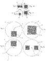
- FIG. 1 a shows a circularly designed film 1 on which a matrix barcode (two-dimensional code) 2 is printed or is applied or provided on the film 1 on the basis of other application methods.
- a hole or recess 3 is provided in the film 1.
- the hole 3 can be located, for example, in the middle of the circularly designed film 1.
- the matrix barcode 2 which is preferably designed as a square surface, can also be positioned such that it is in the middle, for example (cf.
- Fig.1a or hole 3 in another area of the matrix barcode. It is not a problem that the hole 3 is positioned within the matrix barcode 2, since the information on the matrix barcode 2 is contained several times and thus there is an increased redundancy of the information.
- the film 1 is preferably placed or positioned in an injection mold and the material for the injection molding process is introduced through an injection channel which leads through the hole 3 into the injection mold. This allows the film 1 to be back-injected.
- the injection channel usually and preferably has a diameter of 1-3 mm, so that the hole 3, which preferably has at least the same diameter as the injection channel, and also if it leads directly through the bar code 2 or is provided in the area of the matrix bar code 2 is, due to the redundant design of the matrix barcode 2, not a problem (for example loss of information).
- Figs. 1b - 1d show further embodiments of the positioning of the matrix barcode 2 on the film 1.
- two matrix barcodes are positioned to the side of hole 3 and hole 3 is located outside the matrix barcodes 2.
- the matrix barcode 2 can also be positioned below the hole 3.
- the matrix bar code (s) 2 can overlap with the recess or the hole 3 for the injection channel or can be arranged to the side thereof.
- the shape of the film 1, the positioning and the number of matrix barcodes (also with regard to hole 3) is not the same as that in FIGS Figs. 1a - 1d or Figs. 2a - 2d illustrated embodiments limited. Rather, depending on the special requirements of practice, this can be chosen and varied as desired.
- the film 1 can be used for the production of an injection molded plastic object, in particular a closure lid for containers, wherein the film 1 can be provided as a carrier film. In addition to sealing lids, the film 1 can also be provided on other objects such as side surfaces of beer crates and the like.
- the film or carrier film 1 is provided with the matrix barcode (s) 2 (for example printed).
- the carrier film 1 can also be provided with a coating. This coating can form a further protective layer or protective film and is preferably provided on the side of the film 1 which has the matrix barcode 2 in order to be able to protect the matrix barcode 2 from external influences. In this way, a multi-layer sandwich film can be provided.
- the coating is preferably provided from a translucent plastic.
- the protective layer preferably forms the side of the film facing the viewer when it is injected into a molded plastic object in order to be provided so that it can be read from the outside but is nevertheless protected from the environment.
- the film 1 can also form the outermost layer when viewed from the viewer. Inserted back-injected, in particular in an injection-molded object, the matrix barcode 2 is then preferably provided on the inside or back of the film 1, as seen by the viewer, so that the film 1 itself forms a protective layer for the matrix barcode 2. In this case, it is not absolutely necessary to provide a further protective layer (on the inner side of the film with respect to the sprayed object); however, this can be advantageous for protecting the matrix barcode 2 from the material to be injected.
- the film 1, as described above, can also be coated with a plastic material, in particular polyethylene (PE), polypropylene (PP), or another material or a film layer.
- a plastic material in particular polyethylene (PE), polypropylene (PP), or another material or a film layer.
- this coating preferably forms the uppermost layer of film 1 when viewed from the viewer; is therefore preferably when the film is provided on an upper side of the sprayed object on the visible side or outside of the sprayed object.
- the matrix barcode 2 is then provided between the film 1 and the coating.
- the film 1 itself can consist of polypropylene (PP), high-density polyethylene or another translucent polymer, in particular if it is provided directed towards the outside or visible side of an injected object.
- PP polypropylene
- the matrix barcode 2 can advantageously be read out particularly easily and well by a reading device and / or this information can be transmitted to a server in order to do so to be able to make logistic evaluations and / or decisions.
- the matrix barcode can contain 2 designations of origin, contents and other security-related information. To prevent counterfeiting, the matrix barcode 2 can contain consecutive numbering.
- a smartphone with a barcode scanner (generally consisting of a camera and a barcode scanner software) can be used as the reading device, for example.
- Figures 2a - 2d show further plan views of films according to the invention in an enlarged view.
- Fig. 2a again a hole 3, which is positioned in the middle of the circular film 1, the hole 3 simultaneously being in the center of the matrix barcode 2.
- the number of matrix barcodes, the positioning of the matrix barcodes on the film and the shape of the film 1 can be freely designed and selected.
- the invention also relates to codes applied without a carrier.
- the matrix barcode (“2D barcode”) can be printed on from the outside after the plastic object has been sprayed, for example by means of digital printing.
- a cover such as can be used for chemical containers, pharmaceuticals, etc.
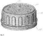
- the closure cover 10 essentially consists of an injection-molded cover part.
- the reference numerals 11 and 12 schematically denote two matrix barcode elements which are attached on the top (that is, on the side of the lid facing away from the container to be closed and the product to be filled) in such a way that they can be read optically from the outside are.
- Reference number 13 schematically designates a chip which is designed for wireless communication.
- the chip 13 is preferably not visible from the outside.
- This chip can be a transponder with an antenna, for example according to an NFC or RFID standard.
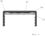
- the chip 13 can be attached to the underside of the object, for example on an inlay as a carrier as a lamination of an inner seal on the back of the cover 10.
- the cover 10 thus has an inner seal on which the chip 13 is in turn applied to an inlay as a carrier. This is an example of attaching the chip to the inside of the lid, preferably by inserting it.
- the at least one chip is preferably not visually visible to a user from the outside, that is to say, for example, neither a transponder nor an antenna can be seen by a user. This can be achieved, for example, with a non-transparent film.
- a plurality of wirelessly communicating chips can also be provided, which communicate, for example, according to different frequencies and / or protocols, and which have a common antenna or each have their own antenna.
- the chip 13 can be back-injected together with a film having the matrix barcode elements 11, 12 together with the remaining sealing cover 10.
- the chip 13 is integrated into the plastic material of the cover 10.
- the chip 13 is designed for wireless communication.
- it can be designed to communicate wirelessly according to an NFC standard or according to UHF.
- the communication preferably consists in writing (preferably lockable) the chip with data and reading the data from the chip inseparably.
- the chip is designed so that data / information can be written to it wirelessly. After this data / information in the chip 13 has been written to via a wireless interface, further modification or rewriting of the chip 13 can then be blocked ("locked").
- the chip 13 can have data, which is preferably after reading out data from the matrix barcodes 11, 12 generated based on this read data, respectively. is supplemented by further data and then written into the chip 13.
- the chip can be delivered on rolls from which individual inlays are manufactured, each of which has a chip, these inlays then being used on the rear side of the closure cover 10 in such a way that they cover an inner seal provided on the rear side.
- the chip 13 can preferably be written in the course of filling the associated container to be closed by the cover 10.
- the QR code on the closure cap 10 can thus be read out on a filling line.
- the at least one chip 13 can then be written in the closure cover 10 and then locked, that is to say blocked for further writing.
- only the read-only function of the chip 13 remains.
- “barcode” and “wirelessly readable chip” are inseparably connected as information technology elements and cannot be used again.
- the chip 13 is preferably designed for wireless communication according to several standards, for example both according to the UHF and the NFC standard.
- the UHF standard is then preferably used.
- the NFC standard is preferably used to check the authenticity of the contents and to convey further information, possibly even through an outer packaging of the container.
- Data can be read out of the chip 13 on the basis of the NFC standard, for example by means of NFC-compatible smartphones or other NFC-compatible handsets.
- the smartphone or handheld device can then establish a connection to a background system, where further relevant information is stored (for example composition, dosage, expiry date, intended use, etc. of the goods filled in the associated container).
- the chip 13 is provided on a carrier material, which is then inserted into a tool together with the film carrying the matrix bar codes 11, 12 and then back-injected.
- any other conceivable, in particular two-dimensional, code can also be used in the context of the invention instead of a matrix barcode.
- a bar code can be used instead of or in combination with a matrix bar code.
- Different types of two-dimensional codes or in combination with one-dimensional codes can be used on a film. There are also no restrictions with regard to the configuration of the shape of the film.
- the film can be circular, rectangular or in any other shape.
Landscapes
- Engineering & Computer Science (AREA)
- Microelectronics & Electronic Packaging (AREA)
- Computer Networks & Wireless Communication (AREA)
- Computer Hardware Design (AREA)
- Physics & Mathematics (AREA)
- General Physics & Mathematics (AREA)
- Theoretical Computer Science (AREA)
- Injection Moulding Of Plastics Or The Like (AREA)
- Closures For Containers (AREA)
Description
- Die vorliegende Erfindung bezieht sich auf einen gespritzten Kunststoffgegenstand, insbesondere einen Verschlussdeckel für Behälter sowie ein Verfahren zum Konfigurieren eines solchen gespritzten Kunststoffgegenstands bzw. Verschlussdeckels.
- Jeder Verschluss - ausgestattet mit einer Erstöffnungsgarantie - erhält damit eine einmalige und unverwechselbare Identität, mit der das verschlossene Produkt über die gesamte Lieferkette vom Hersteller bis zum Endabnehmer lückenlos bis auf Produktebene dokumentiert werden kann. Zudem vermittelt das Verfahren alle Informationen über das Produkt wie Produktionsdaten, Zusammensetzung, Anwendungsvorschriften usw., die in einer entsprechenden Datenbank gespeichert sind.
- Die Druckschrift
US 2011/218730 A1 offenbart ein Verfahren zum Verwalten eines Datencenters unter Verwendung eines Mobilgeräts, wobei das Verfahren Folgendes umfasst: (a) In Reaktion auf eine Benutzeranfrage verursacht das Mobilgerät einen Identifikationsprüfer, um Informationen von einem oder mehreren Identifikationsanbieter zu erhalten, die an vorbestimmten Orten in dem Datencenter angeordnet sind und bestimmt einen Standort eines mobilen Geräts in dem Datencenter; (b) das mobile Gerät fordert eine Datencenter-Karte von einem Datencenter-Verwaltungssystem an, zeigt mindestens einen Teil der Karte auf einer Anzeige für mobile Geräte an und zeigt den Standort des mobilen Geräts auf mindestens einem Teil der Karte an; und (c) das Mobilgerät erhält vom Rechenzentrumsverwaltungssystem einen Geräteort eines Geräts im Rechenzentrum. Anspruch 1 ist gegenüber diesem Dokument abgegrenzt. - Aus der
EP 1 910 983 B1 ist ein gespritzter Gegenstand aus Kunststoff bekannt, der eine mit dem Kunststoffinaterial des Gegenstandes hinterspritzte Folie und ein zwischen der Folie und dem gespritzten Kunststoffmaterial des Gegenstandes oder in der Folie integriert vorgesehenes RFID-Modul (insbesondere ein NFC-Chip) aufweist, wobei das RFID-Modul Antennen aufweist und die Folie gelocht ist. Weiterhin weist das RFID-Modul ein Loch auf und das Loch des RFID-Moduls ist konzentrisch um das Loch der Folie angeordnet, so dass sich das Material für den Spritzgießvorgang durch das Loch in der Folie und das Loch des RFID-Moduls hindurch einbringen lässt. Hierdurch lassen sich beispielsweise Verschlussdeckel herstellen. Allerdings sind die Kosten für ein derartiges RFID-Modul (oder NFC-Transponders) im Vergleich zu den Gesamtkosten eines gespritzten Gegenstandes, insbesondere eines einfachen gespritzten Verschlussdeckels, relativ hoch. Weiterhin bedingt ein mit einem RFID-Modul (oder NFC-Chip) versehener Kunststoffgegenstand aufgrund der Materialmischung besondere technische Maßnahmen beim Recycling. - Dementsprechend ist es eine Aufgabe der vorliegenden Erfindung, einen verbesserten, insbesondere in der Herstellung kostengünstigeren, gespritzten Kunststoffgegenstand, sowie ein Verfahren zu dessen Konfiguration bereitzustellen.
- Diese Aufgabe wird durch die Gegenstände der unabhängigen Patentansprüche gelöst. Weitere vorteilhafte Ausgestaltungen sind in den abhängigen Ansprüchen zu finden.
- Ein erster Aspekt der Erfindung betrifft einen gespritzten Kunststoffgegenstand, insbesondere Verschlussdeckel für Behälter,
aufweisend wenigstens ein 2d-Barcodeelement, wie bspw. ein QR-Code, auf seiner Oberseite,
sowie wenigstens einen vorzugsweise integrierten Chip, bspw. in Form eines Transponders mit Antenne, bspw. gemäß einem NFC- oder RFID-Standard, der drahtlos beschreibbar und auslesbar ist, wobei ein weiteres Beschreiben des Chips nach einem ersten Beschreiben des Chips durch ein drahtloses Signal sperrbar ist, der Chip indessen weiterhin auslesbar ist.
Unter "integriert" ist auch ein bspw. auf der von dem 2d-Barcodeelement abgewandten Seite eingelegter Chip zu verstehen. Vorzugsweise ist der Chip für einen Benutzer von außen nicht ersichtlich.
Dabei können Informationen, die in dem wenigstens einen 2d-Barcodelement codiert enthalten sind, auch in dem Chip unveränderbar eingeschrieben sein.
Der Chip kann auf einem auf der Rückseite des Gegenstands eingelegten Inlay angeordnet sein.
Dabei kann das Inlay eine Innendichtung auf der Rückseite eines Verschlussdeckels kaschieren.
Der Chip kann zusammen mit einer mit dem 2d Barcodeelement bedruckten Folie hinterspritzt sein.
Der Chip kann für eine NFC- und/oder UHF-Kommunikation ausgelegt sein. - Hinterspritzen bedeutet in diesem Zusammenhang, dass das Kunststoffmaterial sich vom Betrachter aus gesehen hinter der Folie verfestigt. Durch das Hinterspritzen der Folie wird eine besonders innige Verbindung zwischen der Folie und dem Kunststoffmaterial herbeigeführt, und die Folie ist untrennbar mit dem Kunststoffmaterial verbunden. Die abdeckende (Schutz-)Folie stellt einen Schutz des Matrix-Barcodes vor externen Einflüssen, wie beispielsweise UV-Strahlung oder mechanischem Abrieb, beispielsweise durch Verkratzen, sicher. Die Verwendung des Matrix-Barcodes sorgt zudem für eine kostengünstige Herstellung des Kunststoffgegenstandes, da ein Matrix-Barcode einfach aufgebracht (aufgedruckt) werden kann und somit günstiger als die Herstellung und Anbringung beispielsweise eines RFID-Moduls oder NFC-Moduls ist. Zudem ist die Wiederverwertung des Kunststoffgegenstandes insbesondere durch die Bereitstellung des Matrix-Barcodes anstatt eines RFID-Moduls verbessert, da ersterer keine elektronischen Komponenten aufweist.
- Der Matrix-Barcode ("2D- Barcode") kann insbesondere von außen nach dem Spritzen des Kunststoffgegenstands aufgedruckt werden, bspw. durch einen Digitaldruck. In diesem Fall ist insbesondere keine weitere Folie erforderlich. Insbesondere kann der aufgedruckte Barcode somit die äußerste Schicht darstellen, eine schützende Folie, Schutzschicht etc. sind daher rein optional.
Ausweislich https://de.wikipedia.org/wiki/Digitaldruck ist:
Digitaldruck (auch kurz "Digidruck") bezeichnet eine Gruppe von Druckverfahren, bei denen das Druckbild direkt von einem Computer in eine Druckmaschine übertragen wird, ohne dass eine statische Druckform benutzt wird. - Weitere Merkmale, Vorteile und Eigenschaften der Erfindung sollen nunmehr anhand der Ausführungsbeispiele und der Figuren der begleitenden Zeichnungen erläutert werden.
- Figs. 1a - 1d
- zeigen vier verschiedene Draufsichten von Folien.
- Figs. 2a - 2d
- zeigen weitere Draufsichten von Folien in einer vergrößerten Ansicht.
- Fig. 3.
- zeigt einen erfindungsgemäßen Verschlussdeckel, aufweisend wenigstens einen QR Code auf der Vorderseite sowie einen integrierten Chip, der drahtlos wenigstens einmal beschreibbar ist und drahtlos auslesbar ist.
- Fig. 4.
- zeigt eine Innendichtung aus PE-Schaum mit einem auf einem Inlay angeordneten Chip.
- Fig. 5.
- zeigt einen Querschnitt des Verschlussdeckels mit eingelegter Innendichtung, auf der rückseitig das Inlay mit dem Chip angeordnet ist. Es handelt sich um eine Skizze, die Maßstäbe entsprechen nicht zwangsläufig der Realität.
- Dabei zeigen die
Figs. 1a - 1d verschiedene Positionierungen von Matrix-Barcodes 2 auf einer kreisförmig ausgestalteten Folie 1. Die Folie 1 kann jedoch auch jede andere symmetrische oder asymmetrische Form (bspw. quadratisch, rechteckig, mehreckig, oval, rund etc.) aufweisen. Fig. la zeigt eine kreisförmig ausgestaltete Folie 1 auf welcher ein Matrix-Barcode (zweidimensionaler Code) 2 aufgedruckt ist oder aufgrund von anderen Aufbringungsverfahren auf der Folie 1 aufgebracht bzw. vorgesehen ist. In der Folie 1 ist ein Loch bzw. eine Ausnehmung 3 vorgesehen. Dabei kann sich das Loch 3 beispielsweise in der Mitte der kreisförmig ausgestalteten Folie 1 befinden. Weiterhin kann der Matrix-Barcode 2, der vorzugsweise als quadratische Fläche ausgestaltet ist, ebenfalls derart positioniert sein, dass dieser beispielsweise in der Mitte (vgl.Fig.1a ) oder in einem anderen Bereich des Matrix-Barcodes das Loch 3 aufweist. Dabei ist es kein Problem, dass das Loch 3 innerhalb des Matrix-Barcodes 2 positioniert ist, da die Informationen auf dem Matrix-Barcode 2 mehrfach enthalten sind und somit eine erhöhte Redundanz der Informationen vorhanden ist. Die Folie 1 wird vorzugsweise in eine Spritzgussform eingelegt bzw. positioniert und das Material für den Spritzgießvorgang wird durch einen Einspritzkanal, der durch das Loch 3 in die Spritzgussform führt, eingebracht. Dadurch kann eine Hinterspritzung der Folie 1 erfolgen. Der Einspritzkanal hat üblicherweise und bevorzugt einen Durchmesser von 1 - 3mm, so dass das Loch 3, welches vorzugsweise wenigstens denselben Durchmesser wie der Einspritzkanal hat, und auch wenn es direkt durch den Barcode 2 führt bzw. in dem Bereich des Matrix-Barcodes 2 vorgesehen ist, aufgrund der redundanten Ausgestaltung des Matrix-Barcodes 2 kein Problem (also bspw. Informationsverlust) darstellt. -
Figs. 1b - 1d zeigen weitere Ausführungsformen der Positionierung des Matrix-Barcodes 2 auf der Folie 1. Beispielsweise können, wie inFig. 1b dargestellt, zwei Matrix-Barcodes seitlich von Loch 3 positioniert sein und das Loch 3 sich außerhalb der Matrix-Barcodes 2 befinden. GemäßFig. 1c kann aber auch der Matrix-Barcode 2 unterhalb des Lochs 3 positioniert sein. Mit anderen Worten kann/können der/die Matrix-Barcode(s) 2 mit der Ausnehmung bzw. dem Loch 3 für den Einspritzkanal überlappen oder seitlich davon angeordnet sein. Die Form der Folie 1, die Positionierung und die Anzahl der Matrix-Barcodes (auch bzgl. des Loches 3) ist jedoch nicht auf die in denFigs. 1a - 1d oder Figs. 2a - 2d dargestellten Ausführungsformen beschränkt. Vielmehr kann dies, je nach den speziellen Anforderungen der Praxis, beliebig gewählt und variiert werden. - Die Folie 1 kann dabei für die Herstellung eines gespritzten Kunststoffgegenstandes, insbesondere eines Verschlussdeckels für Behälter, verwendet werden, wobei die Folie 1 als Trägerfolie vorgesehen sein kann. Neben Verschlussdeckeln kann die Folie 1 auch auf anderen Gegenständen wie Seitenflächen von Bierkästen und dergleichen vorgesehen sein. Die Folie bzw. Trägerfolie 1 wird mit dem Matrix-Barcode(s) 2 versehen (bspw. bedruckt). Die Trägerfolie 1 kann ferner mit einer Beschichtung versehen werden. Diese Beschichtung kann eine weitere Schutzschicht bzw. Schutzfolie bilden und ist vorzugsweise auf der den Matrix-Barcode 2 aufweisenden Seite der Folie 1 vorgesehen, um den Matrix-Barcode 2 vor äußeren Einflüssen schützen zu können. Auf diese Weise kann eine mehrlagige Sandwich-Folie bereitgestellt werden. Vorzugsweise ist die Beschichtung aus einem lichtdurchlässigen Kunststoff bereitgestellt. In diesem Fall bildet die Schutzschicht vorzugsweise die dem Betrachter zugewandte Seite der Folie, wenn sie in einem gespritzten Kunststoffgegenstand hinterspritzt eingebracht ist, um von außen lesbar aber dennoch von der Umgebung geschützt bereitgestellt zu sein.
- In einer weiteren Variation kann die Folie 1 aber auch vom Betrachter aus gesehen die äußerste Schicht bilden. Insbesondere in einem gespritzten Gegenstand hinterspritzt eingebracht ist der Matrix-Barcode 2 dann vom Betrachter aus gesehen vorzugsweise auf der Innenseite bzw. Rückseite der Folie 1 vorgesehen, sodass die Folie 1 selbst eine Schutzschicht für den Matrix-Barcode 2 bildet. In diesem Fall muss nicht unbedingt eine weitere Schutzschicht (auf der dann innenliegenden Seite der Folie bzgl. des gespritzten Gegenstandes) vorgesehen sein; diese kann aber zum Schutz des Matrix-Barcodes 2 gegenüber dem einzuspritzenden Material vorteilhaft sein.
- Andererseits kann die Folie 1, wie zuvor beschrieben, auch mit einem Kunststoffmaterial, insbesondere Polyethylen (PE), Polypropylen (PP), oder einem anderen Material oder einer Folienschicht beschichtet sein. Als Schutzschicht bzw. Schutzfolie ausgebildet bildet diese Beschichtung vorzugsweise vom Betrachter aus gesehen die oberste Schicht der Folie 1; befindet sich also vorzugsweise bei Vorsehen der Folie an einer Oberseite des gespritzten Gegenstandes auf der Sichtseite bzw. Außenseite des gespritzten Gegenstandes. Zwischen der Folie 1 und der Beschichtung ist dann der Matrix-Barcode 2 vorgesehen.
- Die Folie 1 selbst kann aus Polypropylen (PP), hochdichtem Polyethylen oder einem anderen lichtdurchlässigen Polymer bestehen, insbesondere wenn sie zur Außenseite bzw. Sichtseite eines gespritzten Gegenstandes gerichtet in diesem vorgesehen ist. Durch Bereitstellung der Folie 1 und/oder der optionalen Beschichtungen aus lichtdurchlässigen Material, also wenigstens der Folienlage, welche in dem gespritzten Gegenstand nach außen zur Sichtseite hin gerichtet ist, kann vorteilhafterweise der Matrix-Barcode 2 von einem Auslesegerät besonders einfach und gut ausgelesen werden und/oder diese Informationen an einen Server übermittelt werden, um dabei logistische Auswertungen und/oder Entscheidungen treffen zu können. Dabei kann der Matrix-Barcode 2 Herkunftsbezeichnungen, Inhaltsangaben und andere sicherheitsrelevante Informationen enthalten. Zur Fälschungssicherheit kann der Matrix-Barcode 2 eine durchlaufende Nummerierung enthalten. Als Auslesegerät kann beispielsweise ein Smartphone mit einem Barcode-Scanner (in der Regel bestehend aus einer Kamera und einer Barcode-Scanner-Software) verwendet werden.
-
Figuren 2a - 2d zeigen weitere Draufsichten von erfindungsgemäßen Folien in einer vergrößerten Ansicht. Dabei zeigt beispielsweiseFig. 2a wieder ein Loch 3, das in der Mitte der kreisförmigen Folie 1 positioniert ist, wobei gleichzeitig das Loch 3 mittig in dem Matrix-Barcode 2 liegt. Wie bereits hinsichtlich denFigs. 1a - 1d erwähnt, kann die Anzahl der Matrix-Barcodes, die Positionierung der Matrix-Barcodes auf der Folie als auch die Form der Folie 1 frei gestaltet und gewählt werden. Weiterhin ist es auch denkbar, dass nicht nur ein Loch 3 in Folie 1 bereitgestellt wird, sondern mehrere Löcher, um beispielsweise den Spritzgussvorgang beschleunigen zu können. - Zum grundsätzlichen Aufbau von Folien sowie dem Verfahren zum Hinterspritzen derselben wird auch auf die Ausführungen in der
EP 1 9110 983 B1 - Auch wenn sich die oben beschriebenen Ausführungsbeispiele ausdrücklich auf folienbasierte Matrix-Codes beziehen, ist festzuhalten, dass sich die Erfindung auch auf trägerlos aufgebrachte Codes bezieht. Insbesondere kann der Matrix-Barcode ("2D- Barcode") von außen nach dem Spritzen des Kunststoffgegenstands aufgedruckt werden, bspw. durch einen Digitaldruck.
- In
Fig. 3 ist mit dem Bezugszeichen 10 ein Verschlussdeckel dargestellt, wie er beispielsweise für Chemikalienbehälter, Arzneimittel, etc. verwendbar ist. - Der Verschlussdeckel 10 besteht im Wesentlichen aus einem gespritzten Deckelteil.
- Mit den Bezugszeichen 11 und 12 sind schematisch zwei Matrix-Barcodeelemente bezeichnet, die derart auf der Oberseite (das heißt, auf der von dem zu verschließenden Behälter und dem zu füllenden Gut abgewandten Seite des Deckels) angebracht sind, dass sie von außen her optisch auslesbar sind.
- Mit dem Bezugszeichen 13 ist schematisch ein Chip bezeichnet, der zur drahtlosen Kommunikation ausgelegt ist. Der Chip 13 ist vorzugsweise von außen nicht sichtbar. Dieser Chip kann ein Transponder mit Antenne sein, bspw. gemäß einem NFC- oder RFID-Standard.
- Wie
Fig. 4 . undFig. 5 . Zeigen, kann der Chip 13 auf der Unterseite des Gegenstands, beispielsweise auf einem Inlay als Träger als Kaschierung einer Innendichtung auf der Rückseite des Deckels 10 angebracht sein. Der Deckel 10 weist somit eine Innendichtung auf, auf der wiederum der Chip 13 auf einem Inlay als Träger aufgebracht ist. Dies ist ein Beispiel für die Anbringung des Chips auf der Innenseite des Deckels vorzugsweise durch Einlegen. - Vorzugsweise ist der wenigstens eine Chip für einen Benutzer von außen nicht optisch ersichtlich, also bspw. weder Transponder noch Antenne können von einem Benutzer gesehen werden. Dies kann bspw. durch eine nichttransparente Folie erreicht werden.
- Es können auch mehrere drahtlos kommunizierende Chips vorgesehen sein, die bspw. gemäß unterschiedlichen Frequenzen und/oder Protokollen kommunizieren, und eine gemeinsame Antennen oder jeweils eine eigenen Antenne aufweisen.
- Alternativ kann der Chip 13 zusammen mit einer die Matrix-Barcodeelemente 11, 12 aufweisenden Folie zusammen mit dem übrigen Verschlussdeckel 10 hinterspritzt werden. In diesem Fall ist also der Chip 13 in das Kunststoffmaterial des Deckels 10 integriert.
- Der Chip 13 ist zur drahtlosen Kommunikation ausgelegt. Insbesondere kann er dazu ausgelegt sein, gemäß einem NFC-Standard oder gemäß UHF drahtlos zu kommunizieren. Die Kommunikation besteht vorzugsweise in einem (vorzugsweise sperrbaren) Beschreiben des Chips mit Daten und einem Auslesen der Daten aus dem Chip untrennbar.
- Insbesondere ist gemäß der Erfindung der Chip dazu ausgelegt, dass drahtlos in ihn Daten/Informationen geschrieben werden können. Nach einem Beschreiben dieser Daten/Informationen in dem Chip 13 über eine drahtlose Schnittstelle kann dann ein weiteres Verändern oder Neubeschreiben des Chips 13 gesperrt ("gelockt") werden.
- Vorzugsweise ist ein Teil der Daten, die in den Chip 13 geschrieben werden, zusätzlich bereits in den Matrix-Barcodes 11, 12 enthalten. Alternativ kann der Chip 13 Daten aufweisen, die vorzugsweise nach einem Auslesen von Daten aus den Matrix-Barcodes 11, 12 auf diesen ausgelesenen Daten beruhend erzeugt, resp. durch weitere Daten ergänzt und dann in den Chip 13 eingeschrieben wird.
- Wie bereits erwähnt, kann der Chip auf Rollen angeliefert werden, aus denen vereinzelte Inlays gefertigt werden, die jeweils einen Chip aufweisen, wobei diese Inlays dann auf der Rückseite des Verschlussdeckels 10 so eingesetzt werden, dass sie eine auf der Rückseite vorgesehene Innendichtung kaschieren.
- Vorzugsweise kann das Beschreiben des Chips 13 in Zuge des Befüllens des zugehörigen, durch den Deckel 10 zu verschließenden Behälters erfolgen. Beispielsweise kann somit auf einer Abfülllinie der QR-Code auf dem Verschlussdeckel 10 ausgelesen werden. Anschließend kann der wenigstens eine Chip 13 in dem Verschlussdeckel 10 beschrieben und dann gelockt, also für weiteres Beschreiben gesperrt werden. Es verbleibt somit nur noch die Read-Only-Funktion des Chips 13. Somit sind untrennbar als Elemente "Barcode" und "drahtlos ausgelesbarer Chip" informationstechnisch untrennbar verbunden und können auch nicht wieder verwendet werden.
- Vorzugsweise ist der Chip 13 für eine drahtlose Kommunikation gemäß mehrere Standards, bspw. sowohl gemäß dem UHF- wie auch dem NFC-Standard ausgelegt. Im logistischen Bereich erfolgt dann vorzugsweise die Verwendung des UHF-Standards. Der NFC-Standard wird vorzugsweise zur Kontrolle des Füllguts auf Authentizität und die Vermittlung von weiteren Informationen, gegebenenfalls sogar durch eine Umverpackung des Behälters hindurch verwendet.
- Das Auslesen von Daten aus dem Chip 13 unter Zugrundelegung des NFC-Standards kann beispielsweise mittels NFC-fähiger Smartphones oder anderer NFC-fähiger Handgeräte erfolgen. Das Smartphone beziehungsweise Handgerät kann dann eine Verbindung zu einem Hintergrundsystem aufbauen, wo weitere relevante Informationen abgelegt sind (beispielsweise Zusammensetzung, Dosierung, Ablaufdatum, Verwendungszweck, etc. des in dem zugehörigen Behälter abgefüllten Gutes).
- Gemäß einer weiteren Ausführungsform ist der Chip 13 auf einem Trägermaterial vorgesehen, das dann zusammen mit der den Matrix-Barcodes 11, 12 tragenden Folie in ein Werkzeug eingelegt wird und dann hinterspritzt wird.
- Die Erfindung ist nicht durch die Beschreibung anhand der Ausführungsbeispiele beschränkt. Vielmehr sind alle Merkmale beliebig miteinander kombinierbar, solange der Gegenstand weiterhin von den Ansprüchen umfasst ist. Beispielsweise kann weiterhin im Rahmen der Erfindung anstatt eines Matrix-Barcodes auch jeder andere denkbare insbesondere zweidimensionale Code verwendet werden. Weiterhin kann anstatt oder in Kombination mit einem Matrix-Barcode ein Strichcode Verwendung finden. Dabei können auf einer Folie verschiedene Arten von zweidimensionalen Codes oder in Kombination mit eindimensionalen Codes verwendet werden. Auch sind hinsichtlich der Ausgestaltung der Form der Folie keinerlei Begrenzungen vorhanden. Die Folie kann kreisförmig, rechteckig oder auch in jeglicher anderen Form ausgebildet sein.
-
- 1
- Folie
- 2
- Matrix-Barcode
- 3
- Loch
- 10
- Verschlussdeckel für Flaschen oder andere Behälter (bspw. für Pharmazeutika, Chemikalien etc.)
- 11
- Matrix Barcode
- 12
- Matrix Barcode
- 13
- wenigstens ein Chip
- 14
- Inlay
- 15
- Innendichtung
Claims (12)
- Gespritzter Kunststoffgegenstand, aufweisend:- wenigstens ein 2d-Barcodeelement (11, 12) auf der Aussenseite des Kunststoffgegenstands, sowie- wenigstens einen Chip (13), der drahtlos beschreibbar und auslesbar ist,wobei ein weiteres Beschreiben des Chips (13) nach einem ersten Beschreiben des Chips (13) sperrbar durch ein drahtloses Signal ist, der Chip indessen weiterhin auslesbar ist, dadurch gekennzeichnet, dass der gespritzte Kunststoffgegenstand ein Verschlussdeckel (10) für Behälter ist, der ein Schraubgewinde aufweist, und
wobei der Chip (13) auf die Innenseite des Verschlussdeckels (10) eingelegt ist. - Gespritzter Kunststoffgegenstand nach Anspruch 1,
wobei das 2d-Barcodeelement (11,12) nach dem Spritzgiessen des Kunststoffgegenstandes von außen aufgedruckt ist, bspw. durch einen Digitaldruck. - Gegenstand nach Anspruch 1 oder 2,
bei dem Informationen, die in dem wenigstens einen 2d-Barcodelement codiert enthalten sind, auch in dem Chip(13) unveränderbar eingeschrieben sind. - Gegenstand nach einem der vorhergehenden Ansprüche,
bei dem der Chip auf einem auf der Rückseite des Gegenstands eingelegten Inlay (14) angeordnet ist. - Gegenstand nach Anspruch 4,
bei dem das Inlay (14) eine Innendichtung (15) auf der Rückseite eines Verschlussdeckels (10) kaschiert. - Gegenstand nach Anspruch 1,
bei dem der Chip (13) vorzugsweise zusammen mit einer mit dem 2d-Barcodeelement bedruckten Folie hinterspritzt ist. - Gegenstand nach einem der vorhergehenden Ansprüche,
bei dem der Chip für eine NFC- und/oder UHF-Kommunikation ausgelegt ist. - Gegenstand nach einem der vorhergehenden Ansprüche,
bei dem der Chip (13) ein Transponder mit Antenne ist. - Gegenstand nach einem der vorhergehenden Ansprüche,
bei dem mehrere Chips (13) vorgesehen sind. - Gegenstand nach einem der vorhergehenden Ansprüche, der als Verschlussdeckel für Flaschen oder andere Behälter (10) ausgebildet ist.
- Gegenstand nach Anspruch 10,
der eine Erstöffnungsgarantie aufweist. - Gegenstand nach einem der vorhergehenden Ansprüche,
bei dem der Chip (13) durch eine nicht-transparente Folie abgedeckt ist.
Applications Claiming Priority (2)
| Application Number | Priority Date | Filing Date | Title |
|---|---|---|---|
| DE102016209224 | 2016-05-27 | ||
| DE102016210738 | 2016-06-16 |
Publications (2)
| Publication Number | Publication Date |
|---|---|
| EP3252678A1 EP3252678A1 (de) | 2017-12-06 |
| EP3252678B1 true EP3252678B1 (de) | 2020-07-08 |
Family
ID=58873616
Family Applications (1)
| Application Number | Title | Priority Date | Filing Date |
|---|---|---|---|
| EP17171959.4A Active EP3252678B1 (de) | 2016-05-27 | 2017-05-19 | Verschlussdeckel mit transponder chip und 2d-barcode |
Country Status (1)
| Country | Link |
|---|---|
| EP (1) | EP3252678B1 (de) |
Family Cites Families (3)
| Publication number | Priority date | Publication date | Assignee | Title |
|---|---|---|---|---|
| DE102005036258A1 (de) | 2005-08-02 | 2007-02-08 | Pierre Chappuis | Dekorfolien und Verfahren zu deren Herstellung |
| US20080041947A1 (en) * | 2006-08-14 | 2008-02-21 | Allen Hollister | System for identifying contents of closed containers using RFID tags |
| US9097528B2 (en) * | 2010-03-05 | 2015-08-04 | Vmware, Inc. | Managing a datacenter using mobile devices |
-
2017
- 2017-05-19 EP EP17171959.4A patent/EP3252678B1/de active Active
Non-Patent Citations (1)
| Title |
|---|
| None * |
Also Published As
| Publication number | Publication date |
|---|---|
| EP3252678A1 (de) | 2017-12-06 |
Similar Documents
| Publication | Publication Date | Title |
|---|---|---|
| EP2054846B1 (de) | Verfahren zur herstellung eines behältnisses und ein behältnis zur lagerung und zum transport von stück- und schüttgütern | |
| EP3948668B1 (de) | Kennzeichnungssatz zum kennzeichnen eines pharmazeutischen gefässes und pharmazeutische konfektionierungseinheit | |
| EP1457301B1 (de) | Behälter aus Kunststoff mit integriertem Transponder | |
| WO2011140666A1 (de) | Verfahren zum herstellen eines ein flächiges elektronisches element aufweisenden kunststoffbehälters, kunststoffbehälter hergestellt nach diesem verfahren sowie spritzgusswerkzeug zum durchführen des verfahrens | |
| DE102004061633A1 (de) | Behälter mit Transponder | |
| EP3411239B1 (de) | Druckmaschine zum bedrucken von behältern | |
| EP3552153B1 (de) | Verfahren zum verbinden eines geschirrteils mit einem informationsträger und vorrichtung mit einem geschirrteil und einem informationsträger | |
| WO2009018922A1 (de) | Warenverpackung mit deckfolie | |
| EP2799205B1 (de) | Matrix-Barcode auf hinterspritzter Folie | |
| DE112013007134T5 (de) | Eine Versiegelungsplakette mit leitenden Merkmalen zum Verhindern der Fälschung eines Produkts und Verfahren zum Herstellen eines solchen | |
| EP3460721B1 (de) | Rfid-etikett mit schutz der rfid-funktion | |
| EP2805770B1 (de) | Behälter für den Laborbereich sowie Verfahren zur Kennzeichnung eines derartigen Behälters | |
| DE102014208780A1 (de) | Verfahren zum Überwachen eines Beladezustands und eines Belade- oder Entladevorgangs eines Kraftfahrzeugs | |
| EP2482237B1 (de) | Körper in Form einer Verpackung oder eines Formteils mit einer RFID-Antenne | |
| WO2023138865A1 (de) | Multifunktionsetikett, system und verfahren zum herstellen eines multifunktionsetiketts | |
| EP2671194B1 (de) | Behälter und verpackungseinheit | |
| EP1910983B1 (de) | Gespritzter Gegenstand aus Kunststoff und Verfahren zu dessen Herstellung | |
| EP3252678A1 (de) | Verschlussdeckel mit transponder chip und 2d-barcode | |
| EP3701423B1 (de) | Sicherheitsetikett zum nachweis missbräuchlicher manipulationsversuche | |
| WO2011054406A1 (de) | Behälter insbesondere flaschenkasten mit inmould-label | |
| WO2008034469A1 (de) | Im zweikomponenten-spritzverfahren hergestellter gegenstand | |
| EP4300469A1 (de) | Multifunktionsetikett, system und verfahren zum herstellen eines multifunktionsetiketts | |
| DE102012025129B4 (de) | Inmould Datenspeicher | |
| WO2009000384A2 (de) | System zur kontrolle einer medikamenteneinnahme | |
| DE102006018461A1 (de) | Formteil aus faserverstärktem Kunststoff mit mindestens einem RFID-Transponder |
Legal Events
| Date | Code | Title | Description |
|---|---|---|---|
| PUAI | Public reference made under article 153(3) epc to a published international application that has entered the european phase |
Free format text: ORIGINAL CODE: 0009012 |
|
| STAA | Information on the status of an ep patent application or granted ep patent |
Free format text: STATUS: THE APPLICATION HAS BEEN PUBLISHED |
|
| AK | Designated contracting states |
Kind code of ref document: A1 Designated state(s): AL AT BE BG CH CY CZ DE DK EE ES FI FR GB GR HR HU IE IS IT LI LT LU LV MC MK MT NL NO PL PT RO RS SE SI SK SM TR |
|
| AX | Request for extension of the european patent |
Extension state: BA ME |
|
| STAA | Information on the status of an ep patent application or granted ep patent |
Free format text: STATUS: REQUEST FOR EXAMINATION WAS MADE |
|
| 17P | Request for examination filed |
Effective date: 20180530 |
|
| RBV | Designated contracting states (corrected) |
Designated state(s): AL AT BE BG CH CY CZ DE DK EE ES FI FR GB GR HR HU IE IS IT LI LT LU LV MC MK MT NL NO PL PT RO RS SE SI SK SM TR |
|
| STAA | Information on the status of an ep patent application or granted ep patent |
Free format text: STATUS: EXAMINATION IS IN PROGRESS |
|
| 17Q | First examination report despatched |
Effective date: 20190617 |
|
| RAP1 | Party data changed (applicant data changed or rights of an application transferred) |
Owner name: MEGA-NOVA AG |
|
| GRAP | Despatch of communication of intention to grant a patent |
Free format text: ORIGINAL CODE: EPIDOSNIGR1 |
|
| STAA | Information on the status of an ep patent application or granted ep patent |
Free format text: STATUS: GRANT OF PATENT IS INTENDED |
|
| INTG | Intention to grant announced |
Effective date: 20200214 |
|
| GRAS | Grant fee paid |
Free format text: ORIGINAL CODE: EPIDOSNIGR3 |
|
| GRAA | (expected) grant |
Free format text: ORIGINAL CODE: 0009210 |
|
| STAA | Information on the status of an ep patent application or granted ep patent |
Free format text: STATUS: THE PATENT HAS BEEN GRANTED |
|
| AK | Designated contracting states |
Kind code of ref document: B1 Designated state(s): AL AT BE BG CH CY CZ DE DK EE ES FI FR GB GR HR HU IE IS IT LI LT LU LV MC MK MT NL NO PL PT RO RS SE SI SK SM TR |
|
| REG | Reference to a national code |
Ref country code: CH Ref legal event code: EP Ref country code: AT Ref legal event code: REF Ref document number: 1289256 Country of ref document: AT Kind code of ref document: T Effective date: 20200715 |
|
| REG | Reference to a national code |
Ref country code: DE Ref legal event code: R096 Ref document number: 502017006046 Country of ref document: DE |
|
| REG | Reference to a national code |
Ref country code: IE Ref legal event code: FG4D Free format text: LANGUAGE OF EP DOCUMENT: GERMAN |
|
| REG | Reference to a national code |
Ref country code: LT Ref legal event code: MG4D |
|
| REG | Reference to a national code |
Ref country code: NL Ref legal event code: MP Effective date: 20200708 |
|
| PG25 | Lapsed in a contracting state [announced via postgrant information from national office to epo] |
Ref country code: FI Free format text: LAPSE BECAUSE OF FAILURE TO SUBMIT A TRANSLATION OF THE DESCRIPTION OR TO PAY THE FEE WITHIN THE PRESCRIBED TIME-LIMIT Effective date: 20200708 Ref country code: SE Free format text: LAPSE BECAUSE OF FAILURE TO SUBMIT A TRANSLATION OF THE DESCRIPTION OR TO PAY THE FEE WITHIN THE PRESCRIBED TIME-LIMIT Effective date: 20200708 Ref country code: HR Free format text: LAPSE BECAUSE OF FAILURE TO SUBMIT A TRANSLATION OF THE DESCRIPTION OR TO PAY THE FEE WITHIN THE PRESCRIBED TIME-LIMIT Effective date: 20200708 Ref country code: BG Free format text: LAPSE BECAUSE OF FAILURE TO SUBMIT A TRANSLATION OF THE DESCRIPTION OR TO PAY THE FEE WITHIN THE PRESCRIBED TIME-LIMIT Effective date: 20201008 Ref country code: PT Free format text: LAPSE BECAUSE OF FAILURE TO SUBMIT A TRANSLATION OF THE DESCRIPTION OR TO PAY THE FEE WITHIN THE PRESCRIBED TIME-LIMIT Effective date: 20201109 Ref country code: LT Free format text: LAPSE BECAUSE OF FAILURE TO SUBMIT A TRANSLATION OF THE DESCRIPTION OR TO PAY THE FEE WITHIN THE PRESCRIBED TIME-LIMIT Effective date: 20200708 Ref country code: NO Free format text: LAPSE BECAUSE OF FAILURE TO SUBMIT A TRANSLATION OF THE DESCRIPTION OR TO PAY THE FEE WITHIN THE PRESCRIBED TIME-LIMIT Effective date: 20201008 Ref country code: ES Free format text: LAPSE BECAUSE OF FAILURE TO SUBMIT A TRANSLATION OF THE DESCRIPTION OR TO PAY THE FEE WITHIN THE PRESCRIBED TIME-LIMIT Effective date: 20200708 Ref country code: GR Free format text: LAPSE BECAUSE OF FAILURE TO SUBMIT A TRANSLATION OF THE DESCRIPTION OR TO PAY THE FEE WITHIN THE PRESCRIBED TIME-LIMIT Effective date: 20201009 |
|
| PG25 | Lapsed in a contracting state [announced via postgrant information from national office to epo] |
Ref country code: LV Free format text: LAPSE BECAUSE OF FAILURE TO SUBMIT A TRANSLATION OF THE DESCRIPTION OR TO PAY THE FEE WITHIN THE PRESCRIBED TIME-LIMIT Effective date: 20200708 Ref country code: RS Free format text: LAPSE BECAUSE OF FAILURE TO SUBMIT A TRANSLATION OF THE DESCRIPTION OR TO PAY THE FEE WITHIN THE PRESCRIBED TIME-LIMIT Effective date: 20200708 Ref country code: PL Free format text: LAPSE BECAUSE OF FAILURE TO SUBMIT A TRANSLATION OF THE DESCRIPTION OR TO PAY THE FEE WITHIN THE PRESCRIBED TIME-LIMIT Effective date: 20200708 Ref country code: IS Free format text: LAPSE BECAUSE OF FAILURE TO SUBMIT A TRANSLATION OF THE DESCRIPTION OR TO PAY THE FEE WITHIN THE PRESCRIBED TIME-LIMIT Effective date: 20201108 |
|
| PG25 | Lapsed in a contracting state [announced via postgrant information from national office to epo] |
Ref country code: NL Free format text: LAPSE BECAUSE OF FAILURE TO SUBMIT A TRANSLATION OF THE DESCRIPTION OR TO PAY THE FEE WITHIN THE PRESCRIBED TIME-LIMIT Effective date: 20200708 |
|
| REG | Reference to a national code |
Ref country code: DE Ref legal event code: R097 Ref document number: 502017006046 Country of ref document: DE |
|
| PG25 | Lapsed in a contracting state [announced via postgrant information from national office to epo] |
Ref country code: IT Free format text: LAPSE BECAUSE OF FAILURE TO SUBMIT A TRANSLATION OF THE DESCRIPTION OR TO PAY THE FEE WITHIN THE PRESCRIBED TIME-LIMIT Effective date: 20200708 Ref country code: EE Free format text: LAPSE BECAUSE OF FAILURE TO SUBMIT A TRANSLATION OF THE DESCRIPTION OR TO PAY THE FEE WITHIN THE PRESCRIBED TIME-LIMIT Effective date: 20200708 Ref country code: SM Free format text: LAPSE BECAUSE OF FAILURE TO SUBMIT A TRANSLATION OF THE DESCRIPTION OR TO PAY THE FEE WITHIN THE PRESCRIBED TIME-LIMIT Effective date: 20200708 Ref country code: CZ Free format text: LAPSE BECAUSE OF FAILURE TO SUBMIT A TRANSLATION OF THE DESCRIPTION OR TO PAY THE FEE WITHIN THE PRESCRIBED TIME-LIMIT Effective date: 20200708 Ref country code: DK Free format text: LAPSE BECAUSE OF FAILURE TO SUBMIT A TRANSLATION OF THE DESCRIPTION OR TO PAY THE FEE WITHIN THE PRESCRIBED TIME-LIMIT Effective date: 20200708 Ref country code: RO Free format text: LAPSE BECAUSE OF FAILURE TO SUBMIT A TRANSLATION OF THE DESCRIPTION OR TO PAY THE FEE WITHIN THE PRESCRIBED TIME-LIMIT Effective date: 20200708 |
|
| PLBE | No opposition filed within time limit |
Free format text: ORIGINAL CODE: 0009261 |
|
| STAA | Information on the status of an ep patent application or granted ep patent |
Free format text: STATUS: NO OPPOSITION FILED WITHIN TIME LIMIT |
|
| PG25 | Lapsed in a contracting state [announced via postgrant information from national office to epo] |
Ref country code: AL Free format text: LAPSE BECAUSE OF FAILURE TO SUBMIT A TRANSLATION OF THE DESCRIPTION OR TO PAY THE FEE WITHIN THE PRESCRIBED TIME-LIMIT Effective date: 20200708 |
|
| 26N | No opposition filed |
Effective date: 20210409 |
|
| PG25 | Lapsed in a contracting state [announced via postgrant information from national office to epo] |
Ref country code: SK Free format text: LAPSE BECAUSE OF FAILURE TO SUBMIT A TRANSLATION OF THE DESCRIPTION OR TO PAY THE FEE WITHIN THE PRESCRIBED TIME-LIMIT Effective date: 20200708 |
|
| PG25 | Lapsed in a contracting state [announced via postgrant information from national office to epo] |
Ref country code: SI Free format text: LAPSE BECAUSE OF FAILURE TO SUBMIT A TRANSLATION OF THE DESCRIPTION OR TO PAY THE FEE WITHIN THE PRESCRIBED TIME-LIMIT Effective date: 20200708 |
|
| PG25 | Lapsed in a contracting state [announced via postgrant information from national office to epo] |
Ref country code: LU Free format text: LAPSE BECAUSE OF NON-PAYMENT OF DUE FEES Effective date: 20210519 Ref country code: MC Free format text: LAPSE BECAUSE OF FAILURE TO SUBMIT A TRANSLATION OF THE DESCRIPTION OR TO PAY THE FEE WITHIN THE PRESCRIBED TIME-LIMIT Effective date: 20200708 |
|
| REG | Reference to a national code |
Ref country code: BE Ref legal event code: MM Effective date: 20210531 |
|
| PG25 | Lapsed in a contracting state [announced via postgrant information from national office to epo] |
Ref country code: IE Free format text: LAPSE BECAUSE OF NON-PAYMENT OF DUE FEES Effective date: 20210519 |
|
| PG25 | Lapsed in a contracting state [announced via postgrant information from national office to epo] |
Ref country code: BE Free format text: LAPSE BECAUSE OF NON-PAYMENT OF DUE FEES Effective date: 20210531 |
|
| PG25 | Lapsed in a contracting state [announced via postgrant information from national office to epo] |
Ref country code: HU Free format text: LAPSE BECAUSE OF FAILURE TO SUBMIT A TRANSLATION OF THE DESCRIPTION OR TO PAY THE FEE WITHIN THE PRESCRIBED TIME-LIMIT; INVALID AB INITIO Effective date: 20170519 |
|
| PG25 | Lapsed in a contracting state [announced via postgrant information from national office to epo] |
Ref country code: CY Free format text: LAPSE BECAUSE OF FAILURE TO SUBMIT A TRANSLATION OF THE DESCRIPTION OR TO PAY THE FEE WITHIN THE PRESCRIBED TIME-LIMIT Effective date: 20200708 |
|
| PG25 | Lapsed in a contracting state [announced via postgrant information from national office to epo] |
Ref country code: MK Free format text: LAPSE BECAUSE OF FAILURE TO SUBMIT A TRANSLATION OF THE DESCRIPTION OR TO PAY THE FEE WITHIN THE PRESCRIBED TIME-LIMIT Effective date: 20200708 |
|
| PG25 | Lapsed in a contracting state [announced via postgrant information from national office to epo] |
Ref country code: MT Free format text: LAPSE BECAUSE OF FAILURE TO SUBMIT A TRANSLATION OF THE DESCRIPTION OR TO PAY THE FEE WITHIN THE PRESCRIBED TIME-LIMIT Effective date: 20200708 |
|
| PGFP | Annual fee paid to national office [announced via postgrant information from national office to epo] |
Ref country code: DE Payment date: 20250603 Year of fee payment: 9 |
|
| PGFP | Annual fee paid to national office [announced via postgrant information from national office to epo] |
Ref country code: GB Payment date: 20250620 Year of fee payment: 9 |
|
| PGFP | Annual fee paid to national office [announced via postgrant information from national office to epo] |
Ref country code: FR Payment date: 20250528 Year of fee payment: 9 |
|
| PGFP | Annual fee paid to national office [announced via postgrant information from national office to epo] |
Ref country code: CH Payment date: 20250620 Year of fee payment: 9 |
|
| PGFP | Annual fee paid to national office [announced via postgrant information from national office to epo] |
Ref country code: AT Payment date: 20250528 Year of fee payment: 9 |
|
| PG25 | Lapsed in a contracting state [announced via postgrant information from national office to epo] |
Ref country code: TR Free format text: LAPSE BECAUSE OF FAILURE TO SUBMIT A TRANSLATION OF THE DESCRIPTION OR TO PAY THE FEE WITHIN THE PRESCRIBED TIME-LIMIT Effective date: 20200708 |