EP3252676A1 - Electronic equipment and beacon - Google Patents
Electronic equipment and beacon Download PDFInfo
- Publication number
- EP3252676A1 EP3252676A1 EP17169226.2A EP17169226A EP3252676A1 EP 3252676 A1 EP3252676 A1 EP 3252676A1 EP 17169226 A EP17169226 A EP 17169226A EP 3252676 A1 EP3252676 A1 EP 3252676A1
- Authority
- EP
- European Patent Office
- Prior art keywords
- exterior section
- exterior
- beacon
- component
- thickness
- Prior art date
- Legal status (The legal status is an assumption and is not a legal conclusion. Google has not performed a legal analysis and makes no representation as to the accuracy of the status listed.)
- Granted
Links
Images







Classifications
-
- G—PHYSICS
- G06—COMPUTING OR CALCULATING; COUNTING
- G06K—GRAPHICAL DATA READING; PRESENTATION OF DATA; RECORD CARRIERS; HANDLING RECORD CARRIERS
- G06K19/00—Record carriers for use with machines and with at least a part designed to carry digital markings
- G06K19/06—Record carriers for use with machines and with at least a part designed to carry digital markings characterised by the kind of the digital marking, e.g. shape, nature, code
- G06K19/067—Record carriers with conductive marks, printed circuits or semiconductor circuit elements, e.g. credit or identity cards also with resonating or responding marks without active components
- G06K19/07—Record carriers with conductive marks, printed circuits or semiconductor circuit elements, e.g. credit or identity cards also with resonating or responding marks without active components with integrated circuit chips
- G06K19/073—Special arrangements for circuits, e.g. for protecting identification code in memory
-
- G—PHYSICS
- G06—COMPUTING OR CALCULATING; COUNTING
- G06K—GRAPHICAL DATA READING; PRESENTATION OF DATA; RECORD CARRIERS; HANDLING RECORD CARRIERS
- G06K19/00—Record carriers for use with machines and with at least a part designed to carry digital markings
- G06K19/06—Record carriers for use with machines and with at least a part designed to carry digital markings characterised by the kind of the digital marking, e.g. shape, nature, code
- G06K19/067—Record carriers with conductive marks, printed circuits or semiconductor circuit elements, e.g. credit or identity cards also with resonating or responding marks without active components
- G06K19/07—Record carriers with conductive marks, printed circuits or semiconductor circuit elements, e.g. credit or identity cards also with resonating or responding marks without active components with integrated circuit chips
- G06K19/077—Constructional details, e.g. mounting of circuits in the carrier
- G06K19/07749—Constructional details, e.g. mounting of circuits in the carrier the record carrier being capable of non-contact communication, e.g. constructional details of the antenna of a non-contact smart card
-
- G—PHYSICS
- G08—SIGNALLING
- G08B—SIGNALLING SYSTEMS, e.g. PERSONAL CALLING SYSTEMS; ORDER TELEGRAPHS; ALARM SYSTEMS
- G08B5/00—Visible signalling systems, e.g. visible personal calling systems or remote indication of seats occupied
- G08B5/22—Visible signalling systems, e.g. visible personal calling systems or remote indication of seats occupied using electric transmission; using electromagnetic transmission
- G08B5/222—Personal calling arrangements or devices, i.e. paging systems
- G08B5/223—Personal calling arrangements or devices, i.e. paging systems using wireless transmission
- G08B5/224—Paging receivers with visible signalling details
- G08B5/228—Paging receivers with visible signalling details combined with other devices having a different main function, e.g. watches
-
- H—ELECTRICITY
- H04—ELECTRIC COMMUNICATION TECHNIQUE
- H04W—WIRELESS COMMUNICATION NETWORKS
- H04W12/00—Security arrangements; Authentication; Protecting privacy or anonymity
- H04W12/12—Detection or prevention of fraud
- H04W12/126—Anti-theft arrangements, e.g. protection against subscriber identity module [SIM] cloning
-
- H—ELECTRICITY
- H04—ELECTRIC COMMUNICATION TECHNIQUE
- H04W—WIRELESS COMMUNICATION NETWORKS
- H04W4/00—Services specially adapted for wireless communication networks; Facilities therefor
- H04W4/02—Services making use of location information
- H04W4/029—Location-based management or tracking services
-
- H—ELECTRICITY
- H04—ELECTRIC COMMUNICATION TECHNIQUE
- H04W—WIRELESS COMMUNICATION NETWORKS
- H04W4/00—Services specially adapted for wireless communication networks; Facilities therefor
- H04W4/80—Services using short range communication, e.g. near-field communication [NFC], radio-frequency identification [RFID] or low energy communication
-
- H—ELECTRICITY
- H10—SEMICONDUCTOR DEVICES; ELECTRIC SOLID-STATE DEVICES NOT OTHERWISE PROVIDED FOR
- H10F—INORGANIC SEMICONDUCTOR DEVICES SENSITIVE TO INFRARED RADIATION, LIGHT, ELECTROMAGNETIC RADIATION OF SHORTER WAVELENGTH OR CORPUSCULAR RADIATION
- H10F19/00—Integrated devices, or assemblies of multiple devices, comprising at least one photovoltaic cell covered by group H10F10/00, e.g. photovoltaic modules
- H10F19/80—Encapsulations or containers for integrated devices, or assemblies of multiple devices, having photovoltaic cells
-
- F—MECHANICAL ENGINEERING; LIGHTING; HEATING; WEAPONS; BLASTING
- F21—LIGHTING
- F21S—NON-PORTABLE LIGHTING DEVICES; SYSTEMS THEREOF; VEHICLE LIGHTING DEVICES SPECIALLY ADAPTED FOR VEHICLE EXTERIORS
- F21S9/00—Lighting devices with a built-in power supply; Systems employing lighting devices with a built-in power supply
- F21S9/02—Lighting devices with a built-in power supply; Systems employing lighting devices with a built-in power supply the power supply being a battery or accumulator
- F21S9/03—Lighting devices with a built-in power supply; Systems employing lighting devices with a built-in power supply the power supply being a battery or accumulator rechargeable by exposure to light
- F21S9/037—Lighting devices with a built-in power supply; Systems employing lighting devices with a built-in power supply the power supply being a battery or accumulator rechargeable by exposure to light the solar unit and the lighting unit being located within or on the same housing
-
- G—PHYSICS
- G12—INSTRUMENT DETAILS
- G12B—CONSTRUCTIONAL DETAILS OF INSTRUMENTS, OR COMPARABLE DETAILS OF OTHER APPARATUS, NOT OTHERWISE PROVIDED FOR
- G12B9/00—Housing or supporting of instruments or other apparatus
- G12B9/02—Casings; Housings; Cabinets
- G12B9/04—Details, e.g. cover
-
- Y—GENERAL TAGGING OF NEW TECHNOLOGICAL DEVELOPMENTS; GENERAL TAGGING OF CROSS-SECTIONAL TECHNOLOGIES SPANNING OVER SEVERAL SECTIONS OF THE IPC; TECHNICAL SUBJECTS COVERED BY FORMER USPC CROSS-REFERENCE ART COLLECTIONS [XRACs] AND DIGESTS
- Y02—TECHNOLOGIES OR APPLICATIONS FOR MITIGATION OR ADAPTATION AGAINST CLIMATE CHANGE
- Y02E—REDUCTION OF GREENHOUSE GAS [GHG] EMISSIONS, RELATED TO ENERGY GENERATION, TRANSMISSION OR DISTRIBUTION
- Y02E10/00—Energy generation through renewable energy sources
- Y02E10/50—Photovoltaic [PV] energy
-
- Y—GENERAL TAGGING OF NEW TECHNOLOGICAL DEVELOPMENTS; GENERAL TAGGING OF CROSS-SECTIONAL TECHNOLOGIES SPANNING OVER SEVERAL SECTIONS OF THE IPC; TECHNICAL SUBJECTS COVERED BY FORMER USPC CROSS-REFERENCE ART COLLECTIONS [XRACs] AND DIGESTS
- Y04—INFORMATION OR COMMUNICATION TECHNOLOGIES HAVING AN IMPACT ON OTHER TECHNOLOGY AREAS
- Y04S—SYSTEMS INTEGRATING TECHNOLOGIES RELATED TO POWER NETWORK OPERATION, COMMUNICATION OR INFORMATION TECHNOLOGIES FOR IMPROVING THE ELECTRICAL POWER GENERATION, TRANSMISSION, DISTRIBUTION, MANAGEMENT OR USAGE, i.e. SMART GRIDS
- Y04S40/00—Systems for electrical power generation, transmission, distribution or end-user application management characterised by the use of communication or information technologies, or communication or information technology specific aspects supporting them
- Y04S40/20—Information technology specific aspects, e.g. CAD, simulation, modelling, system security
Definitions
- the embodiments discussed herein are related to electronic equipment and a beacon.
- Beacons are wireless communication equipment that is also called radio beacons and that transmits information (beacon signals) which may be received by receiving devices.
- the beacons are used in such facilities as railroad stations and malls.
- the receiving devices that are in communication ranges for the beacons are capable of receiving the information wirelessly.
- Such services as guidance to destinations, such as ticket gates in railroad stations and stores, and information distribution for stores may be provided to users who have the receiving devices.
- Beacons that are flexible and that may be installed in any locations may be provided by use of elastomer as material of the beacons. Silicone rubber that is an example of elastomer has high weather resistance, for instance. Further, maintenance-free beacons may be provided by use of solar cells as power sources for the beacons. Utilization of such weather-resistant and maintenance-free features makes it possible to use the beacons without detachment thereof after installation of the beacons until ends of lives thereof.
- Japanese Laid-open Patent Publication Nos. 2005-227818 and 2014-160174 are examples of related art.
- beacons There have been apprehensions about theft of beacons, tampering with installation locations of the beacons, and the like. In order to deter the theft of beacons, the tampering with the installation locations of the beacons, and the like, it is demanded that the beacons are broken when being detached from the installation locations.
- electronic equipment includes a substrate configured to include a first component, a second component, and an interconnection part that couples the first component with the second component by electric interconnections; and an exterior part configured to cover the first component, the second component, and the interconnection parts, and configured to include a first exterior section that covers at least a portion of the first component, and a second exterior section that covers at least a portion of the interconnection parts, a thickness of the first exterior section being different from a thickness of the second exterior section to form a level difference in a boundary part between the first exterior section and the second exterior section.
- FIG. 1A is a plan view of a beacon 1.
- FIG. 1B is a sectional view of the beacon 1 and illustrates a section taken along a long dashed short dashed line IB-IB in FIG. 1A.
- FIG. 1C is a sectional view of the beacon 1 and illustrates a section taken along a long dashed short dashed line IC-IC in FIG. 1B .
- the beacon 1 is wireless communication equipment that transmits beacon signals.
- the beacon 1 is an example of the electronic equipment.
- the beacon 1 includes a substrate 2, electronic components 3 and 4 that are mounted on or above a top surface of the substrate 2, interconnection parts (interconnection pattern) 5 that are placed between the electronic components 3 and 4, and an exterior member 6 that covers the substrate 2, the electronic components 3 and 4, and the interconnection parts 5.
- the electronic component 3 is an example of the first component.
- the electronic component 4 is an example of the second component.
- the exterior member 6 is an example of the exterior part.
- Material of the substrate 2 and the exterior member 6 is elastomer.
- silicone rubber, fluorocarbon rubber, urethane rubber, acrylic rubber, butyl rubber, butadiene rubber, chloroprene rubber, natural rubber, and the like may be enumerated.
- the use of elastomer as the material of the substrate 2 and the exterior member 6 allows the beacon 1 flexible and to be installed in various places.
- the electronic component 3 and the electronic component 4 are mounted in a mutually separated state on the substrate 2.
- the electronic component 3 supplies electric power to the electronic component 4.
- the electronic component 3 may be a power production source such as a solar cell or may be a power source such as a primary battery and a secondary battery.
- the electronic component 4 includes an antenna, interconnections, a controller, and the like.
- the electronic component 4 may be an electronic module that includes the antenna, the interconnections, the controller, and the like.
- the controller is an integrated circuit (IC) chip, a large-scale integration (LSI) chip, or the like, for instance.
- the electronic component 4 is driven by being supplied with the electric power from the electronic component 3 and transmits the beacon signals via the antenna.
- the interconnection parts 5 link the electronic component 3 and the electronic component 4 by electric interconnections.
- the electric power is supplied from the electronic component 3 through the interconnection parts 5 to the electronic component 4.
- the interconnection parts 5 may be provided on or above the substrate 2 by formation of elastomer-based conductive paste on the substrate 2.
- the conductive paste is a mixture of metal particles and resin material.
- the metal particles copper (Cu), gold (Au), silver (Ag), palladium (Pd), nickel (Ni), tin (Sn), and the like may be enumerated.
- the resin material epoxy resin, polyimide resin, and the like may be enumerated.
- the interconnection parts 5 may be provided on or above the substrate 2 by formation of copper foil on or above the substrate 2.
- FIGs. 2A to 2C are diagrams each illustrating an example of a method of using the beacon 1.
- the beacon 1 is affixed through a fixation member 11 onto a flat surface 21 of an object 20.
- the fixation member 11 is a bonding agent, a pressure sensitive adhesive, or an adhesive compound for instance.
- the beacon 1 may be fixed to the object 20 by bonding between the substrate 2 and the object 20 through the fixation member 11.
- the beacon 1 may be fixed to the object 20 by bonding between the exterior member 6 and the object 20 through the fixation member 11.
- the beacon 1 may be fixed to the object 20 by bonding between the substrate 2 and the object 20 through the fixation member 11 and by bonding between the exterior member 6 and the object 20 through the fixation member 11.
- the beacon 1 is affixed through the fixation member 11 onto a curved surface 23 of an object 22.
- the beacon 1 may be affixed onto the curved surface 23 of the object 22 because the beacon 1 has flexibility.
- the beacon 1 is affixed through the fixation member 11 onto a band 24.
- the beacon 1 may be applied to wearable devices by being affixed onto the band 24.
- a wearable device on which the beacon 1 is affixed may be mounted on an object.
- the beacon 1 may be affixed onto flexible material such as fabric.
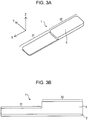
- FIG. 3A is a perspective view of the beacon 1 and FIG. 3B is a side view of the beacon 1.
- the exterior member 6 includes a first exterior section 31 and a second exterior section 32.
- a thickness of the first exterior section 31 is different from a thickness of the second exterior section 32 and the thickness of the second exterior section 32 is greater than the thickness of the first exterior section 31. Therefore, a level difference is formed in a boundary part between the first exterior section 31 and the second exterior section 32.
- a stiffness of the first exterior section 31, where the stiffness is obtained by Young's modulus multiplied by cross-sectional area for the first exterior section 31, is smaller than a stiffness of the second exterior section 32 which is obtained by Young's modulus multiplied by cross-sectional area for the second exterior section 32.
- the stiffness of the first exterior section 31 is relatively small and thus the first exterior section 31 is more prone to be deformed than the second exterior section 32.
- the stiffness of the second exterior section 32 is relatively large and thus the second exterior section 32 is more resistant to deformation than the first exterior section 31.
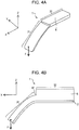
- FIG. 4A is a perspective view of the beacon 1 and FIG. 4B is a side view of the beacon 1.
- FIGs. 4A and 4B illustrate a state of the beacon 1 in which an external force F in -Z direction is exerted on the first exterior section 31.
- -Z direction is a direction in which a bottom surface of the substrate 2 faces and -Z direction is orthogonal to a longitudinal direction for the beacon 1.
- the bottom surface of the substrate 2 is a surface opposed to the top surface of the substrate 2.
- the level difference is formed in the boundary part between the first exterior section 31 and the second exterior section 32.
- the beacon 1 When the external force F in -Z direction is exerted on the first exterior section 31, accordingly, the beacon 1 is bent in -Z direction at the boundary part between the first exterior section 31 and the second exterior section 32 as illustrated in FIG. 4B .
- tensile stresses occur in the exterior member 6 and the stresses concentrate in a recess 41 on the exterior member 6.
- tears develop from the recess 41 as an origin in the boundary part between the first exterior section 31 and the second exterior section 32, so that the beacon 1 may be broken.
- the beacon 1 When the external force F in -Z direction is exerted on the second exterior section 32, the beacon 1 is bent in -Z direction at the boundary part between the first exterior section 31 and the second exterior section 32 as well. Thus tensile stresses occur in the exterior member 6 and the stresses concentrate in the recess 41 on the exterior member 6. As a result, tears develop from the recess 41 on the exterior member 6, as an origin, in the boundary part between the first exterior section 31 and the second exterior section 32, so that the beacon 1 may be broken.
- FIG. 5 is a sectional view of the beacon 1.
- the first exterior section 31 covers a portion of the interconnection parts 5 as well as the electronic component 3 and the second exterior section 32 covers a portion of the interconnection parts 5 as well as the electronic component 4.
- the boundary part between the first exterior section 31 and the second exterior section 32 is positioned on the interconnection parts 5 and thus the interconnection parts 5 are made prone to be broken when the tears develop from the boundary part between the first exterior section 31 and the second exterior section 32.
- the interconnection parts 5 formed on the substrate 2 by use of the elastomer-based conductive paste or the copper foil are easier to break than the electronic components 3 and 4.
- FIG. 6A is a perspective view of the beacon 1.
- the beacon 1 includes one notch (slit) 51 or a plurality of notches (slits) 51.
- Each notch 51 is a cutout in shape of a letter V, a letter U, or the like.
- the notch 51 is an example of the first notch.
- FIG. 6B illustrates a state of the beacon 1 in which an external force F in -Y direction is exerted on the first exterior section 31 to lift a part of the first exterior section 31.
- -Y direction is a short direction for the beacon 1.
- the short direction for the beacon 1 is a direction that is coplanar with the longitudinal direction for the beacon 1 and that is orthogonal to the longitudinal direction for the beacon 1.
- a level difference is formed in the boundary part between the first exterior section 31 and the second exterior section 32.
- +Y direction is the short direction for the beacon 1.
- the external force F in +Y direction or -Y direction is exerted on the second exterior section 32
- the tears develop from the extremities of the notches 51, so that the beacon 1 may be broken as well.
- tears develop from the recess 41 on the exterior member 6, as an origin, in the boundary part between the first exterior section 31 and the second exterior section 32, so that the beacon 1 may be broken as well.
- the beacon 1 that includes the notches 51 is more prone to be broken because the stresses concentrate at the extremities of the notches 51.
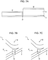
- FIG. 7A is a side view of the beacon 1.
- the notch 51 is formed on a side surface of the first exterior section 31 and formed on a side surface of the substrate 2.
- the side surface of the first exterior section 31 is a surface orthogonal to a bottom surface of the first exterior section 31.
- the bottom surface of the first exterior section 31 is in contact with the top surface of the substrate 2.
- the side surface of the substrate 2 is a surface orthogonal to the top surface of the substrate 2.
- FIG. 7B is an enlarged perspective view of the beacon 1.
- the notch 51 is adjacent to the boundary part between the first exterior section 31 and the second exterior section 32.
- FIG. 7C is an enlarged perspective view of the beacon 1.
- the notch 51 may be formed on the side surface of the first exterior section 31 and formation of the notch 51 on the side surface of the substrate 2 may be omitted.
- the fixing force by the fixation member 11 is a bonding force (bonding strength) of the bonding agent.
- the fixing force by the fixation member 11 is an adhesion force (adhesive strength) of the pressure sensitive adhesive or adhesive compound.
- FIG. 8 is a perspective view of the beacon 1.
- FIG. 8 illustrates a state of the beacon 1 in which an external force F in +X direction is exerted on the first exterior section 31 and in which an external force F in -X direction is exerted on the second exterior section 32.
- +X direction and -X direction are the longitudinal directions for the beacon 1.
- the level difference is formed in the boundary part between the first exterior section 31 and the second exterior section 32.
- FIGs. 9A and 9B are illustrations of elongations of the exterior member 6.
- FIG. 9A illustrates the exterior member 6 that includes the first exterior section 31 and the second exterior section 32 and illustrates the elongation of the first exterior section 31 and the elongation of the second exterior section 32. That is, FIG. 9A illustrates the elongations of the exterior member 6 that includes the level difference. The thickness of the second exterior section 32 is greater than the thickness of the first exterior section 31.
- FIG. 9A illustrates a state of the exterior member 6 on which the external forces F in +X direction and in -X direction are exerted.
- FIG. 9A illustrates a state of the exterior member 6 on which the external forces F in +X direction and in -X direction are exerted.
- FIG. 9B illustrates an exterior member 6A that includes exterior sections 61 and 62 having the same thickness and illustrates the elongation of the exterior section 61 and the elongation of the exterior section 62. That is, FIG. 9B illustrates the elongations of the exterior member 6A that includes no level difference. FIG. 9B illustrates a state of the exterior member 6A on which the external forces F in +X direction and in -X direction are exerted.
- the elongation of the first exterior section 31 is made larger than the elongation of the second exterior section 32 and the elongation of the exterior section 61 is made smaller than the elongation of the exterior section 62.
- the elongation of the first exterior section 31 of the exterior member 6 having the level difference is larger than the elongation of the exterior section 61 of the exterior member 6A having no level difference.
- the notches 51 are preferably formed on the first exterior section 31 because the larger the elongation of the first exterior section 31 the larger the tensile stresses.
- FIG. 10A is a perspective view of the beacon 1.
- FIG. 10B is a perspective view of the beacon 1 as seen looking from a bottom surface side of the substrate 2.
- the beacon 1 includes a groove 52.
- the groove 52 is an example of the first groove.
- the groove 52 is formed on the bottom surface of the substrate 2.
- the groove 52 linearly extends from the side surface of the substrate 2 on one side to the side surface of the substrate 2 on an opposite side. At least a portion of the boundary part between the first exterior section 31 and the second exterior section 32 lies over at least a portion of the groove 52 in plan view.
- FIG. 10A illustrates a state of the beacon 1 in which an external force F in +Z direction is exerted on the first exterior section 31.
- +Z direction is a direction which is orthogonal to the longitudinal direction for the beacon 1 and in which the top surface of the substrate 2 faces.
- a level difference is formed in the boundary part between the first exterior section 31 and the second exterior section 32.
- FIG. 11A is a plan view of the beacon 1.
- FIG. 11B is a sectional view of the beacon 1 and illustrates a section taken along a long dashed short dashed line XIB-XIB in FIG. 11A .
- the exterior member 6 of the beacon 1 illustrated in FIGs. 11A and 11B includes the first exterior section 31, the second exterior section 32, and a third exterior section 33.
- the thickness of the first exterior section 31 is different from the thickness of the second exterior section 32 and the thickness of the second exterior section 32 is greater than the thickness of the first exterior section 31. Therefore, a level difference is formed in the boundary part between the first exterior section 31 and the second exterior section 32.
- the thickness of the second exterior section 32 is different from a thickness of the third exterior section 33 and the thickness of the second exterior section 32 is greater than the thickness of the third exterior section 33. Therefore, a level difference is formed in a boundary part between the second exterior section 32 and the third exterior section 33.
- the stiffness of the first exterior section 31 and a stiffness of the third exterior section 33 are relatively small and thus the first exterior section 31 and the third exterior section 33 are more prone to be deformed than the second exterior section 32.
- the stiffness of the second exterior section 32 is relatively large and thus the second exterior section 32 is more resistant to deformation than the first exterior section 31 and the third exterior section 33.
- the thickness of the first exterior section 31 may be different from the thickness of the third exterior section 33 or the thickness of the first exterior section 31 may be identical to the thickness of the third exterior section 33.
- the level difference is formed in the boundary part between the first exterior section 31 and the second exterior section 32.
- the beacon 1 is bent at the boundary part between the first exterior section 31 and the second exterior section 32.
- tensile stresses occur in the exterior member 6 and stresses concentrate in the recess 41 on the exterior member 6.
- tears develop from the recess 41 on the exterior member 6, as an origin, in the boundary part between the first exterior section 31 and the second exterior section 32, so that the beacon 1 may be broken.
- the beacon 1 is bent at the boundary part between the second exterior section 32 and the third exterior section 33.
- the beacon 1 illustrated in FIGs. 11A and 11B includes tow level differences, for example, and thus sites where the stresses concentrate increase in number so that reliability of a break in the beacon 1 is increased.
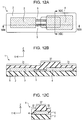
- FIG. 12A is a plan view of the beacon 1.
- FIG. 12B is a sectional view of the beacon 1 and illustrates a section taken along a long dashed short dashed line XIIB-XIIB in FIG. 12A.
- FIG. 12C is a sectional view of the beacon 1 and illustrates a section taken along a long dashed short dashed line XIIC-XIIC in FIG. 12A .
- the exterior member 6 of the beacon 1 illustrated in FIGs. 12A to 12C includes the first exterior section 31 and the second exterior section 32.
- the thickness of the first exterior section 31 is different from the thickness of the second exterior section 32 and the thickness of the second exterior section 32 is greater than the thickness of the first exterior section 31.
- first exterior section 31 is relatively small and thus the first exterior section 31 is more prone to be deformed than the second exterior section 32.
- the stiffness of the second exterior section 32 is relatively large and thus the second exterior section 32 is more resistant to deformation than the first exterior section 31.
- the first exterior section 31 covers an outer peripheral portion of the substrate 2 in plan view and the second exterior section 32 covers a portion of the substrate 2 that is inside the outer peripheral portion in plan view. That is, the second exterior section 32 is surrounded by the first exterior section 31 in plan view.
- rectangular or circular formation of the level difference increases a number of the sites where the stresses concentrate and increases the reliability of the break in the beacon 1.
- FIG. 13A is a plan view of the beacon 1.
- FIG. 13B is a sectional view of the beacon 1 and illustrates a section taken along a long dashed short dashed line XIIIB-XIIIB in FIG. 13A .
- the exterior member 6 of the beacon 1 illustrated in FIGs. 13A and 13B includes the first exterior section 31, the second exterior section 32, and a fourth exterior section 34.
- the thickness of the first exterior section 31 is different from the thickness of the second exterior section 32 and the thickness of the first exterior section 31 is greater than the thickness of the second exterior section 32. Therefore, a level difference is formed in the boundary part between the first exterior section 31 and the second exterior section 32.
- the thickness of the second exterior section 32 is different from a thickness of the fourth exterior section 34 and the thickness of the fourth exterior section 34 is greater than the thickness of the second exterior section 32. Therefore, a level difference is formed in a boundary part between the second exterior section 32 and the fourth exterior section 34.
- the stiffness of the second exterior section 32 is relatively small and thus the second exterior section 32 is more prone to be deformed than the first exterior section 31 and the fourth exterior section 34.
- the stiffness of the first exterior section 31 and a stiffness of the fourth exterior section 34 are relatively large and thus the first exterior section 31 and the fourth exterior section 34 are more resistant to deformation than the second exterior section 32.
- the thickness of the first exterior section 31 may be different from the thickness of the fourth exterior section 34 or the thickness of the first exterior section 31 may be identical to the thickness of the fourth exterior section 34.
- the level difference is formed in the boundary part between the first exterior section 31 and the second exterior section 32.
- the beacon 1 is bent at the boundary part between the first exterior section 31 and the second exterior section 32.
- tensile stresses occur in the exterior member 6 and stresses concentrate in the recess 41 on the exterior member 6.
- tears develop from the recess 41 on the exterior member 6, as an origin, in the boundary part between the first exterior section 31 and the second exterior section 32, so that the beacon 1 may be broken.
- the level difference is formed in the boundary part between the second exterior section 32 and the fourth exterior section 34.
- the beacon 1 is bent at the boundary part between the second exterior section 32 and the fourth exterior section 34.
- tensile stresses occur in the exterior member 6 and stresses concentrate in a recess 43 on the exterior member 6.
- tears develop from the recess 43 on the exterior member 6, as an origin, in the boundary part between the second exterior section 32 and the fourth exterior section 34, so that the beacon 1 may be broken.
- the beacon 1 illustrated in FIGs. 13A and 13B includes the plurality of level differences and thus sites where the stresses concentrate increase in number so that the reliability of a break in the beacon 1 is increased.
- FIG. 14A is a plan view of the beacon 1.
- FIG. 14B is a side view of the beacon 1.
- the beacon 1 includes one notch (slit) 53 or a plurality of notches (slits) 53.
- Each notch 53 is a cutout in shape of a letter V, a letter U, or the like.
- the notch 53 is an example of the second notch.
- the notches 53 are formed on side surfaces of the second exterior section 32 and formed on the side surfaces of the substrate 2.
- the side surfaces of the second exterior section 32 are surfaces orthogonal to a bottom surface of the second exterior section 32.
- the bottom surface of the second exterior section 32 is in contact with the top surface of the substrate 2.
- the second exterior section 32 is in shape of a general quadrangle in plan view and the notches 53 are formed on the second exterior section 32 and the substrate 2 so as to extend through a midpoint of at least one side of the general quadrangle.
- the external force F in +Z direction or -Z direction is exerted on the second exterior section 32, for instance, stresses concentrate at extremities of the notches 53. As a result, tears develop from the extremities of the notches 53, so that the beacon 1 may be broken.
- FIG. 15A is a plan view of the beacon 1.
- FIG. 15B is a side view of the beacon 1.
- the beacon 1 includes one groove 54 or a plurality of grooves 54.
- the groove 54 is an example of the second groove.
- the beacon 1 includes one groove 55 or a plurality of grooves 55.
- the groove 54 is formed on a top surface of the second exterior section 32 and the groove 55 is formed on the bottom surface of the substrate 2.
- the top surface of the second exterior section 32 is a surface opposed to the bottom surface of the second exterior section 32.
- the second exterior section 32 is in shape of the general quadrangle in plan view and the groove 54 is formed so as to link midpoints of at least one pair of opposite sides of the general quadrangle.
- the substrate 2 is in shape of a general quadrangle in plan view and the groove 55 is formed so as to link midpoints of at least one pair of opposite sides of the quadrangle.
- the groove 55 lies over the groove 54 in plan view.
- the second exterior section 32 is in shape of the general quadrangle in plan view.
- One groove 54 may be formed so as to link midpoints of one pair of opposite sides of the general quadrangle and the other groove 54 may be formed so as to link midpoints of the other pair of opposite sides of the general quadrangle.
- the substrate 2 is in shape of the general quadrangle in plan view.
- One groove 55 may be formed so as to link midpoints of one pair of opposite sides of the general quadrangle and the other groove 55 may be formed so as to link midpoints of the other pair of opposite sides of the general quadrangle.
- FIG. 16 is an illustration of stresses exerted on material 71.
- compressive stresses are exerted on an inner side of a bend of the material 71 and tensile stresses are exerted on an outer side of the bend of the material 71.
- tensile stresses become the largest at center of the material 71. Therefore, the notches 53, the grooves 54, and/or the like are preferably formed at center of the second exterior section 32.
- the formation of the level difference in the boundary part between the first exterior section 31 and the second exterior section 32 leads to confinement of sites to be deformed in the beacon 1 and concentration of the stresses in specified parts of the beacon 1, so that the beacon 1 is made easy to break.
- the beacon 1 is made prone to be broken when being detached from an installation location, so that theft of the beacon 1 and tampering with the installation location are inhibited.
- a mounting position of the electronic component 3 and a mounting position of the electronic component 4 may be interchanged.
- the electronic component 3 is an example of the second component and the electronic component 4 is an example of the first component.
- the beacon 1 has been described for the first to fifth embodiments, the first to fifth embodiments may be applied to such electronic equipment as radio frequency identification (RFID) tag and other communication devices.
- RFID radio frequency identification
- the beacon 1 according to the second to fifth embodiments may include the one notch 51 or the plurality of notches 51.
- the beacon 1 according to the second to fifth embodiments may include the groove 52, for instance.
Landscapes
- Engineering & Computer Science (AREA)
- Computer Networks & Wireless Communication (AREA)
- Physics & Mathematics (AREA)
- Computer Hardware Design (AREA)
- Signal Processing (AREA)
- General Physics & Mathematics (AREA)
- Microelectronics & Electronic Packaging (AREA)
- Theoretical Computer Science (AREA)
- Computer Security & Cryptography (AREA)
- General Engineering & Computer Science (AREA)
- Electromagnetism (AREA)
- Casings For Electric Apparatus (AREA)
Abstract
Description
- The embodiments discussed herein are related to electronic equipment and a beacon.
- Beacons are wireless communication equipment that is also called radio beacons and that transmits information (beacon signals) which may be received by receiving devices. The beacons are used in such facilities as railroad stations and malls. The receiving devices that are in communication ranges for the beacons are capable of receiving the information wirelessly. Thus such services as guidance to destinations, such as ticket gates in railroad stations and stores, and information distribution for stores may be provided to users who have the receiving devices.
- Beacons that are flexible and that may be installed in any locations may be provided by use of elastomer as material of the beacons. Silicone rubber that is an example of elastomer has high weather resistance, for instance. Further, maintenance-free beacons may be provided by use of solar cells as power sources for the beacons. Utilization of such weather-resistant and maintenance-free features makes it possible to use the beacons without detachment thereof after installation of the beacons until ends of lives thereof.
- Japanese Laid-open Patent Publication Nos.
2005-227818 2014-160174 - There have been apprehensions about theft of beacons, tampering with installation locations of the beacons, and the like. In order to deter the theft of beacons, the tampering with the installation locations of the beacons, and the like, it is demanded that the beacons are broken when being detached from the installation locations.
- Accordingly, it is an object in one aspect of the invention to provide electronic equipment that is easy to break.
- According to an aspect of the invention, electronic equipment includes a substrate configured to include a first component, a second component, and an interconnection part that couples the first component with the second component by electric interconnections; and an exterior part configured to cover the first component, the second component, and the interconnection parts, and configured to include a first exterior section that covers at least a portion of the first component, and a second exterior section that covers at least a portion of the interconnection parts, a thickness of the first exterior section being different from a thickness of the second exterior section to form a level difference in a boundary part between the first exterior section and the second exterior section.
-
-
FIG. 1A is a plan view of a beacon; -
FIG. 1B is a sectional view of the beacon; -
FIG. 1C is a sectional view of the beacon; -
FIG. 2A is a diagram illustrating an example of a method of using the beacon; -
FIG. 2B is a diagram illustrating an example of a method of using the beacon; -
FIG. 2C is a diagram illustrating an example of a method of using the beacon; -
FIG. 3A is a perspective view of the beacon; -
FIG. 3B is a side view of the beacon; -
FIG. 4A is a perspective view of the beacon; -
FIG. 4B is a side view of the beacon; -
FIG. 5 is a sectional view of the beacon; -
FIG. 6A is a perspective view of the beacon; -
FIG. 6B is a side view of the beacon; -
FIG. 7A is a side view of the beacon; -
FIG. 7B is an enlarged perspective view of the beacon; -
FIG. 7C is an enlarged perspective view of the beacon; -
FIG. 8 is a perspective view of the beacon; -
FIGs. 9A and 9B are illustrations of elongations of an exterior part; -
FIG. 10A is a perspective view of the beacon; -
FIG. 10B is a perspective view of the beacon; -
FIG. 11A is a plan view of the beacon; -
FIG. 11B is a sectional view of the beacon; -
FIG. 12A is a plan view of the beacon; -
FIG. 12B is a sectional view of the beacon; -
FIG. 12C is a sectional view of the beacon; -
FIG. 13A is a plan view of the beacon; -
FIG. 13B is a sectional view of the beacon; -
FIG. 14A is a plan view of the beacon; -
FIG. 14B is a side view of the beacon; -
FIG. 15A is a plan view of the beacon; -
FIG. 15B is a side view of the beacon; and - FIG. 16 is an illustration of stresses exerted on material.
- Hereinbelow, embodiments will be described in detail with reference to the drawings. Configurations of the embodiments below are exemplary and the present disclosure is not limited by the embodiments disclosed herein.
- The first embodiment will be described below.
FIG. 1A is a plan view of abeacon 1.FIG. 1B is a sectional view of thebeacon 1 and illustrates a section taken along a long dashed short dashed line IB-IB inFIG. 1A. FIG. 1C is a sectional view of thebeacon 1 and illustrates a section taken along a long dashed short dashed line IC-IC inFIG. 1B . Thebeacon 1 is wireless communication equipment that transmits beacon signals. Thebeacon 1 is an example of the electronic equipment. Thebeacon 1 includes asubstrate 2,electronic components substrate 2, interconnection parts (interconnection pattern) 5 that are placed between theelectronic components exterior member 6 that covers thesubstrate 2, theelectronic components interconnection parts 5. Theelectronic component 3 is an example of the first component. Theelectronic component 4 is an example of the second component. Theexterior member 6 is an example of the exterior part. Material of thesubstrate 2 and theexterior member 6 is elastomer. As examples of elastomer, silicone rubber, fluorocarbon rubber, urethane rubber, acrylic rubber, butyl rubber, butadiene rubber, chloroprene rubber, natural rubber, and the like may be enumerated. The use of elastomer as the material of thesubstrate 2 and theexterior member 6 allows thebeacon 1 flexible and to be installed in various places. - The
electronic component 3 and theelectronic component 4 are mounted in a mutually separated state on thesubstrate 2. Theelectronic component 3 supplies electric power to theelectronic component 4. Theelectronic component 3 may be a power production source such as a solar cell or may be a power source such as a primary battery and a secondary battery. Theelectronic component 4 includes an antenna, interconnections, a controller, and the like. Theelectronic component 4 may be an electronic module that includes the antenna, the interconnections, the controller, and the like. The controller is an integrated circuit (IC) chip, a large-scale integration (LSI) chip, or the like, for instance. Theelectronic component 4 is driven by being supplied with the electric power from theelectronic component 3 and transmits the beacon signals via the antenna. - The
interconnection parts 5 link theelectronic component 3 and theelectronic component 4 by electric interconnections. The electric power is supplied from theelectronic component 3 through theinterconnection parts 5 to theelectronic component 4. Theinterconnection parts 5 may be provided on or above thesubstrate 2 by formation of elastomer-based conductive paste on thesubstrate 2. The conductive paste is a mixture of metal particles and resin material. As examples of the metal particles, copper (Cu), gold (Au), silver (Ag), palladium (Pd), nickel (Ni), tin (Sn), and the like may be enumerated. As examples of the resin material, epoxy resin, polyimide resin, and the like may be enumerated. Theinterconnection parts 5 may be provided on or above thesubstrate 2 by formation of copper foil on or above thesubstrate 2. -
FIGs. 2A to 2C are diagrams each illustrating an example of a method of using thebeacon 1. As illustrated inFIG. 2A , thebeacon 1 is affixed through afixation member 11 onto aflat surface 21 of anobject 20. Thefixation member 11 is a bonding agent, a pressure sensitive adhesive, or an adhesive compound for instance. Thebeacon 1 may be fixed to theobject 20 by bonding between thesubstrate 2 and theobject 20 through thefixation member 11. Thebeacon 1 may be fixed to theobject 20 by bonding between theexterior member 6 and theobject 20 through thefixation member 11. Thebeacon 1 may be fixed to theobject 20 by bonding between thesubstrate 2 and theobject 20 through thefixation member 11 and by bonding between theexterior member 6 and theobject 20 through thefixation member 11. - As illustrated in
FIG. 2B , thebeacon 1 is affixed through thefixation member 11 onto acurved surface 23 of anobject 22. Thebeacon 1 may be affixed onto thecurved surface 23 of theobject 22 because thebeacon 1 has flexibility. As illustrated inFIG. 2C , thebeacon 1 is affixed through thefixation member 11 onto aband 24. Thebeacon 1 may be applied to wearable devices by being affixed onto theband 24. A wearable device on which thebeacon 1 is affixed may be mounted on an object. Thebeacon 1 may be affixed onto flexible material such as fabric. -
FIG. 3A is a perspective view of thebeacon 1 andFIG. 3B is a side view of thebeacon 1. Theexterior member 6 includes afirst exterior section 31 and asecond exterior section 32. A thickness of thefirst exterior section 31 is different from a thickness of thesecond exterior section 32 and the thickness of thesecond exterior section 32 is greater than the thickness of thefirst exterior section 31. Therefore, a level difference is formed in a boundary part between thefirst exterior section 31 and thesecond exterior section 32. A stiffness of thefirst exterior section 31, where the stiffness is obtained by Young's modulus multiplied by cross-sectional area for thefirst exterior section 31, is smaller than a stiffness of thesecond exterior section 32 which is obtained by Young's modulus multiplied by cross-sectional area for thesecond exterior section 32. The stiffness of thefirst exterior section 31 is relatively small and thus thefirst exterior section 31 is more prone to be deformed than thesecond exterior section 32. The stiffness of thesecond exterior section 32 is relatively large and thus thesecond exterior section 32 is more resistant to deformation than thefirst exterior section 31. -
FIG. 4A is a perspective view of thebeacon 1 andFIG. 4B is a side view of thebeacon 1.FIGs. 4A and 4B illustrate a state of thebeacon 1 in which an external force F in -Z direction is exerted on thefirst exterior section 31. In an example illustrated inFIGs. 4A and 4B , -Z direction is a direction in which a bottom surface of thesubstrate 2 faces and -Z direction is orthogonal to a longitudinal direction for thebeacon 1. The bottom surface of thesubstrate 2 is a surface opposed to the top surface of thesubstrate 2. The level difference is formed in the boundary part between thefirst exterior section 31 and thesecond exterior section 32. When the external force F in -Z direction is exerted on thefirst exterior section 31, accordingly, thebeacon 1 is bent in -Z direction at the boundary part between thefirst exterior section 31 and thesecond exterior section 32 as illustrated inFIG. 4B . Thus tensile stresses occur in theexterior member 6 and the stresses concentrate in arecess 41 on theexterior member 6. As a result, tears develop from therecess 41 as an origin in the boundary part between thefirst exterior section 31 and thesecond exterior section 32, so that thebeacon 1 may be broken. - When the external force F in -Z direction is exerted on the
second exterior section 32, thebeacon 1 is bent in -Z direction at the boundary part between thefirst exterior section 31 and thesecond exterior section 32 as well. Thus tensile stresses occur in theexterior member 6 and the stresses concentrate in therecess 41 on theexterior member 6. As a result, tears develop from therecess 41 on theexterior member 6, as an origin, in the boundary part between thefirst exterior section 31 and thesecond exterior section 32, so that thebeacon 1 may be broken. -
FIG. 5 is a sectional view of thebeacon 1. Thefirst exterior section 31 covers a portion of theinterconnection parts 5 as well as theelectronic component 3 and thesecond exterior section 32 covers a portion of theinterconnection parts 5 as well as theelectronic component 4. As illustrated inFIG. 5 , the boundary part between thefirst exterior section 31 and thesecond exterior section 32 is positioned on theinterconnection parts 5 and thus theinterconnection parts 5 are made prone to be broken when the tears develop from the boundary part between thefirst exterior section 31 and thesecond exterior section 32. Theinterconnection parts 5 formed on thesubstrate 2 by use of the elastomer-based conductive paste or the copper foil are easier to break than theelectronic components -
FIG. 6A is a perspective view of thebeacon 1. As illustrated inFIG. 6A , thebeacon 1 includes one notch (slit) 51 or a plurality of notches (slits) 51. Eachnotch 51 is a cutout in shape of a letter V, a letter U, or the like. Thenotch 51 is an example of the first notch.FIG. 6B illustrates a state of thebeacon 1 in which an external force F in -Y direction is exerted on thefirst exterior section 31 to lift a part of thefirst exterior section 31. In an example illustrated inFIGs. 6A and 6B , -Y direction is a short direction for thebeacon 1. The short direction for thebeacon 1 is a direction that is coplanar with the longitudinal direction for thebeacon 1 and that is orthogonal to the longitudinal direction for thebeacon 1. A level difference is formed in the boundary part between thefirst exterior section 31 and thesecond exterior section 32. When the external force F in -Y direction is exerted on thefirst exterior section 31, accordingly, thebeacon 1 is bent from the boundary part between thefirst exterior section 31 and thesecond exterior section 32 along a corner part of thebeacon 1 as illustrated inFIG. 6B . Thus stresses concentrate in therecess 41 on theexterior member 6 and stresses concentrate at extremities of thenotches 51. As a result, tears develop from the extremities of thenotches 51, so that thebeacon 1 may be broken. - When an external force F in +Y direction is exerted on the
first exterior section 31, tears develop from the extremities of thenotches 51, so that thebeacon 1 may be broken as well. In the example illustrated inFIGs. 6A and 6B , +Y direction is the short direction for thebeacon 1. When the external force F in +Y direction or -Y direction is exerted on thesecond exterior section 32, the tears develop from the extremities of thenotches 51, so that thebeacon 1 may be broken as well. Even when thebeacon 1 does not include thenotches 51, tears develop from therecess 41 on theexterior member 6, as an origin, in the boundary part between thefirst exterior section 31 and thesecond exterior section 32, so that thebeacon 1 may be broken as well. Thebeacon 1 that includes thenotches 51 is more prone to be broken because the stresses concentrate at the extremities of thenotches 51. -
FIG. 7A is a side view of thebeacon 1. As illustrated inFIG. 7A , thenotch 51 is formed on a side surface of thefirst exterior section 31 and formed on a side surface of thesubstrate 2. The side surface of thefirst exterior section 31 is a surface orthogonal to a bottom surface of thefirst exterior section 31. The bottom surface of thefirst exterior section 31 is in contact with the top surface of thesubstrate 2. The side surface of thesubstrate 2 is a surface orthogonal to the top surface of thesubstrate 2.FIG. 7B is an enlarged perspective view of thebeacon 1. As illustrated inFIGs. 7A and 7B , thenotch 51 is adjacent to the boundary part between thefirst exterior section 31 and thesecond exterior section 32.FIG. 7C is an enlarged perspective view of thebeacon 1. As illustrated inFIG. 7C , thenotch 51 may be formed on the side surface of thefirst exterior section 31 and formation of thenotch 51 on the side surface of thesubstrate 2 may be omitted. - An example of conditions on which the tears develop will be described below. With an energy release rate of the
first exterior section 31 designated as G (N/m), tear energy in thefirst exterior section 31 designated as Gc (N/m), the thickness of thefirst exterior section 31 designated as t (m), and the external force exerted on thefirst exterior section 31 designated as F (N), the energy release rate is expressed as G = 2F/t. The tears develop when the energy release rate exceeds the tear energy. That is, the tears develop from sites where the stresses concentrate when t < 2F/Gc hold. The inequality expression t < 2F/Gc is derived by substituting 2F/t into G in Gc<G. Gc is a property value that is determined in accordance with material. - When the external force F in -Y direction is exerted on the
first exterior section 31 on condition that a fixing force by thefixation member 11 is greater than the external force F exerted on thefirst exterior section 31, the tears develop from the boundary part between thefirst exterior section 31 and thesecond exterior section 32. In thebeacon 1 that includes thenotches 51, the tears develop from the extremities of thenotches 51. In use of bonding agent as thefixation member 11, the fixing force by thefixation member 11 is a bonding force (bonding strength) of the bonding agent. In use of pressure sensitive adhesive or adhesive compound as thefixation member 11, the fixing force by thefixation member 11 is an adhesion force (adhesive strength) of the pressure sensitive adhesive or adhesive compound. -
FIG. 8 is a perspective view of thebeacon 1.FIG. 8 illustrates a state of thebeacon 1 in which an external force F in +X direction is exerted on thefirst exterior section 31 and in which an external force F in -X direction is exerted on thesecond exterior section 32. In an example illustrated inFIG. 8 , +X direction and -X direction are the longitudinal directions for thebeacon 1. The level difference is formed in the boundary part between thefirst exterior section 31 and thesecond exterior section 32. When the external force in +X direction is exerted on thefirst exterior section 31 and when the external force in -X direction is exerted on thesecond exterior section 32, accordingly, tensile stresses concentrate in therecess 41 on theexterior member 6 and stresses concentrate at the extremities of thenotches 51. As a result, tears develop from the extremities of thenotches 51, so that thebeacon 1 may be broken. - When the external force in +X direction is exerted on the
first exterior section 31 or when the external force in -X direction is exerted on thesecond exterior section 32, tears develop from the extremities of thenotches 51, so that thebeacon 1 may be broken as well. Even when thebeacon 1 does not include thenotches 51, tears develop from therecess 41 on theexterior member 6, as an origin, in the boundary part between thefirst exterior section 31 and thesecond exterior section 32, so that thebeacon 1 may be broken as well. Thebeacon 1 that includes thenotches 51 is more prone to be broken because the tensile stresses concentrate at the extremities of thenotches 51. -
FIGs. 9A and 9B are illustrations of elongations of theexterior member 6.FIG. 9A illustrates theexterior member 6 that includes thefirst exterior section 31 and thesecond exterior section 32 and illustrates the elongation of thefirst exterior section 31 and the elongation of thesecond exterior section 32. That is,FIG. 9A illustrates the elongations of theexterior member 6 that includes the level difference. The thickness of thesecond exterior section 32 is greater than the thickness of thefirst exterior section 31.FIG. 9A illustrates a state of theexterior member 6 on which the external forces F in +X direction and in -X direction are exerted.FIG. 9B illustrates anexterior member 6A that includesexterior sections exterior section 61 and the elongation of theexterior section 62. That is,FIG. 9B illustrates the elongations of theexterior member 6A that includes no level difference.FIG. 9B illustrates a state of theexterior member 6A on which the external forces F in +X direction and in -X direction are exerted. - When the external forces F are exerted on the
exterior members exterior member 6 and the elongation of theexterior member 6A may be identical, the elongation of thefirst exterior section 31 is made larger than the elongation of thesecond exterior section 32 and the elongation of theexterior section 61 is made smaller than the elongation of theexterior section 62. Thus the elongation of thefirst exterior section 31 of theexterior member 6 having the level difference is larger than the elongation of theexterior section 61 of theexterior member 6A having no level difference. Thenotches 51 are preferably formed on thefirst exterior section 31 because the larger the elongation of thefirst exterior section 31 the larger the tensile stresses. - An example of conditions on which the tears develop where the
notches 51 are formed on thefirst exterior section 31 will be described below. With the energy release rate of thefirst exterior section 31 designated as G (N/m), the tear energy in thefirst exterior section 31 designated as Gc (N/m), a depth of thenotches 51 designated as c (m), strain energy designated as W, and a numerical constant (function of elongation ratio) designated as k, the energy release rate is expressed as G = 2kcW. The tears develop when the energy release rate exceeds the tear energy. That is, the tears develop from the extremities of thenotches 51 when c > Gc/2kW hold. The inequality expression c > Gc/2kw is derived by substituting 2kcW into G in Gc<G. -
FIG. 10A is a perspective view of thebeacon 1.FIG. 10B is a perspective view of thebeacon 1 as seen looking from a bottom surface side of thesubstrate 2. As illustrated inFIGs. 10A and 10B , thebeacon 1 includes agroove 52. Thegroove 52 is an example of the first groove. Thegroove 52 is formed on the bottom surface of thesubstrate 2. In plan view from the bottom surface side of thesubstrate 2, thegroove 52 linearly extends from the side surface of thesubstrate 2 on one side to the side surface of thesubstrate 2 on an opposite side. At least a portion of the boundary part between thefirst exterior section 31 and thesecond exterior section 32 lies over at least a portion of thegroove 52 in plan view. -
FIG. 10A illustrates a state of thebeacon 1 in which an external force F in +Z direction is exerted on thefirst exterior section 31. In an example illustrated inFIG. 10A , +Z direction is a direction which is orthogonal to the longitudinal direction for thebeacon 1 and in which the top surface of thesubstrate 2 faces. A level difference is formed in the boundary part between thefirst exterior section 31 and thesecond exterior section 32. When the external force F in +Z direction is exerted on thefirst exterior section 31, accordingly, thebeacon 1 is bent in +Z direction at the boundary part between thefirst exterior section 31 and thesecond exterior section 32. Such a bend of thebeacon 1 in +Z direction causes tensile stresses in thesubstrate 2 and makes stresses concentrate in thegroove 52. As a result, tears develop from thegroove 52, so that thebeacon 1 may be broken. When the external force in +Z direction is exerted on thesecond exterior section 32, tears develop from thegroove 52, so that thebeacon 1 may be broken as well. - The second embodiment will be described below.
FIG. 11A is a plan view of thebeacon 1.FIG. 11B is a sectional view of thebeacon 1 and illustrates a section taken along a long dashed short dashed line XIB-XIB inFIG. 11A . Theexterior member 6 of thebeacon 1 illustrated inFIGs. 11A and 11B includes thefirst exterior section 31, thesecond exterior section 32, and athird exterior section 33. The thickness of thefirst exterior section 31 is different from the thickness of thesecond exterior section 32 and the thickness of thesecond exterior section 32 is greater than the thickness of thefirst exterior section 31. Therefore, a level difference is formed in the boundary part between thefirst exterior section 31 and thesecond exterior section 32. The thickness of thesecond exterior section 32 is different from a thickness of thethird exterior section 33 and the thickness of thesecond exterior section 32 is greater than the thickness of thethird exterior section 33. Therefore, a level difference is formed in a boundary part between thesecond exterior section 32 and thethird exterior section 33. - The stiffness of the
first exterior section 31 and a stiffness of thethird exterior section 33 are relatively small and thus thefirst exterior section 31 and thethird exterior section 33 are more prone to be deformed than thesecond exterior section 32. The stiffness of thesecond exterior section 32 is relatively large and thus thesecond exterior section 32 is more resistant to deformation than thefirst exterior section 31 and thethird exterior section 33. The thickness of thefirst exterior section 31 may be different from the thickness of thethird exterior section 33 or the thickness of thefirst exterior section 31 may be identical to the thickness of thethird exterior section 33. - The level difference is formed in the boundary part between the
first exterior section 31 and thesecond exterior section 32. When the external force F in -Z direction is exerted on thefirst exterior section 31, for instance, thebeacon 1 is bent at the boundary part between thefirst exterior section 31 and thesecond exterior section 32. Thus tensile stresses occur in theexterior member 6 and stresses concentrate in therecess 41 on theexterior member 6. As a result, tears develop from therecess 41 on theexterior member 6, as an origin, in the boundary part between thefirst exterior section 31 and thesecond exterior section 32, so that thebeacon 1 may be broken. When the external force F in -Z direction is exerted on thethird exterior section 33, for instance, thebeacon 1 is bent at the boundary part between thesecond exterior section 32 and thethird exterior section 33. Thus tensile stresses occur in theexterior member 6 and stresses concentrate in arecess 42 on theexterior member 6. As a result, tears develop from therecess 42 on theexterior member 6, as an origin, in the boundary part between thesecond exterior section 32 and thethird exterior section 33, so that thebeacon 1 may be broken. Thebeacon 1 illustrated inFIGs. 11A and 11B includes tow level differences, for example, and thus sites where the stresses concentrate increase in number so that reliability of a break in thebeacon 1 is increased. - A third embodiment will be described below.
FIG. 12A is a plan view of thebeacon 1.FIG. 12B is a sectional view of thebeacon 1 and illustrates a section taken along a long dashed short dashed line XIIB-XIIB inFIG. 12A. FIG. 12C is a sectional view of thebeacon 1 and illustrates a section taken along a long dashed short dashed line XIIC-XIIC inFIG. 12A . Theexterior member 6 of thebeacon 1 illustrated inFIGs. 12A to 12C includes thefirst exterior section 31 and thesecond exterior section 32. The thickness of thefirst exterior section 31 is different from the thickness of thesecond exterior section 32 and the thickness of thesecond exterior section 32 is greater than the thickness of thefirst exterior section 31. Therefore, a level difference is formed in the boundary part between thefirst exterior section 31 and thesecond exterior section 32. The stiffness of thefirst exterior section 31 is relatively small and thus thefirst exterior section 31 is more prone to be deformed than thesecond exterior section 32. The stiffness of thesecond exterior section 32 is relatively large and thus thesecond exterior section 32 is more resistant to deformation than thefirst exterior section 31. - The
first exterior section 31 covers an outer peripheral portion of thesubstrate 2 in plan view and thesecond exterior section 32 covers a portion of thesubstrate 2 that is inside the outer peripheral portion in plan view. That is, thesecond exterior section 32 is surrounded by thefirst exterior section 31 in plan view. In thebeacon 1 illustrated inFIGs. 12A to 12C , accordingly, rectangular or circular formation of the level difference increases a number of the sites where the stresses concentrate and increases the reliability of the break in thebeacon 1. - A fourth embodiment will be described below.
FIG. 13A is a plan view of thebeacon 1.FIG. 13B is a sectional view of thebeacon 1 and illustrates a section taken along a long dashed short dashed line XIIIB-XIIIB inFIG. 13A . Theexterior member 6 of thebeacon 1 illustrated inFIGs. 13A and 13B includes thefirst exterior section 31, thesecond exterior section 32, and afourth exterior section 34. The thickness of thefirst exterior section 31 is different from the thickness of thesecond exterior section 32 and the thickness of thefirst exterior section 31 is greater than the thickness of thesecond exterior section 32. Therefore, a level difference is formed in the boundary part between thefirst exterior section 31 and thesecond exterior section 32. The thickness of thesecond exterior section 32 is different from a thickness of thefourth exterior section 34 and the thickness of thefourth exterior section 34 is greater than the thickness of thesecond exterior section 32. Therefore, a level difference is formed in a boundary part between thesecond exterior section 32 and thefourth exterior section 34. - The stiffness of the
second exterior section 32 is relatively small and thus thesecond exterior section 32 is more prone to be deformed than thefirst exterior section 31 and thefourth exterior section 34. The stiffness of thefirst exterior section 31 and a stiffness of thefourth exterior section 34 are relatively large and thus thefirst exterior section 31 and thefourth exterior section 34 are more resistant to deformation than thesecond exterior section 32. The thickness of thefirst exterior section 31 may be different from the thickness of thefourth exterior section 34 or the thickness of thefirst exterior section 31 may be identical to the thickness of thefourth exterior section 34. - The level difference is formed in the boundary part between the
first exterior section 31 and thesecond exterior section 32. When the external force F in -Z direction is exerted on thefirst exterior section 31, for instance, thebeacon 1 is bent at the boundary part between thefirst exterior section 31 and thesecond exterior section 32. Thus tensile stresses occur in theexterior member 6 and stresses concentrate in therecess 41 on theexterior member 6. As a result, tears develop from therecess 41 on theexterior member 6, as an origin, in the boundary part between thefirst exterior section 31 and thesecond exterior section 32, so that thebeacon 1 may be broken. - The level difference is formed in the boundary part between the
second exterior section 32 and thefourth exterior section 34. When the external force F in -Z direction is exerted on thefourth exterior section 34, for instance, thebeacon 1 is bent at the boundary part between thesecond exterior section 32 and thefourth exterior section 34. Thus tensile stresses occur in theexterior member 6 and stresses concentrate in arecess 43 on theexterior member 6. As a result, tears develop from therecess 43 on theexterior member 6, as an origin, in the boundary part between thesecond exterior section 32 and thefourth exterior section 34, so that thebeacon 1 may be broken. Thebeacon 1 illustrated inFIGs. 13A and 13B includes the plurality of level differences and thus sites where the stresses concentrate increase in number so that the reliability of a break in thebeacon 1 is increased. - A fifth embodiment will be described below.
FIG. 14A is a plan view of thebeacon 1.FIG. 14B is a side view of thebeacon 1. Thebeacon 1 includes one notch (slit) 53 or a plurality of notches (slits) 53. Eachnotch 53 is a cutout in shape of a letter V, a letter U, or the like. Thenotch 53 is an example of the second notch. Thenotches 53 are formed on side surfaces of thesecond exterior section 32 and formed on the side surfaces of thesubstrate 2. The side surfaces of thesecond exterior section 32 are surfaces orthogonal to a bottom surface of thesecond exterior section 32. The bottom surface of thesecond exterior section 32 is in contact with the top surface of thesubstrate 2. Thesecond exterior section 32 is in shape of a general quadrangle in plan view and thenotches 53 are formed on thesecond exterior section 32 and thesubstrate 2 so as to extend through a midpoint of at least one side of the general quadrangle. When the external force F in +Z direction or -Z direction is exerted on thesecond exterior section 32, for instance, stresses concentrate at extremities of thenotches 53. As a result, tears develop from the extremities of thenotches 53, so that thebeacon 1 may be broken. -
FIG. 15A is a plan view of thebeacon 1.FIG. 15B is a side view of thebeacon 1. Thebeacon 1 includes onegroove 54 or a plurality ofgrooves 54. Thegroove 54 is an example of the second groove. Thebeacon 1 includes onegroove 55 or a plurality ofgrooves 55. In an example illustrated inFIGs. 15A and 15B , thegroove 54 is formed on a top surface of thesecond exterior section 32 and thegroove 55 is formed on the bottom surface of thesubstrate 2. The top surface of thesecond exterior section 32 is a surface opposed to the bottom surface of thesecond exterior section 32. Thesecond exterior section 32 is in shape of the general quadrangle in plan view and thegroove 54 is formed so as to link midpoints of at least one pair of opposite sides of the general quadrangle. Thesubstrate 2 is in shape of a general quadrangle in plan view and thegroove 55 is formed so as to link midpoints of at least one pair of opposite sides of the quadrangle. In the example illustrated inFIGs. 15A and 15B , thegroove 55 lies over thegroove 54 in plan view. - When the external force F in -Z direction is exerted on the
second exterior section 32, for instance, tensile stresses occur in thesecond exterior section 32 and stresses concentrate in thegroove 54. As a result, tears develop from thegroove 54, so that thebeacon 1 may be broken. When the external force F in +Z direction is exerted on thesecond exterior section 32, for instance, tensile stresses occur in thesubstrate 2 and stresses concentrate in thegroove 55. As a result, tears develop from thegroove 55, so that thebeacon 1 may be broken. - The
second exterior section 32 is in shape of the general quadrangle in plan view. Onegroove 54 may be formed so as to link midpoints of one pair of opposite sides of the general quadrangle and theother groove 54 may be formed so as to link midpoints of the other pair of opposite sides of the general quadrangle. Thesubstrate 2 is in shape of the general quadrangle in plan view. Onegroove 55 may be formed so as to link midpoints of one pair of opposite sides of the general quadrangle and theother groove 55 may be formed so as to link midpoints of the other pair of opposite sides of the general quadrangle. -
FIG. 16 is an illustration of stresses exerted onmaterial 71. When a bending moment is exerted on thematerial 71 as illustrated inFIG. 16 , compressive stresses are exerted on an inner side of a bend of thematerial 71 and tensile stresses are exerted on an outer side of the bend of thematerial 71. When a plurality ofmaterials 71 having different thicknesses are similarly deformed, the larger the thickness of the material 71 the larger the tensile stresses. Then the tensile stresses become the largest at center of thematerial 71. Therefore, thenotches 53, thegrooves 54, and/or the like are preferably formed at center of thesecond exterior section 32. - According to the first to fifth embodiments, formation of the level difference in the boundary part between the
first exterior section 31 and thesecond exterior section 32 leads to confinement of sites to be deformed in thebeacon 1 and concentration of the stresses in specified parts of thebeacon 1, so that thebeacon 1 is made easy to break. Thus thebeacon 1 is made prone to be broken when being detached from an installation location, so that theft of thebeacon 1 and tampering with the installation location are inhibited. - In the first to fifth embodiments, a mounting position of the
electronic component 3 and a mounting position of theelectronic component 4 may be interchanged. In such a case, theelectronic component 3 is an example of the second component and theelectronic component 4 is an example of the first component. Though thebeacon 1 has been described for the first to fifth embodiments, the first to fifth embodiments may be applied to such electronic equipment as radio frequency identification (RFID) tag and other communication devices. The above embodiments may be combined. For instance, thebeacon 1 according to the second to fifth embodiments may include the onenotch 51 or the plurality ofnotches 51. Thebeacon 1 according to the second to fifth embodiments may include thegroove 52, for instance.
Claims (13)
- An electronic equipment comprising:a substrate configured to include a first component, a second component, and an interconnection part that couples the first component with the second component by electric interconnections; andan exterior part configured to cover the first component, the second component, and the interconnection parts, and includea first exterior section that covers at least a portion of the first component, anda second exterior section that covers at least a portion of the interconnection parts, a thickness of the first exterior section being different from a thickness of the second exterior section to form a level difference in a boundary part between the first exterior section and the second exterior section.
- The electronic equipment according to claim 1, wherein a first notch adjacent to the boundary part between the first exterior section and the second exterior section is formed on a side surface of the first exterior section.
- The electronic equipment according to claim 1 or 2, wherein
the substrate includes a first surface on which the first component and the second component are mounted and a second surface which is opposed to the first surface,
a first groove is formed on the second surface, and
at least a portion of the boundary part between the first exterior section and the second exterior section lies over at least a portion of the first groove in plan view. - The electronic equipment according to any of claims 1 to 3, wherein
a thickness of the second exterior section is greater than a thickness of the first exterior section, and
the second exterior section is in shape of a quadrangle in plan view and a second notch is formed on a side surface of the second exterior section so as to extend through a midpoint of at least one side of the quadrangle. - The electronic equipment according to any of claims 1 to 4, wherein
the thickness of the second exterior section is greater than the thickness of the first exterior section, and
the second exterior section is in shape of the quadrangle in plan view and a second groove is formed on the second exterior section so as to link midpoints of at least one pair of opposite sides of the quadrangle. - The electronic equipment according to any of claims 1 to 5, wherein
the exterior part further includes a third exterior section that covers a portion of the second component,
the thickness of the second exterior section is different from a thickness of the third exterior section, and
a level difference is formed in a boundary part between the second exterior section and the third exterior section. - The electronic equipment according to any of claims 1 to 5, wherein
the first exterior section covers an outer peripheral portion of the substrate in plan view, and
the second exterior section covers a portion of the substrate that is inside the outer peripheral portion in plan view. - The electronic equipment according to any of claims 1 to 5, wherein
the exterior part further includes a fourth exterior section that covers at least a portion of the second component and a portion of the interconnection parts,
the thickness of the second exterior section is different from a thickness of the fourth exterior section, and
a level difference is formed in a boundary part between the second exterior section and the fourth exterior section. - The electronic equipment according to any of claims 1 to 8, wherein
the first exterior section covers at least a portion of the first component and a first portion of the interconnection parts,
the second exterior section covers at least a portion of the second component and a second portion of the interconnection parts, and
the boundary part between the first exterior section and the second exterior section lies over a portion of the interconnection parts in plan view. - The electronic equipment according to any of claims 1 to 9, wherein
the thickness of the second exterior section is greater than the thickness of the first exterior section,
the thickness t of the first exterior section, an external force F exerted on the first exterior section, and tear energy Gc in the first exterior section satisfy an expression t < 2F/Gc, and
a fixing force that fixes at least either of the substrate and the exterior part is equal to or greater than the external force F. - The electronic equipment according to any of claims 1 to 10, wherein material of the substrate and the exterior part is elastomer.
- The electronic equipment according to any of claims 1 to 11, wherein the first component is a solar cell that supplies electric power to the second component.
- A beacon comprising:a substrate configured to include a first component, a second component, and an interconnection part that couples the first component with the second component by electric interconnections; andan exterior part configured to cover the first component, the second component, and the interconnection parts, and includea first exterior section that covers at least a portion of the first component, anda second exterior section that covers at least a portion of the interconnection parts, a thickness of the first exterior section being different from a thickness of the second exterior section to form a level difference in a boundary part between the first exterior section and the second exterior section.
Applications Claiming Priority (1)
| Application Number | Priority Date | Filing Date | Title |
|---|---|---|---|
| JP2016108677A JP6673022B2 (en) | 2016-05-31 | 2016-05-31 | Electronic devices and beacons |
Publications (2)
| Publication Number | Publication Date |
|---|---|
| EP3252676A1 true EP3252676A1 (en) | 2017-12-06 |
| EP3252676B1 EP3252676B1 (en) | 2019-10-23 |
Family
ID=59030736
Family Applications (1)
| Application Number | Title | Priority Date | Filing Date |
|---|---|---|---|
| EP17169226.2A Active EP3252676B1 (en) | 2016-05-31 | 2017-05-03 | Electronic equipment and beacon |
Country Status (3)
| Country | Link |
|---|---|
| US (1) | US10210720B2 (en) |
| EP (1) | EP3252676B1 (en) |
| JP (1) | JP6673022B2 (en) |
Families Citing this family (1)
| Publication number | Priority date | Publication date | Assignee | Title |
|---|---|---|---|---|
| KR102057002B1 (en) * | 2019-03-15 | 2019-12-17 | 콘티넨탈 오토모티브 게엠베하 | Smart key for vehicle |
Citations (5)
| Publication number | Priority date | Publication date | Assignee | Title |
|---|---|---|---|---|
| US6050622A (en) * | 1991-12-19 | 2000-04-18 | Gustafson; Ake | Safety sealing device |
| US20010008684A1 (en) * | 2000-01-17 | 2001-07-19 | Sony Chemicals Corp. | Information recording tag |
| JP2005227818A (en) | 2004-02-10 | 2005-08-25 | Suncall Corp | RFID inlet, RFID tag using the same, and seal with RFID tag |
| US20060273179A1 (en) * | 2002-05-15 | 2006-12-07 | Masateru Yamakage | Ic tag |
| JP2014160174A (en) | 2013-02-20 | 2014-09-04 | Toppan Printing Co Ltd | IC tag label |
Family Cites Families (8)
| Publication number | Priority date | Publication date | Assignee | Title |
|---|---|---|---|---|
| US5898370A (en) * | 1997-12-16 | 1999-04-27 | At&T Corp | Security monitoring system and method |
| JPH11353223A (en) * | 1998-06-09 | 1999-12-24 | Canon Inc | Flash memory control device and access method for flash memory control device |
| JP3511577B2 (en) * | 1998-10-06 | 2004-03-29 | 株式会社日立製作所 | Throttle device for internal combustion engine |
| US20050003184A1 (en) * | 2003-07-03 | 2005-01-06 | Milliken & Company | Yarn having variable shrinkage zones |
| US20050031840A1 (en) * | 2003-08-05 | 2005-02-10 | Xerox Corporation | RF connector |
| KR20080098412A (en) * | 2006-03-06 | 2008-11-07 | 미쓰비시덴키 가부시키가이샤 | RFID tag, manufacturing method of RFID tag and RFID tag installation method |
| JP5106075B2 (en) * | 2007-12-07 | 2012-12-26 | 日本電信電話株式会社 | Wireless tag system and wireless tag |
| JP5163776B2 (en) * | 2010-07-13 | 2013-03-13 | 株式会社デンソー | Card key |
-
2016
- 2016-05-31 JP JP2016108677A patent/JP6673022B2/en not_active Expired - Fee Related
-
2017
- 2017-05-02 US US15/584,229 patent/US10210720B2/en not_active Expired - Fee Related
- 2017-05-03 EP EP17169226.2A patent/EP3252676B1/en active Active
Patent Citations (5)
| Publication number | Priority date | Publication date | Assignee | Title |
|---|---|---|---|---|
| US6050622A (en) * | 1991-12-19 | 2000-04-18 | Gustafson; Ake | Safety sealing device |
| US20010008684A1 (en) * | 2000-01-17 | 2001-07-19 | Sony Chemicals Corp. | Information recording tag |
| US20060273179A1 (en) * | 2002-05-15 | 2006-12-07 | Masateru Yamakage | Ic tag |
| JP2005227818A (en) | 2004-02-10 | 2005-08-25 | Suncall Corp | RFID inlet, RFID tag using the same, and seal with RFID tag |
| JP2014160174A (en) | 2013-02-20 | 2014-09-04 | Toppan Printing Co Ltd | IC tag label |
Also Published As
| Publication number | Publication date |
|---|---|
| EP3252676B1 (en) | 2019-10-23 |
| JP2017215742A (en) | 2017-12-07 |
| US10210720B2 (en) | 2019-02-19 |
| US20170345264A1 (en) | 2017-11-30 |
| JP6673022B2 (en) | 2020-03-25 |
Similar Documents
| Publication | Publication Date | Title |
|---|---|---|
| US8513532B2 (en) | Flexible circuit structure with stretchability and method of manufacturing the same | |
| US10740669B2 (en) | Film assembly and multilayer stack including antenna | |
| US9356366B2 (en) | Cable connector assembly for a communication system | |
| EP3277062B1 (en) | Wiring board and electronic apparatus | |
| US10264673B2 (en) | Board and electronic device | |
| EP2472438A1 (en) | Non-contact communication medium | |
| US10210720B2 (en) | Electronic equipment and beacon | |
| KR20180006421A (en) | A printed wiring board, a reinforcing member for a printed wiring board, | |
| US9524459B2 (en) | Contact smart card | |
| EP2290591B1 (en) | Wireless tag and method of producing wireless tag | |
| US20250120012A1 (en) | Stretchable device | |
| EP2058752A1 (en) | RFID Tag | |
| CN1555577A (en) | Non-conductive substrate formed on which a plurality of carrier component strips or panels are formed | |
| JP3327252B2 (en) | Tape carrier, TCP and liquid crystal display | |
| CN104134634B (en) | Chip apparatus, chip card device and the method for manufacturing chip apparatus | |
| EP3688668B1 (en) | Strap mounting techniques for wire format antennas | |
| US20220295631A1 (en) | Flexible printed wiring board and battery wiring module | |
| CN209882227U (en) | Insulating film assembly for flexible circuit board | |
| JP3753984B2 (en) | Non-contact communication device module and manufacturing method thereof | |
| JP2003059977A (en) | Method and apparatus for manufacturing film carrier tape for mounting electronic components | |
| KR20170074075A (en) | A carrier substrates for a printer circuit board | |
| JP2014003556A (en) | Antenna module | |
| CN111970812B (en) | Fingerprint button modules and electronic equipment | |
| CN210038859U (en) | Electronic tag and cement telegraph pole | |
| US20240285234A1 (en) | Wearable device |
Legal Events
| Date | Code | Title | Description |
|---|---|---|---|
| PUAI | Public reference made under article 153(3) epc to a published international application that has entered the european phase |
Free format text: ORIGINAL CODE: 0009012 |
|
| STAA | Information on the status of an ep patent application or granted ep patent |
Free format text: STATUS: THE APPLICATION HAS BEEN PUBLISHED |
|
| AK | Designated contracting states |
Kind code of ref document: A1 Designated state(s): AL AT BE BG CH CY CZ DE DK EE ES FI FR GB GR HR HU IE IS IT LI LT LU LV MC MK MT NL NO PL PT RO RS SE SI SK SM TR |
|
| AX | Request for extension of the european patent |
Extension state: BA ME |
|
| STAA | Information on the status of an ep patent application or granted ep patent |
Free format text: STATUS: REQUEST FOR EXAMINATION WAS MADE |
|
| 17P | Request for examination filed |
Effective date: 20171204 |
|
| RBV | Designated contracting states (corrected) |
Designated state(s): AL AT BE BG CH CY CZ DE DK EE ES FI FR GB GR HR HU IE IS IT LI LT LU LV MC MK MT NL NO PL PT RO RS SE SI SK SM TR |
|
| GRAP | Despatch of communication of intention to grant a patent |
Free format text: ORIGINAL CODE: EPIDOSNIGR1 |
|
| STAA | Information on the status of an ep patent application or granted ep patent |
Free format text: STATUS: GRANT OF PATENT IS INTENDED |
|
| INTG | Intention to grant announced |
Effective date: 20190726 |
|
| RIN1 | Information on inventor provided before grant (corrected) |
Inventor name: OZAKI, NORITSUGU Inventor name: KIRA, HIDEHIKO Inventor name: BABA, SHUNJI Inventor name: KANDA, TAKASHI Inventor name: MATSUMURA, TAKAYOSHI |
|
| GRAS | Grant fee paid |
Free format text: ORIGINAL CODE: EPIDOSNIGR3 |
|
| GRAA | (expected) grant |
Free format text: ORIGINAL CODE: 0009210 |
|
| STAA | Information on the status of an ep patent application or granted ep patent |
Free format text: STATUS: THE PATENT HAS BEEN GRANTED |
|
| AK | Designated contracting states |
Kind code of ref document: B1 Designated state(s): AL AT BE BG CH CY CZ DE DK EE ES FI FR GB GR HR HU IE IS IT LI LT LU LV MC MK MT NL NO PL PT RO RS SE SI SK SM TR |
|
| REG | Reference to a national code |
Ref country code: GB Ref legal event code: FG4D |
|
| REG | Reference to a national code |
Ref country code: CH Ref legal event code: EP |
|
| REG | Reference to a national code |
Ref country code: IE Ref legal event code: FG4D |
|
| REG | Reference to a national code |
Ref country code: DE Ref legal event code: R096 Ref document number: 602017007971 Country of ref document: DE |
|
| REG | Reference to a national code |
Ref country code: AT Ref legal event code: REF Ref document number: 1194511 Country of ref document: AT Kind code of ref document: T Effective date: 20191115 |
|
| REG | Reference to a national code |
Ref country code: NL Ref legal event code: MP Effective date: 20191023 |
|
| REG | Reference to a national code |
Ref country code: LT Ref legal event code: MG4D |
|
| PG25 | Lapsed in a contracting state [announced via postgrant information from national office to epo] |
Ref country code: NL Free format text: LAPSE BECAUSE OF FAILURE TO SUBMIT A TRANSLATION OF THE DESCRIPTION OR TO PAY THE FEE WITHIN THE PRESCRIBED TIME-LIMIT Effective date: 20191023 Ref country code: NO Free format text: LAPSE BECAUSE OF FAILURE TO SUBMIT A TRANSLATION OF THE DESCRIPTION OR TO PAY THE FEE WITHIN THE PRESCRIBED TIME-LIMIT Effective date: 20200123 Ref country code: GR Free format text: LAPSE BECAUSE OF FAILURE TO SUBMIT A TRANSLATION OF THE DESCRIPTION OR TO PAY THE FEE WITHIN THE PRESCRIBED TIME-LIMIT Effective date: 20200124 Ref country code: BG Free format text: LAPSE BECAUSE OF FAILURE TO SUBMIT A TRANSLATION OF THE DESCRIPTION OR TO PAY THE FEE WITHIN THE PRESCRIBED TIME-LIMIT Effective date: 20200123 Ref country code: LT Free format text: LAPSE BECAUSE OF FAILURE TO SUBMIT A TRANSLATION OF THE DESCRIPTION OR TO PAY THE FEE WITHIN THE PRESCRIBED TIME-LIMIT Effective date: 20191023 Ref country code: FI Free format text: LAPSE BECAUSE OF FAILURE TO SUBMIT A TRANSLATION OF THE DESCRIPTION OR TO PAY THE FEE WITHIN THE PRESCRIBED TIME-LIMIT Effective date: 20191023 Ref country code: PL Free format text: LAPSE BECAUSE OF FAILURE TO SUBMIT A TRANSLATION OF THE DESCRIPTION OR TO PAY THE FEE WITHIN THE PRESCRIBED TIME-LIMIT Effective date: 20191023 Ref country code: PT Free format text: LAPSE BECAUSE OF FAILURE TO SUBMIT A TRANSLATION OF THE DESCRIPTION OR TO PAY THE FEE WITHIN THE PRESCRIBED TIME-LIMIT Effective date: 20200224 Ref country code: LV Free format text: LAPSE BECAUSE OF FAILURE TO SUBMIT A TRANSLATION OF THE DESCRIPTION OR TO PAY THE FEE WITHIN THE PRESCRIBED TIME-LIMIT Effective date: 20191023 Ref country code: SE Free format text: LAPSE BECAUSE OF FAILURE TO SUBMIT A TRANSLATION OF THE DESCRIPTION OR TO PAY THE FEE WITHIN THE PRESCRIBED TIME-LIMIT Effective date: 20191023 |
|
| PG25 | Lapsed in a contracting state [announced via postgrant information from national office to epo] |
Ref country code: RS Free format text: LAPSE BECAUSE OF FAILURE TO SUBMIT A TRANSLATION OF THE DESCRIPTION OR TO PAY THE FEE WITHIN THE PRESCRIBED TIME-LIMIT Effective date: 20191023 Ref country code: IS Free format text: LAPSE BECAUSE OF FAILURE TO SUBMIT A TRANSLATION OF THE DESCRIPTION OR TO PAY THE FEE WITHIN THE PRESCRIBED TIME-LIMIT Effective date: 20200224 Ref country code: HR Free format text: LAPSE BECAUSE OF FAILURE TO SUBMIT A TRANSLATION OF THE DESCRIPTION OR TO PAY THE FEE WITHIN THE PRESCRIBED TIME-LIMIT Effective date: 20191023 |
|
| PG25 | Lapsed in a contracting state [announced via postgrant information from national office to epo] |
Ref country code: AL Free format text: LAPSE BECAUSE OF FAILURE TO SUBMIT A TRANSLATION OF THE DESCRIPTION OR TO PAY THE FEE WITHIN THE PRESCRIBED TIME-LIMIT Effective date: 20191023 |
|
| REG | Reference to a national code |
Ref country code: DE Ref legal event code: R097 Ref document number: 602017007971 Country of ref document: DE |
|
| PG2D | Information on lapse in contracting state deleted |
Ref country code: IS |
|
| PG25 | Lapsed in a contracting state [announced via postgrant information from national office to epo] |
Ref country code: ES Free format text: LAPSE BECAUSE OF FAILURE TO SUBMIT A TRANSLATION OF THE DESCRIPTION OR TO PAY THE FEE WITHIN THE PRESCRIBED TIME-LIMIT Effective date: 20191023 Ref country code: CZ Free format text: LAPSE BECAUSE OF FAILURE TO SUBMIT A TRANSLATION OF THE DESCRIPTION OR TO PAY THE FEE WITHIN THE PRESCRIBED TIME-LIMIT Effective date: 20191023 Ref country code: DK Free format text: LAPSE BECAUSE OF FAILURE TO SUBMIT A TRANSLATION OF THE DESCRIPTION OR TO PAY THE FEE WITHIN THE PRESCRIBED TIME-LIMIT Effective date: 20191023 Ref country code: RO Free format text: LAPSE BECAUSE OF FAILURE TO SUBMIT A TRANSLATION OF THE DESCRIPTION OR TO PAY THE FEE WITHIN THE PRESCRIBED TIME-LIMIT Effective date: 20191023 Ref country code: EE Free format text: LAPSE BECAUSE OF FAILURE TO SUBMIT A TRANSLATION OF THE DESCRIPTION OR TO PAY THE FEE WITHIN THE PRESCRIBED TIME-LIMIT Effective date: 20191023 Ref country code: IS Free format text: LAPSE BECAUSE OF FAILURE TO SUBMIT A TRANSLATION OF THE DESCRIPTION OR TO PAY THE FEE WITHIN THE PRESCRIBED TIME-LIMIT Effective date: 20200223 |
|
| REG | Reference to a national code |
Ref country code: AT Ref legal event code: MK05 Ref document number: 1194511 Country of ref document: AT Kind code of ref document: T Effective date: 20191023 |
|
| PLBE | No opposition filed within time limit |
Free format text: ORIGINAL CODE: 0009261 |
|
| STAA | Information on the status of an ep patent application or granted ep patent |
Free format text: STATUS: NO OPPOSITION FILED WITHIN TIME LIMIT |
|
| PG25 | Lapsed in a contracting state [announced via postgrant information from national office to epo] |
Ref country code: SM Free format text: LAPSE BECAUSE OF FAILURE TO SUBMIT A TRANSLATION OF THE DESCRIPTION OR TO PAY THE FEE WITHIN THE PRESCRIBED TIME-LIMIT Effective date: 20191023 Ref country code: SK Free format text: LAPSE BECAUSE OF FAILURE TO SUBMIT A TRANSLATION OF THE DESCRIPTION OR TO PAY THE FEE WITHIN THE PRESCRIBED TIME-LIMIT Effective date: 20191023 Ref country code: IT Free format text: LAPSE BECAUSE OF FAILURE TO SUBMIT A TRANSLATION OF THE DESCRIPTION OR TO PAY THE FEE WITHIN THE PRESCRIBED TIME-LIMIT Effective date: 20191023 |
|
| 26N | No opposition filed |
Effective date: 20200724 |
|
| PG25 | Lapsed in a contracting state [announced via postgrant information from national office to epo] |
Ref country code: SI Free format text: LAPSE BECAUSE OF FAILURE TO SUBMIT A TRANSLATION OF THE DESCRIPTION OR TO PAY THE FEE WITHIN THE PRESCRIBED TIME-LIMIT Effective date: 20191023 Ref country code: AT Free format text: LAPSE BECAUSE OF FAILURE TO SUBMIT A TRANSLATION OF THE DESCRIPTION OR TO PAY THE FEE WITHIN THE PRESCRIBED TIME-LIMIT Effective date: 20191023 |
|
| PG25 | Lapsed in a contracting state [announced via postgrant information from national office to epo] |
Ref country code: LI Free format text: LAPSE BECAUSE OF NON-PAYMENT OF DUE FEES Effective date: 20200531 Ref country code: CH Free format text: LAPSE BECAUSE OF NON-PAYMENT OF DUE FEES Effective date: 20200531 Ref country code: MC Free format text: LAPSE BECAUSE OF FAILURE TO SUBMIT A TRANSLATION OF THE DESCRIPTION OR TO PAY THE FEE WITHIN THE PRESCRIBED TIME-LIMIT Effective date: 20191023 |
|
| REG | Reference to a national code |
Ref country code: BE Ref legal event code: MM Effective date: 20200531 |
|
| PG25 | Lapsed in a contracting state [announced via postgrant information from national office to epo] |
Ref country code: LU Free format text: LAPSE BECAUSE OF NON-PAYMENT OF DUE FEES Effective date: 20200503 |
|
| PG25 | Lapsed in a contracting state [announced via postgrant information from national office to epo] |
Ref country code: IE Free format text: LAPSE BECAUSE OF NON-PAYMENT OF DUE FEES Effective date: 20200503 |
|
| PG25 | Lapsed in a contracting state [announced via postgrant information from national office to epo] |
Ref country code: BE Free format text: LAPSE BECAUSE OF NON-PAYMENT OF DUE FEES Effective date: 20200531 |
|
| PGFP | Annual fee paid to national office [announced via postgrant information from national office to epo] |
Ref country code: GB Payment date: 20210303 Year of fee payment: 5 |
|
| PGFP | Annual fee paid to national office [announced via postgrant information from national office to epo] |
Ref country code: FR Payment date: 20210412 Year of fee payment: 5 Ref country code: DE Payment date: 20210408 Year of fee payment: 5 |
|
| PG25 | Lapsed in a contracting state [announced via postgrant information from national office to epo] |
Ref country code: TR Free format text: LAPSE BECAUSE OF FAILURE TO SUBMIT A TRANSLATION OF THE DESCRIPTION OR TO PAY THE FEE WITHIN THE PRESCRIBED TIME-LIMIT Effective date: 20191023 Ref country code: MT Free format text: LAPSE BECAUSE OF FAILURE TO SUBMIT A TRANSLATION OF THE DESCRIPTION OR TO PAY THE FEE WITHIN THE PRESCRIBED TIME-LIMIT Effective date: 20191023 Ref country code: CY Free format text: LAPSE BECAUSE OF FAILURE TO SUBMIT A TRANSLATION OF THE DESCRIPTION OR TO PAY THE FEE WITHIN THE PRESCRIBED TIME-LIMIT Effective date: 20191023 |
|
| PG25 | Lapsed in a contracting state [announced via postgrant information from national office to epo] |
Ref country code: MK Free format text: LAPSE BECAUSE OF FAILURE TO SUBMIT A TRANSLATION OF THE DESCRIPTION OR TO PAY THE FEE WITHIN THE PRESCRIBED TIME-LIMIT Effective date: 20191023 |
|
| REG | Reference to a national code |
Ref country code: DE Ref legal event code: R119 Ref document number: 602017007971 Country of ref document: DE |
|
| GBPC | Gb: european patent ceased through non-payment of renewal fee |
Effective date: 20220503 |
|
| PG25 | Lapsed in a contracting state [announced via postgrant information from national office to epo] |
Ref country code: FR Free format text: LAPSE BECAUSE OF NON-PAYMENT OF DUE FEES Effective date: 20220531 |
|
| PG25 | Lapsed in a contracting state [announced via postgrant information from national office to epo] |
Ref country code: GB Free format text: LAPSE BECAUSE OF NON-PAYMENT OF DUE FEES Effective date: 20220503 Ref country code: DE Free format text: LAPSE BECAUSE OF NON-PAYMENT OF DUE FEES Effective date: 20221201 |