EP3252455A1 - Device and method for acquiring a particle present in a sample - Google Patents
Device and method for acquiring a particle present in a sample Download PDFInfo
- Publication number
- EP3252455A1 EP3252455A1 EP16305625.2A EP16305625A EP3252455A1 EP 3252455 A1 EP3252455 A1 EP 3252455A1 EP 16305625 A EP16305625 A EP 16305625A EP 3252455 A1 EP3252455 A1 EP 3252455A1
- Authority
- EP
- European Patent Office
- Prior art keywords
- particle
- electromagnetic
- sample
- matrix
- image
- Prior art date
- Legal status (The legal status is an assumption and is not a legal conclusion. Google has not performed a legal analysis and makes no representation as to the accuracy of the status listed.)
- Withdrawn
Links
- 239000002245 particle Substances 0.000 title claims abstract description 203
- 238000000034 method Methods 0.000 title claims description 30
- 239000011159 matrix material Substances 0.000 claims abstract description 84
- 230000003287 optical effect Effects 0.000 claims abstract description 41
- 230000001427 coherent effect Effects 0.000 claims abstract description 12
- 241000894006 Bacteria Species 0.000 claims description 49
- 238000012545 processing Methods 0.000 claims description 27
- 238000009826 distribution Methods 0.000 claims description 25
- 238000004458 analytical method Methods 0.000 claims description 20
- 230000003115 biocidal effect Effects 0.000 claims description 18
- 239000003242 anti bacterial agent Substances 0.000 claims description 13
- 244000005700 microbiome Species 0.000 claims description 13
- 238000010276 construction Methods 0.000 claims description 10
- 230000021615 conjugation Effects 0.000 claims description 6
- 238000004364 calculation method Methods 0.000 claims description 5
- 230000000877 morphologic effect Effects 0.000 claims description 5
- 230000002123 temporal effect Effects 0.000 claims description 3
- 230000001131 transforming effect Effects 0.000 claims description 2
- 238000003556 assay Methods 0.000 claims 1
- 230000006870 function Effects 0.000 description 21
- 230000008569 process Effects 0.000 description 10
- 238000011282 treatment Methods 0.000 description 8
- 239000002609 medium Substances 0.000 description 7
- 238000001514 detection method Methods 0.000 description 5
- 238000012550 audit Methods 0.000 description 4
- 230000001580 bacterial effect Effects 0.000 description 4
- 238000000386 microscopy Methods 0.000 description 4
- 230000003595 spectral effect Effects 0.000 description 4
- 239000000126 substance Substances 0.000 description 4
- 238000012800 visualization Methods 0.000 description 4
- 229940088710 antibiotic agent Drugs 0.000 description 3
- 230000006399 behavior Effects 0.000 description 3
- 230000032823 cell division Effects 0.000 description 3
- 238000005259 measurement Methods 0.000 description 3
- 238000012986 modification Methods 0.000 description 3
- 230000004048 modification Effects 0.000 description 3
- 241000233866 Fungi Species 0.000 description 2
- 240000004808 Saccharomyces cerevisiae Species 0.000 description 2
- 230000008859 change Effects 0.000 description 2
- 230000001066 destructive effect Effects 0.000 description 2
- 238000011161 development Methods 0.000 description 2
- 230000018109 developmental process Effects 0.000 description 2
- 238000009647 digital holographic microscopy Methods 0.000 description 2
- 239000000428 dust Substances 0.000 description 2
- 239000003344 environmental pollutant Substances 0.000 description 2
- 239000001963 growth medium Substances 0.000 description 2
- 238000001093 holography Methods 0.000 description 2
- 238000003709 image segmentation Methods 0.000 description 2
- 238000011534 incubation Methods 0.000 description 2
- 230000003993 interaction Effects 0.000 description 2
- 230000003834 intracellular effect Effects 0.000 description 2
- 238000002372 labelling Methods 0.000 description 2
- 239000007788 liquid Substances 0.000 description 2
- 239000000463 material Substances 0.000 description 2
- 230000000737 periodic effect Effects 0.000 description 2
- 231100000719 pollutant Toxicity 0.000 description 2
- 238000012552 review Methods 0.000 description 2
- 238000005070 sampling Methods 0.000 description 2
- 229920001817 Agar Polymers 0.000 description 1
- 238000012935 Averaging Methods 0.000 description 1
- 241000206672 Gelidium Species 0.000 description 1
- 239000000853 adhesive Substances 0.000 description 1
- 230000001070 adhesive effect Effects 0.000 description 1
- 235000010419 agar Nutrition 0.000 description 1
- 230000005540 biological transmission Effects 0.000 description 1
- 239000007853 buffer solution Substances 0.000 description 1
- 238000006243 chemical reaction Methods 0.000 description 1
- 238000004891 communication Methods 0.000 description 1
- 238000000205 computational method Methods 0.000 description 1
- 238000012258 culturing Methods 0.000 description 1
- 231100000433 cytotoxic Toxicity 0.000 description 1
- 230000001472 cytotoxic effect Effects 0.000 description 1
- 230000002950 deficient Effects 0.000 description 1
- 238000010586 diagram Methods 0.000 description 1
- 238000006073 displacement reaction Methods 0.000 description 1
- 239000003651 drinking water Substances 0.000 description 1
- 235000020188 drinking water Nutrition 0.000 description 1
- 239000003814 drug Substances 0.000 description 1
- 229940079593 drug Drugs 0.000 description 1
- 230000009977 dual effect Effects 0.000 description 1
- 230000001747 exhibiting effect Effects 0.000 description 1
- 238000001914 filtration Methods 0.000 description 1
- 238000009472 formulation Methods 0.000 description 1
- 238000005286 illumination Methods 0.000 description 1
- 238000003384 imaging method Methods 0.000 description 1
- 239000003112 inhibitor Substances 0.000 description 1
- 238000011005 laboratory method Methods 0.000 description 1
- 239000003446 ligand Substances 0.000 description 1
- 238000012067 mathematical method Methods 0.000 description 1
- 230000021121 meiosis Effects 0.000 description 1
- 230000002503 metabolic effect Effects 0.000 description 1
- 239000000203 mixture Substances 0.000 description 1
- 238000012544 monitoring process Methods 0.000 description 1
- 239000013307 optical fiber Substances 0.000 description 1
- 238000000399 optical microscopy Methods 0.000 description 1
- 229920000729 poly(L-lysine) polymer Polymers 0.000 description 1
- 230000000644 propagated effect Effects 0.000 description 1
- 230000005855 radiation Effects 0.000 description 1
- 230000011218 segmentation Effects 0.000 description 1
- 230000035945 sensitivity Effects 0.000 description 1
- 239000007787 solid Substances 0.000 description 1
- 238000012360 testing method Methods 0.000 description 1
- 238000011179 visual inspection Methods 0.000 description 1
- 238000007794 visualization technique Methods 0.000 description 1
- XLYOFNOQVPJJNP-UHFFFAOYSA-N water Substances O XLYOFNOQVPJJNP-UHFFFAOYSA-N 0.000 description 1
Images


Classifications
-
- G—PHYSICS
- G03—PHOTOGRAPHY; CINEMATOGRAPHY; ANALOGOUS TECHNIQUES USING WAVES OTHER THAN OPTICAL WAVES; ELECTROGRAPHY; HOLOGRAPHY
- G03H—HOLOGRAPHIC PROCESSES OR APPARATUS
- G03H1/00—Holographic processes or apparatus using light, infrared or ultraviolet waves for obtaining holograms or for obtaining an image from them; Details peculiar thereto
- G03H1/04—Processes or apparatus for producing holograms
- G03H1/08—Synthesising holograms, i.e. holograms synthesized from objects or objects from holograms
- G03H1/0866—Digital holographic imaging, i.e. synthesizing holobjects from holograms
-
- C—CHEMISTRY; METALLURGY
- C12—BIOCHEMISTRY; BEER; SPIRITS; WINE; VINEGAR; MICROBIOLOGY; ENZYMOLOGY; MUTATION OR GENETIC ENGINEERING
- C12Q—MEASURING OR TESTING PROCESSES INVOLVING ENZYMES, NUCLEIC ACIDS OR MICROORGANISMS; COMPOSITIONS OR TEST PAPERS THEREFOR; PROCESSES OF PREPARING SUCH COMPOSITIONS; CONDITION-RESPONSIVE CONTROL IN MICROBIOLOGICAL OR ENZYMOLOGICAL PROCESSES
- C12Q1/00—Measuring or testing processes involving enzymes, nucleic acids or microorganisms; Compositions therefor; Processes of preparing such compositions
- C12Q1/02—Measuring or testing processes involving enzymes, nucleic acids or microorganisms; Compositions therefor; Processes of preparing such compositions involving viable microorganisms
- C12Q1/18—Testing for antimicrobial activity of a material
- C12Q1/20—Testing for antimicrobial activity of a material using multifield media
-
- G—PHYSICS
- G01—MEASURING; TESTING
- G01N—INVESTIGATING OR ANALYSING MATERIALS BY DETERMINING THEIR CHEMICAL OR PHYSICAL PROPERTIES
- G01N15/00—Investigating characteristics of particles; Investigating permeability, pore-volume, or surface-area of porous materials
- G01N15/10—Investigating individual particles
- G01N15/14—Electro-optical investigation, e.g. flow cytometers
- G01N15/1468—Electro-optical investigation, e.g. flow cytometers with spatial resolution of the texture or inner structure of the particle
-
- G—PHYSICS
- G03—PHOTOGRAPHY; CINEMATOGRAPHY; ANALOGOUS TECHNIQUES USING WAVES OTHER THAN OPTICAL WAVES; ELECTROGRAPHY; HOLOGRAPHY
- G03H—HOLOGRAPHIC PROCESSES OR APPARATUS
- G03H1/00—Holographic processes or apparatus using light, infrared or ultraviolet waves for obtaining holograms or for obtaining an image from them; Details peculiar thereto
- G03H1/04—Processes or apparatus for producing holograms
- G03H1/0402—Recording geometries or arrangements
- G03H1/041—Optical element in the object space affecting the object beam, not otherwise provided for
-
- G—PHYSICS
- G03—PHOTOGRAPHY; CINEMATOGRAPHY; ANALOGOUS TECHNIQUES USING WAVES OTHER THAN OPTICAL WAVES; ELECTROGRAPHY; HOLOGRAPHY
- G03H—HOLOGRAPHIC PROCESSES OR APPARATUS
- G03H1/00—Holographic processes or apparatus using light, infrared or ultraviolet waves for obtaining holograms or for obtaining an image from them; Details peculiar thereto
- G03H1/04—Processes or apparatus for producing holograms
- G03H1/0443—Digital holography, i.e. recording holograms with digital recording means
-
- G—PHYSICS
- G06—COMPUTING; CALCULATING OR COUNTING
- G06T—IMAGE DATA PROCESSING OR GENERATION, IN GENERAL
- G06T7/00—Image analysis
- G06T7/50—Depth or shape recovery
- G06T7/55—Depth or shape recovery from multiple images
-
- G—PHYSICS
- G01—MEASURING; TESTING
- G01N—INVESTIGATING OR ANALYSING MATERIALS BY DETERMINING THEIR CHEMICAL OR PHYSICAL PROPERTIES
- G01N15/00—Investigating characteristics of particles; Investigating permeability, pore-volume, or surface-area of porous materials
- G01N15/10—Investigating individual particles
- G01N2015/1006—Investigating individual particles for cytology
-
- G—PHYSICS
- G01—MEASURING; TESTING
- G01N—INVESTIGATING OR ANALYSING MATERIALS BY DETERMINING THEIR CHEMICAL OR PHYSICAL PROPERTIES
- G01N15/00—Investigating characteristics of particles; Investigating permeability, pore-volume, or surface-area of porous materials
- G01N15/10—Investigating individual particles
- G01N15/14—Electro-optical investigation, e.g. flow cytometers
- G01N15/1434—Electro-optical investigation, e.g. flow cytometers using an analyser being characterised by its optical arrangement
- G01N2015/1454—Electro-optical investigation, e.g. flow cytometers using an analyser being characterised by its optical arrangement using phase shift or interference, e.g. for improving contrast
-
- G—PHYSICS
- G01—MEASURING; TESTING
- G01N—INVESTIGATING OR ANALYSING MATERIALS BY DETERMINING THEIR CHEMICAL OR PHYSICAL PROPERTIES
- G01N21/00—Investigating or analysing materials by the use of optical means, i.e. using sub-millimetre waves, infrared, visible or ultraviolet light
- G01N21/17—Systems in which incident light is modified in accordance with the properties of the material investigated
- G01N21/41—Refractivity; Phase-affecting properties, e.g. optical path length
- G01N21/45—Refractivity; Phase-affecting properties, e.g. optical path length using interferometric methods; using Schlieren methods
- G01N21/453—Holographic interferometry
-
- G—PHYSICS
- G03—PHOTOGRAPHY; CINEMATOGRAPHY; ANALOGOUS TECHNIQUES USING WAVES OTHER THAN OPTICAL WAVES; ELECTROGRAPHY; HOLOGRAPHY
- G03H—HOLOGRAPHIC PROCESSES OR APPARATUS
- G03H1/00—Holographic processes or apparatus using light, infrared or ultraviolet waves for obtaining holograms or for obtaining an image from them; Details peculiar thereto
- G03H1/04—Processes or apparatus for producing holograms
- G03H1/0443—Digital holography, i.e. recording holograms with digital recording means
- G03H2001/0447—In-line recording arrangement
-
- G—PHYSICS
- G03—PHOTOGRAPHY; CINEMATOGRAPHY; ANALOGOUS TECHNIQUES USING WAVES OTHER THAN OPTICAL WAVES; ELECTROGRAPHY; HOLOGRAPHY
- G03H—HOLOGRAPHIC PROCESSES OR APPARATUS
- G03H1/00—Holographic processes or apparatus using light, infrared or ultraviolet waves for obtaining holograms or for obtaining an image from them; Details peculiar thereto
- G03H1/04—Processes or apparatus for producing holograms
- G03H1/0443—Digital holography, i.e. recording holograms with digital recording means
- G03H2001/0452—Digital holography, i.e. recording holograms with digital recording means arranged to record an image of the object
-
- G—PHYSICS
- G06—COMPUTING; CALCULATING OR COUNTING
- G06T—IMAGE DATA PROCESSING OR GENERATION, IN GENERAL
- G06T7/00—Image analysis
- G06T7/97—Determining parameters from multiple pictures
Definitions
- the present invention relates to the field of optical acquisition of biological particles.
- the biological particles may be microorganisms such as bacteria, fungi or yeasts, for example. It can also be cells, multicellular organisms, or any other particle of pollutant particle type, dust.
- the invention finds a particularly advantageous application for analyzing the state of a biological particle, for example to know the metabolic state of a bacterium following the application of an antibiotic.
- the invention makes it possible, for example, to perform an antibiogram of a bacterium.
- An antibiogram is a laboratory technique to test the phenotype of a bacterial strain against one or more antibiotics.
- An antibiogram is conventionally performed by culturing a sample containing bacteria and an antibiotic.
- the patent application European No 2 603 601 describes a method for performing an antibiogram by visualizing the state of the bacteria after an incubation period in the presence of an antibiotic. To visualize the bacteria, the bacteria are marked by fluorescent markers to reveal their structures. Measuring the fluorescence of the markers then makes it possible to determine whether the antibiotic has acted effectively on the bacteria.
- Digital Holographic Microscopy is an imaging technique that makes it possible to overcome the depth-of-field constraints of conventional optical microscopy. Schematically, it consists in recording a hologram formed by the interference between the light waves diffracted by the observed object and a reference wave having a spatial coherence. This technique is described in the review article of Myung K.Kim entitled “Principles and techniques of digital holography microscopy” published in SPIE Reviews Vol. 1, N ° 1, January 2010 .
- ID No. 162105 discloses a method of identifying different types of bacteria in the volume to be analyzed by digital propagation to the particle's focusing plane. Images developed at different depths are used to reconstruct a three-dimensional representation of microorganisms. These are then classified by means of a nonlinear 3D filtering.
- focusing in a single focus plane is generally not sufficient to identify a type of microorganism with a low rate of false detection.
- the objective technical problem of the present invention is, therefore, to observe a biological particle by limiting the acquisition time, that is to say without marking and without precise focusing of the optical system.
- the invention proposes a device for acquiring a particle integrating a simple acquisition without focusing associated with a digital reconstruction of the focusing comprising: a first average focusing for detecting at least one particle and a second focusing specific of a region of interest containing the particle.
- the invention thus makes it possible to observe phenomena similar to those described in the state of the art without chemical marking.
- the focusing is carried out digitally from a defocused image associated with a digital reconstruction of the focusing comprising: a first average focusing for detecting at least one particle and a second specific focusing of a region of interest containing the particle.
- the marking and debugging operations are conventionally performed manually.
- the invention also makes it possible to limit these manual interactions during the acquisition and thus to automate the process of acquiring a particle. It follows that the device for acquiring a particle present in a sample can be positioned closer to a patient so as to improve the speed of treatment of a patient.
- the traditional process for determining the effective antibiotics on a bacterial strain is to make a sample containing said strain (e.g. on a patient, an animal, a food lot, ...) and then to transmit the sample to a center of analysis.
- the analysis center receives the sample, it first proceeds to the culture of the bacterial strain to obtain at least one colony thereof, culture between 24 hours and 72 hours. He then prepares from this colony several samples comprising different antibiotics and / or different antibiotic concentrations, and then again samples to be incubated. After a further culture period of 24 to 72 hours, each sample is analyzed manually to determine if the antibiotic has been effective. The results are then relayed to the practitioner to apply the antibiotic and / or the most effective antibiotic concentration.
- the invention makes it possible to completely recast this process by moving the analysis device close to the practitioner because the subtle manipulation of an operator is no longer necessary to perform the development or marking.
- the invention has made it possible to detect the structural modifications of a bacterium in the presence of an antibiotic after an incubation of only about ten minutes, and its sensitivity after two hours (detection of the presence or absence a division or a pattern coding division) unlike the previously described process which may take several days. Since the measurements are non-destructive, it is possible to carry out analyzes very early in the culture process without the risk of destroying the sample and thus prolonging the analysis time.
- said image sensor is configured to acquire a stream of images
- the processing unit is configured to follow a particle in the stream of first electromagnetic matrices.
- This embodiment makes it possible to follow a particle over several successive images so as to form a film representing the evolution of a particle over time.
- the classical method of chemical labeling does not allow to represent the evolution of a particle over time because the particles are altered after the first analysis.
- This embodiment makes it possible to represent a particle over time by searching for a focus that can vary according to the plane of the support or in the depth of the sample.
- the particles are microorganisms, and the duration between two images acquired from said image sensor is less than or equal to 1 minute.
- this embodiment of the invention has made it possible to observe the cell division of a bacterium.
- this embodiment makes it possible to increase the reliability and the speed of analysis of the state of a particle. Indeed, instead of analyzing a particle only according to its physiological characteristics, it is possible to study a particle according to its behavior. For example, it can be seen that a bacterium no longer divides when an effective antibiotic is present in the sample.
- said series of electromagnetic matrices is obtained by a digital propagation model of a light through said sample, the electromagnetic matrices varying by modulating a distance from an optical axis of said propagation model.
- the processing unit comprises a module for transforming electromagnetic matrices derived from the propagation model by a surjective application of the complex space in real space.
- the matrices obtained allow a visualization directly understandable by an operator as well as the implementation of conventional image processing on the basis of, for example, the morphology of the particles.
- the first electromagnetic matrix is obtained by representing, at each coordinate, the components at said coordinate of the electromagnetic matrices as a function of said distance from said optical axis, and looking for an average of the maxima of all the representations.
- the second electromagnetic image is obtained by representing, at each coordinate of the identified particle, the components at said coordinate of the electromagnetic matrices as a function of said distance from said optical axis, and looking for an average of the maxima of all the representations.
- the matrices of said series of electromagnetic matrices used to determine said first electromagnetic matrix and / or to determine said second electromagnetic matrix are subsampled according to said distance. This embodiment makes it possible to limit the computation time necessary for focusing.
- said device comprises several acquisition units, each acquisition unit comprising an image sensor and specific focusing means, said device being configured to represent an image of a particle of each sample.
- the invention also makes it possible to observe phenomena similar to those described in the state of the art without chemical marking.
- Focusing is performed digitally from a defocused image associated with a digital reconstruction of the focus. Finally, the state of the particle is determined from the focused image. It follows that the measuring instruments are simplified because it is not necessary to use extremely precise focusing devices to develop an image of a few nanometers. The acquisition time is also reduced because the focus or the marking is no longer necessary.
- the marking and debugging operations are conventionally performed manually.
- the invention also makes it possible to limit these manual interactions during the acquisition and thus to automate the analysis process of a particle. It follows that the method of analyzing a particle present in a sample can be made closer to a patient so as to improve the speed of treatment of a patient.
- This embodiment efficiently determines a focused matrix of said particle by means of a first average focus to detect at least one particle and a second specific focus on the particle.
- This embodiment makes it possible to overcome the orientation and the position of the particle.
- the distribution makes it possible to categorize the shape of the particle.
- the steps of acquisition of a holographic image up to the step of obtaining a focused image of a particle are carried out over time for several images, the step of determining a state of said particle being made as a function of a temporal evolution of said particle.
- This embodiment makes it possible to represent a particle over time by searching for a focus that can vary according to the plane of the support or in the depth of the sample.
- the duration between two images from said image sensor is less than or equal to 1 minute in the context of microorganism, in particular bacteria.
- This embodiment makes it possible to improve the categorization of the particle.
- said step of determining a state of said particle is performed according to a state of division of said particle.
- This embodiment makes it possible, for example, to detect whether a bacterium is in a division cycle or whether an inhibitor blocks this division cycle.
- said step of determining a state of said particle is performed according to a morphological characteristic of said particle, for example the length.
- said step of determining a state of said particle is performed according to a physiological characteristic of said particle, for example the number of nuclei.
- said particle corresponds to a bacterium and said sample integrates an antibiotic.
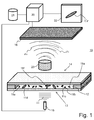
- the figure 1 illustrates a device 10 for observing a particle 11a-11f present in a sample 12.
- the sample 12 is disposed between a light source 15, spatially and temporally coherent (eg a laser) or pseudo-coherent (eg a light-emitting diode , a laser diode), and a sensitive digital sensor 16 in the spectral range of the light source.
- the light source 15 has a small spectral width, for example less than 200 nm, less than 100 nm or even less than 25 nm.
- the light source 15 emits a coherent signal Sn oriented on a first face 13 of the sample, for example conveyed by a waveguide such as an optical fiber.
- the sample 12 consists of a liquid such as water, a buffer solution, a culture medium or a reactive medium (comprising or not an antibiotic), in which are the particles 11a-11f to be observed.
- the sample 12 may be in the form of a solid, preferably translucent, medium, such as agar agar, in which the particles 11a-11f are located.
- Sample 12 may also be a gaseous medium. The particles 11a-11f can be located inside the medium or on the surface of the sample 12.
- the particles 11a-11f may be microorganisms such as bacteria, fungi or yeasts. It can also be cells, multicellular organisms, or any other particle of pollutant particle type, dust.
- the size of the particles 11a-11f observed varies between 500 nm and several hundred microns, or even a few millimeters.
- the sample 12 is contained in an analysis chamber, delimited vertically by a lower blade and an upper blade, for example conventional microscope slides.
- the analysis chamber is delimited laterally by an adhesive or by any other impervious material.
- the lower and upper blades are transparent to the wavelength of the light source 15, the sample and the chamber passing for example more than 50% of the wavelength of the light source at normal incidence on the lower blade.
- the particles 11a-11f are disposed in the sample 12 at the level of the upper blade.
- the lower face of the upper plate comprises, for this purpose, ligands allowing the particles to be hooked, for example polycations (eg poly-L-lysine) in the context of microorganisms.
- polycations eg poly-L-lysine
- the particles 11a-11f can nevertheless move in the sample 12.
- the device comprises an optical system 23 consisting of, for example, a microscope objective and a tube lens, disposed in the air and at a fixed distance from the sample.
- the optical system 23 is optionally equipped with a filter that can be located in front of the objective or between the objective and the tube lens.
- the optical system 23 is characterized by its optical axis, its object plane, also called the focusing plane, at a distance from the objective, and its image plane, conjugated from the object plane by the optical system .
- object plane also called the focusing plane
- image plane conjugated from the object plane by the optical system .
- the optical properties of the system 23 are fixed (eg optics with fixed focal length).
- the object and image planes are orthogonal to the optical axis.
- the image sensor 16 is located, facing a second face 14 of the sample, in the focal plane or near the latter.
- the sensor for example a CCD or CMOS sensor, comprises a periodic two-dimensional network of sensitive elementary sites, and a proximity electronics which regulates the exposure time and the zeroing of the sites, in a manner known per se.
- the output signal of an elementary site is a function of the amount of radiation of the incident spectral range at said site during the exposure time. This signal is then converted, for example by the proximity electronics, into an image point, or "pixel", of a digital image.
- the sensor thus produces a digital image in the form of a matrix with C columns and L lines.
- Each pixel of this matrix corresponds in a manner known per se at a position of Cartesian coordinates ( x ( c, l ), y ( c, l ))) in the focal plane of the optical system 23, for example the position of the center of the elementary sensitive shape site. rectangular.
- the step and the filling factor of the periodic grating are chosen to respect the Shannon-Nyquist criterion with respect to the size of the particles observed, so as to define at least two pixels per particle.
- the image sensor 16 acquires a transmission image of the sample in the spectral range of the light source.
- the image Ih acquired by the image sensor 16 comprises holographic information insofar as it results from the interference between a wave Fi diffracted by the particles 11a-11f and a reference wave Fn having passed through the sample without having interacted with him.
- the digital image Ih acquired and stored in the unit 20 is an intensity image, the phase information being thus coded here.
- the coherent signal Sn coming from the light source 15 into two components, for example by means of a semi-transparent plate.
- the first component serves as a reference wave and the second component is diffracted by the sample 12, the image in the image plane of the optical system 23 resulting from the interference between the diffracted wave and the reference wave.
- the intensity image Ih acquired by the image sensor 16 is not focused on the particle to be observed and obtaining information focused on the particle is obtained numerically by a processing unit 20 connected to the image sensor. image 16 to receive the images acquired by the latter.
- defocused is meant here that there is no intersection between the focus plane and the object particle of the observation.
- the processing unit 20 may correspond to a computer, a microcontroller, a touch pad or a smart phone, or generally any processor-based computer system capable of receiving data, process this data by implementing computer instructions stored in a computer memory, and to deliver and / or store in a computer memory the result of the treatment.
- the processing unit 20 may be wired or wirelessly connected to the image sensor 16 or by means of wireless communication.
- the unit may be associated with a screen for displaying the intermediate or final results of the method of the invention.
- the Figure 2 illustrates the computer processing modules 51-53, integrated in the processing unit 20 in the form of computer instructions implemented by the computer, following the acquisition of the image 50 in intensity Ih by the sensor of picture 16.
- a first module 51 constructs a series of complex matrices I 1 , ..., In , ..., IN , called " EM electromagnetic matrices" , modeling from the image Ih the light wave front propagated along the optical axis for a plurality of deviations from the focusing plane of the optical system 23, and in particular deviations positioned in the sample.
- the processing unit 20 stores a single wave number, which is common for all the media involved, for example the index of air.
- the unit 20 stores the refractive indices of the various media at play on the along the optical axis and builds the matrices I 1 - IN step by step to take into account the phenomena at the interfaces.
- the sampling step in z is preferably less than one tenth of the thickness of the bacterium, for example less than 0.1 microns, and preferably less than 0.03 microns.
- the processing unit 20 then calculates on each matrix In a positive surjective application AS of the complex space VS VS ⁇ The to real space R VS ⁇
- AS in AS at 1 1 z not ... AS at vs 1 z not ... AS at VS 1 z not ⁇ ⁇ ⁇ ... ⁇ AS at 1 l z not ... AS at vs l z not ... AS at ( VS l z not ⁇ ⁇ ⁇ ⁇ AS at The 1 z not ... AS at vs The z not ... AS at VS The z not
- the unit 20 calculates the Hermitian norm (or its square) of the components a ( c , l ) zn , the absolute value or the square of the imaginary part (denoted Im ( a ( c, l ) zn ) or of the real part (denoted Re ( a ( c, l ) zn )) of the components a ( c, 1 ) zn , or Re 2 ( a ( c, 1 ) zn ) + Im 2 ( a ( c, 1 ) zn ) or ( Re 2 ( a ( c, 1) zn ) + Im 2 ( a ( c, 1 ) zn ) 1/2 .
- the AS ( I 1) - AS ( IN ) matrices do not necessarily represent a luminous intensity, but the inventors have noted their resemblance to intensity images obtained under non-coherent illumination.
- the particles are represented, as in a photograph, in their particle form.
- the matrices AS ( I 1) - AS ( IN ) are denoted I 1 - IN, and the notation a ( c , l ) zn corresponding to AS ( a ( c, l ) zn ) .
- the method according to the invention then consists in identifying particles in the sample as a function of the matrices I 1 -IN, and for each identified particle, determining an optimal focusing distance z , ie of focusing, for this particle, then to determine in the matrix of the series I 1 - IN corresponding to this distance, a set of pixels belonging to this particle.
- the second module 52 aims to determine an average focusing distance zfmoy from the series of matrices I 1 - IN and to select in this series the matrix, denoted Ifmoy, whose distance z is equal to or closest to the distance zfmoy .
- the unit 20 recalculates the Ifmoy matrix for the distance zfmoy.
- This average focusing distance zfmoy is that which best corresponds to the ideal focusing conditions on all the particles 11a-11f in the sense of a predetermined focusing criterion. This distance can be determined by all the known techniques of signal processing or the field of photography, for example autofocus.
- the resulting Ifmoy electromagnetic matrix is sufficiently "focused" for particles at different depths to be detected in the Ifmoy matrix .
- the particles detected are in particular those included in a sample depth equal to the depth of field.
- the particles are arranged in a volume of thickness close to or equal to this depth of field, so that the all, or almost all, of the sample particles can be detected in the Ifmoy matrix .
- the figure 3 illustrates an example of determining the average focusing distance zfmoy by representing, for each coordinate ( c , l ) , the variation of a ( c , l ) zn as a function of the distance z in the image stack I 1 - IN .
- a particle is located in the sample along the axis, parallel to the optical axis of the system 23, with a coordinate (c, 1) in the focal plane, a variation of a ( c , 1 ) zn is observed .
- the representation at 55 of the variations a ( c , l ) zn is analogous to a Gaussian function as a function of the distance z.
- the unit 20 selects the P coordinates, for example the 10000 coordinates, exhibiting the largest variations of their values a ( c , l ) zn as a function of z (eg having the largest differences between the maximum value and the minimum value), then calculates the distance zfmoy on these P coordinates, which increases the accuracy over this distance.
- the values a ( c , l ) zn of these P coordinates are averaged and the optimum of the averaged curve as a function of z is calculated, the distance z of the optimum being the distance zfmoy
- the processing unit 20 comprises a module 53 for identifying the particles and a module 54 for determining an optimum focusing distance for each identified particle and for determining the pixels of the particle for this distance.
- the module 53 for identifying the particles in the Ifmoy matrix may take several forms of image segmentation of the state of the art, such as scanning this matrix until it detects the contours of a finite element.
- the unit 20 applies prior thresholding to the Ifmoy matrix , the threshold value being for example equal to Moy ( Ifmoy) + p ⁇ E ( Ifmoy ), where Moy ( Ifmoy ) is the average of the pixels of the Ifmoy matrix , E ( Ifmoy ) is their standard deviation, and p an integer greater than 1, for example equal to 6 Values greater than this threshold are then determined as belonging to particles, and an image segmentation on the thresholded matrix is Implementation.
- the method determines, at 54, for each set of coordinates Part_i, which distance z offers the best focusing for the corresponding particle, then determines which matrix of the series I 1 - IN corresponds to this distance (or calculates a new image for this distance), and finally memorizes in a set Ri the pixels of the selected matrix that correspond to the coordinates listed in the set Part _ i .
- the figure 4 illustrates an example of determining a set R i.
- This determination begins, at 58, by the calculation of the optimal focusing distance zfopt_i, for example in a similar manner to the calculation of the average focusing distance. For example, for each coordinate (c, l) of the set Part_i, the distance corresponding to the optimum of a ( c , l ) zn is calculated, then the optimal focusing distance zfopt_i is chosen equal to the average of the distances z calculated.
- the values a ( c , l ) zn of the set Part_i are averaged, and the optimum of the curve of the averaged values as a function of z is calculated, the distance z of the optimum being the distance zfopt_i.
- the matrix of the series I 1 - IN corresponding to the distance zfopt_i, denoted I_i is selected.
- the pixels of the selected matrix of coordinates listed in the set Part _ i are selected and stored in a set Ri.
- Figures 3 and 4 are easily combinable because they use the same Gaussian functions.
- the treatments can therefore be performed in parallel so as to limit the calculation time.
- the computation time can also be reduced by sub-sampling (eg: z at a period of 0.1 ⁇ m) the matrices of the matrix stack I 1 - IN for selecting the set Ri .
- an image Ifp- i is preferably displayed on a screen 22.
- This image is for example a rectangular window of the matrix I_i comprising the pixels Ri.
- a rod-shaped bacterium is effectively rod-shaped in the focused matrix I_i.
- a practitioner can thus observe the shape of the particle 11a-11f very quickly without performing manipulation on the optical system 23. To improve the analysis of the particle 11a-11f, it can be represented over time through several successive acquisitions.
- the set Ri when it is obtained, it is stored in a memory 21 connected to the processing unit 20. After a predefined duration, a new set Ri is searched by means of a new image acquisition. Ih, the time step being less than or equal to 5 minutes in the context of bacteria, and preferably less than or equal to 1 minute.
- the time step being less than or equal to 5 minutes in the context of bacteria, and preferably less than or equal to 1 minute.
- the inventors have noted through their invention that this period makes it possible to follow the phenotypic or morphological modifications of any type of bacterium. Indeed, we observe, by the simple visual inspection of a time series of images Ifp_i of a bacterium, that some bacteria change from one minute to another.
- the new set Ri must correspond to the same particle 11a-11f as the first set Ri.
- the module 53 for determining sets Part_ 1 - Part_N is made according to the position and / or the shape of a particle 11a-11f selected on a previous Ifmoy matrix.
- the focussed Ri sets Ifp- i are all stored in the memory 21 and the screen 22 allows the practitioner to launch a focused image stream Ifp- i on a particle 11a-11f so as to analyze its behavior.
- the device can also perform the analysis of several samples 12 simultaneously, for example to perform an antibiogram of a bacterium.
- the processing unit 20 can be connected to several image sensors 16 associated with several samples 12. The processing unit 20 then performs the processing of several images Ih from several image sensors 16 and the screen 22 illustrates the Ifp focused images .
- the optimal focal length zfopt_i corresponds to an average focusing on the particle, usually leading to a focus on a median plane of the particle. This makes it possible to compare the sets Ri between several instants of acquisition. As a variant, a focus is sought for each pixel (eg calculation of the distance corresponding to the optimal of a ( c , 1 ) zn as a function of z , search for the electromagnetic matrix at this distance, storage in the set Ri of pixel of this coordinate matrix (c, l)), which allows to build a 3D visualization of the particle. On the other hand, the comparison between two successive reconstructions of the particle is more difficult.
- the acquisition according to the invention being carried out without focus, it is possible to acquire at a very high frequency, and if necessary to do the treatment after having acquired.
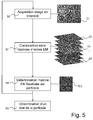
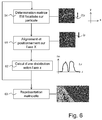
- the figure 5 illustrates a second embodiment of the invention to detect the division of a microorganism as a function of time.
- the processing unit 20 comprises a module 60 for determining a state of the particle 11a-11f as a function of the temporal evolution of the set of pixels Ri associated with the microorganism, eg the state phenotype or morphology of a bacterium.
- the determination 54 of the set of pixels Ri can be performed by a simple search for digital focusing from the image stack I 1 - IN contrary to the embodiment of the figure 2 in which a double focus search is performed.
- the pixels of the set Ri are then those of the Ifmoy matrix .
- the determination 54 of the set of pixels R 1 can be carried out with a process similar to that of the figure 2 .
- the determination module 60 of a state of the particle 11a-11f can implement different indicators and treatments.
- the state of the particle 11a-11f can be analyzed according to the state of its division cycle, its morphological characteristics, its physiological characteristics or a combination of several indicators.
- the indicators are defined according to the nature of the particle 11a-11f whose state is sought.
- images of intensity Ih are acquired periodically, advantageously every minute for the reasons described above, and for each image Ih acquired, the set Ri associated with the bacterium is determined
- a rotation 61 is applied to the set Ri so as to align and position the particle 11a-11f on a predefined constant axis in time, for example by aligning the particle to the left on the x- axis of the abscissae (ie the axis corresponding to the lines of the images acquired).
- the aligned set Ri is then projected onto the alignment axis, for example by averaging the pixels on each ordinate y (ie the column axis of the acquired images).
- the distribution Ip thus obtained is represented 62 in the form of a distribution of the sum Im per column as a function of the position of the ordinate x of the pixels, and is for example stored in the unit 20 in the form of a line vector.
- Dist_Q IP_ 1 ⁇ Ip_q ⁇ Ip_Q
- the matrix representation thus obtained is particularly effective in determining the state of the particle 11a-11f.
- this matrix representation makes it possible to observe the elongation of a particle or the presence of at least one cell division.
- a simple thresholding on the form of the matrix representation then makes it possible to define whether an antibiotic has acted efficiently or not on a bacterium.
- the thresholded matrix composed of zero and one, a block of zeros framed by two blocks of 1, the appearance of the block of zeros marking the start time of division, and increase.
- the identification by the treatment unit 20 of the appearance of such a block thus makes it possible to identify in a simple manner the division of the bacterium.
- further analyzes may be performed by modeling the rate of displacement of a particle 11a-11f between the holographic images Ih picked up by the image sensor 16 or by analyzing the structural characteristics of a particle 11a-11f by correspondence with particles of known form.
- the invention thus makes it possible to obtain an accurate image of a particle 11a-11f present in a sample 12.
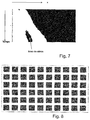
- the invention has made it possible to obtain an image representing a bacterium with a number of pixels of between 100 and 400 pixels. . It follows that it is possible visually or numerically to visualize, without marking (eg fluorescent), the contents of a microorganism. In particular, we can observe the distribution of intracellular material in a bacterium. Without being bound to the theory, the inventors were able to observe the appearance of two poles in a bacterium before its division, which could correspond to the meiosis of a bacterium, as illustrated on the figure 8 which represents, as a function of time, the evolution of a bacterium.
- the processing unit 20 uses, over time, a treatment of the set Ri of a bacterium, or the distribution Ip_q, in order to determine the appearance of two zones of similar value. A division of the bacterium is thus predicted well before this division takes place.
- the figure 9 illustrates the Ip_q distributions of the bacterium illustrated in figure 8 . As can be seen in this figure, when the bacterium prepares for division, there appear two poles in the distribution, well before the division itself which results in two distinct portions of the distribution.
- the processing unit 20 is for example configured to detect the appearance of two poles in the distribution and to predict, based on this detection, the division of the bacterium, and consequently its susceptibility to the antibiotic present in the sample.
- the invention also makes it possible to obtain the evolution of the particle 11a-11f over time in order to visualize its behavior, for example its speed of movement or its process of cell division.
- the resolution obtained by the invention (several hundred pixels per bacterium for a system designed by the inventors), it is possible to observe the influence of an antibiotic on the morphology and the intracellular content of the bacteria.
- the high rate of acquisition of the invention makes it possible to track very temporally variations of the bacterium (e.g. growth, division, reaction to a culture medium, a medium with antibiotic, etc.).
Abstract
L'invention concerne un dispositif d'acquisition (10) de particules (11a-11f) présentes dans un échantillon (12), ledit dispositif d'acquisition comportant une source lumineuse (15) spatialement cohérente, une optique et un capteur d'image (16) placé dans le plan focal de l'optique et configuré pour capturer une image en intensité, et une unité informatique configurée pour : - construire une série de matrice électromagnétique de propagation obtenues pour une pluralité d'écarts de défocalisation par rapport à un plan de mise au point de l'optique ; - déterminer une première matrice électromagnétique de focalisée moyenne sur les particules à partir de la série de matrices électromagnétique, - identifier au moins une des particules dans la première matrice électromagnétique et de mémorisation des coordonnées de ladite particule ; et - déterminer une seconde matrice électromagnétique à une distance de mise au point sur une particule identifiée à partir des composantes de la série de matrices électromagnétique ayant les coordonnées mémorisées.The invention relates to an acquisition device (10) for particles (11a-11f) present in a sample (12), said acquisition device comprising a spatially coherent light source (15), an optical element and an image sensor. (16) placed in the focal plane of the optics and configured to capture an intensity image, and a computer unit configured to: constructing a series of electromagnetic propagation matrices obtained for a plurality of defocusing deviations from an optical focusing plane; determining a first average focused electromagnetic matrix on the particles from the series of electromagnetic matrices, identifying at least one of the particles in the first electromagnetic matrix and storing the coordinates of said particle; and determining a second electromagnetic matrix at a focusing distance on a particle identified from the components of the series of electromagnetic matrices having the stored coordinates.
Description
La présente invention concerne le domaine de l'acquisition optique de particules biologiques. Les particules biologiques peuvent être des microorganismes tels que des bactéries, des champignons ou des levures par exemple. Il peut également s'agir de cellules, organismes multicellulaires, ou toute autre particule de type particule polluante, poussière.The present invention relates to the field of optical acquisition of biological particles. The biological particles may be microorganisms such as bacteria, fungi or yeasts, for example. It can also be cells, multicellular organisms, or any other particle of pollutant particle type, dust.
L'invention trouve une application particulièrement avantageuse pour analyser l'état d'une particule biologique, par exemple pour savoir l'état métabolique d'une bactérie suite à l'application d'un antibiotique. L'invention permet, par exemple, de réaliser un antibiogramme d'une bactérie.The invention finds a particularly advantageous application for analyzing the state of a biological particle, for example to know the metabolic state of a bacterium following the application of an antibiotic. The invention makes it possible, for example, to perform an antibiogram of a bacterium.
Un antibiogramme est une technique de laboratoire visant à tester le phénotype d'une souche bactérienne vis-à-vis d'un ou plusieurs antibiotiques. Un antibiogramme est classiquement réalisé par culture d'un échantillon contenant des bactéries et un antibiotique.An antibiogram is a laboratory technique to test the phenotype of a bacterial strain against one or more antibiotics. An antibiogram is conventionally performed by culturing a sample containing bacteria and an antibiotic.
La demande de brevet
Cependant, le processus de marquage est particulièrement long et complexe à réaliser et ces marqueurs chimiques ont un effet cytotoxique sur les bactéries. Il s'ensuit que ce mode de visualisation ne permet pas d'observer les bactéries à plusieurs instants de la culture des bactéries.However, the labeling process is particularly long and complex to perform and these chemical markers have a cytotoxic effect on the bacteria. It follows that this mode of visualization does not make it possible to observe the bacteria at several moments of the culture of the bacteria.
Il est donc nécessaire d'utiliser un temps de culture suffisamment long, de l'ordre de 24 à 72 heures, pour garantir la fiabilité de la mesure.It is therefore necessary to use a sufficiently long culture time, of the order of 24 to 72 hours, to guarantee the reliability of the measurement.
D'autres méthodes de visualisation de particules biologiques utilisent un microscope, permettant une mesure non destructive d'un échantillon.Other biological particle visualization methods use a microscope, allowing non-destructive measurement of a sample.
La microscopie holographique numérique ou DHM (Digital Holographie Microscopy) est une technique d'imagerie permettant de s'affranchir des contraintes de profondeur de champ de la microscopie optique classique. Schématiquement, elle consiste à enregistrer un hologramme formé par l'interférence entre les ondes lumineuses diffractées par l'objet observé et une onde de référence présentant une cohérence spatiale. Cette technique est décrite dans l'article de revue de
Récemment, il a été proposé d'utiliser la microscopie holographique numérique pour identifier des micro-organismes de manière automatisée. Ainsi, l'article de
De manière similaire, l'article de
Les méthodes d'identification précitées sont toutefois complexes dans la mesure où elles nécessitent une focalisation dans des plans successifs de mise au point.The aforementioned identification methods are however complex insofar as they require focusing in successive planes of focus.
A contrario, la focalisation dans un seul plan de mise au point, autrement dit à une seule profondeur d'analyse, ne suffit généralement pas à identifier un type de microorganisme avec un faible taux de fausse détection.On the other hand, focusing in a single focus plane, in other words at a single depth of analysis, is generally not sufficient to identify a type of microorganism with a low rate of false detection.
Le problème technique objectif de la présente invention est, par conséquent, d'observer une particule biologique en limitant le temps d'acquisition, c'est-à-dire sans marquage et sans une mise au point précise du système optique.The objective technical problem of the present invention is, therefore, to observe a biological particle by limiting the acquisition time, that is to say without marking and without precise focusing of the optical system.
Pour ressoude le problème technique, l'invention propose un dispositif d'acquisition d'une particule intégrant une simple acquisition sans focalisation associée à une reconstruction numérique de la focalisation comportant : une première focalisation moyenne destinée à détecter au moins une particule et une seconde focalisation spécifique d'une région d'intérêt contenant la particule.To solve the technical problem, the invention proposes a device for acquiring a particle integrating a simple acquisition without focusing associated with a digital reconstruction of the focusing comprising: a first average focusing for detecting at least one particle and a second focusing specific of a region of interest containing the particle.
A cet effet, selon un premier aspect, l'invention concerne un dispositif d'acquisition d'une pluralité de particules présentes dans un échantillon, ledit dispositif d'acquisition comportant :
- une source lumineuse, spatialement cohérente ou pseudo-cohérente, orientée sur une première face dudit échantillon ;
- un système optique ayant un axe optique et réalisant la conjugaison entre un plan de mise au point et un plan focal, orienté sur une seconde face dudit échantillon opposé à ladite première face, et placé par rapport à l'échantillon de sorte que les particules ne sont pas dans le plan de mis au point ;
- un capteur d'image, placé dans le plan focal du système optique et configuré pour acquérir une image en intensité formée par l'interférence entre ladite source lumineuse et ledit échantillon ; et
- une unité de traitement informatique comportant :
- o un module de construction numérique d'une série de matrices électromagnétiques modélisant, à partir de l'image acquise, l'onde électromagnétique dans des plans parallèles au plan de mise au point et compris dans l'échantillon pour une pluralité d'écarts par rapport audit plan ;
- o un module de détermination d'une première matrice électromagnétique à une distance de mise au point moyenne sur les particules à partir de la série de matrices électromagnétiques ;
- o un module d'identification d'au moins une des particules dans la première matrice électromagnétique et de mémorisation des coordonnées de ladite particule ; et
- o un module de détermination d'une seconde matrice électromagnétique à une distance de mise au point sur une particule identifiée à partir des composantes de la série de matrices électromagnétique ayant les coordonnées mémorisées.
- a light source, spatially coherent or pseudo-coherent, oriented on a first face of said sample;
- an optical system having an optical axis and realizing the conjugation between a focusing plane and a focal plane, oriented on a second face of said sample opposite to said first face, and placed with respect to the sample so that the particles do not are not in the plan of focus;
- an image sensor, placed in the focal plane of the optical system and configured to acquire an intensity image formed by the interference between said light source and said sample; and
- a computer processing unit comprising:
- a digital construction module of a series of electromagnetic matrices modeling, from the acquired image, the electromagnetic wave in planes parallel to the focusing plane and included in the sample for a plurality of deviations by report to said plan;
- a module for determining a first electromagnetic matrix at an average focusing distance on the particles from the series of electromagnetic matrices;
- a module for identifying at least one of the particles in the first electromagnetic matrix and for memorizing the coordinates of said particle; and
- a module for determining a second electromagnetic matrix at a focusing distance on a particle identified from the components of the series of electromagnetic matrices having the memorized coordinates.
L'invention permet ainsi d'observer des phénomènes similaires à ceux décrits dans l'état de l'art sans marquage chimique. La mise au point est effectuée de manière numérique à partir d'une image défocalisée associée à une reconstruction numérique de la focalisation comportant : une première focalisation moyenne destinée à détecter au moins une particule et une seconde focalisation spécifique d'une région d'intérêt contenant la particule.The invention thus makes it possible to observe phenomena similar to those described in the state of the art without chemical marking. The focusing is carried out digitally from a defocused image associated with a digital reconstruction of the focusing comprising: a first average focusing for detecting at least one particle and a second specific focusing of a region of interest containing the particle.
Il s'ensuit que les instruments de mesure sont simplifiés car il n'est pas nécessaire d'utiliser des appareils de mise au point extrêmement précis permettant de mettre au point une image de quelques nanomètres. Le temps d'acquisition est également réduit car la mise au point ou le marquage n'est plus nécessaire.It follows that the measuring instruments are simplified because it is not necessary to use extremely precise focusing devices to develop an image of a few nanometers. The acquisition time is also reduced because the focus or the marking is no longer necessary.
En outre, les opérations de marquage et de mise au point sont classiquement réalisées manuellement. L'invention permet également de limiter ces interactions manuelles durant l'acquisition et donc d'automatiser le processus d'acquisition d'une particule. Il s'ensuit que le dispositif d'acquisition d'une particule présente dans un échantillon peut être positionné au plus près d'un patient de sorte à améliorer la rapidité de traitement d'un patient.In addition, the marking and debugging operations are conventionally performed manually. The invention also makes it possible to limit these manual interactions during the acquisition and thus to automate the process of acquiring a particle. It follows that the device for acquiring a particle present in a sample can be positioned closer to a patient so as to improve the speed of treatment of a patient.
Le processus classique pour déterminer les antibiotiques efficaces sur une souche bactérienne consiste à réaliser un prélèvent contenant ladite souche (e.g. sur un patient, un animal, un lot alimentaire,...) puis à transmettre le prélèvement à un centre d'analyse. Lorsque le centre d'analyse réceptionne le prélèvement, il procède tout d'abord à la culture de la souche bactérienne pour obtenir au moins une colonie de celle-ci, culture comprise entre 24 heure et 72 heures. Il prépare ensuite à partir de cette colonie plusieurs échantillons comprenant des antibiotiques différents et/ou des concentrations d'antibiotiques différentes, puis met à nouveau les échantillons à incuber. Après une nouvelle durée de culture comprise également entre 24 et 72 heures, chaque échantillon est analysé manuellement pour déterminer si l'antibiotique a agi efficacement. Les résultats sont alors retransmis au praticien pour appliquer l'antibiotique et/ou la concentration d'antibiotique le plus efficace. L'invention permet de refondre entièrement ce processus en déplaçant le dispositif d'analyse proche du praticien car la manipulation subtile d'un opérateur n'est plus nécessaire pour effectuer la mise au point ou le marquage.The traditional process for determining the effective antibiotics on a bacterial strain is to make a sample containing said strain (e.g. on a patient, an animal, a food lot, ...) and then to transmit the sample to a center of analysis. When the analysis center receives the sample, it first proceeds to the culture of the bacterial strain to obtain at least one colony thereof, culture between 24 hours and 72 hours. He then prepares from this colony several samples comprising different antibiotics and / or different antibiotic concentrations, and then again samples to be incubated. After a further culture period of 24 to 72 hours, each sample is analyzed manually to determine if the antibiotic has been effective. The results are then relayed to the practitioner to apply the antibiotic and / or the most effective antibiotic concentration. The invention makes it possible to completely recast this process by moving the analysis device close to the practitioner because the subtle manipulation of an operator is no longer necessary to perform the development or marking.
Typiquement, l'invention a permis de détecter les modifications structurelles d'une bactérie en présence d'un antibiotique après une incubation de seulement une dizaine de minute, et sa sensibilité au bout de deux heures (détection de la présence ou de l'absence d'une division ou d'un motif codant la division) contrairement au processus précédemment décrit qui peut prendre plusieurs jours. En effet, les mesures étant non destructives, il est possible de réaliser des analyses très tôt dans le processus de culture sans risquer de détruire l'échantillon et donc de prolonger le temps d'analyse.Typically, the invention has made it possible to detect the structural modifications of a bacterium in the presence of an antibiotic after an incubation of only about ten minutes, and its sensitivity after two hours (detection of the presence or absence a division or a pattern coding division) unlike the previously described process which may take several days. Since the measurements are non-destructive, it is possible to carry out analyzes very early in the culture process without the risk of destroying the sample and thus prolonging the analysis time.
Selon un mode de réalisation, ledit capteur d'image est configuré pour acquérir un flux d'images, et l'unité de traitement est configurée pour suivre une particule dans le flux de premières matrices électromagnétiques.According to one embodiment, said image sensor is configured to acquire a stream of images, and the processing unit is configured to follow a particle in the stream of first electromagnetic matrices.
Ce mode de réalisation permet de suivre une particule sur plusieurs images successives de sorte à former un film représentant l'évolution d'une particule au cours du temps. La méthode classique du marquage chimique ne permet pas de représenter l'évolution d'une particule au cours du temps car les particules sont altérées après la première analyse.This embodiment makes it possible to follow a particle over several successive images so as to form a film representing the evolution of a particle over time. The classical method of chemical labeling does not allow to represent the evolution of a particle over time because the particles are altered after the first analysis.
La méthode classique de visualisation de particules biologiques utilisant la microscopie classique (non holographique) permet de représenter une particule au cours du temps mais elle nécessite une focalisation manuelle pour chaque image. En effet, une particule n'est pas fixe dans un échantillon et elle peut se déplacer dans le plan du support ou dans la profondeur de l'échantillon. Même si une particule se déplace uniquement dans le plan de son support, la focalisation de la particule peut être défaillante entre deux images en raison d'un défaut de planéité du support.The classical method of visualization of biological particles using conventional (non-holographic) microscopy makes it possible to represent a particle over time, but it requires manual focusing for each image. Indeed, a particle is not fixed in a sample and can move in the plane of the support or in the depth of the sample. Even if a particle moves only in the plane of its support, the focusing of the particle can be defective between two images because of a lack of flatness of the support.
Ce mode de réalisation permet de représenter une particule au cours du temps en recherchant une focalisation pouvant varier selon le plan du support ou dans la profondeur de l'échantillon. Avantageusement les particules sont des microorganismes, et la durée entre deux images acquises issues dudit capteur d'image est inférieure ou égale à 1 minute.This embodiment makes it possible to represent a particle over time by searching for a focus that can vary according to the plane of the support or in the depth of the sample. Advantageously, the particles are microorganisms, and the duration between two images acquired from said image sensor is less than or equal to 1 minute.
Typiquement, ce mode de réalisation de l'invention a permis d'observer la division cellulaire d'une bactérie.Typically, this embodiment of the invention has made it possible to observe the cell division of a bacterium.
Il s'ensuit que ce mode de réalisation permet d'augmenter la fiabilité et la rapidité d'analyse de l'état d'une particule. En effet, au lieu d'analyser une particule uniquement en fonction de ses caractéristiques physiologique, il est possible d'étudier une particule en fonction de son comportement. Par exemple, il est possible de constater qu'une bactérie ne se divise plus lorsqu'un antibiotique efficace est présent dans l'échantillon.It follows that this embodiment makes it possible to increase the reliability and the speed of analysis of the state of a particle. Indeed, instead of analyzing a particle only according to its physiological characteristics, it is possible to study a particle according to its behavior. For example, it can be seen that a bacterium no longer divides when an effective antibiotic is present in the sample.
Selon un mode de réalisation, ladite série de matrices électromagnétiques est obtenue par un modèle de propagation numérique d'une lumière à travers ledit échantillon, les matrices électromagnétiques variant en modulant une distance d'un axe optique dudit modèle de propagation. Ce mode de réalisation permet de reconstruire efficacement l'image de la particule.According to one embodiment, said series of electromagnetic matrices is obtained by a digital propagation model of a light through said sample, the electromagnetic matrices varying by modulating a distance from an optical axis of said propagation model. This embodiment makes it possible to efficiently reconstruct the image of the particle.
Avantageusement, l'unité de traitement comprend un module de transformation des matrices électromagnétiques issues du modèle de propagation par une application surjective de l'espace complexe dans l'espace réel. Les matrices obtenues permettent une visualisation directement compréhensible par un opérateur ainsi que la mise en oeuvre de traitement d'image classique sur la base par exemple de la morphologie des particules.Advantageously, the processing unit comprises a module for transforming electromagnetic matrices derived from the propagation model by a surjective application of the complex space in real space. The matrices obtained allow a visualization directly understandable by an operator as well as the implementation of conventional image processing on the basis of, for example, the morphology of the particles.
Selon un mode de réalisation, la première matrice électromagnétique est obtenue en représentant, à chaque coordonnée, les composantes à ladite coordonnée des matrices électromagnétiques en fonction de ladite distance dudit axe optique, et en recherchant une moyenne des maxima de toutes les représentations. Ce mode de réalisation permet de détecter efficacement la matrice focalisée moyenne.According to one embodiment, the first electromagnetic matrix is obtained by representing, at each coordinate, the components at said coordinate of the electromagnetic matrices as a function of said distance from said optical axis, and looking for an average of the maxima of all the representations. This embodiment makes it possible to effectively detect the average focused matrix.
Selon un mode de réalisation, la seconde image électromagnétique est obtenue en représentant, à chaque coordonnée de la particule identifiée, les composantes à ladite coordonnée des matrices électromagnétiques en fonction de ladite distance dudit axe optique, et en recherchant une moyenne des maxima de toutes les représentations. Ce mode de réalisation permet de détecter efficacement la matrice focalisée sur la particule.According to one embodiment, the second electromagnetic image is obtained by representing, at each coordinate of the identified particle, the components at said coordinate of the electromagnetic matrices as a function of said distance from said optical axis, and looking for an average of the maxima of all the representations. This embodiment makes it possible to effectively detect the matrix focused on the particle.
Selon un mode de réalisation, les matrices de ladite série de matrices électromagnétiques utilisées pour déterminer ladite première matrice électromagnétique et/ou pour déterminer ladite seconde matrice électromagnétique sont sous-échantillonnées selon ladite distance. Ce mode de réalisation permet de limiter le temps de calcul nécessaire pour les focalisations.According to one embodiment, the matrices of said series of electromagnetic matrices used to determine said first electromagnetic matrix and / or to determine said second electromagnetic matrix are subsampled according to said distance. This embodiment makes it possible to limit the computation time necessary for focusing.
Selon un mode de réalisation, ledit dispositif comporte plusieurs unités d'acquisition, chaque unité d'acquisition comportant un capteur d'image et des moyens de focalisation spécifiques, ledit dispositif étant configuré pour représenter une image d'une particule de chaque échantillon. Ce mode de réalisation permet de faire des comparaisons rapides entre plusieurs échantillons, par exemple pour réaliser un antibiogramme.According to one embodiment, said device comprises several acquisition units, each acquisition unit comprising an image sensor and specific focusing means, said device being configured to represent an image of a particle of each sample. This embodiment makes it possible to make rapid comparisons between several samples, for example to perform an antibiogram.
Ce premier aspect de l'invention peut également être formulé sous la forme d'un procédé d'acquisition d'une pluralité de particules présentes dans un échantillon, ledit procédé d'acquisition comportant les étapes suivantes :
- émission d'une source lumineuse, spatialement cohérente ou pseudo-cohérente, orientée sur une première face dudit échantillon ;
- acquisition à l'aide d'un capteur d'image d'une image en intensité, ledit capteur étant placé dans le plan focal d'un système optique ayant un axe optique et réalisant la conjugaison entre un plan de mise au point et le plan focal, orienté sur une seconde face dudit échantillon opposé à ladite première face, et placé par rapport à l'échantillon de sorte que la particule n'est pas dans le plan de mis au point, l'image étant formée par interférence entre ladite source lumineuse et ledit échantillon ;
- construction numérique d'une série de matrices électromagnétiques modélisant, à partir de l'image acquise, l'onde électromagnétique dans des plans parallèles au plan de mise au point et compris dans l'échantillon pour une pluralité d'écarts par rapport audit plan ;
- identification d'au moins une des particules dans la première matrice électromagnétique et mémorisation des coordonnées de ladite particule ; et
- détermination d'une seconde matrice électromagnétique à une distance de mise au point sur une particule identifiée à partir des composantes de la série de matrices électromagnétique ayant les coordonnées mémorisées.
- emission of a light source, spatially coherent or pseudo-coherent, oriented on a first face of said sample;
- acquisition using an image sensor of an intensity image, said sensor being placed in the focal plane of an optical system having an optical axis and performing the conjugation between a focusing plane and the plane focal, oriented a second face of said sample opposite to said first face, and placed relative to the sample so that the particle is not in the focusing plane, the image being formed by interference between said light source and said sample ;
- digital construction of a series of electromagnetic matrices modeling, from the acquired image, the electromagnetic wave in planes parallel to the focusing plane and included in the sample for a plurality of deviations from said plane;
- identifying at least one of the particles in the first electromagnetic matrix and storing the coordinates of said particle; and
- determining a second electromagnetic matrix at a focusing distance on a particle identified from the components of the series of electromagnetic matrices having the stored coordinates.
Selon un second aspect, l'invention a également pour objet un procédé d'analyse d'au moins une particule présente dans un échantillon, ledit procédé d'analyse comportant les étapes suivantes :
- émission d'une source lumineuse, spatialement cohérente ou pseudo-cohérente, orientée sur une première face dudit échantillon ;
- acquisition à l'aide d'un capteur d'image d'une image en intensité, ledit capteur étant placé dans le plan focal d'un système optique ayant un axe optique et réalisant la conjugaison entre un plan de mise au point et le plan focal, orienté sur une seconde face dudit échantillon opposé à ladite première face, et placé par rapport à l'échantillon de sorte que la particule n'est pas dans le plan de mis au point, l'image étant formée par interférence entre ladite source lumineuse et ledit échantillon ;
- construction numérique d'une série de matrices électromagnétiques modélisant, à partir de l'image acquise, l'onde électromagnétique dans des plans parallèles au plan de mise au point et compris dans l'échantillon pour une pluralité d'écarts par rapport audit plan ;
- obtention d'une matrice électromagnétique à une distance de mise au point sur la particule à partir de la série de matrices électromagnétique ; et
- détermination d'un état de ladite particule en fonction de la matrice électromagnétique à la distance de mise au point sur la particule.
- emission of a light source, spatially coherent or pseudo-coherent, oriented on a first face of said sample;
- acquisition using an image sensor of an intensity image, said sensor being placed in the focal plane of an optical system having an optical axis and performing the conjugation between a focusing plane and the plane focal, oriented on a second face of said sample opposite to said first face, and placed relative to the sample so that the particle is not in the plane of focus, the image being formed by interference between said source light and said sample;
- digital construction of a series of electromagnetic matrices modeling, from the acquired image, the electromagnetic wave in planes parallel to the focusing plane and included in the sample for a plurality of deviations from said plane;
- obtaining an electromagnetic matrix at a focus distance on the particle from the electromagnetic matrix series; and
- determining a state of said particle as a function of the electromagnetic matrix at the focusing distance on the particle.
Selon ce second aspect, l'invention permet également d'observer des phénomènes similaires à ceux décrits dans l'état de l'art sans marquage chimique.According to this second aspect, the invention also makes it possible to observe phenomena similar to those described in the state of the art without chemical marking.
La mise au point est effectuée de manière numérique à partir d'une image défocalisée associée à une reconstruction numérique de la focalisation. Pour finir, l'état de la particule est déterminé à partir de l'image focalisée. Il s'ensuit que les instruments de mesure sont simplifiés car il n'est pas nécessaire d'utiliser des appareils de mise au point extrêmement précis permettant de mettre au point une image de quelques nanomètres. Le temps d'acquisition est également réduit car la mise au point ou le marquage n'est plus nécessaire.Focusing is performed digitally from a defocused image associated with a digital reconstruction of the focus. Finally, the state of the particle is determined from the focused image. It follows that the measuring instruments are simplified because it is not necessary to use extremely precise focusing devices to develop an image of a few nanometers. The acquisition time is also reduced because the focus or the marking is no longer necessary.
En outre, les opérations de marquage et de mise au point sont classiquement réalisées manuellement. Selon ce second aspect, l'invention permet également de limiter ces interactions manuelles durant l'acquisition et donc d'automatiser le processus d'analyse d'une particule. Il s'ensuit que le procédé d'analyse d'une particule présente dans un échantillon peut être réalisé au plus près d'un patient de sorte à améliorer la rapidité de traitement d'un patient.In addition, the marking and debugging operations are conventionally performed manually. According to this second aspect, the invention also makes it possible to limit these manual interactions during the acquisition and thus to automate the analysis process of a particle. It follows that the method of analyzing a particle present in a sample can be made closer to a patient so as to improve the speed of treatment of a patient.
Selon un mode de réalisation, l'étape d'obtention de la matrice électromagnétique à la distance de mise au point sur la particule comporte les étapes suivantes :
- détermination d'une première matrice électromagnétique à une distance de mise au point moyenne sur les particules à partir de la série de matrices électromagnétiques ;
- l'identification de la particule dans la première matrice électromagnétique et la mémorisation des coordonnées de ladite particule ; et
- la détermination de la matrice électromagnétique à la distance de mise au point sur la particule à partir des composantes de la série de matrices électromagnétique ayant les coordonnées mémorisées.
- determining a first electromagnetic matrix at an average focusing distance on the particles from the series of electromagnetic matrices;
- identifying the particle in the first electromagnetic matrix and storing the coordinates of said particle; and
- determining the electromagnetic matrix at the focusing distance on the particle from the components of the series of electromagnetic matrices having the stored coordinates.
Ce mode de réalisation permet de déterminer efficacement une matrice focalisée de ladite particule au moyen d'une première focalisation moyenne destinée à détecter au moins une particule et d'une seconde focalisation spécifique sur la particule.This embodiment efficiently determines a focused matrix of said particle by means of a first average focus to detect at least one particle and a second specific focus on the particle.
Selon un mode de réalisation, ladite étape de détermination d'un état de ladite particule comporte les étapes suivantes :
- rotation de la matrice électromagnétique à la distance de mise au point sur la particule de manière à aligner la particule sur un axe prédéfini, et
- calcul d'une distribution de la matrice alignée selon ledit axe prédéfini.
- rotating the electromagnetic matrix at the focusing distance on the particle so as to align the particle on a predefined axis, and
- calculating a distribution of the matrix aligned along said predefined axis.
Ce mode de réalisation permet de s'affranchir de l'orientation et de la position de la particule. En outre, la distribution permet de catégoriser la forme de la particule.This embodiment makes it possible to overcome the orientation and the position of the particle. In addition, the distribution makes it possible to categorize the shape of the particle.
Selon un mode de réalisation, les étapes d'acquisition d'une image holographique jusqu'à l'étape d'obtention d'une image focalisée d'une particule sont réalisées au cours du temps pour plusieurs images, l'étape de détermination d'un état de ladite particule étant réalisée en fonction d'une évolution temporelle de ladite particule.According to one embodiment, the steps of acquisition of a holographic image up to the step of obtaining a focused image of a particle are carried out over time for several images, the step of determining a state of said particle being made as a function of a temporal evolution of said particle.
Ce mode de réalisation permet de représenter une particule au cours du temps en recherchant une focalisation pouvant varier selon le plan du support ou dans la profondeur de l'échantillon. Avantageusement, la durée entre deux images issues dudit capteur d'image est inférieure ou égale à 1 minutes dans le cadre de microorganisme, en particulier de bactéries.This embodiment makes it possible to represent a particle over time by searching for a focus that can vary according to the plane of the support or in the depth of the sample. Advantageously, the duration between two images from said image sensor is less than or equal to 1 minute in the context of microorganism, in particular bacteria.
Selon un mode de réalisation, ladite étape de détermination d'un état de ladite particule comporte les étapes suivantes :
- rotation pour chaque image acquise, de la matrice électromagnétique à la distance de mise au point sur la particule de manière à aligner la particule sur un axe prédéfini ; et
- calcul, pour chaque image acquise, d'une distribution de la matrice alignée selon ledit axe prédéfini ; et
- représentation matricielle des distributions associées à chaque image en fonction du temps.
- rotation for each image acquired, from the electromagnetic matrix to the focusing distance on the particle so as to align the particle on a predefined axis; and
- calculating, for each image acquired, a distribution of the matrix aligned along said predefined axis; and
- matrix representation of the distributions associated with each image as a function of time.
Ce mode de réalisation permet d'améliorer la catégorisation de la particule.This embodiment makes it possible to improve the categorization of the particle.
Selon un mode de réalisation, ladite étape de détermination d'un état de ladite particule est réalisée en fonction d'un état de division de ladite particule.According to one embodiment, said step of determining a state of said particle is performed according to a state of division of said particle.
Ce mode de réalisation permet, par exemple, de détecter si une bactérie est dans un cycle de division ou si un inhibiteur bloque ce cycle de division.This embodiment makes it possible, for example, to detect whether a bacterium is in a division cycle or whether an inhibitor blocks this division cycle.
Selon un mode de réalisation, ladite étape de détermination d'un état de ladite particule est réalisée en fonction d'une caractéristique morphologique de ladite particule, par exemple la longueur.According to one embodiment, said step of determining a state of said particle is performed according to a morphological characteristic of said particle, for example the length.
Selon un mode de réalisation, ladite étape de détermination d'un état de ladite particule est réalisée en fonction d'une caractéristique physiologique de ladite particule, par exemple le nombre de noyau.According to one embodiment, said step of determining a state of said particle is performed according to a physiological characteristic of said particle, for example the number of nuclei.
Selon un mode de réalisation, ladite particule correspond à une bactérie et ledit échantillon intègre un antibiotique.According to one embodiment, said particle corresponds to a bacterium and said sample integrates an antibiotic.
Ce second aspect de l'invention peut également être formulé sous la forme d'un dispositif d'acquisition d'au moins une particule présente dans un échantillon, ledit dispositif d'acquisition comportant :
- une source lumineuse, spatialement cohérente ou pseudo-cohérente, orientée sur une première face dudit échantillon ;
- un système optique ayant un axe optique et réalisant la conjugaison entre un plan de mise au point et un plan focal, orienté sur une seconde face dudit échantillon opposé à ladite première face, et placé par rapport à l'échantillon de sorte que les particules ne sont pas dans le plan de mis au point ;
- un capteur d'image, placé dans le plan focal du système optique et configuré pour acquérir une image en intensité formée par l'interférence entre ladite source lumineuse et ledit échantillon ; et
- une unité de traitement informatique comportant :
- o un module de construction numérique d'une série de matrices électromagnétiques modélisant, à partir de l'image acquise, l'onde électromagnétique dans des plans parallèles au plan de mise au point et compris dans l'échantillon pour une pluralité d'écarts par rapport audit plan ;
- o un module d'obtention d'une matrice électromagnétique à une distance de mise au point sur la particule à partir de la série de matrices électromagnétique ;
- o un module d'identification d'au moins une des particules dans la première matrice électromagnétique et de mémorisation des coordonnées de ladite particule ; et
- o un module de détermination d'un état de ladite particule en fonction de la matrice électromagnétique à la distance de mise au point sur la particule.
- a light source, spatially coherent or pseudo-coherent, oriented on a first face of said sample;
- an optical system having an optical axis and realizing the conjugation between a focusing plane and a focal plane, oriented on a second face of said sample opposite to said first face, and placed with respect to the sample so that the particles do not are not in the plan of focus;
- an image sensor, placed in the focal plane of the optical system and configured to acquire an intensity image formed by the interference between said light source and said sample; and
- a computer processing unit comprising:
- a digital construction module of a series of electromagnetic matrices modeling, from the acquired image, the electromagnetic wave in planes parallel to the focusing plane and included in the sample for a plurality of deviations by report to said plan;
- a module for obtaining an electromagnetic matrix at a focusing distance on the particle from the series of electromagnetic matrices;
- a module for identifying at least one of the particles in the first electromagnetic matrix and for memorizing the coordinates of said particle; and
- a module for determining a state of said particle as a function of the electromagnetic matrix at the focusing distance on the particle.
La manière de réaliser l'invention ainsi que les avantages qui en découlent, ressortiront bien du mode de réalisation qui suit, donné à titre indicatif mais non limitatif, à l'appui des figures annexées dans lesquelles les
-
figure 1 : une représentation schématique en coupe d'un dispositif d'acquisition d'une particule présente dans un échantillon selon un mode de réalisation de l'invention ; -
figure 2 : une représentation schématique d'un organigramme de fonctionnement d'une unité de traitement de lafigure 1 selon un premier mode de réalisation ; -
figure 3 : une représentation schématique d'un organigramme de fonctionnement du module de détermination d'une image focalisée moyenne de lafigure 2 ; -
figure 4 : une représentation schématique d'un organigramme de fonctionnement du module de détermination d'une région d'intérêt de lafigure 2 ; -
figure 5 : une représentation schématique d'un organigramme de fonctionnement d'une unité de traitement de lafigure 1 selon un second mode de réalisation ; -
figure 6 : une représentation schématique d'un organigramme de fonctionnement du module de prédiction d'un état d'une particule de lafigure 5 ; -
figure 7 : une représentation schématique d'une image d'une matrice de distributions seuillée ; -
figure 8 : une représentation schématique d'un ensemble de vignettes d'image comprenant une bactérie observée au cours du temps grâce à un procédé selon un mode de réalisation de l'invention ; et -
figure 9 : un ensemble de distribution correspondant aux vignettes de lafigure 8 .
-
figure 1 : a schematic representation in section of a device for acquiring a particle present in a sample according to one embodiment of the invention; -
figure 2 : a schematic representation of an operating flowchart of a processing unit of thefigure 1 according to a first embodiment; -
figure 3 : a schematic representation of an operating flow chart of the module for determining an average focused image of thefigure 2 ; -
figure 4 : a schematic representation of an operating flow diagram of the module for determining a region of interest of thefigure 2 ; -
figure 5 : a schematic representation of an operating flowchart of a processing unit of thefigure 1 according to a second embodiment; -
figure 6 : a schematic representation of an operating flowchart of the module for predicting a state of a particle of thefigure 5 ; -
figure 7 : a schematic representation of an image of a thresholded distribution matrix; -
figure 8 : a schematic representation of a set of image thumbnails comprising a bacterium observed over time by a method according to one embodiment of the invention; and -
figure 9 : a distribution set corresponding to the vignettes of thefigure 8 .
La
L'échantillon 12 consiste en un liquide tel que de l'eau, une solution tampon, un milieu de culture ou un milieu réactif (comprenant ou non un antibiotique), dans lequel se trouvent les particules 11a-11f à observer.The
En variante, l'échantillon 12 peut se présenter sous la forme d'un milieu solide, de préférence translucide, tel qu'une gélose agar-agar, dans lequel se trouvent les particules 11a-11f. L'échantillon 12 peut également être un milieu gazeux. Les particules 11a-11f peuvent se situer à l'intérieur du milieu ou bien à la surface de l'échantillon 12. Alternatively, the
Les particules 11a-11f peuvent être des microorganismes tels que des bactéries, des champignons ou des levures. Il peut également s'agir de cellules, organismes multicellulaires, ou toute autre particule de type particule polluante, poussière. La taille des particules 11a-11f observées varie entre 500nm et plusieurs centaines de µm, voire quelques millimètres.The
L'échantillon 12 est contenu dans une chambre d'analyse, délimitée verticalement par une lame inférieure et une lame supérieure, par exemple des lames de microscope conventionnelles. La chambre d'analyse est délimitée latéralement par un adhésif ou par tout autre matériau étanche. Les lames inférieure et supérieure sont transparentes à la longueur d'onde de la source lumineuse 15, l'échantillon et la chambre laissant passer par exemple plus de 50% la longueur d'onde de la source lumineuse sous incidence normale sur la lame inférieure.The
De préférence, les particules 11a-11f sont disposées dans l'échantillon 12 au niveau de la lame supérieure. La face inférieure de la lame supérieure comprend à cet effet des ligands permettant d'accrocher les particules, par exemple des polycations (e.g. poly-L-lysine) dans le cadre de microorganismes Ceci permet de contenir les particules dans une épaisseur égale à, ou proche de, la profondeur de champ du système optique, à savoir dans une épaisseur inférieure à 1mm (e.g. lentille à tube), et de préférence inférieure à 100µm (e.g. objectif de microscope). Les particules 11a-11f peuvent néanmoins se déplacer dans l'échantillon 12. Preferably, the
De préférence, le dispositif comprend un système optique 23 constitué, par exemple, d'un objectif de microscope et d'une lentille de tube, disposé dans l'air et à distance fixe de l'échantillon. Le système optique 23 est optionnellement équipé d'un filtre pouvant être situé devant l'objectif ou entre l'objectif et la lentille de tube. Le système optique 23 est caractérisé par son axe optique, son plan d'objet, également dénommé plan de mise au point, à une distance de l'objectif, et son plan d'image, conjugué du plan d'objet par le système optique. En d'autres termes, à un objet situé dans le plan d'objet, correspond une image nette de cet objet dans le plan image, également appelé plan focal. Les propriétés optiques du système 23 sont fixes (e.g. optique à focale fixe). Les plans objet et image sont orthogonaux à l'axe optique.Preferably, the device comprises an
Le capteur d'image 16 est situé, en regard d'une seconde face 14 de l'échantillon, dans le plan focal ou à proximité de ce dernier. Le capteur, par exemple un capteur CCD ou CMOS, comprend un réseau bidimensionnel périodique de sites élémentaires sensibles, et une électronique de proximité qui règle le temps d'exposition et la remise à zéro des sites, d'une manière connue en soi. Le signal de sortie d'un site élémentaire est fonction de la quantité de rayonnement de la gamme spectrale incident sur ledit site pendant la durée d'exposition. Ce signal est ensuite converti, par exemple par l'électronique de proximité, en point image, ou « pixel », d'une image numérique. Le capteur produit ainsi une image numérique sous forme d'une matrice à C colonnes et L lignes. Chaque pixel de cette matrice, de coordonnées (c, l) dans la matrice, correspond d'une manière connue en soi à une position de coordonnées cartésiennes (x(c, l), y(c, l))) dans le plan focal du système optique 23, par exemple la position du centre du site sensible élémentaire de forme rectangulaire.The
Le pas et le facteur de remplissage du réseau périodique sont choisis pour respecter le critère Shannon-Nyquist vis-à-vis de la taille des particules observées, de manière à définir au moins deux pixels par particule. Ainsi, le capteur d'image 16 acquiert une image en transmission de l'échantillon dans la gamme spectrale de la source lumineuse.The step and the filling factor of the periodic grating are chosen to respect the Shannon-Nyquist criterion with respect to the size of the particles observed, so as to define at least two pixels per particle. Thus, the
L'image Ih acquise par le capteur d'image 16 comprend des informations holographiques dans la mesure où elle résulte de l'interférence entre une onde Fi diffractée par les particules 11a-11f et une onde de référence Fn ayant traversée l'échantillon sans avoir interagi avec lui. On comprend évidemment, comme décrit plus haut, que dans le cadre d'un capteur CMOS ou CCD, l'image numérique Ih acquise et mémorisée dans l'unité 20 est une image en intensité, l'information de phase étant donc ici codée en intensité, avec Ih selon la relation : 
Alternativement, il est possible de diviser le signal cohérent Sn issu de la source lumineuse 15 en deux composantes, par exemple au moyen d'une lame semi-transparente. La première composante sert alors d'onde de référence et la seconde composante est diffractée par l'échantillon 12, l'image dans le plan image du système optique 23 résultant de l'interférence entre l'onde diffractée et l'onde de référence.Alternatively, it is possible to divide the coherent signal Sn coming from the
L'image en intensité Ih acquise par le capteur d'image 16 n'est pas focalisée sur la particule à observer et l'obtention d'une information focalisée sur la particule est obtenue numériquement par une unité de traitement 20 connectée au capteur d'image 16 pour recevoir les images acquises par ce dernier.The intensity image Ih acquired by the
Par « défocalisée », on entend ici qu'il n'y a pas d'intersection entre le plan de mise au point et la particule objet de l'observation.By "defocused" is meant here that there is no intersection between the focus plane and the object particle of the observation.
L'unité de traitement 20 peut correspondre à un ordinateur, un microcontrôleur, une tablette tactile ou un téléphone intelligent, ou de manière générale tout système informatique à base de processeur capable de recevoir des données, traiter ces données en mettant en oeuvre des instructions informatiques stockées dans une mémoire informatique, et de délivrer et/ou stocker dans une mémoire informatique le résultat du traitement. L'unité de traitement 20 peut être connectée de manière filaire ou non filaire avec le capteur d'image 16 ou au moyen d'une communication sans fil. L'unité peut être associée à un écran pour l'affichage des résultats intermédiaires ou finaux du procédé de l'invention.The
La
Un premier module 51 construit une série de matrices complexes I1, ..., In , ..., IN , nommées « matrices électromagnétiques » EM, modélisant à partir de l'image Ih le front d'onde lumineux propagé le long de l'axe optique pour une pluralité d'écarts par rapport au plan de mise au point du système optique 23, et en particulier des écarts positionnés dans l'échantillon.A
Une méthode de calcul de fronts d'onde par propagation numérique est expliqué dans l'article de
Plus précisément, si l'on note hz (r) la fonction de propagation de Rayleigh-Sommerfeld, soit : ![]()
- z est la hauteur dite de « défocalisation », autrement dit l'écart par rapport au plan de mise au point,
- r = (|r|, θ) est la position en coordonnées polaires dans le plan d'image, de coordonnée radiale |r| et de coordonnées angulaire ,
- R 2 = |r|2 + z 2, et
- k = 2πn/λ est un nombre d'onde relatif au milieu de propagation d'indice de réfraction n à la longueur d'onde λ de la source lumineuse.
- z is the so-called "defocusing" height, ie the deviation from the focusing plane,
- r = (| r |, θ ) is the position in polar coordinates in the image plane, radial coordinate | r | and angular coordinates,
- R 2 = | r | 2 + z 2 , and
- k = 2πn / λ is a wave number relative to the refractive index propagation medium n at the wavelength λ of the light source.
A partir de cette relation, l'onde électromagnétique a(r, z), d'amplitude |a(r, z)| et de phase ϕ(r, z), dans le plan d'ordonnée z peut être exprimée sous la forme : ![]()

- b(r) est intensité mesurée, i.e. l'image Ih (l'intensité de l'onde de référence est ici supposée constante),
- B (q) est la transformée de Fourier de b(r),
- H-z ( q ) est la transformée de Fourier de h-z (r), et
- q est la variable duale de r dans la transformée de Fourier.
- b (r) is measured intensity, ie the image Ih (the intensity of the reference wave is here assumed to be constant),
- B (q) is the Fourier transform of b ( r ),
- H -z ( q ) is the Fourier transform of h -z ( r ) , and
- q is the dual variable of r in the Fourier transform.
Les équations ci-dessus définissent une formulation analytique de l'amplitude a(r, z). Bien que ce modèle soit développé pour la propagation dans un milieu homogène (et donc sans modification du nombre d'onde, sans présence d'interface source de réflexion et/ou de déviation de l'onde, etc.), et par conséquent sans rapport avec l'échantillon et la chambre (qui comprennent de nombreuses interfaces et changement d'indices par exemple), les inventeurs ont noté qu'il permet de reconstruire des informations électromagnétiques riches en rapport avec les particules observées, comme cela sera décrit-après. Ainsi, avantageusement, l'unité de traitement 20 mémorise un seul nombre d'onde, commun pour tous les milieux en jeux, par exemple l'indice de l'air. En variante, l'unité 20 mémorise les indices de réfraction des différents milieux en jeu le long de l'axe optique et construit les matrices I1 - IN de proche en proche pour tenir compte les phénomènes aux interfaces.The equations above define an analytic formulation of the amplitude a ( r, z ). Although this model is developed for the propagation in a homogeneous medium (and thus without modification of the wave number, without the presence of source interface of reflection and / or deviation of the wave, etc.), and consequently without with the sample and the chamber (which include many interfaces and change of indices for example), the inventors have noted that it can reconstruct electromagnetic information rich in relation to the particles observed, as will be described-after . Thus, advantageously, the
Pour des bactéries, le pas d'échantillonnage en z est inférieur de préférence au dixième de l'épaisseur de la bactérie, par exemple inférieure à 0,1 µm, et de préférence inférieure à 0,03 µm.For bacteria, the sampling step in z is preferably less than one tenth of the thickness of the bacterium, for example less than 0.1 microns, and preferably less than 0.03 microns.
On comprend ainsi que l'on peut construire une pile de matrices électromagnétiques I1 - IN pour des ordonnées z 1, z 2, ... , zn, zN le long de l'axe optique, l'origine des ordonnées (z = 0) étant prise à la position axiale de mise au point, chaque matrice In étant définie par une amplitude complexe a(r, zn ) selon les relations : 
![]()
![]()
L'unité de traitement 20 calcule ensuite sur chaque matrice In une application surjective positive AS de l'espace complexe ![]()
![]()

![]()
![]()
Par exemple, l'unité 20 calcule la norme hermitienne (ou son carrée) des composantes a(c, l) zn, la valeur absolue ou le carré de la partie imaginaire (notée Im(a(c, l) zn ) ou de la partie réelle (notée Re(a(c, l) zn )) des composantes a(c, l) zn, ou Re 2(a(c, l) zn ) + Im2 (a(c, l) zn ) ou (Re2 (a(c, l)zn ) + Im2 (a(c, l) zn ))1/2.For example, the
Sans être lié par la théorie, les matrices AS(I1) - AS(IN) ne représentent pas nécessairement une intensité lumineuse, mais les inventeurs ont noté leur ressemblance avec des images en intensité obtenues sous éclairage non cohérent. Notamment, les particules sont représentées, comme dans une photographie, sous leur forme de particules.Without being bound by the theory, the AS ( I 1) - AS ( IN ) matrices do not necessarily represent a luminous intensity, but the inventors have noted their resemblance to intensity images obtained under non-coherent illumination. In particular, the particles are represented, as in a photograph, in their particle form.
Il est ainsi possible d'appliquer tout type de traitement d'image classique (segmentation, seuillage, détection de particule sur la base de leur morphologie, etc.), et même pour un opérateur d'identifier à l'oeil les particules (à la différence d'une image codant des interférences qui sont codées en intensité sous la forme de franges). Dans ce qui suit, pour alléger les notations, les matrices AS(I1) - AS(IN) sont notées I1 - IN, et la notation a(c, l) zn correspondant à AS(a(c, l) zn ). It is thus possible to apply any type of conventional image processing (segmentation, thresholding, particle detection on the basis of their morphology, etc.), and even for an operator to identify the particles with the difference of an image coding interference that is encoded in intensity in the form of fringes). In the following, to lighten the notations, the matrices AS ( I 1) - AS ( IN ) are denoted I 1 - IN, and the notation a ( c , l ) zn corresponding to AS ( a ( c, l ) zn ) .
Le procédé selon l'invention consiste ensuite à identifier des particules dans l'échantillon en fonction des matrices I1 - IN, et pour chaque particule identifiée, à déterminer une distance z de focalisation optimale, i.e. de mise au point, pour cette particule, puis à déterminer dans la matrice de la série I1 - IN correspondant à cette distance, un ensemble de pixels appartenant à cette particule.The method according to the invention then consists in identifying particles in the sample as a function of the matrices I 1 -IN, and for each identified particle, determining an optimal focusing distance z , ie of focusing, for this particle, then to determine in the matrix of the series I 1 - IN corresponding to this distance, a set of pixels belonging to this particle.
Le second module 52 vise à déterminer une distance de focalisation moyenne zfmoy à partir de la série de matrices I1 - IN et à sélectionner dans cette série la matrice, notée Ifmoy, dont la distance z est égale ou la plus proche de la distance zfmoy. En variante, l'unité 20 recalcule la matrice Ifmoy pour la distance zfmoy. Cette distance de focalisation moyenne zfmoy est celle qui correspond au mieux aux conditions idéales de mise au point sur l'ensemble des particules 11a-11f au sens d'un critère de focalisation prédéterminé. Cette distance peut être déterminée par toutes les techniques connues de traitement du signal ou du domaine de la photographie, par exemple de l'autofocus. La matrice électromagnétique résultante Ifmoy est suffisamment « focalisée » pour des particules à différentes profondeurs puissent être détectées dans la matrice Ifmoy. Les particules détectées sont notamment celles comprises dans une profondeur d'échantillon égale à la profondeur de champ. Comme décrit précédemment, dans un mode de réalisation préféré, les particules sont disposées dans un volume d'épaisseur proche ou égale à cette profondeur de champ, de sorte que la totalité, ou la quasi-totalité, des particules de l'échantillon peuvent être détectées dans la matrice Ifmoy. The
La
Bien que la distance de focalisation moyenne zfmoy illustre une mise au point générale de l'image, la mise au point de chaque particule 11a-11f n'est pas optimale, notamment en raison des variations de profondeur des particules 11a-11f entre elles. Pour améliorer la mise au point d'une particule 11a-11f particulière, l'invention propose de déterminer une distance de focalisation optimale pour chaque particule et de déterminer une matrice focalisée spécifique à la particule. A cet effet, l'unité de traitement 20 comporte un module 53 d'identification des particules et un module 54 de détermination d'une distance de focalisation optimale pour chaque particule identifiée et de détermination des pixels de la particule pour cette distance.Although the average focus distance zfmoy illustrates a general focus of the image, the focus of each
Le module 53 d'identification des particules dans la matrice Ifmoy peut prendre plusieurs formes de segmentation d'image de l'état de la technique, tel qu'un balayage de cette matrice jusqu'à détecter les contours d'un élément fini. En variante, l'unité 20 applique un seuillage préalable à la matrice Ifmoy, la valeur seuil étant par exemple égale à Moy(Ifmoy) + p × E(Ifmoy), où Moy(Ifmoy) est la moyenne des pixels de la matrice Ifmoy, E(Ifmoy) est leur écart-type, et p un entier supérieur à 1, par exemple égal à 6 Les valeurs supérieures à ce seuil sont alors déterminées comme appartenant à des particules, et une segmentation d'image sur la matrice seuillée est mise en oeuvre. A l'issue de l'identification, il est ainsi obtenu I ensembles de coordonnées de pixel (c,l), notés Part _1,..., Part _ i ,... Part _ I . Chaque ensemble, mémorisé dans l'unité 20, répertorie les coordonnées des pixels de l'image Ifmoy appartenant à une même particule.The
Le procédé détermine ensuite, en 54, pour chaque ensemble de coordonnées Part_i, quelle distance z offre la meilleure focalisation pour la particule correspondante, puis détermine quelle matrice de la série I1 — IN correspond à cette distance (ou calcule un nouvelle image pour cette distance), et finalement mémorise dans un ensemble Ri les pixels de la matrice sélectionnée qui correspondent aux coordonnées listés dans l'ensemble Part _ i .The method then determines, at 54, for each set of coordinates Part_i, which distance z offers the best focusing for the corresponding particle, then determines which matrix of the series I 1 - IN corresponds to this distance (or calculates a new image for this distance), and finally memorizes in a set Ri the pixels of the selected matrix that correspond to the coordinates listed in the set Part _ i .
La
En outre, les modes de réalisation des
Pour chaque particule identifiée, une image Ifp _ i est préférentiellement affichée sur un écran 22. Cette image est par exemple une fenêtre rectangulaire de la matrice I_i comprenant les pixels Ri. Comme illustré aux figures, une bactérie en bâtonnet a effectivement la forme d'un bâtonnet dans la matrice focalisée I_i. Un praticien peut ainsi observer la forme de la particule 11a-11f très rapidement sans effectuer de manipulation sur le système optique 23. Pour améliorer l'analyse de la particule 11a-11f, celle-ci peut être représentée au cours du temps par le biais de plusieurs acquisitions successives.For each identified particle, an image Ifp- i is preferably displayed on a
Pour ce faire, lorsque l'ensemble Ri est obtenu, il est stocké dans une mémoire 21 reliée à l'unité de traitement 20. Après une durée prédéfinie, un nouvel ensemble Ri est recherché par le biais d'une nouvelle acquisition d'image Ih, le pas de temps étant inférieur ou égal à 5 minutes dans le cadre de bactéries, et de préférence inférieure ou égale à 1 minute. Les inventeurs ont noté au travers de leur invention que cette période permet de suivre les modifications phénotypiques ou morphologiques de tout type de bactérie. En effet, on observe, par la simple inspection visuelle d'une série temporelle d'images Ifp_i d'une bactérie, que certaines bactéries changent d'une minute à l'autre.To do this, when the set Ri is obtained, it is stored in a
Le nouvel ensemble Ri doit correspondre à la même particule 11a-11f que le premier ensemble Ri. Pour ce faire, le module 53 de détermination des ensembles Part_1 - Part_N est réalisé en fonction de la position et/ou de la forme d'une particule 11a-11f sélectionnée sur une matrice Ifmoy précédente. Les ensembles Ri focalisées Ifp _ i sont tous stockés dans la mémoire 21 et l'écran 22 permet au praticien de lancer un flux d'images focalisées Ifp _ i sur une particule 11a-11f de sorte à analyser son comportement.The new set Ri must correspond to the
Le dispositif peut également réaliser l'analyse de plusieurs échantillons 12 simultanément, par exemple pour effectuer un antibiogramme d'une bactérie. Pour ce faire, l'unité de traitement 20 peut être reliée à plusieurs capteurs d'images 16 associés à plusieurs échantillons 12. L'unité de traitement 20 effectue alors le traitement de plusieurs images Ih issues de plusieurs capteurs d'images 16 et l'écran 22 illustre les images focalisées Ifp. The device can also perform the analysis of
Dans le mode de réalisation venant d'être décrit, la distance focale optimale zfopt_i correspond à une focalisation moyenne sur la particule, menant usuellement à une mise au point sur un plan médian de la particule. Ceci permet notamment de comparer les ensembles Ri entre plusieurs instants d'acquisition. En variante, une focalisation est recherchée pour chaque pixel (e.g. calcul de la distance correspondant à l'optimal de a(c, l) zn en fonction de z, recherche de la matrice électromagnétique à cette distance, mémorisation dans l'ensemble Ri du pixel de cette matrice de coordonnée (c,l)), ce qui permet de construire une visualisation 3D de la particule. Par contre, la comparaison entre deux reconstructions successives de la particule est plus difficile.In the embodiment just described, the optimal focal length zfopt_i corresponds to an average focusing on the particle, usually leading to a focus on a median plane of the particle. This makes it possible to compare the sets Ri between several instants of acquisition. As a variant, a focus is sought for each pixel (eg calculation of the distance corresponding to the optimal of a ( c , 1 ) zn as a function of z , search for the electromagnetic matrix at this distance, storage in the set Ri of pixel of this coordinate matrix (c, l)), which allows to build a 3D visualization of the particle. On the other hand, the comparison between two successive reconstructions of the particle is more difficult.
L'acquisition selon l'invention étant réalisée sans focus, on peut acquérir à une fréquence très élevée, et si besoin faire le traitement après avoir acquis.The acquisition according to the invention being carried out without focus, it is possible to acquire at a very high frequency, and if necessary to do the treatment after having acquired.
La
Dans le mode de réalisation de la
Le module de détermination 60 d'un état de la particule 11a-11f peut mettre en oeuvre des indicateurs et des traitements différents. Par exemple, l'état de la particule 11a-11f peut être analysé selon l'état de son cycle de division, ses caractéristiques morphologiques, ses caractéristiques physiologiques ou une combinaison de plusieurs indicateurs.The
De préférence, les indicateurs sont définis en fonction de la nature de la particule 11a-11f dont l'état est recherché.Preferably, the indicators are defined according to the nature of the
Pour une particule 11a-11f analogue à une bactérie en présence d'un antibiotique, le mode de réalisation de la
Une rotation 61 est appliquée à l'ensemble Ri de sorte à aligner et positionner la particule 11a-11f sur un axe prédéfini constant dans le temps, par exemple en alignant à gauche la particule sur l'axe x des abscisses (i.e l'axe correspondant aux lignes des images acquises). L'ensemble Ri aligné est ensuite projeté sur l'axe d'alignement, par exemple en réalisant la moyenne des pixels sur chaque ordonnée y (i.e. l'axe des colonnes des images acquises). La distribution Ip ainsi obtenue est représentée 62 sous la forme d'une distribution de la somme Im par colonne en fonction de la position de l'ordonné x des pixels, et est par exemple mémorisée dans l'unité 20 sous la forme d'une vecteur ligne.A
Les distributions sont ensuite représentées au cours du temps en concaténant dans une matrice les distributions Ip. En notant Ip_q la distribution obtenue à partir de la qième image Ih acquise, et Q le dernier instant d'acquisition, la matrice, notée Dist_Q, s'écrit ainsi sous la forme : 
La représentation matricielle ainsi obtenue est particulièrement efficace pour déterminer l'état de la particule 11a-11f. Par exemple, cette représentation matricielle permet d'observer l'allongement d'une particule ou la présence d'au moins une division cellulaire.The matrix representation thus obtained is particularly effective in determining the state of the
Un simple seuillage sur la forme de la représentation matricielle permet alors de définir si un antibiotique a agi efficacement ou non sur une bactérie. Notamment, comme illustré à la
L'invention permet ainsi d'obtenir une image précise d'une particule 11a-11f présente dans un échantillon 12. Typiquement, l'invention a permis d'obtenir une imagette représentant une bactérie avec un nombre de pixels compris entre 100 et 400 pixels. Il s'ensuit qu'il est possible visuellement ou numériquement de visualiser, et ce sans marquage (e.g. fluorescent), le contenu d'un microorganisme. Notamment, on peut observer la répartition du matériel intracellulaire dans une bactérie. Sans être lié à la théorie, les inventeurs ont pu observer l'apparition de deux pôles dans une bactérie avant sa division, ce qui pourrait correspondre à la méiose d'une bactérie, comme illustré sur la
En outre, l'invention permet également d'obtenir l'évolution de la particule 11a-11f au cours du temps afin de visualiser son comportement, par exemple sa vitesse de déplacement ou son processus de division cellulaire.In addition, the invention also makes it possible to obtain the evolution of the
Notamment grâce à la résolution obtenue par l'invention (plusieurs centaines de pixels par bactérie pour système conçu par les inventeurs), il est possible d'observer l'influence d'un antibiotique sur la morphologie et le contenu intracellulaire des bactéries. En outre, la cadence élevée d'acquisition de l'invention permet traquer de manière très fine temporellement les variations de la bactérie (e.g. croissance, division, réaction à un milieu de culture, à un milieu avec antibiotique, etc.)In particular, thanks to the resolution obtained by the invention (several hundred pixels per bacterium for a system designed by the inventors), it is possible to observe the influence of an antibiotic on the morphology and the intracellular content of the bacteria. In addition, the high rate of acquisition of the invention makes it possible to track very temporally variations of the bacterium (e.g. growth, division, reaction to a culture medium, a medium with antibiotic, etc.).
Il a été décrit un objectif dans l'air et à distance de l'échantillon. D'autres types d'agencement sont possibles, par exemple un objectif microscopique immergé dans une cuve de liquide recevant l'échantillon et/ou pouvant se déplacer par rapport à l'échantillon.It has been described a goal in the air and away from the sample. Other types of arrangement are possible, for example a microscopic objective immersed in a liquid tank receiving the sample and / or being able to move relative to the sample.
Claims (18)
Priority Applications (6)
| Application Number | Priority Date | Filing Date | Title |
|---|---|---|---|
| EP16305625.2A EP3252455A1 (en) | 2016-05-30 | 2016-05-30 | Device and method for acquiring a particle present in a sample |
| CN201780032322.6A CN109154563B (en) | 2016-05-30 | 2017-04-27 | Device and method for detecting particles present in a sample |
| JP2018556283A JP6949875B2 (en) | 2016-05-30 | 2017-04-27 | Devices and methods for obtaining particles present in a sample |
| EP17721588.6A EP3465153B1 (en) | 2016-05-30 | 2017-04-27 | Device and method for acquiring a particle present in a sample |
| US16/095,537 US10831156B2 (en) | 2016-05-30 | 2017-04-27 | Device and method for acquiring a particle present in a sample |
| PCT/EP2017/060027 WO2017207184A1 (en) | 2016-05-30 | 2017-04-27 | Device and method for acquiring a particle present in a sample |
Applications Claiming Priority (1)
| Application Number | Priority Date | Filing Date | Title |
|---|---|---|---|
| EP16305625.2A EP3252455A1 (en) | 2016-05-30 | 2016-05-30 | Device and method for acquiring a particle present in a sample |
Publications (1)
| Publication Number | Publication Date |
|---|---|
| EP3252455A1 true EP3252455A1 (en) | 2017-12-06 |
Family
ID=56117652
Family Applications (2)
| Application Number | Title | Priority Date | Filing Date |
|---|---|---|---|
| EP16305625.2A Withdrawn EP3252455A1 (en) | 2016-05-30 | 2016-05-30 | Device and method for acquiring a particle present in a sample |
| EP17721588.6A Active EP3465153B1 (en) | 2016-05-30 | 2017-04-27 | Device and method for acquiring a particle present in a sample |
Family Applications After (1)
| Application Number | Title | Priority Date | Filing Date |
|---|---|---|---|
| EP17721588.6A Active EP3465153B1 (en) | 2016-05-30 | 2017-04-27 | Device and method for acquiring a particle present in a sample |
Country Status (5)
| Country | Link |
|---|---|
| US (1) | US10831156B2 (en) |
| EP (2) | EP3252455A1 (en) |
| JP (1) | JP6949875B2 (en) |
| CN (1) | CN109154563B (en) |
| WO (1) | WO2017207184A1 (en) |
Cited By (6)
| Publication number | Priority date | Publication date | Assignee | Title |
|---|---|---|---|---|
| EP3584560A1 (en) | 2018-06-20 | 2019-12-25 | Commissariat à l'Énergie Atomique et aux Énergies Alternatives | Method for observing a sample by lens-free imaging, with acknowledgement of a spatial dispersion in a sample |
| WO2022064147A1 (en) * | 2020-09-25 | 2022-03-31 | Biomerieux | Method for analysing a biological sample comprising determination of the spatial distribution of biomass along the optical axis |
| FR3115386A1 (en) * | 2020-10-20 | 2022-04-22 | Biomerieux | Method for classifying an input image representing a particle in a sample |
| FR3115378A1 (en) * | 2020-10-20 | 2022-04-22 | Biomerieux | Method for classifying an input image representing a particle in a sample |
| EP4307051A1 (en) | 2022-07-11 | 2024-01-17 | Biomerieux | Method and system for characterizing microorganisms by digital holographic microscopy |
| WO2024013202A1 (en) | 2022-07-11 | 2024-01-18 | Biomerieux | Method and system for characterising microorganisms by digital holographic microscopy |
Families Citing this family (4)
| Publication number | Priority date | Publication date | Assignee | Title |
|---|---|---|---|---|
| FR3044415B1 (en) * | 2015-11-27 | 2017-12-01 | Biomerieux Sa | METHOD FOR DETERMINING THE REACTION OF A MICROORGANISM TO ITS EXPOSURE TO AN ANTIBIOTICS |
| FR3086758B1 (en) * | 2018-09-28 | 2020-10-02 | Commissariat Energie Atomique | METHOD AND DEVICE FOR OBSERVING A SAMPLE UNDER AMBIENT LIGHT |
| FR3115387A1 (en) | 2020-10-20 | 2022-04-22 | Biomerieux | Method for classifying an input image representing a particle in a sample |
| EP4232946A1 (en) | 2020-10-20 | 2023-08-30 | Biomerieux | Method for classifying a sequence of input images representing a particle in a sample over time |
Citations (2)
| Publication number | Priority date | Publication date | Assignee | Title |
|---|---|---|---|---|
| EP2603601A2 (en) | 2010-08-12 | 2013-06-19 | The Regents of The University of California | Method for identifying antimicrobial compounds and determining antibiotic sensitivity |
| WO2016075279A1 (en) * | 2014-11-13 | 2016-05-19 | Commissariat à l'énergie atomique et aux énergies alternatives | Analysis method including the holographic determination of a position of a biological particle |
Family Cites Families (15)
| Publication number | Priority date | Publication date | Assignee | Title |
|---|---|---|---|---|
| WO1987003981A1 (en) * | 1985-12-20 | 1987-07-02 | Dietmar Steinpichler | Pattern recognition process |
| US6262818B1 (en) * | 1998-10-07 | 2001-07-17 | Institute Of Applied Optics, Swiss Federal Institute Of Technology | Method for simultaneous amplitude and quantitative phase contrast imaging by numerical reconstruction of digital holograms |
| CN100336913C (en) * | 2005-06-03 | 2007-09-12 | 厦门大学 | Proto green algae micro quantitation method |
| WO2007002898A2 (en) * | 2005-06-29 | 2007-01-04 | University Of South Florida | Variable tomographic scanning with wavelength scanning digital interface holography |
| DE102005036326A1 (en) * | 2005-07-29 | 2007-02-01 | P.A.L.M. Microlaser Technologies Ag | Method for analyzing a biological object, e.g. single cell, comprises recording a digital holographic micro-interferometric image of the object and analyzing the object by evaluating the image |
| JP5331120B2 (en) * | 2007-10-30 | 2013-10-30 | ニュー・ヨーク・ユニヴァーシティ | Particle tracking and characterization with a holographic video microscope. |
| EP2344679B1 (en) * | 2008-09-24 | 2018-05-23 | First Light Biosciences, Inc. | Kits and devices for detecting analytes |
| WO2010101671A1 (en) * | 2009-01-16 | 2010-09-10 | New York University | Automated real-time particle characterization and three-dimensional velocimetry with holographic video microscopy |
| EP2446251B1 (en) * | 2009-06-25 | 2018-12-05 | Phase Holographic Imaging Phi AB | Analysis of ova or embryos with digital holographic imaging |
| JP2013533469A (en) * | 2010-05-25 | 2013-08-22 | アリックス インク | Methods and apparatus for detection of particle positional freedom in biological and chemical analysis and applications in immunodiagnostics |
| US9643184B2 (en) * | 2010-10-26 | 2017-05-09 | California Institute Of Technology | e-Petri dishes, devices, and systems having a light detector for sampling a sequence of sub-pixel shifted projection images |
| WO2012082776A2 (en) * | 2010-12-14 | 2012-06-21 | The Regents Of The University Of California | Method and device for holographic opto-fluidic microscopy |
| HU229591B1 (en) * | 2011-05-03 | 2014-02-28 | Mta Szamitastech Autom Kutato | Device for color three dimensional image creating |
| KR20140049562A (en) * | 2011-07-19 | 2014-04-25 | 오비지오 이미징 시스템스 엔.브이. | A method and system for detecting and/or classifying cancerous cells in a cell sample |
| EP2602608B1 (en) * | 2011-12-07 | 2016-09-14 | Imec | Analysis and sorting of biological cells in flow |
-
2016
- 2016-05-30 EP EP16305625.2A patent/EP3252455A1/en not_active Withdrawn
-
2017
- 2017-04-27 EP EP17721588.6A patent/EP3465153B1/en active Active
- 2017-04-27 WO PCT/EP2017/060027 patent/WO2017207184A1/en unknown
- 2017-04-27 CN CN201780032322.6A patent/CN109154563B/en active Active
- 2017-04-27 US US16/095,537 patent/US10831156B2/en active Active
- 2017-04-27 JP JP2018556283A patent/JP6949875B2/en active Active
Patent Citations (2)
| Publication number | Priority date | Publication date | Assignee | Title |
|---|---|---|---|---|
| EP2603601A2 (en) | 2010-08-12 | 2013-06-19 | The Regents of The University of California | Method for identifying antimicrobial compounds and determining antibiotic sensitivity |
| WO2016075279A1 (en) * | 2014-11-13 | 2016-05-19 | Commissariat à l'énergie atomique et aux énergies alternatives | Analysis method including the holographic determination of a position of a biological particle |
Non-Patent Citations (5)
| Title |
|---|
| AHMED EL MALLAHI: "Automated threedimensional detection and classification of living organisms using digital holography microscopy with partial spatial coherent source: application to monitoring of drinking water resources", APPLIED OPTICS, vol. 52, no. 1, January 2013 (2013-01-01) |
| JACOB P FUGAL ET AL: "Practical methods for automated reconstruction and characterization of particles in digital in-line holograms; Practical methods for automated digital particle hologram analysis", MEASUREMENT SCIENCE AND TECHNOLOGY, IOP, BRISTOL, GB, vol. 20, no. 7, 1 July 2009 (2009-07-01), pages 75501, XP020160483, ISSN: 0957-0233 * |
| MYUNG K.KIM: "Principles and techniques of digital holographie microscopy", SPIE REVIEWS, vol. 1, no. L, January 2010 (2010-01-01), XP007918643 |
| N. WU ET AL.: "Three-dimensional identification of microorganisms using a digital holographie microscope", COMPUTATIONAL AND MATHEMATICAL METHODS IN MEDICINE, vol. 2013 |
| SANG-HYUK LEE ET AL.: "Holographic microscopy of holographically trapped three-dimensional structures", OPTICS EXPRESS, vol. 15, no. 4, 17 August 1903 (1903-08-17), pages 1505 - 1512, XP007901764, DOI: doi:10.1364/OE.15.001505 |
Cited By (11)
| Publication number | Priority date | Publication date | Assignee | Title |
|---|---|---|---|---|
| EP3584560A1 (en) | 2018-06-20 | 2019-12-25 | Commissariat à l'Énergie Atomique et aux Énergies Alternatives | Method for observing a sample by lens-free imaging, with acknowledgement of a spatial dispersion in a sample |
| FR3082944A1 (en) * | 2018-06-20 | 2019-12-27 | Commissariat A L'energie Atomique Et Aux Energies Alternatives | METHOD FOR OBSERVING A SAMPLE WITH LENS-FREE IMAGING, TAKING INTO ACCOUNT A SPATIAL DISPERSION IN THE SAMPLE |
| US10848683B2 (en) | 2018-06-20 | 2020-11-24 | Commissariat A L'energie Atomique Et Aux Energies Alternatives | Method for observing a sample by lensless imaging, with a spatial dispersion in the sample taken into account |
| WO2022064147A1 (en) * | 2020-09-25 | 2022-03-31 | Biomerieux | Method for analysing a biological sample comprising determination of the spatial distribution of biomass along the optical axis |
| FR3114651A1 (en) * | 2020-09-25 | 2022-04-01 | Biomerieux | Method for analyzing a biological sample with determination of the spatial distribution of biomass along the optical axis |
| FR3115386A1 (en) * | 2020-10-20 | 2022-04-22 | Biomerieux | Method for classifying an input image representing a particle in a sample |
| FR3115378A1 (en) * | 2020-10-20 | 2022-04-22 | Biomerieux | Method for classifying an input image representing a particle in a sample |
| WO2022084617A1 (en) * | 2020-10-20 | 2022-04-28 | Biomerieux | Method for classifying an input image containing a particle in a sample |
| WO2022084618A1 (en) * | 2020-10-20 | 2022-04-28 | Biomerieux | Method for classifying an input image representing a particle in a sample |
| EP4307051A1 (en) | 2022-07-11 | 2024-01-17 | Biomerieux | Method and system for characterizing microorganisms by digital holographic microscopy |
| WO2024013202A1 (en) | 2022-07-11 | 2024-01-18 | Biomerieux | Method and system for characterising microorganisms by digital holographic microscopy |
Also Published As
| Publication number | Publication date |
|---|---|
| US10831156B2 (en) | 2020-11-10 |
| CN109154563B (en) | 2022-01-07 |
| EP3465153B1 (en) | 2023-09-06 |
| EP3465153A1 (en) | 2019-04-10 |
| JP6949875B2 (en) | 2021-10-13 |
| WO2017207184A1 (en) | 2017-12-07 |
| CN109154563A (en) | 2019-01-04 |
| US20190086866A1 (en) | 2019-03-21 |
| EP3465153C0 (en) | 2023-09-06 |
| JP2019519761A (en) | 2019-07-11 |
Similar Documents
| Publication | Publication Date | Title |
|---|---|---|
| EP3465153B1 (en) | Device and method for acquiring a particle present in a sample | |
| EP3274689B1 (en) | Method and apparatsu for analysing particles | |
| EP3274694B1 (en) | Method for determining the state of a cell | |
| EP3234550B1 (en) | Method for identifying biological particles using stacks of defocused holographic images | |
| EP2556164B1 (en) | Method for detecting clusters of biological particles | |
| EP3218769B1 (en) | Analysis method including the holographic determination of a position of a biological particle | |
| WO2017178723A1 (en) | Holographic method for characterising a particle in a sample | |
| EP3343201A1 (en) | Method for counting and characterising particles in a moving fluid | |
| EP3137874B1 (en) | Method for diagnosing meningitis | |
| EP3111195B1 (en) | Method and device for determining a concentration of lipids in a microalgae | |
| EP3754431B1 (en) | Method for holographic reconstruction | |
| FR3087009A1 (en) | METHOD FOR DETERMINING PARAMETERS OF A PARTICLE | |
| EP3724725B1 (en) | Method for calibrating an analysis device, and associated device | |
| EP3114459B1 (en) | Method and system for characterising a state of adhesion of particles such as cells | |
| WO2022084618A1 (en) | Method for classifying an input image representing a particle in a sample | |
| EP3213049B1 (en) | Method and system for estimating a concentration of a species in a culture medium by lensless imaging | |
| WO2022084620A1 (en) | Method for classifying an input image representing a particle in a sample | |
| EP4217713A1 (en) | Method for analysing a biological sample comprising determination of the spatial distribution of biomass along the optical axis | |
| WO2022084616A1 (en) | Method for classifying a sequence of input images representing a particle in a sample over time | |
| FR3115378A1 (en) | Method for classifying an input image representing a particle in a sample | |
| FR3018603A1 (en) | DEVICE FOR ANALYZING AND IMAGING A SURFACE BY DEFLECTOMETRY AND CORRESPONDING METHOD | |
| EP4020093A1 (en) | Method for forming a complex image of a sample | |
| Zahreddine et al. | Conference 8589: Three-Dimensional and Multidimensional Microscopy: Image Acquisition and Processing XX |
Legal Events
| Date | Code | Title | Description |
|---|---|---|---|
| PUAI | Public reference made under article 153(3) epc to a published international application that has entered the european phase |
Free format text: ORIGINAL CODE: 0009012 |
|
| STAA | Information on the status of an ep patent application or granted ep patent |
Free format text: STATUS: THE APPLICATION HAS BEEN PUBLISHED |
|
| AK | Designated contracting states |
Kind code of ref document: A1 Designated state(s): AL AT BE BG CH CY CZ DE DK EE ES FI FR GB GR HR HU IE IS IT LI LT LU LV MC MK MT NL NO PL PT RO RS SE SI SK SM TR |
|
| AX | Request for extension of the european patent |
Extension state: BA ME |
|
| STAA | Information on the status of an ep patent application or granted ep patent |
Free format text: STATUS: REQUEST FOR EXAMINATION WAS MADE |
|
| 17P | Request for examination filed |
Effective date: 20180514 |
|
| RBV | Designated contracting states (corrected) |
Designated state(s): AL AT BE BG CH CY CZ DE DK EE ES FI FR GB GR HR HU IE IS IT LI LT LU LV MC MK MT NL NO PL PT RO RS SE SI SK SM TR |
|
| STAA | Information on the status of an ep patent application or granted ep patent |
Free format text: STATUS: EXAMINATION IS IN PROGRESS |
|
| 17Q | First examination report despatched |
Effective date: 20200929 |
|
| STAA | Information on the status of an ep patent application or granted ep patent |
Free format text: STATUS: EXAMINATION IS IN PROGRESS |
|
| STAA | Information on the status of an ep patent application or granted ep patent |
Free format text: STATUS: EXAMINATION IS IN PROGRESS |
|
| STAA | Information on the status of an ep patent application or granted ep patent |
Free format text: STATUS: THE APPLICATION IS DEEMED TO BE WITHDRAWN |
|
| 18D | Application deemed to be withdrawn |
Effective date: 20220309 |
|
| R18D | Application deemed to be withdrawn (corrected) |
Effective date: 20220308 |