EP3252428A1 - Overhead wire wear measurement device and overhead wire wear measurement method - Google Patents
Overhead wire wear measurement device and overhead wire wear measurement method Download PDFInfo
- Publication number
- EP3252428A1 EP3252428A1 EP16743382.0A EP16743382A EP3252428A1 EP 3252428 A1 EP3252428 A1 EP 3252428A1 EP 16743382 A EP16743382 A EP 16743382A EP 3252428 A1 EP3252428 A1 EP 3252428A1
- Authority
- EP
- European Patent Office
- Prior art keywords
- overhead wire
- worn
- worn part
- horizontally
- real coordinates
- Prior art date
- Legal status (The legal status is an assumption and is not a legal conclusion. Google has not performed a legal analysis and makes no representation as to the accuracy of the status listed.)
- Granted
Links
Images





Classifications
-
- G—PHYSICS
- G01—MEASURING; TESTING
- G01B—MEASURING LENGTH, THICKNESS OR SIMILAR LINEAR DIMENSIONS; MEASURING ANGLES; MEASURING AREAS; MEASURING IRREGULARITIES OF SURFACES OR CONTOURS
- G01B11/00—Measuring arrangements characterised by the use of optical techniques
- G01B11/08—Measuring arrangements characterised by the use of optical techniques for measuring diameters
- G01B11/10—Measuring arrangements characterised by the use of optical techniques for measuring diameters of objects while moving
-
- B—PERFORMING OPERATIONS; TRANSPORTING
- B60—VEHICLES IN GENERAL
- B60M—POWER SUPPLY LINES, AND DEVICES ALONG RAILS, FOR ELECTRICALLY- PROPELLED VEHICLES
- B60M1/00—Power supply lines for contact with collector on vehicle
- B60M1/12—Trolley lines; Accessories therefor
- B60M1/28—Manufacturing or repairing trolley lines
Definitions
- the present invention relates to a field of overhead wire inspection that measures wear of an overhead wire by capturing an image of the width of the lower surface of the overhead wire from the top of a train roof and by performing image processing on the image.
- the present invention particularly relates to an overhead wire wear measurement device and an overhead wire wear measurement method that determine a remaining-diameter-equivalent value for an overhead wire the pantograph-sliding surface of which is partly oblique (an unevenly worn overhead wire), the remaining-diameter-equivalent value serving as an index to know whether the overhead wire has reached the end of its life.
- Fig. 8 shows a schematic, cross-sectional view of an overhead wire. Due to a contact with a pantograph (not shown), an unworn overhead wire 5 shown in Fig. 8(a) wears in such a manner that its lower surface becomes parallel to the horizontal plane as shown in Fig. 8 (b) or becomes oblique to the horizontal plane as shown in Fig. 8 (c) .
- a part of an overhead wire that has worn away to be parallel to the horizontal plane is referred to as a horizontally worn part 5a
- a part of an overhead wire that has worn away to be oblique to the horizontal plane is referred to as an obliquely worn part 5b.
- the overhead wire 5 may also come to have a wear part in a wear state called uneven wear formed by the horizontally worn part 5a and the obliquely worn part 5b, as shown in Fig. 8(d) .
- Patent Document 1 describes an overhead wire measurement method for measuring the amount of wear of the overhead wire 5 having the horizontally worn part 5a like the one shown in Fig. 8(b) .
- Patent Document 2 describes an overhead wire measurement method for measuring the amount of wear of the overhead wire 5 having the obliquely worn part 5b like the one shown in Fig. 8 (c) .
- Patent Document 3 discloses use of laser light to measure uneven wear of the overhead wire 5 like the one shown in Fig. 8(d) .
- Patent Document 3 converts the horizontally worn part 5a and the obliquely worn part 5b into binary representations based on the difference in the intensity of reflected laser light, and as shown in Fig. 9 , calculates a remaining diameter H A of the horizontally worn part 5a and a remaining diameter H B of the obliquely worn part 5b using the widths of the horizontally worn part 5a and the obliquely worn part 5b and a prepared remaining diameter table.
- Non-Patent Document 1 " Overview of Electricity for railway Engineers, Series 2 of Electric Train Lines, Train Wires" multi-authored by a writing group, JAPAN RAILWAY ELECTRICAL ENGINEERING ASSOCIATION, November 10, 1998, pp. 4 to 5 and 32 to 33
- the overhead wire 5 may break when decreased in tensile strength.
- the tensile strength of the overhead wire 5 correlates with the area of a remaining cross section of the overhead wire 5, and therefore a remaining diameter calculated by measurement of an overhead wire should be set such that the remaining diameter correlates with the remaining cross-sectional area.
- an appropriate index of the wear state of an unevenly worn overhead wire having the horizontally worn part 5a and the obliquely worn part 5b should be represented not by the two remaining diameters, namely the remaining diameters of the horizontally worn part 5a and the obliquely worn part 5b, but by a single value based on the cross-sectional area (such a value is hereinafter referred to as a remaining-diameter-equivalent value).
- the conventional overhead wire measurement methods described above can obtain the remaining diameter values of the horizontally worn part 5a and the obliquely worn part 5b, but cannot obtain a single remaining-diameter-equivalent value which is based on the remaining cross-sectional area and takes the horizontally worn part 5a and the obliquely worn part 5b into account, particularly for the overhead wire 5 in an unevenly worn state. It has therefore been difficult to find an accurate tensile strength of the overhead wire 5.
- the present invention aims to provide an overhead wire wear measurement device and an overhead wire wear measurement method capable of calculating a single remaining-diameter-equivalent value which is based on the remaining cross-sectional area and takes a horizontally worn part and an obliquely worn part into account.
- an overhead wire wear measurement method for finding a remaining diameter of an overhead wire by capturing an image of a lower surface of the overhead wire, which comes into contact with a pantograph, with a wear measurement camera disposed on a roof of a train and by performing image processing on the captured image of the lower surface of the overhead wire, characterized in that a remaining diameter of a horizontally worn overhead wire having only a horizontally worn part is calculated as a remaining-diameter-equivalent value for an unevenly worn overhead wire having the horizontally worn part and an obliquely worn part, the horizontally worn overhead wire having the same cross-sectional area as the unevenly worn overhead wire.
- An overhead wire wear measurement method is characterized in that the method comprises the steps of:
- An overhead wire wear measurement device is an overhead wire wear measurement device comprising an image processing unit that finds a remaining diameter of an overhead wire by causing a wear measurement camera disposed on a roof of a train to capture an image of a lower surface of the overhead wire, which comes into contact with a pantograph and by performing image processing on the captured image of the lower surface of the overhead wire, characterized in that the image processing unit includes a remaining-diameter-equivalent value calculation processing unit that calculates a remaining diameter of a horizontally worn overhead wire having only a horizontally worn part, as a remaining-diameter-equivalent value for an unevenly worn overhead wire having the horizontally worn part and an obliquely worn part, the horizontally worn overhead wire having the same cross-sectional area as the unevenly worn overhead wire.
- An overhead wire wear measurement device is characterized in that the image processing unit includes
- An overhead wire wear measurement device and an overhead wire wear measurement method can find an accurate tensile strength of even an unevenly worn overhead wire having a worn part formed by a horizontally worn part and an obliquely worn part by calculating a remaining-diameter-equivalent value taking a remaining cross-sectional area into account.
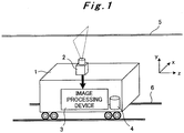
- FIG. 1 to 7 An embodiment of an overhead wire wear measurement device according to the present invention is described using Figs. 1 to 7 .
- a line sensor camera (wear measurement camera) 2 is disposed on the roof of an inspection vehicle (train) 1 as image input means that captures an image of the lower surface of an overhead wire 5, which comes into contact with a pantograph (not shown) .
- An image processing device (image processing unit) 3 and a recording device 4 are disposed inside the inspection vehicle 1.
- the line sensor camera 2 is oriented in such a manner as to capture an image of an area vertically above the inspection vehicle 1 with its scanline direction being the same as the direction of crossties for rails 6, or in other words, orthogonal to the travel direction of the inspection vehicle 1. With such an orientation, a scanline of the line sensor camera 2 crosses the overhead wire 5. Signals representing the image of the lower surface of the overhead wire 5 captured by the line sensor camera 2 are inputted to the image processing device 3.
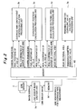
- the image processing device 3 includes a line sensor image creation unit 3a, an overhead wire center point position calculation processing unit 3b, a division point positions calculation processing unit 3c, a wear cross-sectional area calculation processing unit 3d, a remaining-diameter-equivalent value calculation processing unit 3e, and memory M1, M2 as storage means.
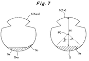
- the image processing device 3 calculates a remaining-diameter-equivalent value H (see Fig. 7(b) ) for an overhead wire with a worn part by performing image processing on the image signals received from the line sensor camera 2.
- the image signals received from the line sensor camera 2 are arranged chronologically by the line sensor image creation unit 3a and stored in the memory M1 as a line sensor image I (see Fig. 4 ) (Step S1).
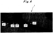
- the pixel positions of points on the line sensor image I shown in Fig. 4 are, for example, set automatically by the system performing the image processing on the line sensor image I or by a user with a GUI, the points on the line sensor image I being the left end p1 of the overhead wire, the left end p2 of a horizontally worn part (an end portion of the horizontally worn part), the division point p3 between the horizontally worn part and an obliquely worn part, the right end p4 of the obliquely worn part (an end portion of the obliquely worn part), and the right end p5 of the overhead wire (which respectively correspond to points P1, P2, P3, P4, and P5 shown in Fig. 6 and are hereinafter referred to simply as division points p1 to p5).
- Camera parameters (focal length, the number of sensor elements, and sensor width) are preset.
- Step S1 the pixel positions of the division points p1 and p5, which are set based on the line sensor image I, are sent to the overhead wire center point position calculation processing unit 3b via the memory M2 along with the camera parameters, and the overhead wire center point position calculation processing unit 3b calculates the real coordinates P0 (x 0 ,y 0 ) of the center point of the overhead wire 5 (Step S2).
- the overhead wire center point position calculation processing unit 3b converts the pixel positions px1 and px5 [pix] of the division points p1 and p5 on the line sensor image I into coordinates u1 and u5 [mm] on the sensor plane shown in Fig. 5 .
- the following computation formulae do not consider lens distortion.
- the pixel positions px1 and px5 [pix] are first converted into sensor-plane coordinates u1' and u5' [mm] by Formula (1) below where the origin is the left end of a sensor plane 2a and ⁇ u is the width of each sensor device.
- the sensor-plane coordinates u1 and u5 [mm] are then obtained by the conversion by Formula (2) below where the origin is the center end of the sensor plane 2a and U is the width of the sensor plane.
- the overhead wire center point position calculation processing unit 3b After finding the sensor-plane coordinates u1 and u5 from the pixel positions px1 and px5 of the division points p1 and p5 on the line sensor image I as described above, the overhead wire center point position calculation processing unit 3b obtains an equation of a straight line L1 passing through the sensor-plane coordinates u1 and the camera center point C and an equation of a straight line L5 passing through the sensor-plane coordinates u5 and the camera center point C as shown in Fig. 5 . Note that the origin of the coordinate system is the camera center point C.
- the straight lines L1 are L5 are each denoted as L
- the sensor-plane coordinates u1 and u5 are each denoted as u
- the gradient a 1 of the straight line L1 and the gradient a 5 of the straight line L5 are each denoted as a
- the gradient ⁇ 1 of the straight line L1 and the gradient ⁇ 5 of the straight line L5 with respect to the x direction are each denoted as ⁇ .
- the overhead wire center point position calculation processing unit 3b finds the real coordinates (x 0 ,y 0 ) of the center point P0 of the overhead wire 5.
- Step S2 the pixel positions of the division points p1 to p5 on the line sensor image I are sent to the division point positions calculation processing unit 3c via the memory M2 along with the camera parameters as shown in Fig. 2 , and the division point positions calculation processing unit 3c finds, as shown in Fig. 3 , the real coordinates P1 (x 1 ,y 1 ), P2 (x 2 ,y 2 ), P3 (x 3 ,y 3 ), P4 (x 4 ,y 4 ), and P5 (x 5 ,y 5 ) of the division points p1, p2, p3, p4, and p5, respectively (Step 3).
- the real coordinates P1 and P5 of the division points p1 and p5 are found.
- the real coordinates P1 and P5 are found using the condition that they are contact points between the overhead wire 5 and the straight lines L1 and L5, respectively.
- the real coordinates P2 and P4 of the division points p2 and p4 are points on a circle of the overhead wire 5 as can be seen in Fig. 6 , and can therefore be found as intersections of the straight lines L2 and L4 and the circle with the radius r centered at the center point P0 (x 0 ,y 0 ) of the overhead wire 5, respectively, shown in Formula (10) below.
- the real coordinates P3 (x 3 ,y 3 ) of the division point p3 are found.
- An equation of the straight line L3 passing through the center point P0 of the overhead wire 5 and P3, i.e., y a 3 x, is found in the same manner as those of the straight lines L2 and L4.
- the y coordinate y 3 of the real coordinates P3 of the division point p3 can be found based on a determination on which of a part between P2 and P3 and a part between P3 and P4 is a horizontally worn part 5a and which of them is an obliquely worn part 5b. As shown in Fig.
- the real coordinates P0 of the center of the overhead wire and the real coordinates P2, P3, and P4 of the division points p2, p3, and p4 are sent to the wear cross-sectional area calculation processing unit 3d via the memory M2 as shown in Fig. 2 , and the wear cross-sectional area calculation processing unit 3d calculates the wear cross-sectional area as shown in Fig. 3 (Step S4).
- a wear cross-sectional area S is found as follows.
- ⁇ 11 arcCos r ⁇ d 1 r
- h 2 rsin ⁇ 12
- the real coordinates P1 and P5 corresponding to p1 and p5 on the line sensor image I are different from the vertexes P6 and P7 of the overhead wire 5 in the x direction, but are rather the contact points between the overhead wire 5 and the straight lines passing through the camera center point C as shown in Fig. 6 .
- the distance d 15 between P1 and P5 is not equal to the diameter 2r of the overhead wire (d 15 #2r).
- the actual wear cross-sectional area can be found if the coordinates of P2, P3, and P4 and r are known.
- Step S5 After the wear cross-sectional area is sent to the remaining-diameter-equivalent value calculation processing unit 3e via the memory M2 as shown in Fig. 2 , the remaining-diameter-equivalent value calculation processing unit 3e calculates a remaining-diameter-equivalent value as shown in Fig. 3 (Step S5).
- the wear angle ⁇ of the horizontally worn overhead wire 5 A which has the same area as the known wear cross-sectional area S AB of the unevenly worn overhead wire 5 AB , is thus found.
- the remaining diameter value of the horizontally worn overhead wire 5 A which has the same area as the known wear cross-sectional area S AB of the unevenly worn overhead wire 5 AB , or in other words, the remaining-diameter-equivalent value H of the unevenly worn overhead wire 5 AB , is thus found.
- the remaining-diameter-equivalent value H thus found is recorded in the recording device 4.
- the overhead wire wear measurement device and the overhead wire wear measurement method according to the present invention are not limited to the ones in the embodiment described above, and can of course be changed variously without departing from the gist of the present invention.
- the division point positions calculation processing unit 3c calculates the real coordinates P1 (x 1 ,y 1 ), P2 (x 2 ,y 2 ), P3 (x 3 ,y 3 ), P4 (x 4 ,y 4 ), and P5 (x 5 ,y 5 ) of the division points p1, p2, p3, p4, and p5 in the above embodiment, the division point positions calculation processing unit 3c may calculate at least the real coordinates P2 (x 2 ,y 2 ), P3 (x 3 ,y 3 ), and P4 (x 4 ,y 4 ) of the division points p2, p3, and p4.
- the worn surface of the overhead wire 5 has one horizontally worn part 5a and one obliquely worn part 5b in the embodiment described above, the worn surface of the overhead wire 5 may have a different wear shape.
- the tensile strength of the overhead wire 5 can be accurately found even if the overhead wire 5 is the unevenly worn overhead wire 5 AB having the horizontally worn part 5a and the obliquely worn part 5b, because the remaining-diameter-equivalent value H which takes the horizontally worn part 5a and the obliquely worn part 5b into account can be calculated for the unevenly worn overhead wire 5 AB based on a remaining cross-sectional area found using the wear cross-sectional area S AB .
- the remaining-diameter-equivalent value H can be handled in the same way as the remaining diameter value for the regular horizontally worn overhead wire 5 A , the management of the unevenly worn overhead wire 5 AB and the regular horizontally worn overhead wire 5 A can be advantageously unified.
- the idea of finding the remaining-diameter-equivalent value H from a cross-sectional area is flexibly applicable not only to an overhead wire with uneven wear, but also to an overhead wire with a different wear shape.
- the present invention is suitably applicable to an overhead wire wear measurement device and an overhead wire wear measurement method for finding the remaining diameter of an overhead wire by capturing an image of the lower surface of the overhead wire, which comes into contact with a pantograph, with a wear measurement camera disposed on the roof of a train and by performing image processing on the captured image of the lower surface of the overhead wire.
Landscapes
- Engineering & Computer Science (AREA)
- Manufacturing & Machinery (AREA)
- Mechanical Engineering (AREA)
- Physics & Mathematics (AREA)
- General Physics & Mathematics (AREA)
- Length Measuring Devices By Optical Means (AREA)
Abstract
Description
- The present invention relates to a field of overhead wire inspection that measures wear of an overhead wire by capturing an image of the width of the lower surface of the overhead wire from the top of a train roof and by performing image processing on the image. The present invention particularly relates to an overhead wire wear measurement device and an overhead wire wear measurement method that determine a remaining-diameter-equivalent value for an overhead wire the pantograph-sliding surface of which is partly oblique (an unevenly worn overhead wire), the remaining-diameter-equivalent value serving as an index to know whether the overhead wire has reached the end of its life.
-
Fig. 8 shows a schematic, cross-sectional view of an overhead wire. Due to a contact with a pantograph (not shown), anunworn overhead wire 5 shown inFig. 8(a) wears in such a manner that its lower surface becomes parallel to the horizontal plane as shown inFig. 8 (b) or becomes oblique to the horizontal plane as shown inFig. 8 (c) . Hereinafter, a part of an overhead wire that has worn away to be parallel to the horizontal plane is referred to as a horizontallyworn part 5a, and a part of an overhead wire that has worn away to be oblique to the horizontal plane is referred to as an obliquelyworn part 5b. - At areas of the
overhead wire 5 where an overlap is present or where a crossover wire is also present, theoverhead wire 5 may also come to have a wear part in a wear state called uneven wear formed by the horizontallyworn part 5a and the obliquelyworn part 5b, as shown inFig. 8(d) . - Regarding wear of the
overhead wire 5,Patent Document 1 below describes an overhead wire measurement method for measuring the amount of wear of theoverhead wire 5 having the horizontallyworn part 5a like the one shown inFig. 8(b) . In addition,Patent Document 2 below describes an overhead wire measurement method for measuring the amount of wear of theoverhead wire 5 having the obliquelyworn part 5b like the one shown inFig. 8 (c) . -
Patent Document 3 discloses use of laser light to measure uneven wear of theoverhead wire 5 like the one shown inFig. 8(d) .Patent Document 3 converts the horizontallyworn part 5a and the obliquelyworn part 5b into binary representations based on the difference in the intensity of reflected laser light, and as shown inFig. 9 , calculates a remaining diameter HA of the horizontallyworn part 5a and a remaining diameter HB of the obliquelyworn part 5b using the widths of the horizontallyworn part 5a and the obliquelyworn part 5b and a prepared remaining diameter table. -
- Patent Document 1: Japanese Patent No.
4635657 - Patent Document 2: Japanese Patent No.
5534058 - Patent Document 3: Japanese Patent No.
5380000 - Non-Patent Document 1: "Overview of Electricity for Railway Engineers,
- As described in
Non-Patent Document 1, theoverhead wire 5 may break when decreased in tensile strength. The tensile strength of theoverhead wire 5 correlates with the area of a remaining cross section of theoverhead wire 5, and therefore a remaining diameter calculated by measurement of an overhead wire should be set such that the remaining diameter correlates with the remaining cross-sectional area. To be more specific, it is contemplated that an appropriate index of the wear state of an unevenly worn overhead wire having the horizontallyworn part 5a and the obliquelyworn part 5b should be represented not by the two remaining diameters, namely the remaining diameters of the horizontallyworn part 5a and the obliquelyworn part 5b, but by a single value based on the cross-sectional area (such a value is hereinafter referred to as a remaining-diameter-equivalent value). - The conventional overhead wire measurement methods described above can obtain the remaining diameter values of the horizontally
worn part 5a and the obliquelyworn part 5b, but cannot obtain a single remaining-diameter-equivalent value which is based on the remaining cross-sectional area and takes the horizontallyworn part 5a and the obliquelyworn part 5b into account, particularly for theoverhead wire 5 in an unevenly worn state. It has therefore been difficult to find an accurate tensile strength of theoverhead wire 5. - In view of such circumstances, the present invention aims to provide an overhead wire wear measurement device and an overhead wire wear measurement method capable of calculating a single remaining-diameter-equivalent value which is based on the remaining cross-sectional area and takes a horizontally worn part and an obliquely worn part into account.
- To solve the above problem, an overhead wire wear measurement method according to a first aspect of the invention is an overhead wire wear measurement method for finding a remaining diameter of an overhead wire by capturing an image of a lower surface of the overhead wire, which comes into contact with a pantograph, with a wear measurement camera disposed on a roof of a train and by performing image processing on the captured image of the lower surface of the overhead wire, characterized in that
a remaining diameter of a horizontally worn overhead wire having only a horizontally worn part is calculated as a remaining-diameter-equivalent value for an unevenly worn overhead wire having the horizontally worn part and an obliquely worn part, the horizontally worn overhead wire having the same cross-sectional area as the unevenly worn overhead wire. - An overhead wire wear measurement method according to a second aspect of the invention is characterized in that
the method comprises the steps of: - calculating real coordinates of a center point of the overhead wire from the image of the lower surface of the overhead wire;
- calculating real coordinates of an end portion of the horizontally worn part, real coordinates of a division point between the horizontally worn part and the obliquely worn part, and real coordinates of an end portion of the obliquely worn part from the image of the lower surface of the overhead wire;
- calculating a cross-sectional area of the unevenly worn overhead wire based on the real coordinates of the center point of the overhead wire, the real coordinates of the end portion of the horizontally worn part, the real coordinates of the division point between the horizontally worn part and the obliquely worn part, and the real coordinates of the end portion of the obliquely worn part; and
- calculating the remaining-diameter-equivalent value based on the cross-sectional area of the unevenly worn overhead wire.
- An overhead wire wear measurement device according to a third aspect of the invention is an overhead wire wear measurement device comprising an image processing unit that finds a remaining diameter of an overhead wire by causing a wear measurement camera disposed on a roof of a train to capture an image of a lower surface of the overhead wire, which comes into contact with a pantograph and by performing image processing on the captured image of the lower surface of the overhead wire, characterized in that
the image processing unit includes a remaining-diameter-equivalent value calculation processing unit that calculates a remaining diameter of a horizontally worn overhead wire having only a horizontally worn part, as a remaining-diameter-equivalent value for an unevenly worn overhead wire having the horizontally worn part and an obliquely worn part, the horizontally worn overhead wire having the same cross-sectional area as the unevenly worn overhead wire. - An overhead wire wear measurement device according to a fourth aspect of the invention is characterized in that
the image processing unit includes - an overhead wire center point position calculation processing unit that calculates real coordinates of a center point of the overhead wire from the image of the lower surface of the overhead wire;
- a division point positions calculation processing unit that calculates at least real coordinates of an end portion of the horizontally worn part, real coordinates of a division point between the horizontally worn part and the obliquely worn part, and real coordinates of an end portion of the obliquely worn part from the image of the lower surface of the overhead wire; and
- a wear cross-sectional area calculation processing unit that calculates a cross-sectional area of the unevenly worn overhead wire based on the real coordinates of the center point of the overhead wire calculated by the overhead wire center point position calculation processing unit and on the real coordinates of the end portion of the horizontally worn part, the real coordinates of the division point between the horizontally worn part and the obliquely worn part, and the real coordinates of the end portion of the obliquely worn part calculated by the division point positions calculation processing unit, and
- An overhead wire wear measurement device and an overhead wire wear measurement method according to the present invention can find an accurate tensile strength of even an unevenly worn overhead wire having a worn part formed by a horizontally worn part and an obliquely worn part by calculating a remaining-diameter-equivalent value taking a remaining cross-sectional area into account.
-
- [
Fig. 1] Fig. 1 is a diagram illustrating an overhead wire wear measurement device according to an embodiment of the present invention. - [
Fig. 2] Fig. 2 is a diagram of the configuration of the overhead wire wear measurement device according to the embodiment of the present invention. - [
Fig. 3] Fig. 3 is a flowchart of processing performed by an image processing unit of the overhead wire wear measurement device according to the embodiment of the present invention. - [
Fig. 4] Fig. 4 is a diagram illustrating an example of a line sensor image. - [
Fig. 5] Fig. 5 is a diagram illustrating the relations among an overhead wire, a camera center point, and a sensor plane. - [
Fig. 6] Fig. 6 is a diagram illustrating a method for calculating the cross-sectional area of an overhead wire. - [
Fig. 7] Fig. 7 is a diagram illustrating a method for calculating a remaining-diameter-equivalent value. - [
Fig. 8] Fig. 8 includes schematic diagrams showing cross-sections of an overhead wire,Fig. 8 (a) showing an unworn overhead wire,Fig. 8(b) showing an overhead wire with a horizontally worn part,Fig. 8(c) showing an overhead wire with an obliquely worn part, andFig. 8 (d) showing an overhead wire with a horizontally worn part and an obliquely worn part. - [
Fig. 9] Fig. 9 is a diagram illustrating an example conventional method for calculating the remaining diameters of an unevenly worn overhead wire. - An overhead wire wear measurement device according to the present invention is described in detail below with reference to the drawings.
- An embodiment of an overhead wire wear measurement device according to the present invention is described using
Figs. 1 to 7 . - In the present embodiment, as shown in
Fig. 1 , a line sensor camera (wear measurement camera) 2 is disposed on the roof of an inspection vehicle (train) 1 as image input means that captures an image of the lower surface of anoverhead wire 5, which comes into contact with a pantograph (not shown) . An image processing device (image processing unit) 3 and arecording device 4 are disposed inside theinspection vehicle 1. - The
line sensor camera 2 is oriented in such a manner as to capture an image of an area vertically above theinspection vehicle 1 with its scanline direction being the same as the direction of crossties forrails 6, or in other words, orthogonal to the travel direction of theinspection vehicle 1. With such an orientation, a scanline of theline sensor camera 2 crosses theoverhead wire 5. Signals representing the image of the lower surface of theoverhead wire 5 captured by theline sensor camera 2 are inputted to theimage processing device 3. - As shown in
Fig. 2 , theimage processing device 3 includes a line sensor image creation unit 3a, an overhead wire center point positioncalculation processing unit 3b, a division point positionscalculation processing unit 3c, a wear cross-sectional areacalculation processing unit 3d, a remaining-diameter-equivalent valuecalculation processing unit 3e, and memory M1, M2 as storage means. - Following the flowchart shown in
Fig 3 , theimage processing device 3 calculates a remaining-diameter-equivalent value H (seeFig. 7(b) ) for an overhead wire with a worn part by performing image processing on the image signals received from theline sensor camera 2. - To be more specific, in the
image processing device 3, the image signals received from theline sensor camera 2 are arranged chronologically by the line sensor image creation unit 3a and stored in the memory M1 as a line sensor image I (seeFig. 4 ) (Step S1). - In the present embodiment, the pixel positions of points on the line sensor image I shown in
Fig. 4 are, for example, set automatically by the system performing the image processing on the line sensor image I or by a user with a GUI, the points on the line sensor image I being the left end p1 of the overhead wire, the left end p2 of a horizontally worn part (an end portion of the horizontally worn part), the division point p3 between the horizontally worn part and an obliquely worn part, the right end p4 of the obliquely worn part (an end portion of the obliquely worn part), and the right end p5 of the overhead wire (which respectively correspond to points P1, P2, P3, P4, and P5 shown inFig. 6 and are hereinafter referred to simply as division points p1 to p5). Camera parameters (focal length, the number of sensor elements, and sensor width) are preset. - After Step S1, the pixel positions of the division points p1 and p5, which are set based on the line sensor image I, are sent to the overhead wire center point position
calculation processing unit 3b via the memory M2 along with the camera parameters, and the overhead wire center point positioncalculation processing unit 3b calculates the real coordinates P0 (x0,y0) of the center point of the overhead wire 5 (Step S2). - More specifically, first, the overhead wire center point position
calculation processing unit 3b converts the pixel positions px1 and px5 [pix] of the division points p1 and p5 on the line sensor image I into coordinates u1 and u5 [mm] on the sensor plane shown inFig. 5 . For simple illustration, it is assumed that the following computation formulae do not consider lens distortion. - The pixel positions px1 and px5 [pix] are first converted into sensor-plane coordinates u1' and u5' [mm] by Formula (1) below where the origin is the left end of a
sensor plane 2a and Δu is the width of each sensor device. The sensor-plane coordinates u1 and u5 [mm] are then obtained by the conversion by Formula (2) below where the origin is the center end of thesensor plane 2a and U is the width of the sensor plane. Note that in Formulae (1) and (2) the pixel positions px1 and px5 are each denoted as px, the sensor-plane coordinates u1' and u5' are each denoted as u', and the sensor-plane coordinates u1 and u5 are each denoted as u.

- The results are more accurate if the conversions are made considering lens distortion.
- After finding the sensor-plane coordinates u1 and u5 from the pixel positions px1 and px5 of the division points p1 and p5 on the line sensor image I as described above, the overhead wire center point position
calculation processing unit 3b obtains an equation of a straight line L1 passing through the sensor-plane coordinates u1 and the camera center point C and an equation of a straight line L5 passing through the sensor-plane coordinates u5 and the camera center point C as shown inFig. 5 . Note that the origin of the coordinate system is the camera center point C. - The equations of the straight lines L1 and L5 are given by Formula (3) below using a focal length f.


- Using the equations of the straight lines L1 and L5, the gradients a1 and a5 of the straight lines L1 and L5, and the gradients θ1 and θ5 of the straight lines L1 and L5 with respect to the x direction found above, the overhead wire center point position
calculation processing unit 3b finds the real coordinates (x0,y0) of the center point P0 of theoverhead wire 5. - Specifically, as shown in
Fig. 5 , an equation of a straight line L0 passing through the center point P0 of theoverhead wire 5 and the camera center point C is found by Formula (5) below:
- Since the distance from the center point P0 (x0,y0) of the
overhead wire 5 on the straight line L0 to the straight line L1 is equal to the radius r [mm] of the overhead wire, the x coordinate x0 of the center point P0 of theoverhead wire 5 is found by Formula (6) below. Further, y0 is obtained by y0=a0x0. Formula (6) is derived using a "distance d from a point to a line formula" of Formula (7) below.
[Expression 1]

- The real coordinates P0 (x0,y0) of the center point of the
overhead wire 5 is thus found. - After Step S2, the pixel positions of the division points p1 to p5 on the line sensor image I are sent to the division point positions
calculation processing unit 3c via the memory M2 along with the camera parameters as shown inFig. 2 , and the division point positionscalculation processing unit 3c finds, as shown inFig. 3 , the real coordinates P1 (x1,y1), P2 (x2,y2), P3 (x3,y3), P4 (x4,y4), and P5 (x5,y5) of the division points p1, p2, p3, p4, and p5, respectively (Step 3). - First, the real coordinates P1 and P5 of the division points p1 and p5 are found. The real coordinates P1 and P5 are found using the condition that they are contact points between the
overhead wire 5 and the straight lines L1 and L5, respectively. Specifically, P1 is the intersection of the straight line L1 (y=a1x) and a perpendicular y=(-1/a1)x+(1/a1)x0+y0) to the straight line L1 passing through the center point P0 (x0,y0) of theoverhead wire 5, and P5 is the intersection of the straight line L5 (y=a5x) and a perpendicular y=(-1/a5)x+(1/a5)x0+y0 to the straight line L5 passing through the center point P0 (x0,y0) of theoverhead wire 5. The x coordinate and the y coordinate of each of the real coordinates P1 and P5 are given by Formulae (8) and (9), respectively.
[Expression 2]

- To calculate the real coordinates P2, P3, and P4 of the division points p2, p3, and p4, the real coordinates P2 and P4 of the division points p2 and p4 are found first. Equations of the straight lines L2 (y=a2x) and L4 (y=a4x) are found in the same manner as those of L1 and L5. The real coordinates P2 and P4 of the division points p2 and p4 are points on a circle of the
overhead wire 5 as can be seen inFig. 6 , and can therefore be found as intersections of the straight lines L2 and L4 and the circle with the radius r centered at the center point P0 (x0,y0) of theoverhead wire 5, respectively, shown in Formula (10) below. Note that in Formula (10), the x coordinates x2 and x4 of the real coordinates P2 and P4 are each denoted as x, and the gradients a2 and a4 of the straight lines L2 and L4 are each denoted as a.
[Expression 3]
- The y coordinates y2 and y4 of the real coordinates P2 and P4 are given by y2=a2x2 and y4=a4x4.
- The real coordinates P2 (x2,y2) and the real coordinates P4 (x4,y4) are thus found.
- Next, the real coordinates P3 (x3,y3) of the division point p3 are found. An equation of the straight line L3 passing through the center point P0 of the
overhead wire 5 and P3, i.e., y=a3x, is found in the same manner as those of the straight lines L2 and L4. The y coordinate y3 of the real coordinates P3 of the division point p3 can be found based on a determination on which of a part between P2 and P3 and a part between P3 and P4 is a horizontallyworn part 5a and which of them is an obliquelyworn part 5b. As shown inFig. 6 , when theoverhead wire 5 has the horizontallyworn part 5a and the obliquelyworn part 5b, which is worn off more than the horizontallyworn part 5a, the y coordinate y3 of the real coordinates P3 can be determined based on the y coordinates y2 and y4 of P2 and P4. Specifically, the smaller y coordinate of the real coordinates P2 and P4 is the same as the y coordinate y3 of P3. This can be given by Formula (11) below as a conditional equation.
[Expression 4]
- Then, x3 can be obtained using x3=y3/a3.
- The real coordinates P3 (x3,y3) of the division point p3 is thus found.
- Next, the real coordinates P0 of the center of the overhead wire and the real coordinates P2, P3, and P4 of the division points p2, p3, and p4 are sent to the wear cross-sectional area
calculation processing unit 3d via the memory M2 as shown inFig. 2 , and the wear cross-sectional areacalculation processing unit 3d calculates the wear cross-sectional area as shown inFig. 3 (Step S4). - Processing to calculate the wear cross-sectional area is described specifically below.
- First, a description is given of the wear cross-sectional area calculation processing in an ideal situation. The following case is considered as an example: with P6 and P7 being the x-direction vertexes of the
overhead wire 5 with the radius r [mm] as shown inFig. 6 , the distance d1, d2, d3, and d4 [mm], measured in the x direction, of a part between P6 and P2, a part between P2 to P3, a part between P3 and P4, and a part between P4 and P7 are known (d1+d2+d3+d4=2r). - In this case, a wear cross-sectional area S is found as follows.
- Specifically, with the parameters d1, d2, d3, and d4 given, the wear cross-sectional area S is found by Formula (12) below using the areas S1 and S2 of sectors P6P0P2 and P4P0P7 and the areas of S3 and S4 of triangles P0P2P4 and P2P3P4.
[Expression 5]
- When θ11 (=∠P2P0P6) and θ12 (=∠P4P0P7) are given by Formula (13) below and h1, h2, and h4 are given by Formula (14) below, the wear cross-sectional area S is expressed as Formula (15) below.
[Expression 6]


- In the ideal situation described above, the vertexes P6 and P7 are the ends of the overhead wire, and the distance d67 between P6 and P7 is the diameter 2r of the overhead wire (d67=2r). However, when the
overhead wire 5 is captured by theline sensor camera 2, the real coordinates P1 and P5 corresponding to p1 and p5 on the line sensor image I are different from the vertexes P6 and P7 of theoverhead wire 5 in the x direction, but are rather the contact points between theoverhead wire 5 and the straight lines passing through the camera center point C as shown inFig. 6 . For this reason, the distance d15 between P1 and P5 is not equal to the diameter 2r of the overhead wire (d15#2r). - What also needs to be considered is that, as shown in
Fig. 5 , the positions of P1 and P5 relative to the center P0 of the overhead wire vary depending on the deviation positions of theoverhead wire 5 from theline sensor camera 2. The following method obtains a remaining-diameter-equivalent value for the overhead wire with the above points taken into account. - Specifically, the actual wear cross-sectional area can be found if the coordinates of P2, P3, and P4 and r are known. First, if the length d24 between P2 and P4 is found, the area S3 of the triangle P0P2P4 is given by Formula (16) because the lengths of the sides of the triangle (d24, r, r) are known.
[Expression 7]
- In the above formula, a=d24, and b=c=r.
- The area S4 of the triangle P2P3P4 can be found in the same manner as the area S3 by a formula for calculating the area of a triangle using the known lengths of its sides, namely the length d23 (=d2) between P2 and P3, the length d34 between P3 and P4, and the length d24 between P2 and P4.
- Next, ∠P2P0P4 (=θ13) is found. Specifically, using the basic formula for finding the area of a triangle, i.e., area = (base × height) /2, the height h of the triangle P0P2P4 is found with the base being P2P4. Then, using the properties of an isosceles triangle, the angle θ13 is found by Formula (17) below.
[Expression 8]
- The area of the sector P2P0P4 is found using the angle θ13, and the wear cross-sectional area S is given by S= (the area of the sector P2POP4) - (S3+S4).
- Next, after the wear cross-sectional area is sent to the remaining-diameter-equivalent value
calculation processing unit 3e via the memory M2 as shown inFig. 2 , the remaining-diameter-equivalent valuecalculation processing unit 3e calculates a remaining-diameter-equivalent value as shown inFig. 3 (Step S5). - A description is given of a method for finding a remaining-diameter-equivalent value H for a part of the
overhead wire 5 having the horizontallyworn part 5a and the obliquelyworn part 5b (the part of theoverhead wire 5 having the horizontallyworn part 5a and the obliquelyworn part 5b is hereinafter referred to as an unevenly wornoverhead wire 5AB.) First, a formula to find the wear cross-sectional area S of theoverhead wire 5 having only the horizontallyworn part 5a (hereinafter referred to as a horizontally worn overhead wire 5A) is given by Formula (18) below using the radius r of the horizontally wornoverhead wire 5A and a wear angle α shown inFig. 7(b) .
[Expression 9]
- In Formula (19) below, if the wear cross-sectional area SAB of the unevenly worn
overhead wire 5AB is known, the wear angle α can be calculated by Formula (20) by substitution of S in Formula (19) below using Newton's Method.
[Expression 10]

- As shown in
Fig. 7(b) , the wear angle α of the horizontally wornoverhead wire 5A, which has the same area as the known wear cross-sectional area SAB of the unevenly wornoverhead wire 5AB, is thus found. - Using α thus found, the remaining-diameter-equivalent value H is found by Formula (21) below.
[Expression 11]
- The remaining diameter value of the horizontally worn
overhead wire 5A, which has the same area as the known wear cross-sectional area SAB of the unevenly wornoverhead wire 5AB, or in other words, the remaining-diameter-equivalent value H of the unevenly wornoverhead wire 5AB, is thus found. - The remaining-diameter-equivalent value H thus found is recorded in the
recording device 4. - The overhead wire wear measurement device and the overhead wire wear measurement method according to the present invention are not limited to the ones in the embodiment described above, and can of course be changed variously without departing from the gist of the present invention.
- For example, although the division point positions
calculation processing unit 3c calculates the real coordinates P1 (x1,y1), P2 (x2,y2), P3 (x3,y3), P4 (x4,y4), and P5 (x5,y5) of the division points p1, p2, p3, p4, and p5 in the above embodiment, the division point positionscalculation processing unit 3c may calculate at least the real coordinates P2 (x2,y2), P3 (x3,y3), and P4 (x4,y4) of the division points p2, p3, and p4. - Although the worn surface of the
overhead wire 5 has one horizontallyworn part 5a and one obliquelyworn part 5b in the embodiment described above, the worn surface of theoverhead wire 5 may have a different wear shape. - According to the overhead wire wear measurement device and the overhead wire wear measurement method of the embodiment described above, the tensile strength of the
overhead wire 5 can be accurately found even if theoverhead wire 5 is the unevenly wornoverhead wire 5AB having the horizontallyworn part 5a and the obliquelyworn part 5b, because the remaining-diameter-equivalent value H which takes the horizontallyworn part 5a and the obliquelyworn part 5b into account can be calculated for the unevenly wornoverhead wire 5AB based on a remaining cross-sectional area found using the wear cross-sectional area SAB. - Since the remaining-diameter-equivalent value H can be handled in the same way as the remaining diameter value for the regular horizontally worn
overhead wire 5A, the management of the unevenly wornoverhead wire 5AB and the regular horizontally wornoverhead wire 5A can be advantageously unified. The idea of finding the remaining-diameter-equivalent value H from a cross-sectional area is flexibly applicable not only to an overhead wire with uneven wear, but also to an overhead wire with a different wear shape. - The present invention is suitably applicable to an overhead wire wear measurement device and an overhead wire wear measurement method for finding the remaining diameter of an overhead wire by capturing an image of the lower surface of the overhead wire, which comes into contact with a pantograph, with a wear measurement camera disposed on the roof of a train and by performing image processing on the captured image of the lower surface of the overhead wire.
-
- 1 vehicle
- 2 line sensor camera
- 3 image processing device
- 3a line sensor image creation unit
- 3b overhead wire center point position calculation processing unit
- 3c division point positions calculation processing unit
- 3d wear cross-sectional area calculation processing unit
- 3e remaining-diameter-equivalent value calculation processing unit
- 4 recording device
- 5 overhead wire
- 5A horizontally worn overhead wire
- 5AB unevenly worn overhead wire
- 5a horizontally worn part
- 5b obliquely worn part
- 6 rails
- M1,M2 memory
Claims (4)
- An overhead wire wear measurement method for finding a remaining diameter of an overhead wire by capturing an image of a lower surface of the overhead wire, which comes into contact with a pantograph, with a wear measurement camera disposed on a roof of a train and by performing image processing on the captured image of the lower surface of the overhead wire, characterized in that
a remaining diameter of a horizontally worn overhead wire having only a horizontally worn part is calculated as a remaining-diameter-equivalent value for an unevenly worn overhead wire having a horizontally worn part and an obliquely worn part, the horizontally worn overhead wire having the same cross-sectional area as the unevenly worn overhead wire. - The overhead wire wear measurement method according to claim 1, characterized in that
the method comprises the steps of:calculating real coordinates of a center point of the overhead wire from the image of the lower surface of the overhead wire;calculating real coordinates of an end portion of the horizontally worn part, real coordinates of a division point between the horizontally worn part and the obliquely worn part, and real coordinates of an end portion of the obliquely worn part from the image of the lower surface of the overhead wire;calculating a cross-sectional area of the unevenly worn overhead wire based on the real coordinates of the center point of the overhead wire, the real coordinates of the end portion of the horizontally worn part, the real coordinates of the division point between the horizontally worn part and the obliquely worn part, and the real coordinates of the end portion of the obliquely worn part; andcalculating the remaining-diameter-equivalent value based on the cross-sectional area of the unevenly worn overhead wire. - An overhead wire wear measurement device comprising an image processing unit that finds a remaining diameter of an overhead wire by causing a wear measurement camera disposed on a roof of a train to capture an image of a lower surface of the overhead wire, which comes into contact with a pantograph and by performing image processing on the captured image of the lower surface of the overhead wire, characterized in that
the image processing unit includes a remaining-diameter-equivalent value calculation processing unit that calculates a remaining diameter of a horizontally worn overhead wire having only a horizontally worn part, as a remaining-diameter-equivalent value for an unevenly worn overhead wire having a horizontally worn part and an obliquely worn part, the horizontally worn overhead wire having the same cross-sectional area as the unevenly worn overhead wire. - The overhead wire wear measurement device according to claim 3, characterized in that
the image processing unit includesan overhead wire center point position calculation processing unit that calculates real coordinates of a center point of the overhead wire from the image of the lower surface of the overhead wire;a division point positions calculation processing unit that calculates at least real coordinates of an end portion of the horizontally worn part, real coordinates of a division point between the horizontally worn part and the obliquely worn part, and real coordinates of an end portion of the obliquely worn part from the image of the lower surface of the overhead wire; anda wear cross-sectional area calculation processing unit that calculates a cross-sectional area of the unevenly worn overhead wire based on the real coordinates of the center point of the overhead wire calculated by the overhead wire center point position calculation processing unit and on the real coordinates of the end portion of the horizontally worn part, the real coordinates of the division point between the horizontally worn part and the obliquely worn part, and the real coordinates of the end portion of the obliquely worn part calculated by the division point positions calculation processing unit, andthe wear cross-sectional area calculation processing unit calculates the remaining-diameter-equivalent value based on the cross-sectional area of the unevenly worn overhead wire calculated by the wear cross-sectional area calculation processing unit.
Applications Claiming Priority (2)
| Application Number | Priority Date | Filing Date | Title |
|---|---|---|---|
| JP2015016220A JP6450971B2 (en) | 2015-01-30 | 2015-01-30 | Trolley wire wear measuring device and trolley wire wear measuring method |
| PCT/JP2016/052232 WO2016121779A1 (en) | 2015-01-30 | 2016-01-27 | Overhead wire wear measurement device and overhead wire wear measurement method |
Publications (3)
| Publication Number | Publication Date |
|---|---|
| EP3252428A1 true EP3252428A1 (en) | 2017-12-06 |
| EP3252428A4 EP3252428A4 (en) | 2018-07-04 |
| EP3252428B1 EP3252428B1 (en) | 2019-09-18 |
Family
ID=56543390
Family Applications (1)
| Application Number | Title | Priority Date | Filing Date |
|---|---|---|---|
| EP16743382.0A Active EP3252428B1 (en) | 2015-01-30 | 2016-01-27 | Overhead wire wear measurement device and overhead wire wear measurement method |
Country Status (7)
| Country | Link |
|---|---|
| EP (1) | EP3252428B1 (en) |
| JP (1) | JP6450971B2 (en) |
| CN (1) | CN107209005B (en) |
| MY (1) | MY194956A (en) |
| SG (1) | SG11201705970VA (en) |
| TW (1) | TWI593939B (en) |
| WO (1) | WO2016121779A1 (en) |
Cited By (2)
| Publication number | Priority date | Publication date | Assignee | Title |
|---|---|---|---|---|
| EP3945281A1 (en) * | 2020-07-28 | 2022-02-02 | VolkerWessels Intellectuele Eigendom B.V. | Optical measurement system for an overhead line |
| CN116147525A (en) * | 2023-04-17 | 2023-05-23 | 南京理工大学 | A pantograph profile detection method and system based on improved ICP algorithm |
Families Citing this family (8)
| Publication number | Priority date | Publication date | Assignee | Title |
|---|---|---|---|---|
| JP6575087B2 (en) * | 2015-03-19 | 2019-09-18 | 株式会社明電舎 | Trolley wire wear measuring device |
| JP6855405B2 (en) * | 2018-03-20 | 2021-04-07 | 公益財団法人鉄道総合技術研究所 | Tram wire measuring method and trolley wire measuring device |
| CN109130955B (en) * | 2018-09-29 | 2021-07-20 | 武汉理工大学 | A high-speed railway suspension chord pre-arrangement method for compensating for the influence of contact wire wear |
| JP7159790B2 (en) * | 2018-10-29 | 2022-10-25 | 株式会社明電舎 | Catenary wear detector |
| JP6635183B1 (en) * | 2018-12-19 | 2020-01-22 | 株式会社明電舎 | Wear measuring device and wear measuring method |
| JP7348801B2 (en) * | 2019-10-08 | 2023-09-21 | 株式会社プロテリアル | contact wire |
| CN112325781B (en) * | 2020-10-16 | 2022-05-17 | 易思维(杭州)科技有限公司 | Rail transit contact line wear detection device and method |
| CN117104087A (en) * | 2023-08-04 | 2023-11-24 | 中铁十六局集团电气化工程有限公司 | A method and device for precise preconfiguration of contact network wrist arms |
Family Cites Families (14)
| Publication number | Priority date | Publication date | Assignee | Title |
|---|---|---|---|---|
| JPS535655A (en) * | 1976-07-05 | 1978-01-19 | Omron Tateisi Electronics Co | Trolley line wear measurement |
| JPS5380000A (en) * | 1976-12-24 | 1978-07-14 | Mitsubishi Chem Ind Ltd | Process for curing epoxy compound |
| JPS5946595B2 (en) * | 1978-09-01 | 1984-11-13 | 日本原子力研究所 | Method for immobilizing biologically active substances on microparticle carriers |
| IT1285466B1 (en) * | 1996-02-23 | 1998-06-08 | Riccardo Dallara | ELECTRICAL LINES CONTROL EQUIPMENT |
| DE19634060C1 (en) * | 1996-08-23 | 1998-01-22 | Fraunhofer Ges Forschung | Over-head wire supervision arrangement for electrically operated vehicle |
| JP4635657B2 (en) * | 2005-03-11 | 2011-02-23 | 株式会社明電舎 | Trolley wire wear measuring device by image processing |
| JP2006250776A (en) * | 2005-03-11 | 2006-09-21 | Meidensha Corp | Abrasion state measuring device of trolley line by image processing |
| JP5380000B2 (en) * | 2008-05-13 | 2013-12-25 | 西日本旅客鉄道株式会社 | Trolley wire wear amount measuring method and measuring system |
| JP5223472B2 (en) * | 2008-06-06 | 2013-06-26 | 株式会社明電舎 | Wear measuring apparatus and wear measuring method |
| JP5423567B2 (en) * | 2010-04-30 | 2014-02-19 | 株式会社明電舎 | Vehicle position measuring device for electric railway maintenance |
| JP5534058B1 (en) * | 2013-02-19 | 2014-06-25 | 株式会社明電舎 | Wear measuring apparatus and method |
| DE102013008600B3 (en) * | 2013-05-22 | 2014-08-28 | Db Netz Ag | Method for optical contact wire strength measurement of a catenary of rail traffic |
| JP6322869B2 (en) * | 2014-03-25 | 2018-05-16 | 公益財団法人鉄道総合技術研究所 | Trolley wire wear amount calculation method and trolley wire wear amount calculation device |
| JP6347069B2 (en) * | 2014-05-30 | 2018-06-27 | 株式会社明電舎 | Apparatus and method for measuring trolley wire wear by image processing |
-
2015
- 2015-01-30 JP JP2015016220A patent/JP6450971B2/en active Active
-
2016
- 2016-01-27 CN CN201680007636.6A patent/CN107209005B/en not_active Expired - Fee Related
- 2016-01-27 SG SG11201705970VA patent/SG11201705970VA/en unknown
- 2016-01-27 WO PCT/JP2016/052232 patent/WO2016121779A1/en not_active Ceased
- 2016-01-27 EP EP16743382.0A patent/EP3252428B1/en active Active
- 2016-01-27 MY MYPI2017702773A patent/MY194956A/en unknown
- 2016-01-29 TW TW105102949A patent/TWI593939B/en active
Cited By (3)
| Publication number | Priority date | Publication date | Assignee | Title |
|---|---|---|---|---|
| EP3945281A1 (en) * | 2020-07-28 | 2022-02-02 | VolkerWessels Intellectuele Eigendom B.V. | Optical measurement system for an overhead line |
| NL2026149B1 (en) * | 2020-07-28 | 2022-03-29 | Volkerwessels Intellectuele Eigendom B V | Optical measurement system for an overheadline |
| CN116147525A (en) * | 2023-04-17 | 2023-05-23 | 南京理工大学 | A pantograph profile detection method and system based on improved ICP algorithm |
Also Published As
| Publication number | Publication date |
|---|---|
| TWI593939B (en) | 2017-08-01 |
| TW201632829A (en) | 2016-09-16 |
| EP3252428B1 (en) | 2019-09-18 |
| CN107209005A (en) | 2017-09-26 |
| CN107209005B (en) | 2019-11-08 |
| EP3252428A4 (en) | 2018-07-04 |
| SG11201705970VA (en) | 2017-08-30 |
| JP6450971B2 (en) | 2019-01-16 |
| WO2016121779A1 (en) | 2016-08-04 |
| MY194956A (en) | 2022-12-28 |
| JP2016142540A (en) | 2016-08-08 |
Similar Documents
| Publication | Publication Date | Title |
|---|---|---|
| EP3252428B1 (en) | Overhead wire wear measurement device and overhead wire wear measurement method | |
| JP4635657B2 (en) | Trolley wire wear measuring device by image processing | |
| EP2960620B1 (en) | Wear measuring device and method for same | |
| KR101280243B1 (en) | Measuring system for height and stagger and wear of catenary using machine vision | |
| CN105393080B (en) | Overhead line measurement device and overhead line assay method | |
| JP6424362B2 (en) | Filament measurement apparatus and method thereof | |
| JP5494286B2 (en) | Overhead position measuring device | |
| EP2966400B1 (en) | Overhead line position measuring device and method | |
| CN102292236B (en) | Pantograph height measuring device | |
| JP5549488B2 (en) | Trolley wire inspection device | |
| JP5952759B2 (en) | Overhead wire position measuring apparatus and method | |
| JP6311757B2 (en) | Insulator detecting device and insulator detecting method | |
| JP6347069B2 (en) | Apparatus and method for measuring trolley wire wear by image processing | |
| JP6575087B2 (en) | Trolley wire wear measuring device | |
| JP5223472B2 (en) | Wear measuring apparatus and wear measuring method | |
| JP7225616B2 (en) | Wire measuring device and wire measuring method | |
| JP4858316B2 (en) | Trolley wire wear measuring device by image processing | |
| JP6635183B1 (en) | Wear measuring device and wear measuring method |
Legal Events
| Date | Code | Title | Description |
|---|---|---|---|
| STAA | Information on the status of an ep patent application or granted ep patent |
Free format text: STATUS: THE INTERNATIONAL PUBLICATION HAS BEEN MADE |
|
| PUAI | Public reference made under article 153(3) epc to a published international application that has entered the european phase |
Free format text: ORIGINAL CODE: 0009012 |
|
| STAA | Information on the status of an ep patent application or granted ep patent |
Free format text: STATUS: REQUEST FOR EXAMINATION WAS MADE |
|
| 17P | Request for examination filed |
Effective date: 20170828 |
|
| AK | Designated contracting states |
Kind code of ref document: A1 Designated state(s): AL AT BE BG CH CY CZ DE DK EE ES FI FR GB GR HR HU IE IS IT LI LT LU LV MC MK MT NL NO PL PT RO RS SE SI SK SM TR |
|
| AX | Request for extension of the european patent |
Extension state: BA ME |
|
| DAV | Request for validation of the european patent (deleted) | ||
| DAX | Request for extension of the european patent (deleted) | ||
| REG | Reference to a national code |
Ref country code: DE Ref legal event code: R079 Ref document number: 602016020882 Country of ref document: DE Free format text: PREVIOUS MAIN CLASS: G01B0011080000 Ipc: G01B0011100000 |
|
| A4 | Supplementary search report drawn up and despatched |
Effective date: 20180604 |
|
| RIC1 | Information provided on ipc code assigned before grant |
Ipc: B60M 1/28 20060101ALI20180528BHEP Ipc: G01B 11/10 20060101AFI20180528BHEP |
|
| GRAP | Despatch of communication of intention to grant a patent |
Free format text: ORIGINAL CODE: EPIDOSNIGR1 |
|
| STAA | Information on the status of an ep patent application or granted ep patent |
Free format text: STATUS: GRANT OF PATENT IS INTENDED |
|
| INTG | Intention to grant announced |
Effective date: 20190305 |
|
| GRAS | Grant fee paid |
Free format text: ORIGINAL CODE: EPIDOSNIGR3 |
|
| RIN1 | Information on inventor provided before grant (corrected) |
Inventor name: KOBAYASHI, DAISUKE Inventor name: SYUTTOU, TOMIO Inventor name: NIWAKAWA, MAKOTO Inventor name: ITO, SEIICHI Inventor name: YOKOYAMA, MAKOTO Inventor name: KAMEYAMA, SATORU |
|
| GRAA | (expected) grant |
Free format text: ORIGINAL CODE: 0009210 |
|
| STAA | Information on the status of an ep patent application or granted ep patent |
Free format text: STATUS: THE PATENT HAS BEEN GRANTED |
|
| AK | Designated contracting states |
Kind code of ref document: B1 Designated state(s): AL AT BE BG CH CY CZ DE DK EE ES FI FR GB GR HR HU IE IS IT LI LT LU LV MC MK MT NL NO PL PT RO RS SE SI SK SM TR |
|
| REG | Reference to a national code |
Ref country code: GB Ref legal event code: FG4D |
|
| REG | Reference to a national code |
Ref country code: CH Ref legal event code: EP |
|
| REG | Reference to a national code |
Ref country code: DE Ref legal event code: R096 Ref document number: 602016020882 Country of ref document: DE |
|
| REG | Reference to a national code |
Ref country code: AT Ref legal event code: REF Ref document number: 1181849 Country of ref document: AT Kind code of ref document: T Effective date: 20191015 |
|
| REG | Reference to a national code |
Ref country code: IE Ref legal event code: FG4D |
|
| REG | Reference to a national code |
Ref country code: NL Ref legal event code: MP Effective date: 20190918 |
|
| PG25 | Lapsed in a contracting state [announced via postgrant information from national office to epo] |
Ref country code: FI Free format text: LAPSE BECAUSE OF FAILURE TO SUBMIT A TRANSLATION OF THE DESCRIPTION OR TO PAY THE FEE WITHIN THE PRESCRIBED TIME-LIMIT Effective date: 20190918 Ref country code: SE Free format text: LAPSE BECAUSE OF FAILURE TO SUBMIT A TRANSLATION OF THE DESCRIPTION OR TO PAY THE FEE WITHIN THE PRESCRIBED TIME-LIMIT Effective date: 20190918 Ref country code: LT Free format text: LAPSE BECAUSE OF FAILURE TO SUBMIT A TRANSLATION OF THE DESCRIPTION OR TO PAY THE FEE WITHIN THE PRESCRIBED TIME-LIMIT Effective date: 20190918 Ref country code: HR Free format text: LAPSE BECAUSE OF FAILURE TO SUBMIT A TRANSLATION OF THE DESCRIPTION OR TO PAY THE FEE WITHIN THE PRESCRIBED TIME-LIMIT Effective date: 20190918 Ref country code: NO Free format text: LAPSE BECAUSE OF FAILURE TO SUBMIT A TRANSLATION OF THE DESCRIPTION OR TO PAY THE FEE WITHIN THE PRESCRIBED TIME-LIMIT Effective date: 20191218 Ref country code: BG Free format text: LAPSE BECAUSE OF FAILURE TO SUBMIT A TRANSLATION OF THE DESCRIPTION OR TO PAY THE FEE WITHIN THE PRESCRIBED TIME-LIMIT Effective date: 20191218 |
|
| REG | Reference to a national code |
Ref country code: LT Ref legal event code: MG4D |
|
| PG25 | Lapsed in a contracting state [announced via postgrant information from national office to epo] |
Ref country code: AL Free format text: LAPSE BECAUSE OF FAILURE TO SUBMIT A TRANSLATION OF THE DESCRIPTION OR TO PAY THE FEE WITHIN THE PRESCRIBED TIME-LIMIT Effective date: 20190918 Ref country code: LV Free format text: LAPSE BECAUSE OF FAILURE TO SUBMIT A TRANSLATION OF THE DESCRIPTION OR TO PAY THE FEE WITHIN THE PRESCRIBED TIME-LIMIT Effective date: 20190918 Ref country code: GR Free format text: LAPSE BECAUSE OF FAILURE TO SUBMIT A TRANSLATION OF THE DESCRIPTION OR TO PAY THE FEE WITHIN THE PRESCRIBED TIME-LIMIT Effective date: 20191219 Ref country code: RS Free format text: LAPSE BECAUSE OF FAILURE TO SUBMIT A TRANSLATION OF THE DESCRIPTION OR TO PAY THE FEE WITHIN THE PRESCRIBED TIME-LIMIT Effective date: 20190918 |
|
| REG | Reference to a national code |
Ref country code: AT Ref legal event code: MK05 Ref document number: 1181849 Country of ref document: AT Kind code of ref document: T Effective date: 20190918 |
|
| PG25 | Lapsed in a contracting state [announced via postgrant information from national office to epo] |
Ref country code: RO Free format text: LAPSE BECAUSE OF FAILURE TO SUBMIT A TRANSLATION OF THE DESCRIPTION OR TO PAY THE FEE WITHIN THE PRESCRIBED TIME-LIMIT Effective date: 20190918 Ref country code: PL Free format text: LAPSE BECAUSE OF FAILURE TO SUBMIT A TRANSLATION OF THE DESCRIPTION OR TO PAY THE FEE WITHIN THE PRESCRIBED TIME-LIMIT Effective date: 20190918 Ref country code: ES Free format text: LAPSE BECAUSE OF FAILURE TO SUBMIT A TRANSLATION OF THE DESCRIPTION OR TO PAY THE FEE WITHIN THE PRESCRIBED TIME-LIMIT Effective date: 20190918 Ref country code: AT Free format text: LAPSE BECAUSE OF FAILURE TO SUBMIT A TRANSLATION OF THE DESCRIPTION OR TO PAY THE FEE WITHIN THE PRESCRIBED TIME-LIMIT Effective date: 20190918 Ref country code: NL Free format text: LAPSE BECAUSE OF FAILURE TO SUBMIT A TRANSLATION OF THE DESCRIPTION OR TO PAY THE FEE WITHIN THE PRESCRIBED TIME-LIMIT Effective date: 20190918 Ref country code: EE Free format text: LAPSE BECAUSE OF FAILURE TO SUBMIT A TRANSLATION OF THE DESCRIPTION OR TO PAY THE FEE WITHIN THE PRESCRIBED TIME-LIMIT Effective date: 20190918 Ref country code: PT Free format text: LAPSE BECAUSE OF FAILURE TO SUBMIT A TRANSLATION OF THE DESCRIPTION OR TO PAY THE FEE WITHIN THE PRESCRIBED TIME-LIMIT Effective date: 20200120 Ref country code: IT Free format text: LAPSE BECAUSE OF FAILURE TO SUBMIT A TRANSLATION OF THE DESCRIPTION OR TO PAY THE FEE WITHIN THE PRESCRIBED TIME-LIMIT Effective date: 20190918 |
|
| PG25 | Lapsed in a contracting state [announced via postgrant information from national office to epo] |
Ref country code: CZ Free format text: LAPSE BECAUSE OF FAILURE TO SUBMIT A TRANSLATION OF THE DESCRIPTION OR TO PAY THE FEE WITHIN THE PRESCRIBED TIME-LIMIT Effective date: 20190918 Ref country code: SM Free format text: LAPSE BECAUSE OF FAILURE TO SUBMIT A TRANSLATION OF THE DESCRIPTION OR TO PAY THE FEE WITHIN THE PRESCRIBED TIME-LIMIT Effective date: 20190918 Ref country code: IS Free format text: LAPSE BECAUSE OF FAILURE TO SUBMIT A TRANSLATION OF THE DESCRIPTION OR TO PAY THE FEE WITHIN THE PRESCRIBED TIME-LIMIT Effective date: 20200224 Ref country code: SK Free format text: LAPSE BECAUSE OF FAILURE TO SUBMIT A TRANSLATION OF THE DESCRIPTION OR TO PAY THE FEE WITHIN THE PRESCRIBED TIME-LIMIT Effective date: 20190918 |
|
| REG | Reference to a national code |
Ref country code: DE Ref legal event code: R097 Ref document number: 602016020882 Country of ref document: DE |
|
| PLBE | No opposition filed within time limit |
Free format text: ORIGINAL CODE: 0009261 |
|
| STAA | Information on the status of an ep patent application or granted ep patent |
Free format text: STATUS: NO OPPOSITION FILED WITHIN TIME LIMIT |
|
| PG2D | Information on lapse in contracting state deleted |
Ref country code: IS |
|
| PG25 | Lapsed in a contracting state [announced via postgrant information from national office to epo] |
Ref country code: DK Free format text: LAPSE BECAUSE OF FAILURE TO SUBMIT A TRANSLATION OF THE DESCRIPTION OR TO PAY THE FEE WITHIN THE PRESCRIBED TIME-LIMIT Effective date: 20190918 Ref country code: IS Free format text: LAPSE BECAUSE OF FAILURE TO SUBMIT A TRANSLATION OF THE DESCRIPTION OR TO PAY THE FEE WITHIN THE PRESCRIBED TIME-LIMIT Effective date: 20200119 |
|
| REG | Reference to a national code |
Ref country code: DE Ref legal event code: R119 Ref document number: 602016020882 Country of ref document: DE |
|
| 26N | No opposition filed |
Effective date: 20200619 |
|
| PG25 | Lapsed in a contracting state [announced via postgrant information from national office to epo] |
Ref country code: MC Free format text: LAPSE BECAUSE OF FAILURE TO SUBMIT A TRANSLATION OF THE DESCRIPTION OR TO PAY THE FEE WITHIN THE PRESCRIBED TIME-LIMIT Effective date: 20190918 Ref country code: SI Free format text: LAPSE BECAUSE OF FAILURE TO SUBMIT A TRANSLATION OF THE DESCRIPTION OR TO PAY THE FEE WITHIN THE PRESCRIBED TIME-LIMIT Effective date: 20190918 |
|
| REG | Reference to a national code |
Ref country code: CH Ref legal event code: PL |
|
| GBPC | Gb: european patent ceased through non-payment of renewal fee |
Effective date: 20200127 |
|
| REG | Reference to a national code |
Ref country code: BE Ref legal event code: MM Effective date: 20200131 |
|
| PG25 | Lapsed in a contracting state [announced via postgrant information from national office to epo] |
Ref country code: LU Free format text: LAPSE BECAUSE OF NON-PAYMENT OF DUE FEES Effective date: 20200127 Ref country code: DE Free format text: LAPSE BECAUSE OF NON-PAYMENT OF DUE FEES Effective date: 20200801 Ref country code: GB Free format text: LAPSE BECAUSE OF NON-PAYMENT OF DUE FEES Effective date: 20200127 |
|
| PG25 | Lapsed in a contracting state [announced via postgrant information from national office to epo] |
Ref country code: CH Free format text: LAPSE BECAUSE OF NON-PAYMENT OF DUE FEES Effective date: 20200131 Ref country code: LI Free format text: LAPSE BECAUSE OF NON-PAYMENT OF DUE FEES Effective date: 20200131 Ref country code: BE Free format text: LAPSE BECAUSE OF NON-PAYMENT OF DUE FEES Effective date: 20200131 |
|
| PG25 | Lapsed in a contracting state [announced via postgrant information from national office to epo] |
Ref country code: IE Free format text: LAPSE BECAUSE OF NON-PAYMENT OF DUE FEES Effective date: 20200127 |
|
| PG25 | Lapsed in a contracting state [announced via postgrant information from national office to epo] |
Ref country code: TR Free format text: LAPSE BECAUSE OF FAILURE TO SUBMIT A TRANSLATION OF THE DESCRIPTION OR TO PAY THE FEE WITHIN THE PRESCRIBED TIME-LIMIT Effective date: 20190918 Ref country code: MT Free format text: LAPSE BECAUSE OF FAILURE TO SUBMIT A TRANSLATION OF THE DESCRIPTION OR TO PAY THE FEE WITHIN THE PRESCRIBED TIME-LIMIT Effective date: 20190918 Ref country code: CY Free format text: LAPSE BECAUSE OF FAILURE TO SUBMIT A TRANSLATION OF THE DESCRIPTION OR TO PAY THE FEE WITHIN THE PRESCRIBED TIME-LIMIT Effective date: 20190918 |
|
| PG25 | Lapsed in a contracting state [announced via postgrant information from national office to epo] |
Ref country code: MK Free format text: LAPSE BECAUSE OF FAILURE TO SUBMIT A TRANSLATION OF THE DESCRIPTION OR TO PAY THE FEE WITHIN THE PRESCRIBED TIME-LIMIT Effective date: 20190918 |
|
| PGFP | Annual fee paid to national office [announced via postgrant information from national office to epo] |
Ref country code: FR Payment date: 20260123 Year of fee payment: 11 |