EP3252425B1 - Device for unidirectional measurement of the change in length between two points of a surface - Google Patents
Device for unidirectional measurement of the change in length between two points of a surface Download PDFInfo
- Publication number
- EP3252425B1 EP3252425B1 EP17172575.7A EP17172575A EP3252425B1 EP 3252425 B1 EP3252425 B1 EP 3252425B1 EP 17172575 A EP17172575 A EP 17172575A EP 3252425 B1 EP3252425 B1 EP 3252425B1
- Authority
- EP
- European Patent Office
- Prior art keywords
- measurement
- point
- measuring
- measurement element
- opening
- Prior art date
- Legal status (The legal status is an assumption and is not a legal conclusion. Google has not performed a legal analysis and makes no representation as to the accuracy of the status listed.)
- Active
Links
- 238000005259 measurement Methods 0.000 title claims description 55
- 239000000853 adhesive Substances 0.000 claims description 7
- 230000001070 adhesive effect Effects 0.000 claims description 6
- 238000004873 anchoring Methods 0.000 claims description 5
- 238000013519 translation Methods 0.000 claims description 4
- 239000000463 material Substances 0.000 description 9
- 239000004033 plastic Substances 0.000 description 6
- 238000006073 displacement reaction Methods 0.000 description 5
- 238000002347 injection Methods 0.000 description 4
- 239000007924 injection Substances 0.000 description 4
- 229920000642 polymer Polymers 0.000 description 3
- 239000004952 Polyamide Substances 0.000 description 2
- 239000004743 Polypropylene Substances 0.000 description 2
- 238000005553 drilling Methods 0.000 description 2
- 229920002647 polyamide Polymers 0.000 description 2
- -1 polypropylene Polymers 0.000 description 2
- 229920001155 polypropylene Polymers 0.000 description 2
- 230000006978 adaptation Effects 0.000 description 1
- 210000003423 ankle Anatomy 0.000 description 1
- 238000006243 chemical reaction Methods 0.000 description 1
- 238000001746 injection moulding Methods 0.000 description 1
- 230000014759 maintenance of location Effects 0.000 description 1
- 238000000034 method Methods 0.000 description 1
- 238000012544 monitoring process Methods 0.000 description 1
- 230000003287 optical effect Effects 0.000 description 1
- 239000011505 plaster Substances 0.000 description 1
- 239000004417 polycarbonate Substances 0.000 description 1
- 229920000515 polycarbonate Polymers 0.000 description 1
- 238000004080 punching Methods 0.000 description 1
- 239000000523 sample Substances 0.000 description 1
- 239000000243 solution Substances 0.000 description 1
- 238000010561 standard procedure Methods 0.000 description 1
Images
Classifications
-
- G—PHYSICS
- G01—MEASURING; TESTING
- G01B—MEASURING LENGTH, THICKNESS OR SIMILAR LINEAR DIMENSIONS; MEASURING ANGLES; MEASURING AREAS; MEASURING IRREGULARITIES OF SURFACES OR CONTOURS
- G01B5/00—Measuring arrangements characterised by the use of mechanical techniques
- G01B5/14—Measuring arrangements characterised by the use of mechanical techniques for measuring distance or clearance between spaced objects or spaced apertures
-
- G—PHYSICS
- G01—MEASURING; TESTING
- G01B—MEASURING LENGTH, THICKNESS OR SIMILAR LINEAR DIMENSIONS; MEASURING ANGLES; MEASURING AREAS; MEASURING IRREGULARITIES OF SURFACES OR CONTOURS
- G01B5/00—Measuring arrangements characterised by the use of mechanical techniques
- G01B5/30—Measuring arrangements characterised by the use of mechanical techniques for measuring the deformation in a solid, e.g. mechanical strain gauge
Definitions
- the field of the invention is that of the unidirectional measurement of the variation in length between a point A and a point B of at least one surface.
- Devices such as that described in the present invention, are particularly used in the field of building, to control the stability of a facade of a building, measure their evolution, and thus prevent a possible danger. These devices are generally fixed on walls to measure the evolution of a crack, for example.
- a crack is characterized by a crack plane and a crack front. It can evolve in three modes that can possibly be combined: a so-called opening mode in which the displacement is perpendicular to the plane of the crack, a so-called plane slip mode in which the displacement is parallel to the plane of the crack and normal to the crack front and a so-called anti-plane slip mode in which the displacement is parallel to the plane of the crack and the crack front.
- a device for measuring the evolution of a crack comprising a slider provided with graduations sliding in a support provided with a vernier, the slider and the vernier being able to be fixed each to a respective part of the wall on either side of crack with adhesives as fasteners.
- This device is particularly suitable for measuring the evolution of a crack according to a single mode of evolution of a crack, in particular according to an opening mode.
- the document DE 94 00 755 published on March 10, 1994 also discloses a device for measuring cracks in a building, this device comprises measurement masks which overlap each other and which cooperates with a hinge type support.
- the document FR 2 784 178 published on April 27, 2000 describes a device for measuring the evolution of a crack.
- This device discloses a slide having a vernier slidable in a support having graduations.
- the invention aims to overcome at least one of the disadvantages mentioned above.
- an object of the invention is to propose a device for unidirectionally measuring the variation in length between a point A and a point B of at least one surface which is reliable and which remains usable despite a variation of position of the points A and B in a direction orthogonal to the measurement direction.
- Another object of the invention is to propose a device for unidirectionally measuring the variation in length between a point A and a point B of at least one surface which is reliable and which remains usable regardless of the variation of position of said points A and B.
- Another object of the invention is to provide a device for unidirectionally measuring the variation in length between a point A and a point B of at least one surface that is inexpensive, practical and easy to install by anyone.
- Another object of the invention is, at least according to one embodiment, to propose a device for unidirectionally measuring the variation in length between a point A and a point B that can be fixed to all the surfaces commonly encountered in the field. of the building.
- the invention relates to a device for measuring the variation in length between a point A and a point B of at least one surface in a measurement direction.
- surface means the outer part of a material, the material may be able to plastically deform or be able to deform elastically or capable of propagation of cracks.
- said at least one surface is generally a wall section, a ceiling or a floor, which are formed of materials that are not plastically or elastically deformable and in which cracks can propagate.
- the device according to the invention comprises a first measuring element intended to be fixed at the point A and a second measuring element, each having means for measuring the relative displacement in translation along said measurement direction of said first measuring element with respect to said measuring element. second measuring element.
- the device further comprises a retaining element intended to be fixed at the point B and cooperating with the second measuring element by a connecting element, the said connecting element comprising a slider in a lumen having two parallel flanks extending in a direction orthogonal to said measurement direction.
- the term "light” means any opening in a room to allow the passage of another room.
- the light according to the invention allows the passage of the pin.
- the spacing between the two parallel flanks extending in a direction orthogonal to said measurement direction defines the "width of the light”.
- the light has an oblong or rectangular shape.
- the pin according to the invention may be of different forms insofar as one of these forms is adapted to allow sliding of the pin through said light in a direction orthogonal to the measurement direction.
- the pin is a cylinder or a rectangular parallelepiped.
- the connecting element comprising a sliding pin in a slot having parallel flanks extending in a direction orthogonal to said measurement direction has a zero degree of freedom in translation along said measurement direction.
- the connecting element comprises a cylindrical pin sliding in an oblong slot, the section diameter of the pin being substantially equal to but less than the width of the light.
- the connecting element comprises a rectangular parallelepiped shaped pin sliding in a rectangular light, the section width of the pin being substantially equal to but less than the width of the light.
- substantially equal can be interpreted by those skilled in the art as a difference of micrometric order to allow a sliding of the pin through the light in a direction orthogonal to the direction of measure but leaving no clearance between the pawn and the light according to the direction of measurement.
- the light is disposed in the thickness of the second measuring element and the pin is disposed on said retaining element.
- the pin is surmounted by a cleat.
- the cleat has a length in said measuring direction larger than the width in said measurement direction of said light. It makes it possible to limit the amplitude of the sliding of the pin through the light by forming a stop.
- the cleat is preferably shaped to fit through said lumen in at least one orientation. This has the advantage of making the connecting element according to the present invention removable.
- the cleat is a sphere of diameter substantially equal to but greater than the width of said light: it can then pass through said light by being introduced or by being removed by forcing.
- the retaining element comprises at least one groove for folding said retaining element.
- the retaining element can then be folded according to the need to allow fixing the device according to the invention to most commonly encountered surfaces in the field of the building, without the use of an additional part, such as an angle.
- the retaining element can then be folded according to the need to allow to fix the device according to the invention in a plucked.
- the retainer is advantageously made of a polymer having plastic properties such as polypropylene or polyamide. Any other polymer conventionally used by those skilled in the art for its plastic properties may also be used.
- one of said first and second measuring elements is a slider sliding in a support, said support being the other of said first and second measuring elements.
- Said measuring means make it possible to measure with a given precision, in centimeters, in millimeters, in tenths of millimeters or in any other unit of length.
- Said measuring means may consist of graduations carried on said support in the measurement direction, in relation to which is placed a vernier disposed on said strip, as described in the application FR 2 274 021 filed by the plaintiff.
- said measurement means consist of a set of lines of graduations carried on the slide in the direction of measurement and a set of lines of reading windows carried on the support, as described in the application. FR 2 962 211 filed by the plaintiff.
- said measurement means are constituted by dial graduations disposed on the support, a needle and means for converting the translational movement of the slide in rotational movement of the needle, said needle being rotated by the means conversion of the translational movement of the slide in rotational movement of the needle.
- Such measuring means have been described in particular in the application FR 2,665,527 filed by the plaintiff.
- said first measurement element and / or said second measurement element comprises (nt) a table reserved for recording measurement measurements.
- the first measuring element and / or the retaining element comprises (nt) at least one orifice for the passage of anchoring means, such as nails or screws associated or not with ankles.
- the invention also relates to a kit for unidirectionally measuring the variation in length between a point A and a point B of at least one surface in a measurement direction, this kit comprising a device for the unidirectional measurement of the variation in length. between a point A and a point B of at least one surface in a direction of measurement and fixing means for fixing the device at said points A and B.
- the fastening means may comprise adhesives.
- the adhesives are advantageously chosen as a function of their low creep property, despite significant tangential stresses, so as not to distort the reliability of the measurements.
- the adhesives may in particular be a double-sided self-adhesive element or an adhesive.
- the fixing means may comprise anchoring means in said at least one surface. The anchoring means are advantageously chosen to prevent any rotation of the first measuring element fixed at point A and the retention element fixed at point B.
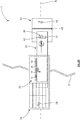
- the device 1 comprises a first measuring element 20, a second measuring element 30 and a retaining element 40. It is fixed at a point A and a point B of a surface on either side of a crack 8 and makes it possible to measure the variation in length between the point A and the point B in a measurement direction 5.
- the device 1 can be fixed on a wall, a ceiling or a floor or in a pluck formed by the intersection of two wall sections, the intersection of a ceiling and a section of wall or the intersection of a floor and a wall section.
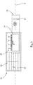
- the first measuring element 20 is a support comprising graduations with millimeter precision in the measuring direction 5, a reading window 21 and a table 22. It also comprises at least one orifice 29 allowing the passage of a screw, for example, for its attachment to the point A. It may include in particular two orifices 29 allowing the passage of screws, the fixing at two distinct points of the support preventing any rotational movement of the support.
- the second measuring element 30 is a strip comprising a vernier with a precision of one tenth of a millimeter and a slot 31.
- the slot 31 is an oblong hole elongated in a direction orthogonal to the measurement direction 5.
- the oblong hole 31 may for example be obtained by drilling and then moving in a direction perpendicular to the measuring direction 5 of a bur in the thickness of the strip 30.
- the graduations of the support 20 opposite the vernier of the slider 30 form measuring means 25 which allow easy reading with a precision to the tenth of a millimeter, reliable and without risk of error of measuring the relative displacement in translation of the slider 30 with respect to the support 20.
- Table 22 on slide 30 allows to enter different data such as measurements made over time or general observations on the evolution of the crack 8.
- the support 20 and the strip 30 may be manufactured using any material sufficiently rigid and resistant to variations in humidity and / or temperature.
- the material must have a low coefficient of linear expansion.
- the material may be for example extruded PVC or polycarbonate.
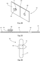
- the retaining element 40 may be manufactured in particular by a method of injection molding of plastic material.
- the plastic material used is a polypropylene, a polyamide or any other polymer commonly used for its plastic properties by those skilled in the art.
- the retaining element 40 comprises a base 43 on which is disposed a stud 41, itself surmounted by a cleat 42. It also comprises at least one orifice 49 allowing the passage of a screw, for example, for fixing it in point B. It may include in particular two orifices 49 allowing the passage of screws, the fixing at two distinct points of the retaining element preventing any rotational movement of the support. Said at least one orifice 49 may be provided by the injection mold or if it is not provided by the injection mold to be pierced in the injected part.
- the stud 41 is a straight cylinder whose base has a diameter substantially equal to but less than the width of the oblong hole 31 and whose height is greater than the thickness of the strip 30.
- a connecting element 35 is formed by the stud 41 sliding in the oblong hole 31 only in a direction orthogonal to the measuring direction 5.
- the connecting element 35 makes it possible to perform a reliable and error-free measurement of the variation of length between the point A and the point B in the measurement direction 5 even in the case where A and B are no longer aligned in the measuring direction 5.
- the connecting element 35 also ensures the integrity of the device 1.
- the cleat 42 is a rectangular parallelepiped having a width less than the diameter of the oblong hole 31 and a length strictly greater than the width of the oblong hole 31. It also has a doubly strange face. Its particular shape makes the connecting element 35 easily removable. Indeed, according to a first orientation of the retaining element 40, the cleat 42 can pass through the aperture 31. According to other orientations of the retaining element 40, in particular by rotating 90.degree. the axis of revolution of the stud 41, the cleat 42 on the contrary forms a stop.
- the retaining element 40 further comprises a groove 45 disposed on the base 43 between the stud 41 and the orifice 49.
- the groove 45 may be provided by the injection mold or if it is not provided by the mold injection be obtained by standard techniques of removal of material or punching on the injected part.
- the retainer 40 may then be bent at the groove as needed to allow attachment of the device 1 to points A and B.
Landscapes
- Physics & Mathematics (AREA)
- General Physics & Mathematics (AREA)
- Length-Measuring Instruments Using Mechanical Means (AREA)
- A Measuring Device Byusing Mechanical Method (AREA)
Description
Le domaine de l'invention est celui de la mesure unidirectionnelle de la variation de longueur entre un point A et un point B d'au moins une surface.The field of the invention is that of the unidirectional measurement of the variation in length between a point A and a point B of at least one surface.
Des dispositifs, tel que celui décrit dans la présente invention, sont notamment utilisés dans le domaine du bâtiment, pour pouvoir contrôler la stabilité d'une façade d'un bâtiment, en mesurer l'évolution, et prévenir ainsi un éventuel danger. Ces dispositifs sont généralement fixés sur des murs pour mesurer l'évolution d'une fissure par exemple.Devices, such as that described in the present invention, are particularly used in the field of building, to control the stability of a facade of a building, measure their evolution, and thus prevent a possible danger. These devices are generally fixed on walls to measure the evolution of a crack, for example.
Une fissure se caractérise par un plan de fissure et un front de fissure. Elle peut évoluer selon trois modes qui peuvent éventuellement se combiner : un mode dit d'ouverture dans lequel le déplacement est perpendiculaire au plan de la fissure, un mode dit de glissement plan dans lequel le déplacement est parallèle au plan de la fissure et normal au front de fissure et un mode dit de glissement anti-plan dans lequel le déplacement est parallèle au plan de la fissure et au front de fissure.A crack is characterized by a crack plane and a crack front. It can evolve in three modes that can possibly be combined: a so-called opening mode in which the displacement is perpendicular to the plane of the crack, a so-called plane slip mode in which the displacement is parallel to the plane of the crack and normal to the crack front and a so-called anti-plane slip mode in which the displacement is parallel to the plane of the crack and the crack front.
Il est connu de l'art antérieur, notamment par la demande de brevet déposée par la demanderesse publiée sous le numéro
Ces deux dispositifs de l'art antérieur présentent l'avantage d'offrir une solution peu coûteuse, facile à mettre en place et ne nécessitant pratiquement aucun savoir faire lors de leur utilisation contrairement à d'autres dispositifs tels que les témoins en plâtre, les règles optiques, les dilatomètres à palpeurs ou les jauges de contraintes. Cependant, un inconvénient de ces deux dispositifs est qu'ils ne peuvent pas être utilisés pour mesurer des variations de longueur de fissures évoluant selon des modes combinés. En effet, étant donné que la réglette coulisse dans le support selon une direction de mesure déterminée, toute évolution de la fissure ayant une composante dans un plan orthogonal à la direction de mesure provoque des contraintes sur le dispositif de mesure. Dans le meilleur des cas, ces contraintes induisent une déformation plastique du dispositif et par conséquent une incertitude sur la fiabilité des valeurs de mesure du dispositif. Dans le pire des cas, ces contraintes induisent la perte d'intégrité du dispositif de mesure qui devient alors inutilisable. Un autre inconvénient de ces deux dispositifs de l'art antérieur est qu'il peut être compliqué de les installer pour mesurer l'évolution d'une fissure se trouvant dans une cueillie, c'est à dire entre deux pans de murs, ou entre un pan de mur et un plafond ou encore entre un pan de mur et un plancher. En effet, dans ce cas, une pièce supplémentaire telle une cornière, éventuellement fabriquée sur mesure, doit être utilisée avec le dispositif et les moyens de fixation.These two devices of the prior art have the advantage of offering an inexpensive solution that is easy to set up and requires practically no know-how when it is used, unlike other devices such as plaster controls, optical rules, probe dilatometers or strain gages. However, a The disadvantage of these two devices is that they can not be used to measure crack length variations in combination modes. Indeed, since the slider slides in the support in a determined measurement direction, any evolution of the crack having a component in a plane orthogonal to the measurement direction causes constraints on the measuring device. In the best case, these constraints induce a plastic deformation of the device and consequently an uncertainty on the reliability of the measurement values of the device. In the worst case, these constraints induce the loss of integrity of the measuring device which then becomes unusable. Another disadvantage of these two devices of the prior art is that it can be complicated to install them to measure the evolution of a crack in a plucked, that is to say between two sections of walls, or between a wall and a ceiling or between a wall and a floor. Indeed, in this case, an additional piece such a bracket, possibly made to measure, must be used with the device and the fastening means.
Le document
Le document
Le document
Le document
Le document
L'invention a pour objectif de pallier au moins un des inconvénients ci-dessus énoncés.The invention aims to overcome at least one of the disadvantages mentioned above.
Plus précisément un objectif de l'invention est de proposer un dispositif de mesure unidirectionnelle de la variation de longueur entre un point A et un point B d'au moins une surface qui soit fiable et qui reste utilisable malgré une variation de position des points A et B dans une direction orthogonale à la direction de mesure.More precisely, an object of the invention is to propose a device for unidirectionally measuring the variation in length between a point A and a point B of at least one surface which is reliable and which remains usable despite a variation of position of the points A and B in a direction orthogonal to the measurement direction.
Un autre objectif de l'invention est de proposer un dispositif de mesure unidirectionnelle de la variation de longueur entre un point A et un point B d'au moins une surface qui soit fiable et qui reste utilisable quelque soit la variation de position desdits points A et B.Another object of the invention is to propose a device for unidirectionally measuring the variation in length between a point A and a point B of at least one surface which is reliable and which remains usable regardless of the variation of position of said points A and B.
Un autre objectif de l'invention est de proposer un dispositif de mesure unidirectionnelle de la variation de longueur entre un point A et un point B d'au moins une surface qui soit peu coûteux, pratique et facile à installer par quiconque.Another object of the invention is to provide a device for unidirectionally measuring the variation in length between a point A and a point B of at least one surface that is inexpensive, practical and easy to install by anyone.
Un autre objectif de l'invention est, au moins selon un mode de réalisation, de proposer un dispositif de mesure unidirectionnelle de la variation de longueur entre un point A et un point B qui puisse être fixé à toutes les surfaces couramment rencontrées dans le domaine du bâtiment.Another object of the invention is, at least according to one embodiment, to propose a device for unidirectionally measuring the variation in length between a point A and a point B that can be fixed to all the surfaces commonly encountered in the field. of the building.
L'invention concerne un dispositif pour mesurer la variation de longueur entre un point A et un point B d'au moins une surface selon une direction de mesure. On entend par « surface » la partie externe d'un matériau, le matériau pouvant être apte à se déformer plastiquement ou apte à se déformer élastiquement ou apte à la propagation de fissures. Dans le domaine du bâtiment ladite au moins une surface est généralement un pan de mur, un plafond ou un plancher, qui sont formés de matériaux peu déformables plastiquement ou élastiquement et dans lesquels peuvent se propager des fissures. Le dispositif selon l'invention comporte un premier élément de mesure destiné à être fixé au point A et un deuxième élément de mesure, chacun possédant des moyens de mesure du déplacement relatif en translation selon ladite direction de mesure dudit premier élément de mesure par rapport audit deuxième élément de mesure. Le dispositif comporte en outre un élément de retenue destiné à être fixé au point B et coopérant avec le deuxième élément de mesure par un élément de liaison, ledit élément de liaison comportant un pion coulissant dans une lumière ayant deux flancs parallèles s'étendant dans une direction orthogonale à ladite direction de mesure. On entend par « lumière » tout orifice ménagé dans une pièce afin d'y permettre le passage d'une autre pièce. La lumière selon l'invention permet le passage du pion. L'écartement entre les deux flancs parallèles s'étendant dans une direction orthogonale à ladite direction de mesure définit la « largeur de la lumière ». Selon une caractéristique préférentielle de l'invention, la lumière a une forme oblongue ou rectangulaire.The invention relates to a device for measuring the variation in length between a point A and a point B of at least one surface in a measurement direction. The term "surface" means the outer part of a material, the material may be able to plastically deform or be able to deform elastically or capable of propagation of cracks. In the field of building, said at least one surface is generally a wall section, a ceiling or a floor, which are formed of materials that are not plastically or elastically deformable and in which cracks can propagate. The device according to the invention comprises a first measuring element intended to be fixed at the point A and a second measuring element, each having means for measuring the relative displacement in translation along said measurement direction of said first measuring element with respect to said measuring element. second measuring element. The device further comprises a retaining element intended to be fixed at the point B and cooperating with the second measuring element by a connecting element, the said connecting element comprising a slider in a lumen having two parallel flanks extending in a direction orthogonal to said measurement direction. The term "light" means any opening in a room to allow the passage of another room. The light according to the invention allows the passage of the pin. The spacing between the two parallel flanks extending in a direction orthogonal to said measurement direction defines the "width of the light". According to a preferred feature of the invention, the light has an oblong or rectangular shape.
Le pion selon l'invention peut être de différentes formes dans la mesure où l'une de ces formes est adaptée pour permettre un coulissement du pion au travers de ladite lumière selon une direction orthogonale à la direction de mesure. Selon une caractéristique préférentielle de l'invention le pion est un cylindre ou un parallélépipède rectangle.The pin according to the invention may be of different forms insofar as one of these forms is adapted to allow sliding of the pin through said light in a direction orthogonal to the measurement direction. According to a preferred feature of the invention the pin is a cylinder or a rectangular parallelepiped.
L'élément de liaison comportant un pion coulissant dans une lumière ayant des flancs parallèles s'étendant dans une direction orthogonale à ladite direction de mesure a un degré de liberté nul en translation selon ladite direction de mesure. Selon une caractéristique préférentielle de l'invention, l'élément de liaison comporte un pion de forme cylindrique coulissant dans une lumière oblongue, le diamètre de section du pion étant sensiblement égal mais inférieur à la largeur de la lumière. Selon une autre caractéristique préférentielle de l'invention, l'élément de liaison comporte un pion de forme parallélépipédique rectangle coulissant dans une lumière rectangulaire, la largeur de section du pion étant sensiblement égale mais inférieure à la largeur de la lumière. Au sens de l'invention, « sensiblement égal » peut être interprété par l'homme de l'art comme étant une différence d'ordre micrométrique afin de permettre un coulissement du pion au travers de la lumière selon une direction orthogonale à la direction de mesure mais ne laissant aucun jeu entre le pion et la lumière selon la direction de mesure.The connecting element comprising a sliding pin in a slot having parallel flanks extending in a direction orthogonal to said measurement direction has a zero degree of freedom in translation along said measurement direction. According to a preferred feature of the invention, the connecting element comprises a cylindrical pin sliding in an oblong slot, the section diameter of the pin being substantially equal to but less than the width of the light. According to another preferred feature of the invention, the connecting element comprises a rectangular parallelepiped shaped pin sliding in a rectangular light, the section width of the pin being substantially equal to but less than the width of the light. Within the meaning of the invention, "substantially equal" can be interpreted by those skilled in the art as a difference of micrometric order to allow a sliding of the pin through the light in a direction orthogonal to the direction of measure but leaving no clearance between the pawn and the light according to the direction of measurement.
Selon une caractéristique préférentielle de l'invention la lumière est disposée dans l'épaisseur du deuxième élément de mesure et le pion est disposé sur ledit élément de retenue. Ceci a pour avantage de permettre une adaptation facile des dispositifs existants tels que ceux décrits dans
Selon l'invention, le pion est surmonté d'un taquet. Le taquet a une longueur dans ladite direction de mesure de dimension supérieure à la largeur dans ladite direction de mesure de ladite lumière. Il permet de limiter l'amplitude du coulissement du pion au travers de la lumière en formant butée. Le taquet a, de manière préférée, une forme adaptée pour passer à travers ladite lumière selon au moins une orientation. Ceci a pour avantage de rendre amovible l'élément de liaison selon la présente invention. Selon un mode de réalisation particulier, le taquet est une sphère de diamètre sensiblement égal mais supérieur à la largeur de ladite lumière : il ne peut alors passer à travers ladite lumière qu'en y étant introduit ou en y étant retiré par forçage.According to the invention, the pin is surmounted by a cleat. The cleat has a length in said measuring direction larger than the width in said measurement direction of said light. It makes it possible to limit the amplitude of the sliding of the pin through the light by forming a stop. The cleat is preferably shaped to fit through said lumen in at least one orientation. This has the advantage of making the connecting element according to the present invention removable. According to a particular embodiment, the cleat is a sphere of diameter substantially equal to but greater than the width of said light: it can then pass through said light by being introduced or by being removed by forcing.
Selon une autre caractéristique préférentielle de l'invention, l'élément de retenue comporte au moins une rainure permettant un pliage dudit élément de retenue. L'élément de retenue peut alors être plié en fonction du besoin pour permettre de fixer le dispositif selon l'invention à la plupart des surfaces couramment rencontrées dans le domaine du bâtiment, sans avoir recours à une pièce supplémentaire, telle une cornière. L'élément de retenue peut alors être plié en fonction du besoin pour permettre de fixer le dispositif selon l'invention dans une cueillie. L'élément de retenue est fabriqué de manière avantageuse dans un polymère ayant des propriétés plastiques tel qu'un polypropylène ou un polyamide. Tout autre polymère utilisé de manière usuelle par l'homme de l'art pour ses propriétés plastiques peut également être utilisé.According to another preferred feature of the invention, the retaining element comprises at least one groove for folding said retaining element. The retaining element can then be folded according to the need to allow fixing the device according to the invention to most commonly encountered surfaces in the field of the building, without the use of an additional part, such as an angle. The retaining element can then be folded according to the need to allow to fix the device according to the invention in a plucked. The retainer is advantageously made of a polymer having plastic properties such as polypropylene or polyamide. Any other polymer conventionally used by those skilled in the art for its plastic properties may also be used.
Selon l'invention, l'un desdits premier et deuxième éléments de mesure est une réglette coulissant dans un support, ledit support étant l'autre desdits premier et deuxième éléments de mesure. Lesdits moyens de mesure permettent de faire des mesures avec une précision donnée, en centimètre, en millimètre, en dixième de millimètres ou en tout autre unité de longueur. Lesdits moyens de mesure peuvent être constitués par des graduations portées sur ledit support selon la direction de mesure, en regard desquelles est placé un vernier disposé sur ladite réglette, tel que décrit dans la demande
Selon une autre caractéristique préférentielle de l'invention, ledit premier élément de mesure et/ou ledit deuxième élément de mesure comporte(nt) un tableau réservé à l'inscription des mesures de relevé.According to another preferred feature of the invention, said first measurement element and / or said second measurement element comprises (nt) a table reserved for recording measurement measurements.
Selon une autre caractéristique préférentielle de l'invention, le premier élément de mesure et/ou l'élément de retenue comporte(nt) au moins un orifice pour le passage de moyens d'ancrage, tel des clous ou des vis associés ou non à des chevilles.According to another preferred feature of the invention, the first measuring element and / or the retaining element comprises (nt) at least one orifice for the passage of anchoring means, such as nails or screws associated or not with ankles.
L'invention concerne également un kit pour la mesure unidirectionnelle de la variation de longueur entre un point A et un point B d'au moins une surface selon une direction de mesure, ce kit comportant un dispositif pour la mesure unidirectionnelle de la variation de longueur entre un point A et un point B d'au moins une surface selon une direction de mesure et des moyens de fixation permettant de fixer le dispositif auxdits points A et B.The invention also relates to a kit for unidirectionally measuring the variation in length between a point A and a point B of at least one surface in a measurement direction, this kit comprising a device for the unidirectional measurement of the variation in length. between a point A and a point B of at least one surface in a direction of measurement and fixing means for fixing the device at said points A and B.
Les moyens de fixation peuvent comprendre des adhésifs. Les adhésifs sont avantageusement choisis en fonction de leur propriété de faible fluage, malgré des contraintes tangentielles importantes, afin de ne pas fausser la fiabilité des mesures. Les adhésifs peuvent notamment être un élément auto-adhésif double face ou une colle. Alternativement, les moyens de fixation peuvent comprendre des moyens d'ancrage dans ladite au moins une surface. Les moyens d'ancrage sont avantageusement choisis pour empêcher toute rotation du premier élément de mesure fixé au point A et de l'élément de retenue fixé au point B.The fastening means may comprise adhesives. The adhesives are advantageously chosen as a function of their low creep property, despite significant tangential stresses, so as not to distort the reliability of the measurements. The adhesives may in particular be a double-sided self-adhesive element or an adhesive. Alternatively, the fixing means may comprise anchoring means in said at least one surface. The anchoring means are advantageously chosen to prevent any rotation of the first measuring element fixed at point A and the retention element fixed at point B.
D'autres caractéristiques et avantages de l'invention apparaîtront plus clairement à la lecture de la description suivante d'un mode de réalisation particulier, donné à titre de simple exemple illustratif et non limitatif, et des dessins annexés, parmi lesquels :
- La
figure 1 représente un premier élément de mesure et un deuxième élément de mesure selon l'invention ; - La
figure 2A est une vue en perspective d'un élément de retenue selon l'invention. - La
figure 2B est une coupe en vue de profil de l'élément de retenue de lafigure 2A ; - La
figure 3A représente un dispositif comprenant le premier élément de mesure et le deuxième élément de mesure de lafigure 1 et l'élément de retenue de lafigure 2A , fixé en un point A et un point B d'une surface de part et d'autre d'une fissure ; - La
figure 3B représente l'élément de liaison du dispositif de lafigure 3A .
- The
figure 1 represents a first measuring element and a second measuring element according to the invention; - The
Figure 2A is a perspective view of a retaining element according to the invention. - The
Figure 2B is a cross sectional view of the restraint element of theFigure 2A ; - The
figure 3A represents a device comprising the first measuring element and the second measuring element of thefigure 1 and the retaining element of theFigure 2A fixed at a point A and a point B of a surface on either side of a crack; - The
figure 3B represents the connecting element of the device of thefigure 3A .
En référence aux
Le premier élément de mesure 20 est un support comportant des graduations avec une précision au millimètre selon la direction de mesure 5, une fenêtre de lecture 21 et un tableau 22. Il comporte également au moins un orifice 29 permettant le passage d'une vis, par exemple, pour sa fixation au point A. Il peut notamment comporter deux orifices 29 permettant le passage de vis, la fixation en deux points distincts du support empêchant tout mouvement de rotation du support.The
Le deuxième élément de mesure 30 est une réglette comportant un vernier avec une précision au dixième de millimètre et une lumière 31. La lumière 31 est un trou oblong allongé dans une direction orthogonale à la direction de mesure 5. Le trou oblong 31 peut par exemple être obtenu par un perçage puis un déplacement dans une direction perpendiculaire à la direction de mesure 5 d'une fraise dans l'épaisseur de la réglette 30.The
Les graduations du support 20 en regard du vernier de la réglette 30 forment des moyens de mesure 25 qui permettent une lecture facile avec une précision au dixième de millimètre, fiable et sans risque d'erreur de la mesure du déplacement relatif en translation de la réglette 30 par rapport au support 20.The graduations of the
Le tableau 22 sur la réglette 30 permet d'inscrire différentes données comme les mesures faites au cours du temps ou les observations générales sur l'évolution de la fissure 8.Table 22 on
Le support 20 et la réglette 30 peuvent être fabriqués à l'aide de tout matériau suffisamment rigide et résistant à des variations d'humidité et/ou de température. En particulier le matériau doit présenter un faible coefficient de dilatation linéaire. Le matériau peut être par exemple du PVC extrudé ou du polycarbonate.The
L'élément de retenue 40 peut être fabriqué notamment par un procédé de moulage par injection de matériau plastique. Le matériau plastique utilisé est un polypropylène, un polyamide ou tout autre polymère utilisé de manière usuelle pour ses propriétés plastiques par l'homme de l'art.The retaining
L'élément de retenue 40 comporte une base 43 sur laquelle est disposée un plot 41, lui-même surmonté d'un taquet 42. Il comporte également au moins un orifice 49 permettant le passage d'une vis, par exemple, pour sa fixation au point B. Il peut notamment comporter deux orifices 49 permettant le passage de vis, la fixation en deux points distincts de l'élément de retenue empêchant tout mouvement de rotation du support. Ledit au moins un orifice 49 peut être prévu par le moule d'injection ou s'il n'est pas prévu par le moule d'injection être percé dans la pièce injectée.The retaining
Le plot 41 est un cylindre droit dont la base a un diamètre sensiblement égal mais inférieur à la largeur du trou oblong 31 et dont la hauteur est supérieure à l'épaisseur de la réglette 30. Un élément de liaison 35 est formé par le plot 41 coulissant dans le trou oblong 31 uniquement selon une direction orthogonale à la direction de mesure 5. L'élément de liaison 35 permet de réaliser une mesure fiable et sans risque d'erreur de la variation de longueur entre le point A et le point B selon la direction de mesure 5 même dans le cas où A et B ne sont plus alignés selon la direction de mesure 5. L'élément de liaison 35 permet également d'assurer l'intégrité du dispositif 1. Le taquet 42 est un parallélépipède rectangle ayant une largeur inférieure au diamètre du trou oblong 31 et une longueur strictement supérieure à la largeur du trou oblong 31. Il a de plus une face doublement bizeautée. Sa forme particulière permet de rendre l'élément de liaison 35 facilement amovible. En effet, selon une première orientation de l'élément de retenue 40, le taquet 42 peut passer au travers de la lumière 31. Selon d'autres orientations de l'élément de retenue 40, notamment par rotation de 90° par rapport à l'axe de révolution du plot 41, le taquet 42 forme au contraire une butée.The
L'élément de retenue 40 comporte en outre une rainure 45 disposée sur la base 43 entre le plot 41 et l'orifice 49. La rainure 45 peut être prévue par le moule d'injection ou si elle n'est pas prévue par le moule d'injection être obtenue par des techniques usuelles d'enlèvement de matière ou de poinçonnage sur la pièce injectée. L'élément de retenue 40 peut alors être plié au niveau de la rainure en fonction du besoin pour permettre de fixer le dispositif 1 aux points A et B.The retaining
Claims (9)
- Device (1) for measuring the change in length between a point A and a point B of at least one surface in one measurement direction (5), comprising a first measurement element (20) intended to be fastened at said point A and a second measurement element (30), said first measurement element (20) and said second measurement element (30) having means (25) of measuring the relative movement in translation in said measurement direction (5) of said first measurement element (20) relative to said second measurement element (30), one of said first measurement element (20) and second measurement element (30) being a ruler sliding in a holder, said holder being the other of said first measurement element (20) and second measurement element (30), characterised in that said device (1) further comprises a retaining element (40) intended to be fastened at said point B and engaging with said second measurement element (30) via a connection element (35), said connection element (35) comprising a pin (41) sliding in an opening (31) having two parallel flanks extending in a direction perpendicular to said measurement direction (5), said pin (41) having mounted thereon a tab (42) for limiting the amplitude of sliding of said pin (41) through said opening (31) forming a stop thereof, said tab (42) being of a length in said measurement direction (5) greater than the width in said measurement direction (5) of said opening (31).
- Device (1) according to Claim 1, characterised in that said opening (31) is of an oblong or rectangular shape.
- Device (1) according to either of the preceding claims, characterised in that said tab (42) is of a shape adapted for passing through said opening (31) in at least one orientation.
- Device (1) according to any one of the preceding claims, characterised in that said tab (42) is a sphere of a diameter substantially equal to but greater than the width of said opening (31).
- Device (1) according to any one of the preceding claims, characterised in that said opening (31) is arranged in the body of said second measurement element (30) and said pin (41) is arranged on said retaining element (40).
- Device (1) according to any one of the preceding claims, characterised in that said retaining element (40) comprises at least one groove (45) allowing said retaining element (40) to be bent.
- Device (1) according to any one of the preceding claims, characterised in that said first measurement element (20) and/or said second measurement element (30) comprise(s) a table (22) dedicated to the recorded measurements.
- Device (1) according to any one of the preceding claims, characterised in that said first measurement element (20) and/or said retaining element (40) comprise(s) at least one aperture (29, 49) for the passage of anchoring means such as screws or nails, said screws or nails being associated with wall plugs or not.
- Kit for unidirectional measurement of the development of a crack on at least one surface, characterised in that it comprises at least:- a device (1) according to any one of the preceding claims,- fastening means selected from adhesives or anchoring means whereby said device (1) can be fastened at said points A and B.
Applications Claiming Priority (1)
| Application Number | Priority Date | Filing Date | Title |
|---|---|---|---|
| FR1654940A FR3051895A1 (en) | 2016-05-31 | 2016-05-31 | DEVICE FOR THE UNIDIRECTIONAL MEASUREMENT OF THE VARIATION OF LENGTH BETWEEN TWO POINTS OF A SURFACE |
Publications (2)
| Publication Number | Publication Date |
|---|---|
| EP3252425A1 EP3252425A1 (en) | 2017-12-06 |
| EP3252425B1 true EP3252425B1 (en) | 2018-12-12 |
Family
ID=56684058
Family Applications (1)
| Application Number | Title | Priority Date | Filing Date |
|---|---|---|---|
| EP17172575.7A Active EP3252425B1 (en) | 2016-05-31 | 2017-05-23 | Device for unidirectional measurement of the change in length between two points of a surface |
Country Status (2)
| Country | Link |
|---|---|
| EP (1) | EP3252425B1 (en) |
| FR (1) | FR3051895A1 (en) |
Family Cites Families (6)
| Publication number | Priority date | Publication date | Assignee | Title |
|---|---|---|---|---|
| GB2110372B (en) * | 1981-11-13 | 1985-10-16 | Roger William Johnson | Monitoring cracks in buildings |
| CH683277A5 (en) * | 1991-06-19 | 1994-02-15 | Reto Martinelli Karl Menti | Wall ties. |
| DE9400755U1 (en) * | 1994-01-18 | 1994-03-10 | PPW-Polyplan Werkzeuge GmbH, 22457 Hamburg | Crack detector for buildings |
| FR2784178B1 (en) * | 1998-10-01 | 2000-11-24 | Janpierre Saugnac | DEVICE FOR MEASURING THE CHANGE IN THE DISTANCE BETWEEN A FIRST POINT AND A SECOND POINT OF A STRUCTURE |
| FR2884911B1 (en) * | 2005-04-25 | 2007-10-26 | Janpierre Saugnac | DEVICE FOR MEASURING THE EVOLUTION OF A FIXED AND DEPENDENTLY FIXED CRACK ON A WALL AND CORRESPONDING ASSEMBLY |
| PL212870B1 (en) * | 2007-08-31 | 2012-12-31 | Neostrain Spolka Z Ograniczona Odpowiedzialnoscia | Device for measurement of scratch spacing width, cracks and gaps in building objects |
-
2016
- 2016-05-31 FR FR1654940A patent/FR3051895A1/en active Pending
-
2017
- 2017-05-23 EP EP17172575.7A patent/EP3252425B1/en active Active
Also Published As
| Publication number | Publication date |
|---|---|
| EP3252425A1 (en) | 2017-12-06 |
| FR3051895A1 (en) | 2017-12-01 |
Similar Documents
| Publication | Publication Date | Title |
|---|---|---|
| EP3449208B1 (en) | Device for measuring endogenous deformations | |
| FR2940437A1 (en) | TOOL, TOOL ASSEMBLY, AND METHOD OF ADJUSTING THE FLANGE OF BLADES OF A MODEL PROPELLER | |
| EP3252425B1 (en) | Device for unidirectional measurement of the change in length between two points of a surface | |
| EP3333317A1 (en) | Railway rail guiding system | |
| EP1945881A1 (en) | Method for mounting blades on a supporting structure and improved fixing element | |
| FR2992063A1 (en) | DEVICE FOR MEASURING CORROSION IN A METAL STRUCTURE OR COMPRISING AT LEAST ONE METALLIC FRAME, USES AND METHOD THEREFOR | |
| EP1244918A1 (en) | Device for angular positioning of a vaned angle-of-attack sensor on an aircraft wall | |
| BR112013012705B1 (en) | METHOD AND DEVICE FOR INSPECTING THE THREADING SURFACE OF A TUBULAR CONNECTION USED IN THE PETROLEUM INDUSTRY | |
| EP2795141B1 (en) | System enabling the attachment of an object to an element having attachment groove(s), and attachment device for such a system | |
| CA3104029A1 (en) | Bracing device for securing a facing | |
| EP2102585B1 (en) | Device and method for measuring the mechanical deformations of a section | |
| WO2018073036A1 (en) | Device indicating the loosening of a nut | |
| EP3423780A1 (en) | Strain sensor with measurement discrimination according to the deformation direction | |
| FR2680711A1 (en) | METHOD FOR PERMANENT BENDING OF DEFORMABLE BODIES. | |
| WO2015104265A1 (en) | Multizone piezoelectric road sensor | |
| EP3445529B1 (en) | Accessory for centring tools on a machining appliance, centring method and centring assistance device comprising such an accessory | |
| FR3108650A1 (en) | Fixing device for a carpentry frame | |
| FR2942538A1 (en) | Hinge moment measuring device for e.g. control surface, of model aircraft, has connection cords connecting reference and measuring plates, where cords are arranged for forming pivoting axis fixed with respect to reference plate | |
| FR2570487A1 (en) | Apparatus for measuring the diameters of cylindrical articles | |
| EP3724604B1 (en) | Improved inertial unit with suspended inertial device | |
| FR2665527A2 (en) | Device for measuring the variation in the opening of a crack, including a remote measurement dial | |
| FR3041007A1 (en) | DEVICE FOR MAINTAINING A REMOTE ENCLOSURE ELEMENT OF A VAPOR BARRIER MEMBRANE AND CONSTRUCTIVE SYSTEM WITH DOUBLE FRAME COMPRISING SUCH A DEVICE | |
| EP1887316B1 (en) | Device for the measurement of deformations of a profile subject to one or more forces | |
| EP2410287B1 (en) | Device for measuring and reading distances in millimetres and fractions of millimetres | |
| FR2899680A1 (en) | LINEAR MEASURING DEVICE OR ARTICULATED METER WITH RODS WITH MAGNETS |
Legal Events
| Date | Code | Title | Description |
|---|---|---|---|
| PUAI | Public reference made under article 153(3) epc to a published international application that has entered the european phase |
Free format text: ORIGINAL CODE: 0009012 |
|
| STAA | Information on the status of an ep patent application or granted ep patent |
Free format text: STATUS: THE APPLICATION HAS BEEN PUBLISHED |
|
| AK | Designated contracting states |
Kind code of ref document: A1 Designated state(s): AL AT BE BG CH CY CZ DE DK EE ES FI FR GB GR HR HU IE IS IT LI LT LU LV MC MK MT NL NO PL PT RO RS SE SI SK SM TR |
|
| AX | Request for extension of the european patent |
Extension state: BA ME |
|
| STAA | Information on the status of an ep patent application or granted ep patent |
Free format text: STATUS: REQUEST FOR EXAMINATION WAS MADE |
|
| 17P | Request for examination filed |
Effective date: 20180205 |
|
| RBV | Designated contracting states (corrected) |
Designated state(s): AL AT BE BG CH CY CZ DE DK EE ES FI FR GB GR HR HU IE IS IT LI LT LU LV MC MK MT NL NO PL PT RO RS SE SI SK SM TR |
|
| GRAP | Despatch of communication of intention to grant a patent |
Free format text: ORIGINAL CODE: EPIDOSNIGR1 |
|
| STAA | Information on the status of an ep patent application or granted ep patent |
Free format text: STATUS: GRANT OF PATENT IS INTENDED |
|
| RIC1 | Information provided on ipc code assigned before grant |
Ipc: G01B 5/30 20060101ALI20180601BHEP Ipc: E04G 23/00 20060101ALI20180601BHEP Ipc: G01B 5/14 20060101AFI20180601BHEP |
|
| INTG | Intention to grant announced |
Effective date: 20180625 |
|
| GRAS | Grant fee paid |
Free format text: ORIGINAL CODE: EPIDOSNIGR3 |
|
| GRAA | (expected) grant |
Free format text: ORIGINAL CODE: 0009210 |
|
| STAA | Information on the status of an ep patent application or granted ep patent |
Free format text: STATUS: THE PATENT HAS BEEN GRANTED |
|
| AK | Designated contracting states |
Kind code of ref document: B1 Designated state(s): AL AT BE BG CH CY CZ DE DK EE ES FI FR GB GR HR HU IE IS IT LI LT LU LV MC MK MT NL NO PL PT RO RS SE SI SK SM TR |
|
| REG | Reference to a national code |
Ref country code: GB Ref legal event code: FG4D Free format text: NOT ENGLISH |
|
| REG | Reference to a national code |
Ref country code: CH Ref legal event code: EP |
|
| REG | Reference to a national code |
Ref country code: AT Ref legal event code: REF Ref document number: 1076601 Country of ref document: AT Kind code of ref document: T Effective date: 20181215 |
|
| REG | Reference to a national code |
Ref country code: DE Ref legal event code: R096 Ref document number: 602017001335 Country of ref document: DE |
|
| REG | Reference to a national code |
Ref country code: IE Ref legal event code: FG4D Free format text: LANGUAGE OF EP DOCUMENT: FRENCH |
|
| REG | Reference to a national code |
Ref country code: NL Ref legal event code: MP Effective date: 20181212 |
|
| REG | Reference to a national code |
Ref country code: LT Ref legal event code: MG4D |
|
| PG25 | Lapsed in a contracting state [announced via postgrant information from national office to epo] |
Ref country code: FI Free format text: LAPSE BECAUSE OF FAILURE TO SUBMIT A TRANSLATION OF THE DESCRIPTION OR TO PAY THE FEE WITHIN THE PRESCRIBED TIME-LIMIT Effective date: 20181212 Ref country code: HR Free format text: LAPSE BECAUSE OF FAILURE TO SUBMIT A TRANSLATION OF THE DESCRIPTION OR TO PAY THE FEE WITHIN THE PRESCRIBED TIME-LIMIT Effective date: 20181212 Ref country code: NO Free format text: LAPSE BECAUSE OF FAILURE TO SUBMIT A TRANSLATION OF THE DESCRIPTION OR TO PAY THE FEE WITHIN THE PRESCRIBED TIME-LIMIT Effective date: 20190312 Ref country code: LV Free format text: LAPSE BECAUSE OF FAILURE TO SUBMIT A TRANSLATION OF THE DESCRIPTION OR TO PAY THE FEE WITHIN THE PRESCRIBED TIME-LIMIT Effective date: 20181212 Ref country code: ES Free format text: LAPSE BECAUSE OF FAILURE TO SUBMIT A TRANSLATION OF THE DESCRIPTION OR TO PAY THE FEE WITHIN THE PRESCRIBED TIME-LIMIT Effective date: 20181212 Ref country code: LT Free format text: LAPSE BECAUSE OF FAILURE TO SUBMIT A TRANSLATION OF THE DESCRIPTION OR TO PAY THE FEE WITHIN THE PRESCRIBED TIME-LIMIT Effective date: 20181212 Ref country code: BG Free format text: LAPSE BECAUSE OF FAILURE TO SUBMIT A TRANSLATION OF THE DESCRIPTION OR TO PAY THE FEE WITHIN THE PRESCRIBED TIME-LIMIT Effective date: 20190312 |
|
| REG | Reference to a national code |
Ref country code: AT Ref legal event code: MK05 Ref document number: 1076601 Country of ref document: AT Kind code of ref document: T Effective date: 20181212 |
|
| PG25 | Lapsed in a contracting state [announced via postgrant information from national office to epo] |
Ref country code: AL Free format text: LAPSE BECAUSE OF FAILURE TO SUBMIT A TRANSLATION OF THE DESCRIPTION OR TO PAY THE FEE WITHIN THE PRESCRIBED TIME-LIMIT Effective date: 20181212 Ref country code: SE Free format text: LAPSE BECAUSE OF FAILURE TO SUBMIT A TRANSLATION OF THE DESCRIPTION OR TO PAY THE FEE WITHIN THE PRESCRIBED TIME-LIMIT Effective date: 20181212 Ref country code: GR Free format text: LAPSE BECAUSE OF FAILURE TO SUBMIT A TRANSLATION OF THE DESCRIPTION OR TO PAY THE FEE WITHIN THE PRESCRIBED TIME-LIMIT Effective date: 20190313 Ref country code: RS Free format text: LAPSE BECAUSE OF FAILURE TO SUBMIT A TRANSLATION OF THE DESCRIPTION OR TO PAY THE FEE WITHIN THE PRESCRIBED TIME-LIMIT Effective date: 20181212 |
|
| PG25 | Lapsed in a contracting state [announced via postgrant information from national office to epo] |
Ref country code: NL Free format text: LAPSE BECAUSE OF FAILURE TO SUBMIT A TRANSLATION OF THE DESCRIPTION OR TO PAY THE FEE WITHIN THE PRESCRIBED TIME-LIMIT Effective date: 20181212 |
|
| PG25 | Lapsed in a contracting state [announced via postgrant information from national office to epo] |
Ref country code: CZ Free format text: LAPSE BECAUSE OF FAILURE TO SUBMIT A TRANSLATION OF THE DESCRIPTION OR TO PAY THE FEE WITHIN THE PRESCRIBED TIME-LIMIT Effective date: 20181212 Ref country code: PT Free format text: LAPSE BECAUSE OF FAILURE TO SUBMIT A TRANSLATION OF THE DESCRIPTION OR TO PAY THE FEE WITHIN THE PRESCRIBED TIME-LIMIT Effective date: 20190412 Ref country code: PL Free format text: LAPSE BECAUSE OF FAILURE TO SUBMIT A TRANSLATION OF THE DESCRIPTION OR TO PAY THE FEE WITHIN THE PRESCRIBED TIME-LIMIT Effective date: 20181212 Ref country code: IT Free format text: LAPSE BECAUSE OF FAILURE TO SUBMIT A TRANSLATION OF THE DESCRIPTION OR TO PAY THE FEE WITHIN THE PRESCRIBED TIME-LIMIT Effective date: 20181212 |
|
| PG25 | Lapsed in a contracting state [announced via postgrant information from national office to epo] |
Ref country code: EE Free format text: LAPSE BECAUSE OF FAILURE TO SUBMIT A TRANSLATION OF THE DESCRIPTION OR TO PAY THE FEE WITHIN THE PRESCRIBED TIME-LIMIT Effective date: 20181212 Ref country code: IS Free format text: LAPSE BECAUSE OF FAILURE TO SUBMIT A TRANSLATION OF THE DESCRIPTION OR TO PAY THE FEE WITHIN THE PRESCRIBED TIME-LIMIT Effective date: 20190412 Ref country code: SM Free format text: LAPSE BECAUSE OF FAILURE TO SUBMIT A TRANSLATION OF THE DESCRIPTION OR TO PAY THE FEE WITHIN THE PRESCRIBED TIME-LIMIT Effective date: 20181212 Ref country code: RO Free format text: LAPSE BECAUSE OF FAILURE TO SUBMIT A TRANSLATION OF THE DESCRIPTION OR TO PAY THE FEE WITHIN THE PRESCRIBED TIME-LIMIT Effective date: 20181212 Ref country code: SK Free format text: LAPSE BECAUSE OF FAILURE TO SUBMIT A TRANSLATION OF THE DESCRIPTION OR TO PAY THE FEE WITHIN THE PRESCRIBED TIME-LIMIT Effective date: 20181212 |
|
| REG | Reference to a national code |
Ref country code: DE Ref legal event code: R097 Ref document number: 602017001335 Country of ref document: DE |
|
| PLBE | No opposition filed within time limit |
Free format text: ORIGINAL CODE: 0009261 |
|
| STAA | Information on the status of an ep patent application or granted ep patent |
Free format text: STATUS: NO OPPOSITION FILED WITHIN TIME LIMIT |
|
| PG25 | Lapsed in a contracting state [announced via postgrant information from national office to epo] |
Ref country code: DK Free format text: LAPSE BECAUSE OF FAILURE TO SUBMIT A TRANSLATION OF THE DESCRIPTION OR TO PAY THE FEE WITHIN THE PRESCRIBED TIME-LIMIT Effective date: 20181212 Ref country code: AT Free format text: LAPSE BECAUSE OF FAILURE TO SUBMIT A TRANSLATION OF THE DESCRIPTION OR TO PAY THE FEE WITHIN THE PRESCRIBED TIME-LIMIT Effective date: 20181212 Ref country code: SI Free format text: LAPSE BECAUSE OF FAILURE TO SUBMIT A TRANSLATION OF THE DESCRIPTION OR TO PAY THE FEE WITHIN THE PRESCRIBED TIME-LIMIT Effective date: 20181212 |
|
| 26N | No opposition filed |
Effective date: 20190913 |
|
| PG25 | Lapsed in a contracting state [announced via postgrant information from national office to epo] |
Ref country code: MC Free format text: LAPSE BECAUSE OF FAILURE TO SUBMIT A TRANSLATION OF THE DESCRIPTION OR TO PAY THE FEE WITHIN THE PRESCRIBED TIME-LIMIT Effective date: 20181212 |
|
| REG | Reference to a national code |
Ref country code: BE Ref legal event code: MM Effective date: 20190531 |
|
| PG25 | Lapsed in a contracting state [announced via postgrant information from national office to epo] |
Ref country code: LU Free format text: LAPSE BECAUSE OF NON-PAYMENT OF DUE FEES Effective date: 20190523 |
|
| PG25 | Lapsed in a contracting state [announced via postgrant information from national office to epo] |
Ref country code: TR Free format text: LAPSE BECAUSE OF FAILURE TO SUBMIT A TRANSLATION OF THE DESCRIPTION OR TO PAY THE FEE WITHIN THE PRESCRIBED TIME-LIMIT Effective date: 20181212 |
|
| PG25 | Lapsed in a contracting state [announced via postgrant information from national office to epo] |
Ref country code: IE Free format text: LAPSE BECAUSE OF NON-PAYMENT OF DUE FEES Effective date: 20190523 |
|
| PG25 | Lapsed in a contracting state [announced via postgrant information from national office to epo] |
Ref country code: BE Free format text: LAPSE BECAUSE OF NON-PAYMENT OF DUE FEES Effective date: 20190531 |
|
| PG25 | Lapsed in a contracting state [announced via postgrant information from national office to epo] |
Ref country code: CH Free format text: LAPSE BECAUSE OF NON-PAYMENT OF DUE FEES Effective date: 20200531 Ref country code: LI Free format text: LAPSE BECAUSE OF NON-PAYMENT OF DUE FEES Effective date: 20200531 |
|
| PG25 | Lapsed in a contracting state [announced via postgrant information from national office to epo] |
Ref country code: CY Free format text: LAPSE BECAUSE OF FAILURE TO SUBMIT A TRANSLATION OF THE DESCRIPTION OR TO PAY THE FEE WITHIN THE PRESCRIBED TIME-LIMIT Effective date: 20181212 |
|
| PG25 | Lapsed in a contracting state [announced via postgrant information from national office to epo] |
Ref country code: MT Free format text: LAPSE BECAUSE OF FAILURE TO SUBMIT A TRANSLATION OF THE DESCRIPTION OR TO PAY THE FEE WITHIN THE PRESCRIBED TIME-LIMIT Effective date: 20181212 Ref country code: HU Free format text: LAPSE BECAUSE OF FAILURE TO SUBMIT A TRANSLATION OF THE DESCRIPTION OR TO PAY THE FEE WITHIN THE PRESCRIBED TIME-LIMIT; INVALID AB INITIO Effective date: 20170523 |
|
| GBPC | Gb: european patent ceased through non-payment of renewal fee |
Effective date: 20210523 |
|
| PG25 | Lapsed in a contracting state [announced via postgrant information from national office to epo] |
Ref country code: GB Free format text: LAPSE BECAUSE OF NON-PAYMENT OF DUE FEES Effective date: 20210523 |
|
| REG | Reference to a national code |
Ref country code: FR Ref legal event code: PLFP Year of fee payment: 6 |
|
| PG25 | Lapsed in a contracting state [announced via postgrant information from national office to epo] |
Ref country code: MK Free format text: LAPSE BECAUSE OF FAILURE TO SUBMIT A TRANSLATION OF THE DESCRIPTION OR TO PAY THE FEE WITHIN THE PRESCRIBED TIME-LIMIT Effective date: 20181212 |
|
| REG | Reference to a national code |
Ref country code: DE Ref legal event code: R081 Ref document number: 602017001335 Country of ref document: DE Owner name: SAUGNAC JAUGES, FR Free format text: FORMER OWNER: PRYL, GIEZ, FR |
|
| PGFP | Annual fee paid to national office [announced via postgrant information from national office to epo] |
Ref country code: DE Payment date: 20240524 Year of fee payment: 8 |
|
| PGFP | Annual fee paid to national office [announced via postgrant information from national office to epo] |
Ref country code: FR Payment date: 20240523 Year of fee payment: 8 |