EP3252386A1 - Outdoor unit of air conditioner - Google Patents
Outdoor unit of air conditioner Download PDFInfo
- Publication number
- EP3252386A1 EP3252386A1 EP17172525.2A EP17172525A EP3252386A1 EP 3252386 A1 EP3252386 A1 EP 3252386A1 EP 17172525 A EP17172525 A EP 17172525A EP 3252386 A1 EP3252386 A1 EP 3252386A1
- Authority
- EP
- European Patent Office
- Prior art keywords
- panel
- housing
- bell mouth
- top panel
- blower
- Prior art date
- Legal status (The legal status is an assumption and is not a legal conclusion. Google has not performed a legal analysis and makes no representation as to the accuracy of the status listed.)
- Granted
Links
Images




Classifications
-
- F—MECHANICAL ENGINEERING; LIGHTING; HEATING; WEAPONS; BLASTING
- F24—HEATING; RANGES; VENTILATING
- F24F—AIR-CONDITIONING; AIR-HUMIDIFICATION; VENTILATION; USE OF AIR CURRENTS FOR SCREENING
- F24F1/00—Room units for air-conditioning, e.g. separate or self-contained units or units receiving primary air from a central station
- F24F1/06—Separate outdoor units, e.g. outdoor unit to be linked to a separate room comprising a compressor and a heat exchanger
- F24F1/38—Fan details of outdoor units, e.g. bell-mouth shaped inlets or fan mountings
-
- F—MECHANICAL ENGINEERING; LIGHTING; HEATING; WEAPONS; BLASTING
- F24—HEATING; RANGES; VENTILATING
- F24F—AIR-CONDITIONING; AIR-HUMIDIFICATION; VENTILATION; USE OF AIR CURRENTS FOR SCREENING
- F24F1/00—Room units for air-conditioning, e.g. separate or self-contained units or units receiving primary air from a central station
- F24F1/06—Separate outdoor units, e.g. outdoor unit to be linked to a separate room comprising a compressor and a heat exchanger
- F24F1/56—Casing or covers of separate outdoor units, e.g. fan guards
- F24F1/58—Separate protective covers for outdoor units, e.g. solar guards, snow shields or camouflage
-
- F—MECHANICAL ENGINEERING; LIGHTING; HEATING; WEAPONS; BLASTING
- F24—HEATING; RANGES; VENTILATING
- F24F—AIR-CONDITIONING; AIR-HUMIDIFICATION; VENTILATION; USE OF AIR CURRENTS FOR SCREENING
- F24F1/00—Room units for air-conditioning, e.g. separate or self-contained units or units receiving primary air from a central station
- F24F1/06—Separate outdoor units, e.g. outdoor unit to be linked to a separate room comprising a compressor and a heat exchanger
- F24F1/46—Component arrangements in separate outdoor units
- F24F1/48—Component arrangements in separate outdoor units characterised by air airflow, e.g. inlet or outlet airflow
- F24F1/50—Component arrangements in separate outdoor units characterised by air airflow, e.g. inlet or outlet airflow with outlet air in upward direction
-
- F—MECHANICAL ENGINEERING; LIGHTING; HEATING; WEAPONS; BLASTING
- F24—HEATING; RANGES; VENTILATING
- F24F—AIR-CONDITIONING; AIR-HUMIDIFICATION; VENTILATION; USE OF AIR CURRENTS FOR SCREENING
- F24F13/00—Details common to, or for air-conditioning, air-humidification, ventilation or use of air currents for screening
- F24F13/20—Casings or covers
Definitions
- the present invention relates to an outdoor unit of an air conditioner, and more particularly to an upward blow-out type outdoor unit in which a blower chamber is disposed on a top portion of a machine chamber which includes a heat exchanger and a compressor.
- a multi-type air conditioner in which a plurality of indoor units are connected to a single outdoor unit is an example of an air conditioner.
- the outdoor unit of the air conditioner includes a rectangular parallelepiped housing, and the inner portion of the housing is partitioned into a machine chamber which includes a heat exchanger and a compressor, and a blower chamber which includes a blower.
- the machine chamber is disposed on the bottom portion of the housing, the blower chamber is disposed on the top portion of the machine chamber, and a top panel which includes an air blowing port of the blower is provided on the top surface of the housing.
- the top panel is horizontally bridged across and fixed to support columns (or left and right side panels) which are provided to stand on four corners of the housing, and a fan guard for protecting the blower is attached to the air blowing port.
- the top panel is supported only at the four corners, when a person stands on the top panel, when an object falls onto the top panel, or the like and a great load is applied, the top panel and the fan guard may easily deform.
- the air blowing port is formed in the center of the top panel, the mechanical strength is weak, and the top panel easily flexes in the vicinity of the center portion.
- An object of the present invention is to provide an outdoor unit of an air conditioner which receives a load which is applied to a top panel using an entirety of a housing, and the top panel and a fan guard do not easily deform.
- One aspect of the present invention relates to an outdoor unit of an air conditioner which includes a blower and a bell mouth of the blower disposed in an inner portion of a housing, in which a top panel having an air blowing port of the blower is provided on the top surface of the housing.
- a lower end of the bell mouth is fixed to a frame of the housing, an upper end of the bell mouth is disposed so as to come into contact with a circumference of the air blowing port on a back face of the top panel, and a portion of a load which is applied to the top panel is supported by the bell mouth.
- the bell mouth includes a cylindrical body portion which is disposed on an outer circumference of the blower, an upper flange is formed on an upper end of the body portion, and the upper flange comes into contact with a back face along the back face of the top panel.
- a frame of the housing includes a base panel, a left side panel and a right side panel which are disposed along a left side end and a right side end of the base panel, a front beam which is bridged between front ends of the left side panel and the right side panel, and a rear beam which is bridged between rear ends of the left side panel and the right side panel, and in which a lower end of the bell mouth is supported by the front beam and the rear beam.
- the top panel and the fan guard do not deform easily.
- an outdoor unit 1 of an air conditioner includes a rectangular parallelepiped housing 2 which is horizontally long in the left-right direction (the left-right direction in Fig. 1 ), and the inner portion of the housing 2 is partitioned into a machine chamber MC which includes a heat exchanger 3, a compressor, and the like (not illustrated), and a blower chamber FC which includes a blower 4.
- the machine chamber MC is disposed on the bottom portion inside the housing 2, and the blower chamber FC is disposed above the machine chamber MC.
- the housing 2 is provided with a base panel 20, a left side panel 21L, a right side panel 21R, a front beam 22F (refer to Fig. 3 ), and a rear beam 22R (refer to Fig. 3 ) as a basic frame F.
- the base panel 20 is installed on an installation surface and has a longitudinal shape, the left side panel 21L is provided to stand on the left side end of the base panel 20, the right side panel 21R is provided to stand on the right side end of the base panel 20, the front beam 22F is horizontally bridged between the front end of the left side panel 21L and the front end of the right side panel 21R, and the rear beam 22R is horizontally bridged between the rear end of the left side panel 21L and the rear end of the right side panel 21R.
- the front beam 22F and the rear beam 22R are disposed on the heat exchanger 3 of the machine chamber MC of the housing 2 to form a boundary with the blower chamber FC.
- the front beam 22F and the rear beam 22R are horizontally disposed to be parallel to the base panel 20 and to be parallel on the same horizontal plane as each other.
- a front panel 26 is attached to the front face of the machine chamber MC of the housing 2.
- the front panel 26 is a horizontally long metal panel which blocks the front face of the machine chamber MC, both left and right ends of the front panel 26 are screwed to the front end of the left side panel 21L and the right side panel 21R, the upper end side is screwed to a top panel 23, and the lower end side is screwed to the front beam 22F.
- a rear panel (not illustrated) which is similar to the front panel 26 is attached to the rear face side of the blower chamber FC of the housing 2.
- the rear panel is a horizontally long metal panel which blocks the rear face of the blower chamber FC, both left and right ends of the rear panel are screwed to the rear end of the left side panel 21L and the right side panel 21R, the upper end side of the rear panel is screwed to the top panel 23, and the lower end side is screwed to the rear beam 22R.
- the front beam 22F is formed in a single rail shape by press molding a single sheet of metal plate.
- a supporting portion 221 which supports a bell mouth 5 (described later) is formed on the upper end side of the front beam 22F.
- the lower end portion of the front beam 22F is bent in approximately a right angle toward the inside (the inside of the housing 2), and forms a supporting piece 227 which supports a beam member 411 of a motor bracket 41 (described later).
- the supporting portion 221 is provided with a horizontal supporting surface 222, a front face rib 223, and a rear face rib 224.
- the supporting surface 222 continuously extends to the left and right of the upper end of the front beam 22F, the front face rib 223 is provided to stand substantially perpendicular from the front end (the rear end in Fig. 8A ) of the supporting surface 222, and the rear face rib 224 is provided to stand substantially perpendicular from the rear end (the front end in Fig. 8A ) of the supporting surface 222.
- the front face rib 223 is continuously formed along both left and right ends of the front beam 22F.
- two cutout portions 225 and 225 are provided in two locations at positions so as to be left-right symmetrical interposing a rotation shaft 421 of the blower 4 of the front face rib 223.
- the rear face rib 224 is disposed in two locations at positions which interpose the supporting surface 222 and face each of the cutout portions 225 and 225 of the front face rib 223, and a female screw hole 226 for screwing in the bell mouth 5 is provided by being bored into the middle of the rear face rib 224 at each location at which the rear face rib 224 is provided.
- the motor bracket 41 on which the blower 4 is mounted is provided on the front beam 22F and the rear beam 22R.
- the motor bracket 41 includes a pair of beam members 411 and 411 which are bridged between the front beam 22F and the rear beam 22R in parallel.
- the front ends of the beam members 411 and 411 abut a rear face 228 ( Figs. 8A to 8C ) of the front beam 22F, and are screwed in a state of being placed on the supporting piece 227.
- the rear ends of the beam members 411 and 411 are similarly screwed in a state of abutting against the rear beam.
- a fan motor 42 of the blower 4 is mounted on the motor bracket 41, and a propeller fan 43 is attached to a rotation shaft 421 of the fan motor 42.
- the bell mouth 5 of the blower 4 is further provided in the blower chamber FC.
- the bell mouth 5 includes a rectangular stand portion 51 and a cylindrical body portion 52 which is provided to protrude from the top surface of the stand portion 51 upward, and is disposed to surround the outer circumference of the propeller fan 43.
- the stand portion 51 has a hollow rectangular box shape, and the lower face of the stand portion 51 is open over the full surface.
- Both a front wall surface 51F (the surface positioned on the front face side of the housing 2) and a rear wall surface 51R (the surface positioned on the rear face side of the housing 2) of the stand portion 51 are formed as perpendicular surfaces (surfaces which are perpendicular to the top surface of the stand portion 51) which continue along the left and right, and a center portion 511 is formed so as to overhang to the front face side from a left wall portion 512L and a right wall portion 512R via stepped surfaces 513 and 513.
- the left wall portion 512L and the right wall portion 512R are provided with screw holes 514 to be screwed together with the female screw holes 226 of the rear face ribs 224 (refer to Fig. 8B ).
- the screw holes 514 are screw insertion holes, and are provided in a total of four locations, one in each of the left wall portions 512L and the right wall portion 512R of the front wall surface 51F and the left wall portions 512L and the right wall portion 512R of the rear wall surface 51R.
- a lower flange 515 which extends horizontally toward the outside is formed on a lower end 516 of the stand portion 51. Accordingly, as illustrated in Fig. 7 , the lower flange 515 is mounted along the supporting surface 222 of the supporting portion 221.
- the body portion 52 is formed in an approximately straight cylindrical shape from the stand portion 51 to the attachment position of the propeller fan 43, and the opening diameter of the body portion 52 is formed to gradually become larger from the upper end of the propeller fan 43 toward a top end opening 521 (the top end in Fig. 3 ).
- An upper flange 53 is formed on the top end of the body portion 52 so as to be inclined from the upper end of the body portion 52 toward the outside.
- the upper flange 53 includes a first upper flange 531 and a second upper flange 532, and the width of the first upper flange 531 is formed bigger than the width of the second upper flange 532.
- the first upper flange 531 is provided to protrude toward the left-right direction (the left-right direction in Fig. 3 ) of the body portion 52
- the second upper flange 532 is provided to protrude toward the front-rear direction (the front-rear direction in Fig. 3 ) of the body portion 52.
- the first upper flange 531 is parallel to the top surface of the stand portion 51.
- the second upper flange 532 is formed to be diagonally inclined.
- the second upper flange 532 may have a shape with which it is possible to come into contact along a back face 233 of the top panel 23, and as long as it is possible to support the load of the top panel 23, the shape of the second upper flange 532 may be arbitrarily modified according to the specification.
- the outer circumference of the side face of the body portion 52 is provided with reinforcing ribs 54 for increasing the mechanical strength of the body portion 52.
- the reinforcing ribs 54 are formed on the side face of the body portion 52 so as to be parallel to each other in an up-down direction, and in the embodiment, and are provided in four locations on each of the left and right side faces (a total of eight locations).
- the top panel 23 is bridged between the top end of the left side panel 21L and the upper end of the right side panel 21R.
- the top panel 23 is a metal panel which blocks the top surface of the housing 2, and an air blowing port 11 of the blower 4 is formed in the center of the top panel 23.
- the air blowing port 11 is formed to match the top end opening 521 of the body portion 52, as illustrated in Figs. 6 and 7 , the upper flange 53 of the body portion 52 is configured to come into contact with the rear face (the back face 233) of the top panel 23.
- a fan guard attachment portion 231 to which a fan guard 6 (described later) is screwed is provided on the top panel 23.
- the fan guard attachment portion 231 is a concave portion which is formed a level lower to match the outer shape of the fan guard 6 from the top surface of the top panel 23 in the periphery of the air blowing port 11.
- screw holes 232 are provided in three locations on each of the left and right sides of the fan guard attachment portion 231.
- the fan guard attachment portion 231 is formed such that the depth thereof is greater (deeper) than the thickness of the fan guard 6, and the fan guard 6 is stored inside the fan guard attachment portion 231 so as not to protrude from the surface of the top panel 23 to the outside.
- the fan guard 6 includes a lateral rail portion 61, a longitudinal rail portion 62, and a left-right pair of fixing plates 63.
- the lateral rail portion 61 extends in the left-right direction of the top panel 23 and is formed from a plurality of wire rods which are disposed parallel to each other at a predetermined interval
- the longitudinal rail portion 62 extends in the front-rear direction of the top panel 23 and is formed from a plurality of wire rods which are disposed parallel to each other at a predetermined interval
- the fixing plates 63 continuously extend from the front end to the rear end of both left and right end portions of the lateral rail portion 61.
- the lateral rail portion 61 and the longitudinal rail portion 62 are both formed from plastic coated wire rods (soft steel wire rods, the surfaces of which are coated with a polyvinyl chloride resin) and are designed such that the diameter of the wire rods of the lateral rail portion 61 is greater than the diameter of the wire rods of the longitudinal rail portion 62. Accordingly, it is possible to increase the mechanical strength of the fan guard 6, and it is possible to prevent deformation of the fan guard 6.
- the longitudinal rail portion 62 is disposed on the top surface of (above in Fig. 6 ) the lateral rail portion 61, and after welding the intersecting portions of the longitudinal rail portion 62 and the lateral rail portion 61, the surfaces thereof are coated with a vinyl chloride resin.
- the fixing method, the fixing locations, and the coating process of the lateral rail portion 61 and the longitudinal rail portion 62 are arbitrarily modifiable according to the specifications.
- auxiliary rail portions 611 are provided on the center portion of the fan guard 6 parallel along the lateral rail portion 61 and at a predetermined interval between the wire rods of the lateral rail portion 61. Although blown air does not leave from the center portion of the propeller fan 43, there is a case in which a vortex is generated.
- the auxiliary rail portion 611 is provided in order to suppress the occurrence of a vortex.
- the top panel 23 supports not only the left side panel 21L and the right side panel 21R, but also comes into contact with and supports the upper end of the bell mouth 5 with the periphery of the air blowing port 11 of the top panel 23, and it is possible to support the load which is applied to the top panel 23 using the housing 2 by fixing the lower end of the bell mouth 5 to the front beam 22F and the rear beam 22R which are a frame F of the housing 2.
- the present invention by supporting the load which is applied to the top panel via the bell mouth using the housing, even if a large load such as a person or an object is applied to the top panel, the top panel and the fan guard do not deform easily.
Landscapes
- Engineering & Computer Science (AREA)
- Chemical & Material Sciences (AREA)
- Combustion & Propulsion (AREA)
- Mechanical Engineering (AREA)
- General Engineering & Computer Science (AREA)
- Other Air-Conditioning Systems (AREA)
- Structures Of Non-Positive Displacement Pumps (AREA)
Abstract
Description
- The present invention relates to an outdoor unit of an air conditioner, and more particularly to an upward blow-out type outdoor unit in which a blower chamber is disposed on a top portion of a machine chamber which includes a heat exchanger and a compressor.
- A multi-type air conditioner in which a plurality of indoor units are connected to a single outdoor unit is an example of an air conditioner. For example, as described in
Japanese Patent No. 5402987 - The top panel is horizontally bridged across and fixed to support columns (or left and right side panels) which are provided to stand on four corners of the housing, and a fan guard for protecting the blower is attached to the air blowing port.
- However, since the top panel is supported only at the four corners, when a person stands on the top panel, when an object falls onto the top panel, or the like and a great load is applied, the top panel and the fan guard may easily deform. In particular, since the air blowing port is formed in the center of the top panel, the mechanical strength is weak, and the top panel easily flexes in the vicinity of the center portion.
- An object of the present invention is to provide an outdoor unit of an air conditioner which receives a load which is applied to a top panel using an entirety of a housing, and the top panel and a fan guard do not easily deform.
- One aspect of the present invention relates to an outdoor unit of an air conditioner which includes a blower and a bell mouth of the blower disposed in an inner portion of a housing, in which a top panel having an air blowing port of the blower is provided on the top surface of the housing. A lower end of the bell mouth is fixed to a frame of the housing, an upper end of the bell mouth is disposed so as to come into contact with a circumference of the air blowing port on a back face of the top panel, and a portion of a load which is applied to the top panel is supported by the bell mouth.
- As a more preferable aspect, the bell mouth includes a cylindrical body portion which is disposed on an outer circumference of the blower, an upper flange is formed on an upper end of the body portion, and the upper flange comes into contact with a back face along the back face of the top panel.
- As a still more preferable aspect, a frame of the housing includes a base panel, a left side panel and a right side panel which are disposed along a left side end and a right side end of the base panel, a front beam which is bridged between front ends of the left side panel and the right side panel, and a rear beam which is bridged between rear ends of the left side panel and the right side panel, and in which a lower end of the bell mouth is supported by the front beam and the rear beam.
- According to an aspect of the present invention, by supporting a portion of the load which is applied to the top panel via the bell mouth, even if a large load such as a person or an object is applied to the top panel, the top panel and the fan guard do not deform easily.
-
-
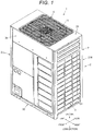
Fig. 1 is a perspective view of an outdoor unit of an air conditioner according to an embodiment of the present invention. -
Fig. 2 is a plan view of the outdoor unit of the air conditioner. -
Fig. 3 is an exploded perspective view in which a portion of the outdoor unit of the air conditioner is exploded. -
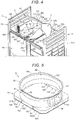
Fig. 4 is an enlarged perspective view of a blower chamber of the outdoor unit of the air conditioner. -
Fig. 5 is an enlarged perspective view of a bell mouth of the outdoor unit of the air conditioner. -
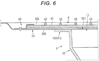
Fig. 6 is a sectional view taken along an A-A line portion ofFig. 2 . -
Fig. 7 is a sectional view of a B-B line portion ofFig. 2 . -
Fig. 8A is a perspective view of a front beam.Fig. 8B is a perspective view illustrating a state in which the bell mouth is mounted on a front beam.Fig. 8C is a plan view. - Next, description will be given of an embodiment of the present invention with reference to the drawings; however, the present invention is not limited thereto.
- As illustrated in
Figs. 1 to 3 , anoutdoor unit 1 of an air conditioner includes a rectangularparallelepiped housing 2 which is horizontally long in the left-right direction (the left-right direction inFig. 1 ), and the inner portion of thehousing 2 is partitioned into a machine chamber MC which includes aheat exchanger 3, a compressor, and the like (not illustrated), and a blower chamber FC which includes ablower 4. In the embodiment, the machine chamber MC is disposed on the bottom portion inside thehousing 2, and the blower chamber FC is disposed above the machine chamber MC. - The
housing 2 is provided with abase panel 20, aleft side panel 21L, aright side panel 21R, afront beam 22F (refer toFig. 3 ), and arear beam 22R (refer toFig. 3 ) as a basic frame F. Thebase panel 20 is installed on an installation surface and has a longitudinal shape, theleft side panel 21L is provided to stand on the left side end of thebase panel 20, theright side panel 21R is provided to stand on the right side end of thebase panel 20, thefront beam 22F is horizontally bridged between the front end of theleft side panel 21L and the front end of theright side panel 21R, and therear beam 22R is horizontally bridged between the rear end of theleft side panel 21L and the rear end of theright side panel 21R. - In the embodiment, the
front beam 22F and therear beam 22R are disposed on theheat exchanger 3 of the machine chamber MC of thehousing 2 to form a boundary with the blower chamber FC. Thefront beam 22F and therear beam 22R are horizontally disposed to be parallel to thebase panel 20 and to be parallel on the same horizontal plane as each other. - A
front panel 26 is attached to the front face of the machine chamber MC of thehousing 2. Thefront panel 26 is a horizontally long metal panel which blocks the front face of the machine chamber MC, both left and right ends of thefront panel 26 are screwed to the front end of theleft side panel 21L and theright side panel 21R, the upper end side is screwed to atop panel 23, and the lower end side is screwed to thefront beam 22F. - A rear panel (not illustrated) which is similar to the
front panel 26 is attached to the rear face side of the blower chamber FC of thehousing 2. The rear panel is a horizontally long metal panel which blocks the rear face of the blower chamber FC, both left and right ends of the rear panel are screwed to the rear end of theleft side panel 21L and theright side panel 21R, the upper end side of the rear panel is screwed to thetop panel 23, and the lower end side is screwed to therear beam 22R. - Since the basic structure of the
front beam 22F and therear beam 22R is the same, hereinafter description will be given of thefront beam 22F. With reference toFigs. 8A to 8C , thefront beam 22F is formed in a single rail shape by press molding a single sheet of metal plate. A supportingportion 221 which supports a bell mouth 5 (described later) is formed on the upper end side of thefront beam 22F. The lower end portion of thefront beam 22F is bent in approximately a right angle toward the inside (the inside of the housing 2), and forms a supportingpiece 227 which supports abeam member 411 of a motor bracket 41 (described later). - The supporting
portion 221 is provided with a horizontal supportingsurface 222, afront face rib 223, and arear face rib 224. The supportingsurface 222 continuously extends to the left and right of the upper end of thefront beam 22F, thefront face rib 223 is provided to stand substantially perpendicular from the front end (the rear end inFig. 8A ) of the supportingsurface 222, and therear face rib 224 is provided to stand substantially perpendicular from the rear end (the front end inFig. 8A ) of the supportingsurface 222. - The
front face rib 223 is continuously formed along both left and right ends of thefront beam 22F. In the embodiment, twocutout portions rotation shaft 421 of theblower 4 of thefront face rib 223. - The
rear face rib 224 is disposed in two locations at positions which interpose the supportingsurface 222 and face each of thecutout portions front face rib 223, and afemale screw hole 226 for screwing in thebell mouth 5 is provided by being bored into the middle of therear face rib 224 at each location at which therear face rib 224 is provided. - As illustrated in
Fig. 8B , themotor bracket 41 on which theblower 4 is mounted is provided on thefront beam 22F and therear beam 22R. Themotor bracket 41 includes a pair ofbeam members front beam 22F and therear beam 22R in parallel. The front ends of thebeam members Figs. 8A to 8C ) of thefront beam 22F, and are screwed in a state of being placed on the supportingpiece 227. The rear ends of thebeam members - A
fan motor 42 of theblower 4 is mounted on themotor bracket 41, and apropeller fan 43 is attached to arotation shaft 421 of thefan motor 42. Thebell mouth 5 of theblower 4 is further provided in the blower chamber FC. - As illustrated in
Fig. 5 , thebell mouth 5 includes arectangular stand portion 51 and acylindrical body portion 52 which is provided to protrude from the top surface of thestand portion 51 upward, and is disposed to surround the outer circumference of thepropeller fan 43. - The
stand portion 51 has a hollow rectangular box shape, and the lower face of thestand portion 51 is open over the full surface. Both afront wall surface 51F (the surface positioned on the front face side of the housing 2) and arear wall surface 51R (the surface positioned on the rear face side of the housing 2) of thestand portion 51 are formed as perpendicular surfaces (surfaces which are perpendicular to the top surface of the stand portion 51) which continue along the left and right, and acenter portion 511 is formed so as to overhang to the front face side from aleft wall portion 512L and aright wall portion 512R via steppedsurfaces - The
left wall portion 512L and theright wall portion 512R are provided withscrew holes 514 to be screwed together with the female screw holes 226 of the rear face ribs 224 (refer toFig. 8B ). In the embodiment, the screw holes 514 are screw insertion holes, and are provided in a total of four locations, one in each of theleft wall portions 512L and theright wall portion 512R of thefront wall surface 51F and theleft wall portions 512L and theright wall portion 512R of therear wall surface 51R. - A
lower flange 515 which extends horizontally toward the outside is formed on alower end 516 of thestand portion 51. Accordingly, as illustrated inFig. 7 , thelower flange 515 is mounted along the supportingsurface 222 of the supportingportion 221. - The
body portion 52 is formed in an approximately straight cylindrical shape from thestand portion 51 to the attachment position of thepropeller fan 43, and the opening diameter of thebody portion 52 is formed to gradually become larger from the upper end of thepropeller fan 43 toward a top end opening 521 (the top end inFig. 3 ). - An
upper flange 53 is formed on the top end of thebody portion 52 so as to be inclined from the upper end of thebody portion 52 toward the outside. In the embodiment, theupper flange 53 includes a firstupper flange 531 and a secondupper flange 532, and the width of the firstupper flange 531 is formed bigger than the width of the secondupper flange 532. The firstupper flange 531 is provided to protrude toward the left-right direction (the left-right direction inFig. 3 ) of thebody portion 52, and the secondupper flange 532 is provided to protrude toward the front-rear direction (the front-rear direction inFig. 3 ) of thebody portion 52. - In the embodiment, the first
upper flange 531 is parallel to the top surface of thestand portion 51. As is illustrated inFig. 7 , it is difficult to render the second upper flange 532 a flange shape which is parallel to the top surface of thestand portion 51 due to the constrictions of the housing space. Therefore, the secondupper flange 532 is formed to be diagonally inclined. The secondupper flange 532 may have a shape with which it is possible to come into contact along aback face 233 of thetop panel 23, and as long as it is possible to support the load of thetop panel 23, the shape of the secondupper flange 532 may be arbitrarily modified according to the specification. - The outer circumference of the side face of the
body portion 52 is provided with reinforcingribs 54 for increasing the mechanical strength of thebody portion 52. The reinforcingribs 54 are formed on the side face of thebody portion 52 so as to be parallel to each other in an up-down direction, and in the embodiment, and are provided in four locations on each of the left and right side faces (a total of eight locations). - On the top surface of the housing 2 (the top surface of the blower chamber MC), the
top panel 23 is bridged between the top end of theleft side panel 21L and the upper end of theright side panel 21R. Thetop panel 23 is a metal panel which blocks the top surface of thehousing 2, and anair blowing port 11 of theblower 4 is formed in the center of thetop panel 23. - The
air blowing port 11 is formed to match the top end opening 521 of thebody portion 52, as illustrated inFigs. 6 and7 , theupper flange 53 of thebody portion 52 is configured to come into contact with the rear face (the back face 233) of thetop panel 23. - As illustrated in
Fig. 3 , a fanguard attachment portion 231 to which a fan guard 6 (described later) is screwed is provided on thetop panel 23. The fanguard attachment portion 231 is a concave portion which is formed a level lower to match the outer shape of thefan guard 6 from the top surface of thetop panel 23 in the periphery of theair blowing port 11. In the embodiment, screw holes 232 are provided in three locations on each of the left and right sides of the fanguard attachment portion 231. - Also referring to
Fig. 6 , the fanguard attachment portion 231 is formed such that the depth thereof is greater (deeper) than the thickness of thefan guard 6, and thefan guard 6 is stored inside the fanguard attachment portion 231 so as not to protrude from the surface of thetop panel 23 to the outside. - Next, as is illustrated in
Fig. 6 , thefan guard 6 includes alateral rail portion 61, alongitudinal rail portion 62, and a left-right pair of fixingplates 63. Thelateral rail portion 61 extends in the left-right direction of thetop panel 23 and is formed from a plurality of wire rods which are disposed parallel to each other at a predetermined interval, thelongitudinal rail portion 62 extends in the front-rear direction of thetop panel 23 and is formed from a plurality of wire rods which are disposed parallel to each other at a predetermined interval, and the fixingplates 63 continuously extend from the front end to the rear end of both left and right end portions of thelateral rail portion 61. - In the embodiment, the
lateral rail portion 61 and thelongitudinal rail portion 62 are both formed from plastic coated wire rods (soft steel wire rods, the surfaces of which are coated with a polyvinyl chloride resin) and are designed such that the diameter of the wire rods of thelateral rail portion 61 is greater than the diameter of the wire rods of thelongitudinal rail portion 62. Accordingly, it is possible to increase the mechanical strength of thefan guard 6, and it is possible to prevent deformation of thefan guard 6. - As illustrated in
Fig. 6 , thelongitudinal rail portion 62 is disposed on the top surface of (above inFig. 6 ) thelateral rail portion 61, and after welding the intersecting portions of thelongitudinal rail portion 62 and thelateral rail portion 61, the surfaces thereof are coated with a vinyl chloride resin. The fixing method, the fixing locations, and the coating process of thelateral rail portion 61 and thelongitudinal rail portion 62 are arbitrarily modifiable according to the specifications. - In the embodiment,
auxiliary rail portions 611 are provided on the center portion of thefan guard 6 parallel along thelateral rail portion 61 and at a predetermined interval between the wire rods of thelateral rail portion 61. Although blown air does not leave from the center portion of thepropeller fan 43, there is a case in which a vortex is generated. Theauxiliary rail portion 611 is provided in order to suppress the occurrence of a vortex. - Next, with reference to
Fig. 7 andFigs. 8A to 8C , in order to attach thebell mouth 5 to thehousing 2, place thelower flange 515 of thestand portion 51 of thebell mouth 5 on the top of each of the supportingportions 221 of thefront beam 22F and therear beam 22R, subsequently align the screw holes 514 which are provided in the left and right wall portions 512 with the screw holes 226 of therear face rib 224, and subsequently fix thebell mouth 5 to thehousing 2 using screws (not illustrated). - Next, by screwing both ends of the
top panel 23 into theside panels top panel 23 over the upper end of theleft side panel 21L of thehousing 2 to the top end of theright side panel 21R, theupper flange 53 of thebell mouth 5 comes into contact with the back face 233 (the lower face inFig. 7 ) of thetop panel 23 along the outer circumference of theair blowing port 11. - Accordingly, the
top panel 23 supports not only theleft side panel 21L and theright side panel 21R, but also comes into contact with and supports the upper end of thebell mouth 5 with the periphery of theair blowing port 11 of thetop panel 23, and it is possible to support the load which is applied to thetop panel 23 using thehousing 2 by fixing the lower end of thebell mouth 5 to thefront beam 22F and therear beam 22R which are a frame F of thehousing 2. - As described above, according to the present invention, by supporting the load which is applied to the top panel via the bell mouth using the housing, even if a large load such as a person or an object is applied to the top panel, the top panel and the fan guard do not deform easily.
Claims (3)
- An outdoor unit of an air conditioner comprising:a blower and a bell mouth of the blower disposed in an inner portion of a housing,wherein a top panel having an air blowing port of the blower is provided on a top surface of the housing,wherein a lower end of the bell mouth is fixed to a frame of the housing, an upper end of the bell mouth is disposed so as to come into contact with a circumference of the air blowing port on a back face of the top panel, andwherein a portion of a load which is applied to the top panel is supported by the bell mouth.
- The outdoor unit of an air conditioner according to Claim 1,
wherein the bell mouth includes a cylindrical body portion which is disposed on an outer circumference of the blower,
wherein an upper flange is formed on an upper end of the body portion, and
wherein the upper flange comes into contact with a back face along the back face of the top panel. - The outdoor unit of an air conditioner according to Claim 1 or 2,
wherein a frame of the housing includesa base panel,a left side panel and a right side panel which are disposed along a left side end and a right side end of the base panel,a front beam which is bridged between front ends of the left side panel and the right side panel, anda rear beam which is bridged between rear ends of the left side panel and the right side panel, andwherein a lower end of the bell mouth is supported by the front beam and the rear beam.
Applications Claiming Priority (1)
| Application Number | Priority Date | Filing Date | Title |
|---|---|---|---|
| JP2016108335A JP6849938B2 (en) | 2016-05-31 | 2016-05-31 | Outdoor unit of air conditioner |
Publications (2)
| Publication Number | Publication Date |
|---|---|
| EP3252386A1 true EP3252386A1 (en) | 2017-12-06 |
| EP3252386B1 EP3252386B1 (en) | 2020-09-09 |
Family
ID=58778903
Family Applications (1)
| Application Number | Title | Priority Date | Filing Date |
|---|---|---|---|
| EP17172525.2A Not-in-force EP3252386B1 (en) | 2016-05-31 | 2017-05-23 | Outdoor unit of air conditioner |
Country Status (6)
| Country | Link |
|---|---|
| US (1) | US10386083B2 (en) |
| EP (1) | EP3252386B1 (en) |
| JP (1) | JP6849938B2 (en) |
| CN (1) | CN107449071A (en) |
| AU (1) | AU2017203652B2 (en) |
| ES (1) | ES2823285T3 (en) |
Families Citing this family (6)
| Publication number | Priority date | Publication date | Assignee | Title |
|---|---|---|---|---|
| KR102163905B1 (en) * | 2016-01-25 | 2020-10-12 | 미쓰비시덴키 가부시키가이샤 | Outdoor unit and air conditioner equipped with it |
| US10684054B2 (en) * | 2017-05-22 | 2020-06-16 | Trane International Inc. | Tension support system for motorized fan |
| JP6880321B2 (en) | 2018-06-04 | 2021-06-02 | 三菱電機株式会社 | Blower and refrigeration cycle equipment |
| WO2022064561A1 (en) * | 2020-09-23 | 2022-03-31 | 東芝キヤリア株式会社 | Outdoor unit for air conditioner |
| CN215675544U (en) * | 2021-08-06 | 2022-01-28 | 广东美的暖通设备有限公司 | Wind-guiding circle, air conditioner outdoor unit and air conditioner |
| JPWO2025141685A1 (en) * | 2023-12-26 | 2025-07-03 |
Citations (5)
| Publication number | Priority date | Publication date | Assignee | Title |
|---|---|---|---|---|
| JPS542987B2 (en) | 1975-07-21 | 1979-02-16 | ||
| JP2002221341A (en) * | 2001-01-24 | 2002-08-09 | Daikin Ind Ltd | Outdoor unit of air conditioner |
| EP2056028A2 (en) * | 2007-10-31 | 2009-05-06 | LG Electronics, Inc. | Outdoor unit of air conditioner |
| EP2549194A1 (en) * | 2011-07-19 | 2013-01-23 | Sanyo Electric Co., Ltd. | Fan guard and air conditioner having the same |
| EP2889544A1 (en) * | 2013-12-26 | 2015-07-01 | LG Electronics Inc. | Outdoor unit of air conditioner |
Family Cites Families (18)
| Publication number | Priority date | Publication date | Assignee | Title |
|---|---|---|---|---|
| JPS56146877U (en) * | 1980-04-01 | 1981-11-05 | ||
| JPS5878468U (en) * | 1981-11-24 | 1983-05-27 | 三菱電機株式会社 | Air conditioner outdoor unit |
| JPS60116164U (en) * | 1984-01-12 | 1985-08-06 | 三菱電機株式会社 | air conditioner |
| JPS60130374U (en) * | 1984-02-10 | 1985-08-31 | 三菱電機株式会社 | Outdoor unit for air conditioner |
| JPH10148363A (en) * | 1996-11-20 | 1998-06-02 | Fujitsu General Ltd | Outdoor unit of air conditioner |
| US20090010817A1 (en) * | 2004-10-12 | 2009-01-08 | Ngk Insulators, Ltd. | Honeycomb filter |
| CN100532960C (en) * | 2005-06-30 | 2009-08-26 | 乐金电子(天津)电器有限公司 | Ceiling air conditioner |
| KR101234826B1 (en) * | 2005-10-31 | 2013-02-20 | 삼성전자주식회사 | Outdoor Unit of Air Conditioner |
| KR20090020759A (en) * | 2007-08-24 | 2009-02-27 | 엘지전자 주식회사 | Control box of multi air conditioner |
| JP2009103353A (en) * | 2007-10-23 | 2009-05-14 | Hitachi Appliances Inc | Air conditioner outdoor unit |
| EP2085709A1 (en) * | 2008-01-30 | 2009-08-05 | LG Electronics Inc. | Air conditioner |
| JP5388497B2 (en) * | 2008-07-29 | 2014-01-15 | 日立アプライアンス株式会社 | Blower guide support structure and air conditioner outdoor unit |
| CN101696696B (en) * | 2009-10-27 | 2013-05-15 | 广东志高空调有限公司 | Fan of outdoor unit of air conditioner |
| US9273896B2 (en) * | 2011-05-20 | 2016-03-01 | Daikin Industries, Ltd. | Outdoor unit of refrigerating apparatus |
| JP5402987B2 (en) | 2011-05-20 | 2014-01-29 | ダイキン工業株式会社 | Refrigeration unit outdoor unit |
| JP5929850B2 (en) * | 2013-07-24 | 2016-06-08 | 三菱電機株式会社 | Air conditioner outdoor unit |
| KR102302546B1 (en) * | 2014-12-31 | 2021-09-15 | 엘지전자 주식회사 | Outdoor unit of air conditioner |
| US10801518B2 (en) * | 2016-02-26 | 2020-10-13 | Mitsubishi Electric Corporation | Blower apparatus |
-
2016
- 2016-05-31 JP JP2016108335A patent/JP6849938B2/en active Active
-
2017
- 2017-05-16 US US15/596,725 patent/US10386083B2/en active Active
- 2017-05-23 ES ES17172525T patent/ES2823285T3/en active Active
- 2017-05-23 EP EP17172525.2A patent/EP3252386B1/en not_active Not-in-force
- 2017-05-31 CN CN201710399537.3A patent/CN107449071A/en active Pending
- 2017-05-31 AU AU2017203652A patent/AU2017203652B2/en active Active
Patent Citations (5)
| Publication number | Priority date | Publication date | Assignee | Title |
|---|---|---|---|---|
| JPS542987B2 (en) | 1975-07-21 | 1979-02-16 | ||
| JP2002221341A (en) * | 2001-01-24 | 2002-08-09 | Daikin Ind Ltd | Outdoor unit of air conditioner |
| EP2056028A2 (en) * | 2007-10-31 | 2009-05-06 | LG Electronics, Inc. | Outdoor unit of air conditioner |
| EP2549194A1 (en) * | 2011-07-19 | 2013-01-23 | Sanyo Electric Co., Ltd. | Fan guard and air conditioner having the same |
| EP2889544A1 (en) * | 2013-12-26 | 2015-07-01 | LG Electronics Inc. | Outdoor unit of air conditioner |
Also Published As
| Publication number | Publication date |
|---|---|
| JP2017215080A (en) | 2017-12-07 |
| AU2017203652B2 (en) | 2022-11-03 |
| ES2823285T3 (en) | 2021-05-06 |
| US20170343224A1 (en) | 2017-11-30 |
| US10386083B2 (en) | 2019-08-20 |
| JP6849938B2 (en) | 2021-03-31 |
| AU2017203652A1 (en) | 2017-12-14 |
| EP3252386B1 (en) | 2020-09-09 |
| CN107449071A (en) | 2017-12-08 |
Similar Documents
| Publication | Publication Date | Title |
|---|---|---|
| EP3252386A1 (en) | Outdoor unit of air conditioner | |
| EP3252387B1 (en) | Outdoor unit of air conditioner | |
| EP2787290B1 (en) | Casing for outdoor unit for air conditioning device | |
| JP2011158137A (en) | Outdoor unit of air conditioner | |
| CN106016452A (en) | Ceiling-Embedded Air Conditioner | |
| JP5594168B2 (en) | Air conditioner outdoor unit | |
| JP2008190806A (en) | Outdoor unit of air conditioner | |
| JPH0126998Y2 (en) | ||
| JP7039898B2 (en) | Indoor unit of air conditioner | |
| JP2006226644A (en) | Air conditioner outdoor unit | |
| JP2017009201A (en) | Air conditioner outdoor unit | |
| JP6115856B2 (en) | Outdoor unit | |
| JPH0798130A (en) | Air conditioner outdoor unit | |
| CN217817123U (en) | Casing subassembly and air condensing units | |
| CN205481432U (en) | Motor support and air conditioner | |
| JP2010175195A (en) | Outdoor unit of refrigerating device | |
| CN107355913B (en) | Circuit board mounting structure and air conditioner | |
| JP6867861B2 (en) | Outdoor unit of air conditioner | |
| JP6739002B2 (en) | Air curtain device | |
| JP6439936B2 (en) | Duct type air conditioner | |
| WO2025239336A1 (en) | Outdoor unit for air conditioner and method for assembling outdoor unit for air conditioner | |
| KR200328246Y1 (en) | The lower part reinforcement of refrigerator | |
| JP2009144978A (en) | Air conditioner | |
| CN107676945A (en) | The emergency button box and air conditioner room unit of air conditioner room unit | |
| JP2007206646A (en) | Display device |
Legal Events
| Date | Code | Title | Description |
|---|---|---|---|
| PUAI | Public reference made under article 153(3) epc to a published international application that has entered the european phase |
Free format text: ORIGINAL CODE: 0009012 |
|
| STAA | Information on the status of an ep patent application or granted ep patent |
Free format text: STATUS: THE APPLICATION HAS BEEN PUBLISHED |
|
| AK | Designated contracting states |
Kind code of ref document: A1 Designated state(s): AL AT BE BG CH CY CZ DE DK EE ES FI FR GB GR HR HU IE IS IT LI LT LU LV MC MK MT NL NO PL PT RO RS SE SI SK SM TR |
|
| AX | Request for extension of the european patent |
Extension state: BA ME |
|
| STAA | Information on the status of an ep patent application or granted ep patent |
Free format text: STATUS: REQUEST FOR EXAMINATION WAS MADE |
|
| 17P | Request for examination filed |
Effective date: 20180606 |
|
| RBV | Designated contracting states (corrected) |
Designated state(s): AL AT BE BG CH CY CZ DE DK EE ES FI FR GB GR HR HU IE IS IT LI LT LU LV MC MK MT NL NO PL PT RO RS SE SI SK SM TR |
|
| GRAP | Despatch of communication of intention to grant a patent |
Free format text: ORIGINAL CODE: EPIDOSNIGR1 |
|
| STAA | Information on the status of an ep patent application or granted ep patent |
Free format text: STATUS: GRANT OF PATENT IS INTENDED |
|
| INTG | Intention to grant announced |
Effective date: 20200403 |
|
| INTG | Intention to grant announced |
Effective date: 20200403 |
|
| GRAS | Grant fee paid |
Free format text: ORIGINAL CODE: EPIDOSNIGR3 |
|
| GRAA | (expected) grant |
Free format text: ORIGINAL CODE: 0009210 |
|
| STAA | Information on the status of an ep patent application or granted ep patent |
Free format text: STATUS: THE PATENT HAS BEEN GRANTED |
|
| AK | Designated contracting states |
Kind code of ref document: B1 Designated state(s): AL AT BE BG CH CY CZ DE DK EE ES FI FR GB GR HR HU IE IS IT LI LT LU LV MC MK MT NL NO PL PT RO RS SE SI SK SM TR |
|
| REG | Reference to a national code |
Ref country code: GB Ref legal event code: FG4D |
|
| REG | Reference to a national code |
Ref country code: AT Ref legal event code: REF Ref document number: 1312051 Country of ref document: AT Kind code of ref document: T Effective date: 20200915 Ref country code: CH Ref legal event code: EP |
|
| REG | Reference to a national code |
Ref country code: IE Ref legal event code: FG4D |
|
| REG | Reference to a national code |
Ref country code: DE Ref legal event code: R096 Ref document number: 602017023122 Country of ref document: DE |
|
| REG | Reference to a national code |
Ref country code: LT Ref legal event code: MG4D |
|
| PG25 | Lapsed in a contracting state [announced via postgrant information from national office to epo] |
Ref country code: HR Free format text: LAPSE BECAUSE OF FAILURE TO SUBMIT A TRANSLATION OF THE DESCRIPTION OR TO PAY THE FEE WITHIN THE PRESCRIBED TIME-LIMIT Effective date: 20200909 Ref country code: SE Free format text: LAPSE BECAUSE OF FAILURE TO SUBMIT A TRANSLATION OF THE DESCRIPTION OR TO PAY THE FEE WITHIN THE PRESCRIBED TIME-LIMIT Effective date: 20200909 Ref country code: BG Free format text: LAPSE BECAUSE OF FAILURE TO SUBMIT A TRANSLATION OF THE DESCRIPTION OR TO PAY THE FEE WITHIN THE PRESCRIBED TIME-LIMIT Effective date: 20201209 Ref country code: GR Free format text: LAPSE BECAUSE OF FAILURE TO SUBMIT A TRANSLATION OF THE DESCRIPTION OR TO PAY THE FEE WITHIN THE PRESCRIBED TIME-LIMIT Effective date: 20201210 Ref country code: LT Free format text: LAPSE BECAUSE OF FAILURE TO SUBMIT A TRANSLATION OF THE DESCRIPTION OR TO PAY THE FEE WITHIN THE PRESCRIBED TIME-LIMIT Effective date: 20200909 Ref country code: NO Free format text: LAPSE BECAUSE OF FAILURE TO SUBMIT A TRANSLATION OF THE DESCRIPTION OR TO PAY THE FEE WITHIN THE PRESCRIBED TIME-LIMIT Effective date: 20201209 Ref country code: FI Free format text: LAPSE BECAUSE OF FAILURE TO SUBMIT A TRANSLATION OF THE DESCRIPTION OR TO PAY THE FEE WITHIN THE PRESCRIBED TIME-LIMIT Effective date: 20200909 |
|
| REG | Reference to a national code |
Ref country code: AT Ref legal event code: MK05 Ref document number: 1312051 Country of ref document: AT Kind code of ref document: T Effective date: 20200909 |
|
| REG | Reference to a national code |
Ref country code: NL Ref legal event code: MP Effective date: 20200909 |
|
| PG25 | Lapsed in a contracting state [announced via postgrant information from national office to epo] |
Ref country code: RS Free format text: LAPSE BECAUSE OF FAILURE TO SUBMIT A TRANSLATION OF THE DESCRIPTION OR TO PAY THE FEE WITHIN THE PRESCRIBED TIME-LIMIT Effective date: 20200909 Ref country code: LV Free format text: LAPSE BECAUSE OF FAILURE TO SUBMIT A TRANSLATION OF THE DESCRIPTION OR TO PAY THE FEE WITHIN THE PRESCRIBED TIME-LIMIT Effective date: 20200909 Ref country code: PL Free format text: LAPSE BECAUSE OF FAILURE TO SUBMIT A TRANSLATION OF THE DESCRIPTION OR TO PAY THE FEE WITHIN THE PRESCRIBED TIME-LIMIT Effective date: 20200909 |
|
| PG25 | Lapsed in a contracting state [announced via postgrant information from national office to epo] |
Ref country code: EE Free format text: LAPSE BECAUSE OF FAILURE TO SUBMIT A TRANSLATION OF THE DESCRIPTION OR TO PAY THE FEE WITHIN THE PRESCRIBED TIME-LIMIT Effective date: 20200909 Ref country code: SM Free format text: LAPSE BECAUSE OF FAILURE TO SUBMIT A TRANSLATION OF THE DESCRIPTION OR TO PAY THE FEE WITHIN THE PRESCRIBED TIME-LIMIT Effective date: 20200909 Ref country code: RO Free format text: LAPSE BECAUSE OF FAILURE TO SUBMIT A TRANSLATION OF THE DESCRIPTION OR TO PAY THE FEE WITHIN THE PRESCRIBED TIME-LIMIT Effective date: 20200909 Ref country code: PT Free format text: LAPSE BECAUSE OF FAILURE TO SUBMIT A TRANSLATION OF THE DESCRIPTION OR TO PAY THE FEE WITHIN THE PRESCRIBED TIME-LIMIT Effective date: 20210111 Ref country code: CZ Free format text: LAPSE BECAUSE OF FAILURE TO SUBMIT A TRANSLATION OF THE DESCRIPTION OR TO PAY THE FEE WITHIN THE PRESCRIBED TIME-LIMIT Effective date: 20200909 |
|
| REG | Reference to a national code |
Ref country code: ES Ref legal event code: FG2A Ref document number: 2823285 Country of ref document: ES Kind code of ref document: T3 Effective date: 20210506 |
|
| PG25 | Lapsed in a contracting state [announced via postgrant information from national office to epo] |
Ref country code: AL Free format text: LAPSE BECAUSE OF FAILURE TO SUBMIT A TRANSLATION OF THE DESCRIPTION OR TO PAY THE FEE WITHIN THE PRESCRIBED TIME-LIMIT Effective date: 20200909 Ref country code: AT Free format text: LAPSE BECAUSE OF FAILURE TO SUBMIT A TRANSLATION OF THE DESCRIPTION OR TO PAY THE FEE WITHIN THE PRESCRIBED TIME-LIMIT Effective date: 20200909 Ref country code: IS Free format text: LAPSE BECAUSE OF FAILURE TO SUBMIT A TRANSLATION OF THE DESCRIPTION OR TO PAY THE FEE WITHIN THE PRESCRIBED TIME-LIMIT Effective date: 20210109 |
|
| REG | Reference to a national code |
Ref country code: DE Ref legal event code: R097 Ref document number: 602017023122 Country of ref document: DE |
|
| PG25 | Lapsed in a contracting state [announced via postgrant information from national office to epo] |
Ref country code: SK Free format text: LAPSE BECAUSE OF FAILURE TO SUBMIT A TRANSLATION OF THE DESCRIPTION OR TO PAY THE FEE WITHIN THE PRESCRIBED TIME-LIMIT Effective date: 20200909 |
|
| PLBE | No opposition filed within time limit |
Free format text: ORIGINAL CODE: 0009261 |
|
| STAA | Information on the status of an ep patent application or granted ep patent |
Free format text: STATUS: NO OPPOSITION FILED WITHIN TIME LIMIT |
|
| 26N | No opposition filed |
Effective date: 20210610 |
|
| PG25 | Lapsed in a contracting state [announced via postgrant information from national office to epo] |
Ref country code: SI Free format text: LAPSE BECAUSE OF FAILURE TO SUBMIT A TRANSLATION OF THE DESCRIPTION OR TO PAY THE FEE WITHIN THE PRESCRIBED TIME-LIMIT Effective date: 20200909 Ref country code: DK Free format text: LAPSE BECAUSE OF FAILURE TO SUBMIT A TRANSLATION OF THE DESCRIPTION OR TO PAY THE FEE WITHIN THE PRESCRIBED TIME-LIMIT Effective date: 20200909 |
|
| PG25 | Lapsed in a contracting state [announced via postgrant information from national office to epo] |
Ref country code: IT Free format text: LAPSE BECAUSE OF FAILURE TO SUBMIT A TRANSLATION OF THE DESCRIPTION OR TO PAY THE FEE WITHIN THE PRESCRIBED TIME-LIMIT Effective date: 20200909 |
|
| REG | Reference to a national code |
Ref country code: CH Ref legal event code: PL |
|
| PG25 | Lapsed in a contracting state [announced via postgrant information from national office to epo] |
Ref country code: CH Free format text: LAPSE BECAUSE OF NON-PAYMENT OF DUE FEES Effective date: 20210531 Ref country code: LU Free format text: LAPSE BECAUSE OF NON-PAYMENT OF DUE FEES Effective date: 20210523 Ref country code: MC Free format text: LAPSE BECAUSE OF FAILURE TO SUBMIT A TRANSLATION OF THE DESCRIPTION OR TO PAY THE FEE WITHIN THE PRESCRIBED TIME-LIMIT Effective date: 20200909 Ref country code: LI Free format text: LAPSE BECAUSE OF NON-PAYMENT OF DUE FEES Effective date: 20210531 |
|
| REG | Reference to a national code |
Ref country code: BE Ref legal event code: MM Effective date: 20210531 |
|
| PG25 | Lapsed in a contracting state [announced via postgrant information from national office to epo] |
Ref country code: IE Free format text: LAPSE BECAUSE OF NON-PAYMENT OF DUE FEES Effective date: 20210523 |
|
| PG25 | Lapsed in a contracting state [announced via postgrant information from national office to epo] |
Ref country code: BE Free format text: LAPSE BECAUSE OF NON-PAYMENT OF DUE FEES Effective date: 20210531 |
|
| PGFP | Annual fee paid to national office [announced via postgrant information from national office to epo] |
Ref country code: GB Payment date: 20220401 Year of fee payment: 6 Ref country code: FR Payment date: 20220408 Year of fee payment: 6 Ref country code: ES Payment date: 20220602 Year of fee payment: 6 Ref country code: DE Payment date: 20220329 Year of fee payment: 6 |
|
| PG25 | Lapsed in a contracting state [announced via postgrant information from national office to epo] |
Ref country code: HU Free format text: LAPSE BECAUSE OF FAILURE TO SUBMIT A TRANSLATION OF THE DESCRIPTION OR TO PAY THE FEE WITHIN THE PRESCRIBED TIME-LIMIT; INVALID AB INITIO Effective date: 20170523 |
|
| PG25 | Lapsed in a contracting state [announced via postgrant information from national office to epo] |
Ref country code: NL Free format text: LAPSE BECAUSE OF NON-PAYMENT OF DUE FEES Effective date: 20200923 Ref country code: CY Free format text: LAPSE BECAUSE OF FAILURE TO SUBMIT A TRANSLATION OF THE DESCRIPTION OR TO PAY THE FEE WITHIN THE PRESCRIBED TIME-LIMIT Effective date: 20200909 |
|
| REG | Reference to a national code |
Ref country code: DE Ref legal event code: R119 Ref document number: 602017023122 Country of ref document: DE |
|
| GBPC | Gb: european patent ceased through non-payment of renewal fee |
Effective date: 20230523 |
|
| PG25 | Lapsed in a contracting state [announced via postgrant information from national office to epo] |
Ref country code: MK Free format text: LAPSE BECAUSE OF FAILURE TO SUBMIT A TRANSLATION OF THE DESCRIPTION OR TO PAY THE FEE WITHIN THE PRESCRIBED TIME-LIMIT Effective date: 20200909 Ref country code: DE Free format text: LAPSE BECAUSE OF NON-PAYMENT OF DUE FEES Effective date: 20231201 Ref country code: GB Free format text: LAPSE BECAUSE OF NON-PAYMENT OF DUE FEES Effective date: 20230523 |
|
| PG25 | Lapsed in a contracting state [announced via postgrant information from national office to epo] |
Ref country code: FR Free format text: LAPSE BECAUSE OF NON-PAYMENT OF DUE FEES Effective date: 20230531 |
|
| REG | Reference to a national code |
Ref country code: ES Ref legal event code: FD2A Effective date: 20240701 |
|
| PG25 | Lapsed in a contracting state [announced via postgrant information from national office to epo] |
Ref country code: ES Free format text: LAPSE BECAUSE OF NON-PAYMENT OF DUE FEES Effective date: 20230524 |
|
| PG25 | Lapsed in a contracting state [announced via postgrant information from national office to epo] |
Ref country code: ES Free format text: LAPSE BECAUSE OF NON-PAYMENT OF DUE FEES Effective date: 20230524 |
|
| PG25 | Lapsed in a contracting state [announced via postgrant information from national office to epo] |
Ref country code: MT Free format text: LAPSE BECAUSE OF FAILURE TO SUBMIT A TRANSLATION OF THE DESCRIPTION OR TO PAY THE FEE WITHIN THE PRESCRIBED TIME-LIMIT Effective date: 20200909 |
|
| PG25 | Lapsed in a contracting state [announced via postgrant information from national office to epo] |
Ref country code: TR Free format text: LAPSE BECAUSE OF FAILURE TO SUBMIT A TRANSLATION OF THE DESCRIPTION OR TO PAY THE FEE WITHIN THE PRESCRIBED TIME-LIMIT Effective date: 20200909 |