EP3252373A1 - Electrical connectors for solid state light - Google Patents
Electrical connectors for solid state light Download PDFInfo
- Publication number
- EP3252373A1 EP3252373A1 EP17173207.6A EP17173207A EP3252373A1 EP 3252373 A1 EP3252373 A1 EP 3252373A1 EP 17173207 A EP17173207 A EP 17173207A EP 3252373 A1 EP3252373 A1 EP 3252373A1
- Authority
- EP
- European Patent Office
- Prior art keywords
- light
- connector
- driver circuit
- guide
- electrically conductive
- Prior art date
- Legal status (The legal status is an assumption and is not a legal conclusion. Google has not performed a legal analysis and makes no representation as to the accuracy of the status listed.)
- Granted
Links
- 239000007787 solid Substances 0.000 title description 22
- 238000001816 cooling Methods 0.000 claims abstract description 5
- 239000000463 material Substances 0.000 description 9
- 230000007935 neutral effect Effects 0.000 description 8
- 239000002184 metal Substances 0.000 description 5
- 229910052751 metal Inorganic materials 0.000 description 5
- 239000007769 metal material Substances 0.000 description 4
- 239000012212 insulator Substances 0.000 description 3
- RYGMFSIKBFXOCR-UHFFFAOYSA-N Copper Chemical compound [Cu] RYGMFSIKBFXOCR-UHFFFAOYSA-N 0.000 description 2
- 229910052802 copper Inorganic materials 0.000 description 2
- 239000010949 copper Substances 0.000 description 2
- 230000013011 mating Effects 0.000 description 2
- 238000000034 method Methods 0.000 description 2
- 238000005476 soldering Methods 0.000 description 1
Images




Classifications
-
- F—MECHANICAL ENGINEERING; LIGHTING; HEATING; WEAPONS; BLASTING
- F21—LIGHTING
- F21K—NON-ELECTRIC LIGHT SOURCES USING LUMINESCENCE; LIGHT SOURCES USING ELECTROCHEMILUMINESCENCE; LIGHT SOURCES USING CHARGES OF COMBUSTIBLE MATERIAL; LIGHT SOURCES USING SEMICONDUCTOR DEVICES AS LIGHT-GENERATING ELEMENTS; LIGHT SOURCES NOT OTHERWISE PROVIDED FOR
- F21K9/00—Light sources using semiconductor devices as light-generating elements, e.g. using light-emitting diodes [LED] or lasers
- F21K9/20—Light sources comprising attachment means
- F21K9/23—Retrofit light sources for lighting devices with a single fitting for each light source, e.g. for substitution of incandescent lamps with bayonet or threaded fittings
- F21K9/238—Arrangement or mounting of circuit elements integrated in the light source
-
- F—MECHANICAL ENGINEERING; LIGHTING; HEATING; WEAPONS; BLASTING
- F21—LIGHTING
- F21K—NON-ELECTRIC LIGHT SOURCES USING LUMINESCENCE; LIGHT SOURCES USING ELECTROCHEMILUMINESCENCE; LIGHT SOURCES USING CHARGES OF COMBUSTIBLE MATERIAL; LIGHT SOURCES USING SEMICONDUCTOR DEVICES AS LIGHT-GENERATING ELEMENTS; LIGHT SOURCES NOT OTHERWISE PROVIDED FOR
- F21K9/00—Light sources using semiconductor devices as light-generating elements, e.g. using light-emitting diodes [LED] or lasers
- F21K9/20—Light sources comprising attachment means
- F21K9/23—Retrofit light sources for lighting devices with a single fitting for each light source, e.g. for substitution of incandescent lamps with bayonet or threaded fittings
-
- F—MECHANICAL ENGINEERING; LIGHTING; HEATING; WEAPONS; BLASTING
- F21—LIGHTING
- F21K—NON-ELECTRIC LIGHT SOURCES USING LUMINESCENCE; LIGHT SOURCES USING ELECTROCHEMILUMINESCENCE; LIGHT SOURCES USING CHARGES OF COMBUSTIBLE MATERIAL; LIGHT SOURCES USING SEMICONDUCTOR DEVICES AS LIGHT-GENERATING ELEMENTS; LIGHT SOURCES NOT OTHERWISE PROVIDED FOR
- F21K9/00—Light sources using semiconductor devices as light-generating elements, e.g. using light-emitting diodes [LED] or lasers
- F21K9/60—Optical arrangements integrated in the light source, e.g. for improving the colour rendering index or the light extraction
- F21K9/61—Optical arrangements integrated in the light source, e.g. for improving the colour rendering index or the light extraction using light guides
-
- F—MECHANICAL ENGINEERING; LIGHTING; HEATING; WEAPONS; BLASTING
- F21—LIGHTING
- F21V—FUNCTIONAL FEATURES OR DETAILS OF LIGHTING DEVICES OR SYSTEMS THEREOF; STRUCTURAL COMBINATIONS OF LIGHTING DEVICES WITH OTHER ARTICLES, NOT OTHERWISE PROVIDED FOR
- F21V23/00—Arrangement of electric circuit elements in or on lighting devices
- F21V23/003—Arrangement of electric circuit elements in or on lighting devices the elements being electronics drivers or controllers for operating the light source, e.g. for a LED array
- F21V23/004—Arrangement of electric circuit elements in or on lighting devices the elements being electronics drivers or controllers for operating the light source, e.g. for a LED array arranged on a substrate, e.g. a printed circuit board
- F21V23/006—Arrangement of electric circuit elements in or on lighting devices the elements being electronics drivers or controllers for operating the light source, e.g. for a LED array arranged on a substrate, e.g. a printed circuit board the substrate being distinct from the light source holder
-
- F—MECHANICAL ENGINEERING; LIGHTING; HEATING; WEAPONS; BLASTING
- F21—LIGHTING
- F21V—FUNCTIONAL FEATURES OR DETAILS OF LIGHTING DEVICES OR SYSTEMS THEREOF; STRUCTURAL COMBINATIONS OF LIGHTING DEVICES WITH OTHER ARTICLES, NOT OTHERWISE PROVIDED FOR
- F21V23/00—Arrangement of electric circuit elements in or on lighting devices
- F21V23/06—Arrangement of electric circuit elements in or on lighting devices the elements being coupling devices, e.g. connectors
-
- F—MECHANICAL ENGINEERING; LIGHTING; HEATING; WEAPONS; BLASTING
- F21—LIGHTING
- F21V—FUNCTIONAL FEATURES OR DETAILS OF LIGHTING DEVICES OR SYSTEMS THEREOF; STRUCTURAL COMBINATIONS OF LIGHTING DEVICES WITH OTHER ARTICLES, NOT OTHERWISE PROVIDED FOR
- F21V29/00—Protecting lighting devices from thermal damage; Cooling or heating arrangements specially adapted for lighting devices or systems
- F21V29/50—Cooling arrangements
- F21V29/502—Cooling arrangements characterised by the adaptation for cooling of specific components
- F21V29/506—Cooling arrangements characterised by the adaptation for cooling of specific components of globes, bowls or cover glasses
-
- F—MECHANICAL ENGINEERING; LIGHTING; HEATING; WEAPONS; BLASTING
- F21—LIGHTING
- F21V—FUNCTIONAL FEATURES OR DETAILS OF LIGHTING DEVICES OR SYSTEMS THEREOF; STRUCTURAL COMBINATIONS OF LIGHTING DEVICES WITH OTHER ARTICLES, NOT OTHERWISE PROVIDED FOR
- F21V29/00—Protecting lighting devices from thermal damage; Cooling or heating arrangements specially adapted for lighting devices or systems
- F21V29/50—Cooling arrangements
- F21V29/70—Cooling arrangements characterised by passive heat-dissipating elements, e.g. heat-sinks
- F21V29/74—Cooling arrangements characterised by passive heat-dissipating elements, e.g. heat-sinks with fins or blades
- F21V29/77—Cooling arrangements characterised by passive heat-dissipating elements, e.g. heat-sinks with fins or blades with essentially identical diverging planar fins or blades, e.g. with fan-like or star-like cross-section
- F21V29/773—Cooling arrangements characterised by passive heat-dissipating elements, e.g. heat-sinks with fins or blades with essentially identical diverging planar fins or blades, e.g. with fan-like or star-like cross-section the planes containing the fins or blades having the direction of the light emitting axis
-
- F—MECHANICAL ENGINEERING; LIGHTING; HEATING; WEAPONS; BLASTING
- F21—LIGHTING
- F21V—FUNCTIONAL FEATURES OR DETAILS OF LIGHTING DEVICES OR SYSTEMS THEREOF; STRUCTURAL COMBINATIONS OF LIGHTING DEVICES WITH OTHER ARTICLES, NOT OTHERWISE PROVIDED FOR
- F21V29/00—Protecting lighting devices from thermal damage; Cooling or heating arrangements specially adapted for lighting devices or systems
- F21V29/50—Cooling arrangements
- F21V29/70—Cooling arrangements characterised by passive heat-dissipating elements, e.g. heat-sinks
- F21V29/83—Cooling arrangements characterised by passive heat-dissipating elements, e.g. heat-sinks the elements having apertures, ducts or channels, e.g. heat radiation holes
-
- H—ELECTRICITY
- H01—ELECTRIC ELEMENTS
- H01J—ELECTRIC DISCHARGE TUBES OR DISCHARGE LAMPS
- H01J5/00—Details relating to vessels or to leading-in conductors common to two or more basic types of discharge tubes or lamps
- H01J5/50—Means forming part of the tube or lamps for the purpose of providing electrical connection to it
- H01J5/54—Means forming part of the tube or lamps for the purpose of providing electrical connection to it supported by a separate part, e.g. base
-
- H—ELECTRICITY
- H01—ELECTRIC ELEMENTS
- H01R—ELECTRICALLY-CONDUCTIVE CONNECTIONS; STRUCTURAL ASSOCIATIONS OF A PLURALITY OF MUTUALLY-INSULATED ELECTRICAL CONNECTING ELEMENTS; COUPLING DEVICES; CURRENT COLLECTORS
- H01R3/00—Electrically-conductive connections not otherwise provided for
-
- F—MECHANICAL ENGINEERING; LIGHTING; HEATING; WEAPONS; BLASTING
- F21—LIGHTING
- F21V—FUNCTIONAL FEATURES OR DETAILS OF LIGHTING DEVICES OR SYSTEMS THEREOF; STRUCTURAL COMBINATIONS OF LIGHTING DEVICES WITH OTHER ARTICLES, NOT OTHERWISE PROVIDED FOR
- F21V3/00—Globes; Bowls; Cover glasses
- F21V3/02—Globes; Bowls; Cover glasses characterised by the shape
-
- F—MECHANICAL ENGINEERING; LIGHTING; HEATING; WEAPONS; BLASTING
- F21—LIGHTING
- F21Y—INDEXING SCHEME ASSOCIATED WITH SUBCLASSES F21K, F21L, F21S and F21V, RELATING TO THE FORM OR THE KIND OF THE LIGHT SOURCES OR OF THE COLOUR OF THE LIGHT EMITTED
- F21Y2103/00—Elongate light sources, e.g. fluorescent tubes
- F21Y2103/30—Elongate light sources, e.g. fluorescent tubes curved
- F21Y2103/33—Elongate light sources, e.g. fluorescent tubes curved annular
-
- F—MECHANICAL ENGINEERING; LIGHTING; HEATING; WEAPONS; BLASTING
- F21—LIGHTING
- F21Y—INDEXING SCHEME ASSOCIATED WITH SUBCLASSES F21K, F21L, F21S and F21V, RELATING TO THE FORM OR THE KIND OF THE LIGHT SOURCES OR OF THE COLOUR OF THE LIGHT EMITTED
- F21Y2115/00—Light-generating elements of semiconductor light sources
- F21Y2115/10—Light-emitting diodes [LED]
Definitions
- Solid state lights such as those using light emitting diodes (LEDs) are an alternative to incandescent light bulbs. LED lights can provide for more efficient energy use compared with incandescent light bulbs. The assembly of an LED light bulb can require hand soldering operations for various electrical connections, which is a time consuming and expensive process. Accordingly, a need exists for improved electrical connectors for LED lights and other solid state lights.
- LED lights can provide for more efficient energy use compared with incandescent light bulbs.
- the assembly of an LED light bulb can require hand soldering operations for various electrical connections, which is a time consuming and expensive process. Accordingly, a need exists for improved electrical connectors for LED lights and other solid state lights.
- a light consistent with the present invention, includes integrated light and thermal guides and separable electrical connectors.
- the light has a base for connection to a power supply, a light circuit electrically connected with at least one solid state light source, and a driver circuit for receiving power from the power supply and providing power to drive the solid state light source.
- a light guide is coupled to the solid state light source for receiving and distributing light from the light source by transporting the light until it is extracted from a surface of the light guide.
- a thermal guide is integrated with the light guide for providing thermal conduction from the light source for cooling the light.
- the separable connectors include a first connector for providing an electrical connection between the driver circuit and light circuit, and a second connector for providing an electrical connection between the power supply and driver circuit.
- This connector scheme provides electrical connections from the driver circuit of a light to power a circuit with LEDs or other solid state light sources on it.
- the scheme also provides connections from the driver circuit to the base of the light for the high-voltage side connection. In both of these cases, the design allows for the electrical connections to be made without the use of hand-soldered wires, for example.
- FIG. 1 is an exploded perspective view of a solid state light 10.
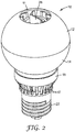
- FIG. 2 is a perspective view of light 10 as assembled. The perspective view in FIG. 2 is looking at the side and top of light 10, which is generally symmetrical from a side view.
- Light 10 includes a light guide comprised of upper and lower portions 12 and 14, an integrated thermal guide 16, a decorative light ring 18 containing a light circuit 24 having solid state light sources 25 (see FIGS. 4 and 6 ), a base portion 20, and a base 22 for electrical connection to a power source such as via conventional light sockets.
- Base 22 can be implemented with an Edison base to be secured within a corresponding light socket, and base portion 20 can be implemented with an insulator in contact with base 22.
- the light guide is shown as having two portions, it can alternatively have more than two portions or be composed of a single continuous piece of material. Also, the light guide can be configured to form an interior volume, such as by having a bulb shape as shown.
- thermal guide 16 connects with light ring 18 and base portion 20 in order to draw and dissipate heat from the solid state light sources.
- thermal guide 16 has a central core connected with external metal fins, which can conform to the shape of the light guide and be located at least partially within the interior volume formed by the light guide.
- the thermal guide can have an exterior shell conforming to the shape of the light guide along with an internal core that fits within the shell.
- Internal metal fins can be located on an inside of the exterior shell, on the internal core, or on both the shell and core.
- the exterior shell can be composed of one piece of material or multiple pieces, and the external shell houses the fins such that the fins are not visible through the light guide.
- an air passage 11 in upper portion 12 along with apertures 17 in light ring 18 allow air flow across thermal guide 16
- a power supply typically a high voltage AC power source
- FIG. 3 is an exploded perspective view illustrating components within the LED light, including first, second, and third separable connectors.
- a first separable connector includes a socket connector 30 that mates with a header connector 32 in order to provide an electrical connection between driver circuit 26 and light circuit 24.
- a second separable connector includes a poke-in connector 36 that mates with a pin connector 38. The second connector receives power from the power source via pin 38 when the light is secured within a socket and delivers the power to driver circuit 26 via poke-in connector 36.
- a third separable connector includes a neutral clip 34, which provides for an electrical ground connection between driver circuit 26 and base 22.
- the first, second, and third connectors are separable in the sense they can be connected and disconnected without damaging them or while otherwise maintaining their components substantially intact such that they can be reconnected.
- a connector can be made non-releasable when in the light while still being separable from its mating connector.
- a hard wired or soldered connection requires the connection to be broken in order to disconnect it and then resoldered in order to reconnect it. Since the electrical connectors of the present invention are separable, the light can be, for example, more easily assembled for operation or disconnected for servicing or replacement of particular components of it.
- FIGS. 4-7 illustrate details of the electrical connectors.
- FIG. 4 is a side sectional view illustrating the connectors when connected.
- FIG. 5 is a perspective view illustrating the connectors when disconnected.
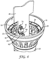
- FIG. 6 is a perspective view illustrating the first connector (socket and header connector) when connected.
- FIG. 7 is a perspective view illustrating the second connector (poke-in connector and pin) and third connector (neutral clip) when connected.
- the first connector includes socket connector 30 and header connector 32.
- Socket connector 30 includes a section 70 having a plurality of apertures 68 on its underside, a plurality of conductive strips 74, and a pin 72.
- Header connector 32 includes a section 62 having a plurality of pins 66, conductive strips 64 and a pin 60.
- socket connector is mounted to driver circuit 26 via pin 72, and conductive strips 74 are in electrical contact with conductive elements on driver circuit 26 in order to provide an electrical connection between the first connector and driver circuit 26.
- Header connector is mounted to a section 23 via pin 60. Section 23 is part of light circuit 24.
- Conductive strips 64 are in electrical contact with conductive elements on section 23 in order to provide an electrical connection between the first connector and light circuit 24, which transmits power to the LEDS.
- Pins 66 on header connector 32 mate with apertures 68 on socket connector 30 in order to establish an electrical connection between header connector 32 and socket connector 30.
- pins 66 include a set of electrically conductive pins for transmitting power and a set of non-electrically conductive (registration) pins for correctly aligning header connector 32 with socket connector 30.
- apertures 68 in socket connector 30 include a corresponding set of electrically conductive apertures and set of non-electrically conductive apertures.
- socket connector 30 and header connector 32 provide the low-voltage connection from driver circuit 26 to light circuit 24.
- driver circuit 26 is installed in the light
- socket connector 30 mates with header connector 32.
- socket 30 connector can be releasably detached from header connector 32.
- the second connector includes poke-in connector 36 that mates with a pin connector 38.
- Poke-in connector 36 is attached to driver circuit 26 and provides and electrical connection with driver circuit 26 via a conductive aperture 44.
- Pin connector 38 includes a base 40 and a pin section 42. When connected (see FIGS. 4 and 7 ), pin section 42 mates with conductive aperture 44 and established an electrical connection between base 40 and driver circuit 26.
- base 40 is in electrical contact with a power source, and transmits the power to driver circuit 26 via the connection between poke-in connector 36 and pin connector 38.
- pin connector 38 is inserted into poke-in connector 36 on the driver circuit 26.
- the third connector includes neutral clip 34 for providing a ground connection for the light.
- Neutral clip 34 includes a clip portion formed by a base 46 and tabs 48 and 50, a section 52, and a spring-like finger 54. When connected (see FIGS. 4 , and 7 ), clip portion clamps onto and is in contact with driver circuit 26 and provides an electrical connection with driver circuit 26 via tabs 48 and 50 being in contact with conductive neutral pad 56 on driver circuit 26.
- Section 52 is releasably secured to a bottom edge of insulator 20, and spring-like finger 54 fits into a slot on insulator 20 and is in electrical contact with base 22 in order to provide the ground connection between driver circuit 26 and base 22 when inserted into a socket or other fixture.
- neutral clip 34 connects to neutral pads 56 on the driver circuit 26.
- light circuit 24 is physically separable from driver circuit 26 via disconnection of socket connector 30 from header connector 32. Having the LEDs on a separate circuit from the driver circuit can provide for connection of the circuits via a separable connector and other advantages.
- the same driver circuit can be used with different light circuits such as light circuits having different colored LEDs to provide for different color lights.
- the driver circuit can be electrically connected to the light circuit in an automated assembly process.
- the slot on the thermal guide to contain the driver circuit on a circuit board can guide the circuit board contact pad and connectors into alignment with all three mating connectors so that the light assembly can be "blind mated.”
- Socket connector 30 can include a plastic material for section 70 and pin 72, apertures formed in the plastic material for the non-electrically conductive apertures, a metallic material such as copper for conductive strips 74, and a metallic material for the electrically conductive apertures connected to conductive strips 74.
- Header connector 32 can includes a plastic material for section 62 and pin 60, the non-electrically conductive pins formed from the plastic material, a metallic material such as copper for conductive strips 64, and a metallic material for the electrically conductive pins connected to conductive strips 64.
- Poke-in connector 36 can be implemented with, for example, LED poke-in product number 2008563-1 from Tyco Electronics Corporation.
- Pin connector 38 can be implemented with a unitary metal pin.
- Neutral clip 34 can be implemented with a stamped and formed metal spring clip.
- the first, second, and third connectors can alternatively be implemented with other types of materials.
- the components of the connectors can include single unitary components or a combination of sub-components combined to form the components.
- the various pins are shown as having a round shape, the pins can be square or have other types of shapes.
Landscapes
- Engineering & Computer Science (AREA)
- General Engineering & Computer Science (AREA)
- Microelectronics & Electronic Packaging (AREA)
- Physics & Mathematics (AREA)
- Optics & Photonics (AREA)
- Arrangement Of Elements, Cooling, Sealing, Or The Like Of Lighting Devices (AREA)
- Non-Portable Lighting Devices Or Systems Thereof (AREA)
- Optical Couplings Of Light Guides (AREA)
- Led Device Packages (AREA)
Abstract
a base (22) for connection to a power supply;
a light circuit (24) electrically connected with at least one light source;
a driver circuit (26) for receiving power from the power supply and providing power to drive the light source;
a light guide coupled to the light source for receiving and distributing light from the light source, wherein the light is transported through the light guide until the light is extracted from a surface of the light guide;
a thermal guide (16) integrated with the light guide for providing thermal conduction from the light source for cooling the light
a first separable connector (30,32) for providing an electrical connection between the driver circuit and the light circuit; and
a second separable connector (36,38) for providing an electrical connection between the power supply and the driver circuit.
Description
- Solid state lights, such as those using light emitting diodes (LEDs), are an alternative to incandescent light bulbs. LED lights can provide for more efficient energy use compared with incandescent light bulbs. The assembly of an LED light bulb can require hand soldering operations for various electrical connections, which is a time consuming and expensive process. Accordingly, a need exists for improved electrical connectors for LED lights and other solid state lights.
- A light, consistent with the present invention, includes integrated light and thermal guides and separable electrical connectors. The light has a base for connection to a power supply, a light circuit electrically connected with at least one solid state light source, and a driver circuit for receiving power from the power supply and providing power to drive the solid state light source. A light guide is coupled to the solid state light source for receiving and distributing light from the light source by transporting the light until it is extracted from a surface of the light guide. A thermal guide is integrated with the light guide for providing thermal conduction from the light source for cooling the light. The separable connectors include a first connector for providing an electrical connection between the driver circuit and light circuit, and a second connector for providing an electrical connection between the power supply and driver circuit. Preferred alternative and/or additional embodiments of the invention relate to the following aspects:
- 1. A light with integrated light and thermal guides and separable electrical connectors, comprising:
- a base for connection to a power supply;
- a light circuit electrically connected with at least one light source;
- a driver circuit for receiving power from the power supply and providing power to drive the light source;
- a light guide coupled to the light source for receiving and distributing light from the light source, wherein the light is transported through the light guide until the light is extracted from a surface of the light guide;
- a thermal guide integrated with the light guide for providing thermal conduction from the light source for cooling the light
- a first separable connector for providing an electrical connection between the driver circuit and the light circuit; and
- a second separable connector for providing an electrical connection between the power supply and the driver circuit.
- 2. The light of aspect 1, wherein the first connector comprises a socket connector that mates with a header connector.
- 3. The light of aspect 2, wherein the header connector comprises a first set of electrically conductive pins and a second set of non-electrically conductive pins, wherein the socket connector includes a first set of electrically conductive apertures that mate with the first set of electrically conductive pins and a second set of non-electrically conductive apertures that mate with the second set of non-electrically conductive pins.
- 4. The light of aspect 1, wherein the second connector comprises a poke-in connector that mates with a pin connector.
- 5. The light of aspect 1, further comprising a third connector for providing an electrical ground connection between the driver circuit and the base.
- 6. The light of aspect 5, wherein the third connector comprises an electrically conductive clip.
- 7. The light of aspect 1, wherein the light source comprises at least one light emitting diode.
- 8. The light of aspect 1, wherein the light circuit is physically separable from the driver circuit via disconnection of the first separable connector.
- 9. The light of aspect 1, wherein the thermal guide includes a slot for containing the driver circuit.
- 10. A light with integrated light and thermal guides and separable electrical connectors, comprising:
- a base for connection to a power supply;
- a light circuit electrically connected with at least one solid state light source;
- a driver circuit for receiving power from the power supply and providing power to drive the solid state light source;
- a light guide comprising a material having a first surface and a second surface opposite the first surface, wherein the second surface forms an interior volume, the light guide is coupled to the solid state light source for receiving and distributing light from the solid state light source through the first surface, and the light is transported through the light guide until the light is extracted from the first or second surface of the light guide;
- a thermal guide as least partially contained within the interior volume and integrated with the light guide for providing thermal conduction from the solid state light source for cooling the light;
- a first separable connector for providing an electrical connection between the driver circuit and the light circuit; and
- a second separable connector for providing an electrical connection between the power supply and the driver circuit.
- 11. The light of
aspect 10, wherein the first connector comprises a socket connector that mates with a header connector. - 12. The light of
aspect 11, wherein the header connector comprises a first set of electrically conductive pins and a second set of non-electrically conductive pins, wherein the socket connector includes a first set of electrically conductive apertures that mate with the first set of electrically conductive pins and a second set of non-electrically conductive apertures that mate with the second set of non-electrically conductive pins. - 13. The light of
aspect 10, wherein the second connector comprises a poke-in connector that mates with a pin connector. - 14. The light of
aspect 10, further comprising a third connector for providing an electrical ground connection between the driver circuit and the base. - 15. The light of
aspect 14, wherein the third connector comprises an electrically conductive clip. - 16. The light of
aspect 10, wherein the light circuit is physically separable from the driver circuit via disconnection of the first separable connector. - 17. The light of
aspect 10, wherein the light source comprises a light emitting diode. - 18. The light of
aspect 10, wherein the thermal guide comprises metal fins. - 19. The light of
aspect 10, wherein the light guide comprises a bulb shape. - 20. The light of
aspect 10, wherein the thermal guide includes a slot for containing the driver circuit. - The accompanying drawings are incorporated in and constitute a part of this specification and, together with the description, explain the advantages and principles of the invention. In the drawings,
-
FIG. 1 is an exploded perspective view of an LED light with a light guide and thermal guide; -
FIG. 2 is a perspective view of the light ofFIG. 1 as assembled; -
FIG. 3 is an exploded perspective view illustrating components within the LED light including three electrical connectors; -
FIG. 4 is a side sectional view of components within the LED light including the electrical connectors when connected; -
FIG. 5 is an exploded perspective view illustrating the electrical connectors when disconnected; -
FIG. 6 is a perspective view illustrating the first electrical connector when connected; and -
FIG. 7 is a perspective view illustrating the second and third electrical connectors when connected. - This connector scheme provides electrical connections from the driver circuit of a light to power a circuit with LEDs or other solid state light sources on it. The scheme also provides connections from the driver circuit to the base of the light for the high-voltage side connection. In both of these cases, the design allows for the electrical connections to be made without the use of hand-soldered wires, for example.
-
FIG. 1 is an exploded perspective view of asolid state light 10.FIG. 2 is a perspective view of light 10 as assembled. The perspective view inFIG. 2 is looking at the side and top oflight 10, which is generally symmetrical from a side view.Light 10 includes a light guide comprised of upper andlower portions thermal guide 16, a decorativelight ring 18 containing alight circuit 24 having solid state light sources 25 (seeFIGS. 4 and6 ), abase portion 20, and abase 22 for electrical connection to a power source such as via conventional light sockets.Base 22 can be implemented with an Edison base to be secured within a corresponding light socket, andbase portion 20 can be implemented with an insulator in contact withbase 22. Although the light guide is shown as having two portions, it can alternatively have more than two portions or be composed of a single continuous piece of material. Also, the light guide can be configured to form an interior volume, such as by having a bulb shape as shown. - As illustrated in
FIG. 2 ,upper portion 12 mates withlower portion 14 to form the light guide, andlower portion 14 mounts tolight ring 18 in order to optically couple with solid state light sources onlight circuit 24.Thermal guide 16 connects withlight ring 18 andbase portion 20 in order to draw and dissipate heat from the solid state light sources. As shown inFIG. 1 ,thermal guide 16 has a central core connected with external metal fins, which can conform to the shape of the light guide and be located at least partially within the interior volume formed by the light guide. Alternatively as illustrated inFIG. 4 , the thermal guide can have an exterior shell conforming to the shape of the light guide along with an internal core that fits within the shell. Internal metal fins can be located on an inside of the exterior shell, on the internal core, or on both the shell and core. The exterior shell can be composed of one piece of material or multiple pieces, and the external shell houses the fins such that the fins are not visible through the light guide. As shown inFIGS. 1 and2 , anair passage 11 inupper portion 12 along withapertures 17 inlight ring 18 allow air flow acrossthermal guide 16 - A
driver circuit 26, on a printed circuit board or flexible circuit, is mounted in the central core ofthermal guide 16 such as within a slot in the thermal guide (seeFIG. 4 ). When mounted,driver circuit 26 is electrically connected with solid state light sources onlight circuit 24 andbase 22.Driver circuit 26 receives power from a power supply, typically a high voltage AC power source, viabase 22 and provides the required voltages and currents to drive the solid state light sources.Driver circuit 26 can be thermally coupled to the thermal guide in order to help cool the electronic components. - Examples of solid state lights, including lights using LEDs, are described in
U.S. Patent Application Publication No. 2011/0032708 andU.S. Patent Application Serial No. 12/960642, entitled "Solid State Light with Light guide and Integrated Thermal Guide," and filed December 6, 2010 -
FIG. 3 is an exploded perspective view illustrating components within the LED light, including first, second, and third separable connectors. A first separable connector includes asocket connector 30 that mates with aheader connector 32 in order to provide an electrical connection betweendriver circuit 26 andlight circuit 24. A second separable connector includes a poke-inconnector 36 that mates with apin connector 38. The second connector receives power from the power source viapin 38 when the light is secured within a socket and delivers the power todriver circuit 26 via poke-inconnector 36. A third separable connector includes aneutral clip 34, which provides for an electrical ground connection betweendriver circuit 26 andbase 22. - The first, second, and third connectors are separable in the sense they can be connected and disconnected without damaging them or while otherwise maintaining their components substantially intact such that they can be reconnected. In some cases, a connector can be made non-releasable when in the light while still being separable from its mating connector. In comparison, a hard wired or soldered connection requires the connection to be broken in order to disconnect it and then resoldered in order to reconnect it. Since the electrical connectors of the present invention are separable, the light can be, for example, more easily assembled for operation or disconnected for servicing or replacement of particular components of it.
-
FIGS. 4-7 illustrate details of the electrical connectors.FIG. 4 is a side sectional view illustrating the connectors when connected.FIG. 5 is a perspective view illustrating the connectors when disconnected.FIG. 6 is a perspective view illustrating the first connector (socket and header connector) when connected.FIG. 7 is a perspective view illustrating the second connector (poke-in connector and pin) and third connector (neutral clip) when connected. - As shown in
FIGS. 4-6 , the first connector includessocket connector 30 andheader connector 32.Socket connector 30 includes asection 70 having a plurality ofapertures 68 on its underside, a plurality ofconductive strips 74, and apin 72.Header connector 32 includes asection 62 having a plurality ofpins 66,conductive strips 64 and apin 60. When connected (seeFIGS. 4 and6 ), socket connector is mounted todriver circuit 26 viapin 72, andconductive strips 74 are in electrical contact with conductive elements ondriver circuit 26 in order to provide an electrical connection between the first connector anddriver circuit 26. Header connector is mounted to asection 23 viapin 60.Section 23 is part oflight circuit 24.Conductive strips 64 are in electrical contact with conductive elements onsection 23 in order to provide an electrical connection between the first connector andlight circuit 24, which transmits power to the LEDS.Pins 66 onheader connector 32 mate withapertures 68 onsocket connector 30 in order to establish an electrical connection betweenheader connector 32 andsocket connector 30. In this embodiment, pins 66 include a set of electrically conductive pins for transmitting power and a set of non-electrically conductive (registration) pins for correctly aligningheader connector 32 withsocket connector 30. Likewise,apertures 68 insocket connector 30 include a corresponding set of electrically conductive apertures and set of non-electrically conductive apertures. - When connected,
socket connector 30 andheader connector 32 provide the low-voltage connection fromdriver circuit 26 tolight circuit 24. Whendriver circuit 26 is installed in the light,socket connector 30 mates withheader connector 32. Conversely, ifdriver circuit 26 is removed from the light,socket 30 connector can be releasably detached fromheader connector 32. - As shown in
FIGS. 4 ,5 , and7 , the second connector includes poke-inconnector 36 that mates with apin connector 38. Poke-inconnector 36 is attached todriver circuit 26 and provides and electrical connection withdriver circuit 26 via aconductive aperture 44.Pin connector 38 includes abase 40 and apin section 42. When connected (seeFIGS. 4 and7 ),pin section 42 mates withconductive aperture 44 and established an electrical connection betweenbase 40 anddriver circuit 26. When the light is installed within a light socket or other fixture,base 40 is in electrical contact with a power source, and transmits the power todriver circuit 26 via the connection between poke-inconnector 36 andpin connector 38. During assembly of the light,pin connector 38 is inserted into poke-inconnector 36 on thedriver circuit 26. - As shown in
FIGS. 4 ,5 , and7 , the third connector includesneutral clip 34 for providing a ground connection for the light.Neutral clip 34 includes a clip portion formed by abase 46 andtabs section 52, and a spring-like finger 54. When connected (seeFIGS. 4 , and7 ), clip portion clamps onto and is in contact withdriver circuit 26 and provides an electrical connection withdriver circuit 26 viatabs neutral pad 56 ondriver circuit 26.Section 52 is releasably secured to a bottom edge ofinsulator 20, and spring-like finger 54 fits into a slot oninsulator 20 and is in electrical contact withbase 22 in order to provide the ground connection betweendriver circuit 26 andbase 22 when inserted into a socket or other fixture. During assembly, whendriver circuit 26 is inserted intobase 22,neutral clip 34 connects toneutral pads 56 on thedriver circuit 26. - In this embodiment,
light circuit 24 is physically separable fromdriver circuit 26 via disconnection ofsocket connector 30 fromheader connector 32. Having the LEDs on a separate circuit from the driver circuit can provide for connection of the circuits via a separable connector and other advantages. The same driver circuit can be used with different light circuits such as light circuits having different colored LEDs to provide for different color lights. The driver circuit can be electrically connected to the light circuit in an automated assembly process. Furthermore as illustrated inFIG. 4 , the slot on the thermal guide to contain the driver circuit on a circuit board can guide the circuit board contact pad and connectors into alignment with all three mating connectors so that the light assembly can be "blind mated." - The following are exemplary components and materials for the first, second, and third connectors.
Socket connector 30 can include a plastic material forsection 70 andpin 72, apertures formed in the plastic material for the non-electrically conductive apertures, a metallic material such as copper forconductive strips 74, and a metallic material for the electrically conductive apertures connected toconductive strips 74.Header connector 32 can includes a plastic material forsection 62 andpin 60, the non-electrically conductive pins formed from the plastic material, a metallic material such as copper forconductive strips 64, and a metallic material for the electrically conductive pins connected toconductive strips 64. Poke-inconnector 36 can be implemented with, for example, LED poke-in product number 2008563-1 from Tyco Electronics Corporation.Pin connector 38 can be implemented with a unitary metal pin.Neutral clip 34 can be implemented with a stamped and formed metal spring clip. - The first, second, and third connectors can alternatively be implemented with other types of materials. The components of the connectors can include single unitary components or a combination of sub-components combined to form the components. Although the various pins are shown as having a round shape, the pins can be square or have other types of shapes.
Claims (9)
- A light with integrated light and thermal guides and separable electrical connectors, comprising:a base for connection to a power supply;a light circuit electrically connected with at least one light source;a driver circuit for receiving power from the power supply and providing power to drive the light source;a light guide coupled to the light source for receiving and distributing light from the light source, wherein the light is transported through the light guide until the light is extracted from a surface of the light guide;a thermal guide integrated with the light guide for providing thermal conduction from the light source for cooling the lighta first separable connector for providing an electrical connection between the driver circuit and the light circuit; anda second separable connector for providing an electrical connection between the power supply and the driver circuit.
- The light of claim 1, wherein the first connector comprises a socket connector that mates with a header connector.
- The light of claim 2, wherein the header connector comprises a first set of electrically conductive pins and a second set of non-electrically conductive pins, wherein the socket connector includes a first set of electrically conductive apertures that mate with the first set of electrically conductive pins and a second set of non-electrically conductive apertures that mate with the second set of non-electrically conductive pins.
- The light of claim 1, wherein the second connector comprises a poke-in connector that mates with a pin connector.
- The light of claim 1, further comprising a third connector for providing an electrical ground connection between the driver circuit and the base.
- The light of claim 5, wherein the third connector comprises an electrically conductive clip.
- The light of claim 1, wherein the light source comprises at least one light emitting diode.
- The light of claim 1, wherein the light circuit is physically separable from the driver circuit via disconnection of the first separable connector.
- The light of claim 1, wherein the thermal guide includes a slot for containing the driver circuit.
Applications Claiming Priority (3)
| Application Number | Priority Date | Filing Date | Title |
|---|---|---|---|
| US13/435,224 US9175813B2 (en) | 2012-03-30 | 2012-03-30 | Electrical connectors for solid state light |
| PCT/US2013/031244 WO2013148239A1 (en) | 2012-03-30 | 2013-03-14 | Electrical connectors for solid state light |
| EP13769434.5A EP2831498B1 (en) | 2012-03-30 | 2013-03-14 | Electrical connectors for solid state light |
Related Parent Applications (1)
| Application Number | Title | Priority Date | Filing Date |
|---|---|---|---|
| EP13769434.5A Division EP2831498B1 (en) | 2012-03-30 | 2013-03-14 | Electrical connectors for solid state light |
Publications (2)
| Publication Number | Publication Date |
|---|---|
| EP3252373A1 true EP3252373A1 (en) | 2017-12-06 |
| EP3252373B1 EP3252373B1 (en) | 2019-01-02 |
Family
ID=49233982
Family Applications (2)
| Application Number | Title | Priority Date | Filing Date |
|---|---|---|---|
| EP13769434.5A Not-in-force EP2831498B1 (en) | 2012-03-30 | 2013-03-14 | Electrical connectors for solid state light |
| EP17173207.6A Not-in-force EP3252373B1 (en) | 2012-03-30 | 2013-03-14 | Electrical connectors for solid state light |
Family Applications Before (1)
| Application Number | Title | Priority Date | Filing Date |
|---|---|---|---|
| EP13769434.5A Not-in-force EP2831498B1 (en) | 2012-03-30 | 2013-03-14 | Electrical connectors for solid state light |
Country Status (7)
| Country | Link |
|---|---|
| US (1) | US9175813B2 (en) |
| EP (2) | EP2831498B1 (en) |
| JP (1) | JP2015512557A (en) |
| KR (1) | KR102015687B1 (en) |
| CN (1) | CN104204663B (en) |
| TW (1) | TW201346172A (en) |
| WO (1) | WO2013148239A1 (en) |
Families Citing this family (24)
| Publication number | Priority date | Publication date | Assignee | Title |
|---|---|---|---|---|
| CN102913773B (en) * | 2011-08-02 | 2016-05-04 | 欧司朗股份有限公司 | LED luminescence component and there is the LED remodeling lamp of this LED luminescence component |
| US8926131B2 (en) * | 2012-05-08 | 2015-01-06 | 3M Innovative Properties Company | Solid state light with aligned light guide and integrated vented thermal guide |
| CN105190169B (en) * | 2013-05-08 | 2019-01-04 | 飞利浦照明控股有限公司 | Lighting apparatus |
| US9151480B2 (en) | 2013-08-30 | 2015-10-06 | Tyco Electronics Corporation | Light bulb assembly |
| US9310061B2 (en) * | 2013-08-30 | 2016-04-12 | Tyco Electronics Corporation | Light bulb assembly |
| US9267674B2 (en) * | 2013-10-18 | 2016-02-23 | 3M Innovative Properties Company | Solid state light with enclosed light guide and integrated thermal guide |
| CN203892919U (en) * | 2014-03-26 | 2014-10-22 | 飞利浦(中国)投资有限公司 | Light device, LED light and light fixture |
| TWI522566B (en) * | 2014-03-31 | 2016-02-21 | 瑞儀光電股份有限公司 | Ventilated lamps |
| EP3134674B1 (en) | 2014-04-21 | 2018-06-13 | Philips Lighting Holding B.V. | Lighting device and luminaire |
| US9951910B2 (en) * | 2014-05-19 | 2018-04-24 | Cree, Inc. | LED lamp with base having a biased electrical interconnect |
| CN104154443A (en) * | 2014-08-01 | 2014-11-19 | 乐清市健坤接插件有限公司 | Soldering-free LED (light emitting diode) bulb lamp |
| US9279548B1 (en) | 2014-08-18 | 2016-03-08 | 3M Innovative Properties Company | Light collimating assembly with dual horns |
| CN107191805A (en) * | 2014-09-02 | 2017-09-22 | 曹华诚 | LED lamp head structure |
| US9829187B2 (en) | 2014-10-09 | 2017-11-28 | Elumigen Llc | Spring lock clip for coupling a circuit board to an electrical base |
| DE102014225486A1 (en) * | 2014-12-10 | 2016-06-16 | Osram Gmbh | Lamp with driver board and socket |
| CN105180054A (en) * | 2015-08-28 | 2015-12-23 | 陈初英 | LED automobile lamp capable of being rapidly plugged and assembled |
| KR102439547B1 (en) * | 2015-11-05 | 2022-09-02 | 엘지이노텍 주식회사 | Lamp unit and vehicle lamp including same |
| US9976705B2 (en) * | 2016-05-26 | 2018-05-22 | Elumigen, Llc | Light engine for AC and DC driver architectures for LED lamps |
| US10871282B2 (en) * | 2016-06-23 | 2020-12-22 | Oppie Lighting Co., Ltd. | Illuminator device |
| CN206918825U (en) * | 2017-04-25 | 2018-01-23 | 漳州立达信光电子科技有限公司 | A split downlight |
| US10788166B2 (en) * | 2017-05-05 | 2020-09-29 | Gmy Lighting Technology Co., Ltd. | Type of LED lamp structure and its preparation process |
| CN109838711A (en) * | 2017-11-24 | 2019-06-04 | 通用电气照明解决方案有限公司 | A kind of lamp |
| CN209929501U (en) * | 2019-05-23 | 2020-01-10 | 漳州立达信光电子科技有限公司 | Drive input terminal structure and lamp |
| CN215174775U (en) * | 2021-03-29 | 2021-12-14 | 欧司朗股份有限公司 | Lamp with a light source |
Citations (8)
| Publication number | Priority date | Publication date | Assignee | Title |
|---|---|---|---|---|
| CN1880844A (en) * | 2005-04-08 | 2006-12-20 | 东芝照明技术株式会社 | lamp |
| US20090189528A1 (en) * | 2008-01-25 | 2009-07-30 | Foxsemicon Integrated Technology, Inc. | Illuminating device |
| US20090218923A1 (en) * | 2008-02-28 | 2009-09-03 | Tyco Electronics Corporation | Integrated led driver for led socket |
| US20110028015A1 (en) * | 2009-07-30 | 2011-02-03 | Tyco Electronics Corporation | Quick insertion lamp assembly |
| US20110032708A1 (en) | 2009-08-04 | 2011-02-10 | 3M Innovative Properties Company | Solid state light with optical guide and integrated thermal guide |
| US20110101861A1 (en) * | 2009-10-30 | 2011-05-05 | Young Ho Yoo | Led lamp |
| US20110234076A1 (en) * | 2010-03-26 | 2011-09-29 | Altair Engineering, Inc. | Inside-out led bulb |
| US20110309735A1 (en) * | 2010-06-18 | 2011-12-22 | Parker Jeffery R | Light bulb using solid-state light sources |
Family Cites Families (13)
| Publication number | Priority date | Publication date | Assignee | Title |
|---|---|---|---|---|
| US6773154B2 (en) | 2002-08-21 | 2004-08-10 | North American Lighting, Inc. | Automotive lighting device |
| US7708452B2 (en) | 2006-06-08 | 2010-05-04 | Lighting Science Group Corporation | Lighting apparatus including flexible power supply |
| US20110128742A9 (en) | 2007-01-07 | 2011-06-02 | Pui Hang Yuen | High efficiency low cost safety light emitting diode illumination device |
| KR20100110045A (en) * | 2009-04-02 | 2010-10-12 | 화우테크놀러지 주식회사 | Led lamp with uniform light diffusion |
| US8342733B2 (en) * | 2009-12-14 | 2013-01-01 | Tyco Electronics Corporation | LED lighting assemblies |
| KR101045457B1 (en) | 2010-02-12 | 2011-07-01 | 희성전자 주식회사 | Light Emitting Diode Lamp with Converter |
| JP2012009390A (en) | 2010-06-28 | 2012-01-12 | Toshiba Lighting & Technology Corp | Light-emitting device, and lighting fixture |
| CN101922633A (en) * | 2010-07-22 | 2010-12-22 | 鸿富锦精密工业(深圳)有限公司 | LED lighting |
| US8282249B2 (en) | 2010-08-20 | 2012-10-09 | Siltek Electronic (Guangzhou) Co., Ltd. | Luminaire |
| KR101035951B1 (en) | 2010-09-28 | 2011-05-23 | (주)지피에이 | LED lamp connector |
| USD642704S1 (en) | 2010-12-06 | 2011-08-02 | 3M Innovative Properties Company | Solid state light assembly |
| US8487518B2 (en) | 2010-12-06 | 2013-07-16 | 3M Innovative Properties Company | Solid state light with optical guide and integrated thermal guide |
| CN103649636A (en) * | 2011-03-23 | 2014-03-19 | 长寿灯泡有限责任公司 | Heat transfer assembly for LED-based light bulb or lamp device |
-
2012
- 2012-03-30 US US13/435,224 patent/US9175813B2/en not_active Expired - Fee Related
-
2013
- 2013-03-14 KR KR1020147030071A patent/KR102015687B1/en not_active Expired - Fee Related
- 2013-03-14 CN CN201380017084.3A patent/CN104204663B/en not_active Expired - Fee Related
- 2013-03-14 EP EP13769434.5A patent/EP2831498B1/en not_active Not-in-force
- 2013-03-14 JP JP2015503292A patent/JP2015512557A/en active Pending
- 2013-03-14 EP EP17173207.6A patent/EP3252373B1/en not_active Not-in-force
- 2013-03-14 WO PCT/US2013/031244 patent/WO2013148239A1/en not_active Ceased
- 2013-03-28 TW TW102111049A patent/TW201346172A/en unknown
Patent Citations (8)
| Publication number | Priority date | Publication date | Assignee | Title |
|---|---|---|---|---|
| CN1880844A (en) * | 2005-04-08 | 2006-12-20 | 东芝照明技术株式会社 | lamp |
| US20090189528A1 (en) * | 2008-01-25 | 2009-07-30 | Foxsemicon Integrated Technology, Inc. | Illuminating device |
| US20090218923A1 (en) * | 2008-02-28 | 2009-09-03 | Tyco Electronics Corporation | Integrated led driver for led socket |
| US20110028015A1 (en) * | 2009-07-30 | 2011-02-03 | Tyco Electronics Corporation | Quick insertion lamp assembly |
| US20110032708A1 (en) | 2009-08-04 | 2011-02-10 | 3M Innovative Properties Company | Solid state light with optical guide and integrated thermal guide |
| US20110101861A1 (en) * | 2009-10-30 | 2011-05-05 | Young Ho Yoo | Led lamp |
| US20110234076A1 (en) * | 2010-03-26 | 2011-09-29 | Altair Engineering, Inc. | Inside-out led bulb |
| US20110309735A1 (en) * | 2010-06-18 | 2011-12-22 | Parker Jeffery R | Light bulb using solid-state light sources |
Also Published As
| Publication number | Publication date |
|---|---|
| WO2013148239A1 (en) | 2013-10-03 |
| EP2831498A4 (en) | 2016-01-13 |
| EP3252373B1 (en) | 2019-01-02 |
| EP2831498B1 (en) | 2017-05-31 |
| CN104204663B (en) | 2017-06-13 |
| KR20150002701A (en) | 2015-01-07 |
| EP2831498A1 (en) | 2015-02-04 |
| KR102015687B1 (en) | 2019-08-28 |
| CN104204663A (en) | 2014-12-10 |
| US20130257278A1 (en) | 2013-10-03 |
| TW201346172A (en) | 2013-11-16 |
| US9175813B2 (en) | 2015-11-03 |
| JP2015512557A (en) | 2015-04-27 |
Similar Documents
| Publication | Publication Date | Title |
|---|---|---|
| US9175813B2 (en) | Electrical connectors for solid state light | |
| EP2257730B1 (en) | Integrated led driver for led socket | |
| JP5669188B2 (en) | LED lighting assembly | |
| US8684572B2 (en) | LED connector assembly | |
| KR101690332B1 (en) | Led socket assembly | |
| US8814383B2 (en) | Lighting module | |
| CN103946622B (en) | LED lights | |
| JP6010116B2 (en) | Socket, lighting module, and lighting fixture | |
| CN104081118B (en) | LED lamp assembly | |
| US10253929B2 (en) | Lamp comprising a driver circuit board and a base | |
| KR101378697B1 (en) | Led socket assembly | |
| CN106523942A (en) | Heatsink with integrated electrical and base contacts | |
| CN216624776U (en) | Indicator light module and electrical appliance | |
| TW201604481A (en) | Light-emitting diode light bulb | |
| GB2499782A (en) | LED lamp having shell structure | |
| GB2499783A (en) | LED lamp having shell structure | |
| CN105318214A (en) | Light Emitting Diode Bulbs |
Legal Events
| Date | Code | Title | Description |
|---|---|---|---|
| PUAI | Public reference made under article 153(3) epc to a published international application that has entered the european phase |
Free format text: ORIGINAL CODE: 0009012 |
|
| STAA | Information on the status of an ep patent application or granted ep patent |
Free format text: STATUS: THE APPLICATION HAS BEEN PUBLISHED |
|
| AC | Divisional application: reference to earlier application |
Ref document number: 2831498 Country of ref document: EP Kind code of ref document: P |
|
| AK | Designated contracting states |
Kind code of ref document: A1 Designated state(s): AL AT BE BG CH CY CZ DE DK EE ES FI FR GB GR HR HU IE IS IT LI LT LU LV MC MK MT NL NO PL PT RO RS SE SI SK SM TR |
|
| STAA | Information on the status of an ep patent application or granted ep patent |
Free format text: STATUS: REQUEST FOR EXAMINATION WAS MADE |
|
| GRAP | Despatch of communication of intention to grant a patent |
Free format text: ORIGINAL CODE: EPIDOSNIGR1 |
|
| STAA | Information on the status of an ep patent application or granted ep patent |
Free format text: STATUS: GRANT OF PATENT IS INTENDED |
|
| 17P | Request for examination filed |
Effective date: 20180530 |
|
| RBV | Designated contracting states (corrected) |
Designated state(s): AL AT BE BG CH CY CZ DE DK EE ES FI FR GB GR HR HU IE IS IT LI LT LU LV MC MK MT NL NO PL PT RO RS SE SI SK SM TR |
|
| RIC1 | Information provided on ipc code assigned before grant |
Ipc: F21V 17/00 20060101ALI20180620BHEP Ipc: F21Y 115/10 20160101ALN20180620BHEP Ipc: F21V 29/00 20150101AFI20180620BHEP Ipc: H01R 12/51 20110101ALI20180620BHEP Ipc: F21S 2/00 20160101ALI20180620BHEP |
|
| INTG | Intention to grant announced |
Effective date: 20180710 |
|
| GRAS | Grant fee paid |
Free format text: ORIGINAL CODE: EPIDOSNIGR3 |
|
| GRAA | (expected) grant |
Free format text: ORIGINAL CODE: 0009210 |
|
| STAA | Information on the status of an ep patent application or granted ep patent |
Free format text: STATUS: THE PATENT HAS BEEN GRANTED |
|
| AC | Divisional application: reference to earlier application |
Ref document number: 2831498 Country of ref document: EP Kind code of ref document: P |
|
| AK | Designated contracting states |
Kind code of ref document: B1 Designated state(s): AL AT BE BG CH CY CZ DE DK EE ES FI FR GB GR HR HU IE IS IT LI LT LU LV MC MK MT NL NO PL PT RO RS SE SI SK SM TR |
|
| REG | Reference to a national code |
Ref country code: GB Ref legal event code: FG4D |
|
| REG | Reference to a national code |
Ref country code: CH Ref legal event code: EP Ref country code: AT Ref legal event code: REF Ref document number: 1084852 Country of ref document: AT Kind code of ref document: T Effective date: 20190115 |
|
| REG | Reference to a national code |
Ref country code: IE Ref legal event code: FG4D |
|
| REG | Reference to a national code |
Ref country code: DE Ref legal event code: R096 Ref document number: 602013049433 Country of ref document: DE |
|
| PGFP | Annual fee paid to national office [announced via postgrant information from national office to epo] |
Ref country code: DE Payment date: 20190226 Year of fee payment: 7 |
|
| REG | Reference to a national code |
Ref country code: NL Ref legal event code: MP Effective date: 20190102 |
|
| REG | Reference to a national code |
Ref country code: LT Ref legal event code: MG4D |
|
| REG | Reference to a national code |
Ref country code: AT Ref legal event code: MK05 Ref document number: 1084852 Country of ref document: AT Kind code of ref document: T Effective date: 20190102 |
|
| PG25 | Lapsed in a contracting state [announced via postgrant information from national office to epo] |
Ref country code: NL Free format text: LAPSE BECAUSE OF FAILURE TO SUBMIT A TRANSLATION OF THE DESCRIPTION OR TO PAY THE FEE WITHIN THE PRESCRIBED TIME-LIMIT Effective date: 20190102 |
|
| PG25 | Lapsed in a contracting state [announced via postgrant information from national office to epo] |
Ref country code: LT Free format text: LAPSE BECAUSE OF FAILURE TO SUBMIT A TRANSLATION OF THE DESCRIPTION OR TO PAY THE FEE WITHIN THE PRESCRIBED TIME-LIMIT Effective date: 20190102 Ref country code: NO Free format text: LAPSE BECAUSE OF FAILURE TO SUBMIT A TRANSLATION OF THE DESCRIPTION OR TO PAY THE FEE WITHIN THE PRESCRIBED TIME-LIMIT Effective date: 20190402 Ref country code: FI Free format text: LAPSE BECAUSE OF FAILURE TO SUBMIT A TRANSLATION OF THE DESCRIPTION OR TO PAY THE FEE WITHIN THE PRESCRIBED TIME-LIMIT Effective date: 20190102 Ref country code: ES Free format text: LAPSE BECAUSE OF FAILURE TO SUBMIT A TRANSLATION OF THE DESCRIPTION OR TO PAY THE FEE WITHIN THE PRESCRIBED TIME-LIMIT Effective date: 20190102 Ref country code: PT Free format text: LAPSE BECAUSE OF FAILURE TO SUBMIT A TRANSLATION OF THE DESCRIPTION OR TO PAY THE FEE WITHIN THE PRESCRIBED TIME-LIMIT Effective date: 20190502 Ref country code: SE Free format text: LAPSE BECAUSE OF FAILURE TO SUBMIT A TRANSLATION OF THE DESCRIPTION OR TO PAY THE FEE WITHIN THE PRESCRIBED TIME-LIMIT Effective date: 20190102 Ref country code: PL Free format text: LAPSE BECAUSE OF FAILURE TO SUBMIT A TRANSLATION OF THE DESCRIPTION OR TO PAY THE FEE WITHIN THE PRESCRIBED TIME-LIMIT Effective date: 20190102 |
|
| PG25 | Lapsed in a contracting state [announced via postgrant information from national office to epo] |
Ref country code: LV Free format text: LAPSE BECAUSE OF FAILURE TO SUBMIT A TRANSLATION OF THE DESCRIPTION OR TO PAY THE FEE WITHIN THE PRESCRIBED TIME-LIMIT Effective date: 20190102 Ref country code: IS Free format text: LAPSE BECAUSE OF FAILURE TO SUBMIT A TRANSLATION OF THE DESCRIPTION OR TO PAY THE FEE WITHIN THE PRESCRIBED TIME-LIMIT Effective date: 20190502 Ref country code: HR Free format text: LAPSE BECAUSE OF FAILURE TO SUBMIT A TRANSLATION OF THE DESCRIPTION OR TO PAY THE FEE WITHIN THE PRESCRIBED TIME-LIMIT Effective date: 20190102 Ref country code: GR Free format text: LAPSE BECAUSE OF FAILURE TO SUBMIT A TRANSLATION OF THE DESCRIPTION OR TO PAY THE FEE WITHIN THE PRESCRIBED TIME-LIMIT Effective date: 20190403 Ref country code: BG Free format text: LAPSE BECAUSE OF FAILURE TO SUBMIT A TRANSLATION OF THE DESCRIPTION OR TO PAY THE FEE WITHIN THE PRESCRIBED TIME-LIMIT Effective date: 20190402 Ref country code: RS Free format text: LAPSE BECAUSE OF FAILURE TO SUBMIT A TRANSLATION OF THE DESCRIPTION OR TO PAY THE FEE WITHIN THE PRESCRIBED TIME-LIMIT Effective date: 20190102 |
|
| REG | Reference to a national code |
Ref country code: DE Ref legal event code: R097 Ref document number: 602013049433 Country of ref document: DE |
|
| PG25 | Lapsed in a contracting state [announced via postgrant information from national office to epo] |
Ref country code: MC Free format text: LAPSE BECAUSE OF FAILURE TO SUBMIT A TRANSLATION OF THE DESCRIPTION OR TO PAY THE FEE WITHIN THE PRESCRIBED TIME-LIMIT Effective date: 20190102 Ref country code: DK Free format text: LAPSE BECAUSE OF FAILURE TO SUBMIT A TRANSLATION OF THE DESCRIPTION OR TO PAY THE FEE WITHIN THE PRESCRIBED TIME-LIMIT Effective date: 20190102 Ref country code: AT Free format text: LAPSE BECAUSE OF FAILURE TO SUBMIT A TRANSLATION OF THE DESCRIPTION OR TO PAY THE FEE WITHIN THE PRESCRIBED TIME-LIMIT Effective date: 20190102 Ref country code: EE Free format text: LAPSE BECAUSE OF FAILURE TO SUBMIT A TRANSLATION OF THE DESCRIPTION OR TO PAY THE FEE WITHIN THE PRESCRIBED TIME-LIMIT Effective date: 20190102 Ref country code: RO Free format text: LAPSE BECAUSE OF FAILURE TO SUBMIT A TRANSLATION OF THE DESCRIPTION OR TO PAY THE FEE WITHIN THE PRESCRIBED TIME-LIMIT Effective date: 20190102 Ref country code: CZ Free format text: LAPSE BECAUSE OF FAILURE TO SUBMIT A TRANSLATION OF THE DESCRIPTION OR TO PAY THE FEE WITHIN THE PRESCRIBED TIME-LIMIT Effective date: 20190102 Ref country code: SK Free format text: LAPSE BECAUSE OF FAILURE TO SUBMIT A TRANSLATION OF THE DESCRIPTION OR TO PAY THE FEE WITHIN THE PRESCRIBED TIME-LIMIT Effective date: 20190102 Ref country code: IT Free format text: LAPSE BECAUSE OF FAILURE TO SUBMIT A TRANSLATION OF THE DESCRIPTION OR TO PAY THE FEE WITHIN THE PRESCRIBED TIME-LIMIT Effective date: 20190102 Ref country code: AL Free format text: LAPSE BECAUSE OF FAILURE TO SUBMIT A TRANSLATION OF THE DESCRIPTION OR TO PAY THE FEE WITHIN THE PRESCRIBED TIME-LIMIT Effective date: 20190102 |
|
| REG | Reference to a national code |
Ref country code: CH Ref legal event code: PL |
|
| PLBE | No opposition filed within time limit |
Free format text: ORIGINAL CODE: 0009261 |
|
| STAA | Information on the status of an ep patent application or granted ep patent |
Free format text: STATUS: NO OPPOSITION FILED WITHIN TIME LIMIT |
|
| PG25 | Lapsed in a contracting state [announced via postgrant information from national office to epo] |
Ref country code: SM Free format text: LAPSE BECAUSE OF FAILURE TO SUBMIT A TRANSLATION OF THE DESCRIPTION OR TO PAY THE FEE WITHIN THE PRESCRIBED TIME-LIMIT Effective date: 20190102 Ref country code: LU Free format text: LAPSE BECAUSE OF NON-PAYMENT OF DUE FEES Effective date: 20190314 |
|
| REG | Reference to a national code |
Ref country code: BE Ref legal event code: MM Effective date: 20190331 |
|
| 26N | No opposition filed |
Effective date: 20191003 |
|
| GBPC | Gb: european patent ceased through non-payment of renewal fee |
Effective date: 20190402 |
|
| PG25 | Lapsed in a contracting state [announced via postgrant information from national office to epo] |
Ref country code: CH Free format text: LAPSE BECAUSE OF NON-PAYMENT OF DUE FEES Effective date: 20190331 Ref country code: LI Free format text: LAPSE BECAUSE OF NON-PAYMENT OF DUE FEES Effective date: 20190331 Ref country code: GB Free format text: LAPSE BECAUSE OF NON-PAYMENT OF DUE FEES Effective date: 20190402 Ref country code: IE Free format text: LAPSE BECAUSE OF NON-PAYMENT OF DUE FEES Effective date: 20190314 |
|
| PG25 | Lapsed in a contracting state [announced via postgrant information from national office to epo] |
Ref country code: FR Free format text: LAPSE BECAUSE OF NON-PAYMENT OF DUE FEES Effective date: 20190331 Ref country code: BE Free format text: LAPSE BECAUSE OF NON-PAYMENT OF DUE FEES Effective date: 20190331 Ref country code: SI Free format text: LAPSE BECAUSE OF FAILURE TO SUBMIT A TRANSLATION OF THE DESCRIPTION OR TO PAY THE FEE WITHIN THE PRESCRIBED TIME-LIMIT Effective date: 20190102 |
|
| PG25 | Lapsed in a contracting state [announced via postgrant information from national office to epo] |
Ref country code: TR Free format text: LAPSE BECAUSE OF FAILURE TO SUBMIT A TRANSLATION OF THE DESCRIPTION OR TO PAY THE FEE WITHIN THE PRESCRIBED TIME-LIMIT Effective date: 20190102 |
|
| PG25 | Lapsed in a contracting state [announced via postgrant information from national office to epo] |
Ref country code: MT Free format text: LAPSE BECAUSE OF NON-PAYMENT OF DUE FEES Effective date: 20190314 |
|
| REG | Reference to a national code |
Ref country code: DE Ref legal event code: R119 Ref document number: 602013049433 Country of ref document: DE |
|
| PG25 | Lapsed in a contracting state [announced via postgrant information from national office to epo] |
Ref country code: DE Free format text: LAPSE BECAUSE OF NON-PAYMENT OF DUE FEES Effective date: 20201001 |
|
| PG25 | Lapsed in a contracting state [announced via postgrant information from national office to epo] |
Ref country code: CY Free format text: LAPSE BECAUSE OF FAILURE TO SUBMIT A TRANSLATION OF THE DESCRIPTION OR TO PAY THE FEE WITHIN THE PRESCRIBED TIME-LIMIT Effective date: 20190102 |
|
| PG25 | Lapsed in a contracting state [announced via postgrant information from national office to epo] |
Ref country code: HU Free format text: LAPSE BECAUSE OF FAILURE TO SUBMIT A TRANSLATION OF THE DESCRIPTION OR TO PAY THE FEE WITHIN THE PRESCRIBED TIME-LIMIT; INVALID AB INITIO Effective date: 20130314 |
|
| PG25 | Lapsed in a contracting state [announced via postgrant information from national office to epo] |
Ref country code: MK Free format text: LAPSE BECAUSE OF FAILURE TO SUBMIT A TRANSLATION OF THE DESCRIPTION OR TO PAY THE FEE WITHIN THE PRESCRIBED TIME-LIMIT Effective date: 20190102 |