EP3251961A1 - Double-walled container - Google Patents
Double-walled container Download PDFInfo
- Publication number
- EP3251961A1 EP3251961A1 EP16742949.7A EP16742949A EP3251961A1 EP 3251961 A1 EP3251961 A1 EP 3251961A1 EP 16742949 A EP16742949 A EP 16742949A EP 3251961 A1 EP3251961 A1 EP 3251961A1
- Authority
- EP
- European Patent Office
- Prior art keywords
- layer body
- outer layer
- pseudo
- inner layer
- double
- Prior art date
- Legal status (The legal status is an assumption and is not a legal conclusion. Google has not performed a legal analysis and makes no representation as to the accuracy of the status listed.)
- Granted
Links
Images



Classifications
-
- B—PERFORMING OPERATIONS; TRANSPORTING
- B65—CONVEYING; PACKING; STORING; HANDLING THIN OR FILAMENTARY MATERIAL
- B65D—CONTAINERS FOR STORAGE OR TRANSPORT OF ARTICLES OR MATERIALS, e.g. BAGS, BARRELS, BOTTLES, BOXES, CANS, CARTONS, CRATES, DRUMS, JARS, TANKS, HOPPERS, FORWARDING CONTAINERS; ACCESSORIES, CLOSURES, OR FITTINGS THEREFOR; PACKAGING ELEMENTS; PACKAGES
- B65D79/00—Kinds or details of packages, not otherwise provided for
- B65D79/005—Packages having deformable parts for indicating or neutralizing internal pressure-variations by other means than venting
- B65D79/008—Packages having deformable parts for indicating or neutralizing internal pressure-variations by other means than venting the deformable part being located in a rigid or semi-rigid container, e.g. in bottles or jars
- B65D79/0084—Packages having deformable parts for indicating or neutralizing internal pressure-variations by other means than venting the deformable part being located in a rigid or semi-rigid container, e.g. in bottles or jars in the sidewall or shoulder part thereof
-
- B—PERFORMING OPERATIONS; TRANSPORTING
- B29—WORKING OF PLASTICS; WORKING OF SUBSTANCES IN A PLASTIC STATE IN GENERAL
- B29C—SHAPING OR JOINING OF PLASTICS; SHAPING OF MATERIAL IN A PLASTIC STATE, NOT OTHERWISE PROVIDED FOR; AFTER-TREATMENT OF THE SHAPED PRODUCTS, e.g. REPAIRING
- B29C48/00—Extrusion moulding, i.e. expressing the moulding material through a die or nozzle which imparts the desired form; Apparatus therefor
- B29C48/001—Combinations of extrusion moulding with other shaping operations
- B29C48/0017—Combinations of extrusion moulding with other shaping operations combined with blow-moulding or thermoforming
-
- B—PERFORMING OPERATIONS; TRANSPORTING
- B29—WORKING OF PLASTICS; WORKING OF SUBSTANCES IN A PLASTIC STATE IN GENERAL
- B29C—SHAPING OR JOINING OF PLASTICS; SHAPING OF MATERIAL IN A PLASTIC STATE, NOT OTHERWISE PROVIDED FOR; AFTER-TREATMENT OF THE SHAPED PRODUCTS, e.g. REPAIRING
- B29C48/00—Extrusion moulding, i.e. expressing the moulding material through a die or nozzle which imparts the desired form; Apparatus therefor
- B29C48/03—Extrusion moulding, i.e. expressing the moulding material through a die or nozzle which imparts the desired form; Apparatus therefor characterised by the shape of the extruded material at extrusion
- B29C48/09—Articles with cross-sections having partially or fully enclosed cavities, e.g. pipes or channels
-
- B—PERFORMING OPERATIONS; TRANSPORTING
- B29—WORKING OF PLASTICS; WORKING OF SUBSTANCES IN A PLASTIC STATE IN GENERAL
- B29C—SHAPING OR JOINING OF PLASTICS; SHAPING OF MATERIAL IN A PLASTIC STATE, NOT OTHERWISE PROVIDED FOR; AFTER-TREATMENT OF THE SHAPED PRODUCTS, e.g. REPAIRING
- B29C48/00—Extrusion moulding, i.e. expressing the moulding material through a die or nozzle which imparts the desired form; Apparatus therefor
- B29C48/16—Articles comprising two or more components, e.g. co-extruded layers
- B29C48/18—Articles comprising two or more components, e.g. co-extruded layers the components being layers
- B29C48/21—Articles comprising two or more components, e.g. co-extruded layers the components being layers the layers being joined at their surfaces
-
- B—PERFORMING OPERATIONS; TRANSPORTING
- B29—WORKING OF PLASTICS; WORKING OF SUBSTANCES IN A PLASTIC STATE IN GENERAL
- B29C—SHAPING OR JOINING OF PLASTICS; SHAPING OF MATERIAL IN A PLASTIC STATE, NOT OTHERWISE PROVIDED FOR; AFTER-TREATMENT OF THE SHAPED PRODUCTS, e.g. REPAIRING
- B29C49/00—Blow-moulding, i.e. blowing a preform or parison to a desired shape within a mould; Apparatus therefor
- B29C49/02—Combined blow-moulding and manufacture of the preform or the parison
- B29C49/06—Injection blow-moulding
-
- B—PERFORMING OPERATIONS; TRANSPORTING
- B65—CONVEYING; PACKING; STORING; HANDLING THIN OR FILAMENTARY MATERIAL
- B65D—CONTAINERS FOR STORAGE OR TRANSPORT OF ARTICLES OR MATERIALS, e.g. BAGS, BARRELS, BOTTLES, BOXES, CANS, CARTONS, CRATES, DRUMS, JARS, TANKS, HOPPERS, FORWARDING CONTAINERS; ACCESSORIES, CLOSURES, OR FITTINGS THEREFOR; PACKAGING ELEMENTS; PACKAGES
- B65D1/00—Rigid or semi-rigid containers having bodies formed in one piece, e.g. by casting metallic material, by moulding plastics, by blowing vitreous material, by throwing ceramic material, by moulding pulped fibrous material or by deep-drawing operations performed on sheet material
- B65D1/02—Bottles or similar containers with necks or like restricted apertures, designed for pouring contents
- B65D1/0207—Bottles or similar containers with necks or like restricted apertures, designed for pouring contents characterised by material, e.g. composition, physical features
- B65D1/0215—Bottles or similar containers with necks or like restricted apertures, designed for pouring contents characterised by material, e.g. composition, physical features multilayered
-
- B—PERFORMING OPERATIONS; TRANSPORTING
- B65—CONVEYING; PACKING; STORING; HANDLING THIN OR FILAMENTARY MATERIAL
- B65D—CONTAINERS FOR STORAGE OR TRANSPORT OF ARTICLES OR MATERIALS, e.g. BAGS, BARRELS, BOTTLES, BOXES, CANS, CARTONS, CRATES, DRUMS, JARS, TANKS, HOPPERS, FORWARDING CONTAINERS; ACCESSORIES, CLOSURES, OR FITTINGS THEREFOR; PACKAGING ELEMENTS; PACKAGES
- B65D1/00—Rigid or semi-rigid containers having bodies formed in one piece, e.g. by casting metallic material, by moulding plastics, by blowing vitreous material, by throwing ceramic material, by moulding pulped fibrous material or by deep-drawing operations performed on sheet material
- B65D1/02—Bottles or similar containers with necks or like restricted apertures, designed for pouring contents
- B65D1/0223—Bottles or similar containers with necks or like restricted apertures, designed for pouring contents characterised by shape
- B65D1/023—Neck construction
- B65D1/0246—Closure retaining means, e.g. beads, screw-threads
-
- B—PERFORMING OPERATIONS; TRANSPORTING
- B65—CONVEYING; PACKING; STORING; HANDLING THIN OR FILAMENTARY MATERIAL
- B65D—CONTAINERS FOR STORAGE OR TRANSPORT OF ARTICLES OR MATERIALS, e.g. BAGS, BARRELS, BOTTLES, BOXES, CANS, CARTONS, CRATES, DRUMS, JARS, TANKS, HOPPERS, FORWARDING CONTAINERS; ACCESSORIES, CLOSURES, OR FITTINGS THEREFOR; PACKAGING ELEMENTS; PACKAGES
- B65D1/00—Rigid or semi-rigid containers having bodies formed in one piece, e.g. by casting metallic material, by moulding plastics, by blowing vitreous material, by throwing ceramic material, by moulding pulped fibrous material or by deep-drawing operations performed on sheet material
- B65D1/02—Bottles or similar containers with necks or like restricted apertures, designed for pouring contents
- B65D1/0223—Bottles or similar containers with necks or like restricted apertures, designed for pouring contents characterised by shape
- B65D1/0261—Bottom construction
- B65D1/0276—Bottom construction having a continuous contact surface, e.g. Champagne-type bottom
-
- B—PERFORMING OPERATIONS; TRANSPORTING
- B65—CONVEYING; PACKING; STORING; HANDLING THIN OR FILAMENTARY MATERIAL
- B65D—CONTAINERS FOR STORAGE OR TRANSPORT OF ARTICLES OR MATERIALS, e.g. BAGS, BARRELS, BOTTLES, BOXES, CANS, CARTONS, CRATES, DRUMS, JARS, TANKS, HOPPERS, FORWARDING CONTAINERS; ACCESSORIES, CLOSURES, OR FITTINGS THEREFOR; PACKAGING ELEMENTS; PACKAGES
- B65D23/00—Details of bottles or jars not otherwise provided for
- B65D23/02—Linings or internal coatings
-
- B—PERFORMING OPERATIONS; TRANSPORTING
- B65—CONVEYING; PACKING; STORING; HANDLING THIN OR FILAMENTARY MATERIAL
- B65D—CONTAINERS FOR STORAGE OR TRANSPORT OF ARTICLES OR MATERIALS, e.g. BAGS, BARRELS, BOTTLES, BOXES, CANS, CARTONS, CRATES, DRUMS, JARS, TANKS, HOPPERS, FORWARDING CONTAINERS; ACCESSORIES, CLOSURES, OR FITTINGS THEREFOR; PACKAGING ELEMENTS; PACKAGES
- B65D41/00—Caps, e.g. crown caps or crown seals, i.e. members having parts arranged for engagement with the external periphery of a neck or wall defining a pouring opening or discharge aperture; Protective cap-like covers for closure members, e.g. decorative covers of metal foil or paper
- B65D41/02—Caps or cap-like covers without lines of weakness, tearing strips, tags, or like opening or removal devices
- B65D41/04—Threaded or like caps or cap-like covers secured by rotation
-
- B—PERFORMING OPERATIONS; TRANSPORTING
- B65—CONVEYING; PACKING; STORING; HANDLING THIN OR FILAMENTARY MATERIAL
- B65D—CONTAINERS FOR STORAGE OR TRANSPORT OF ARTICLES OR MATERIALS, e.g. BAGS, BARRELS, BOTTLES, BOXES, CANS, CARTONS, CRATES, DRUMS, JARS, TANKS, HOPPERS, FORWARDING CONTAINERS; ACCESSORIES, CLOSURES, OR FITTINGS THEREFOR; PACKAGING ELEMENTS; PACKAGES
- B65D43/00—Lids or covers for rigid or semi-rigid containers
- B65D43/14—Non-removable lids or covers
- B65D43/16—Non-removable lids or covers hinged for upward or downward movement
-
- B—PERFORMING OPERATIONS; TRANSPORTING
- B65—CONVEYING; PACKING; STORING; HANDLING THIN OR FILAMENTARY MATERIAL
- B65D—CONTAINERS FOR STORAGE OR TRANSPORT OF ARTICLES OR MATERIALS, e.g. BAGS, BARRELS, BOTTLES, BOXES, CANS, CARTONS, CRATES, DRUMS, JARS, TANKS, HOPPERS, FORWARDING CONTAINERS; ACCESSORIES, CLOSURES, OR FITTINGS THEREFOR; PACKAGING ELEMENTS; PACKAGES
- B65D47/00—Closures with filling and discharging, or with discharging, devices
- B65D47/04—Closures with discharging devices other than pumps
- B65D47/06—Closures with discharging devices other than pumps with pouring spouts or tubes; with discharge nozzles or passages
- B65D47/08—Closures with discharging devices other than pumps with pouring spouts or tubes; with discharge nozzles or passages having articulated or hinged closures
-
- B—PERFORMING OPERATIONS; TRANSPORTING
- B65—CONVEYING; PACKING; STORING; HANDLING THIN OR FILAMENTARY MATERIAL
- B65D—CONTAINERS FOR STORAGE OR TRANSPORT OF ARTICLES OR MATERIALS, e.g. BAGS, BARRELS, BOTTLES, BOXES, CANS, CARTONS, CRATES, DRUMS, JARS, TANKS, HOPPERS, FORWARDING CONTAINERS; ACCESSORIES, CLOSURES, OR FITTINGS THEREFOR; PACKAGING ELEMENTS; PACKAGES
- B65D47/00—Closures with filling and discharging, or with discharging, devices
- B65D47/04—Closures with discharging devices other than pumps
- B65D47/06—Closures with discharging devices other than pumps with pouring spouts or tubes; with discharge nozzles or passages
- B65D47/08—Closures with discharging devices other than pumps with pouring spouts or tubes; with discharge nozzles or passages having articulated or hinged closures
- B65D47/0804—Closures with discharging devices other than pumps with pouring spouts or tubes; with discharge nozzles or passages having articulated or hinged closures integrally formed with the base element provided with the spout or discharge passage
- B65D47/0833—Hinges without elastic bias
- B65D47/0838—Hinges without elastic bias located at an edge of the base element
-
- B—PERFORMING OPERATIONS; TRANSPORTING
- B65—CONVEYING; PACKING; STORING; HANDLING THIN OR FILAMENTARY MATERIAL
- B65D—CONTAINERS FOR STORAGE OR TRANSPORT OF ARTICLES OR MATERIALS, e.g. BAGS, BARRELS, BOTTLES, BOXES, CANS, CARTONS, CRATES, DRUMS, JARS, TANKS, HOPPERS, FORWARDING CONTAINERS; ACCESSORIES, CLOSURES, OR FITTINGS THEREFOR; PACKAGING ELEMENTS; PACKAGES
- B65D47/00—Closures with filling and discharging, or with discharging, devices
- B65D47/04—Closures with discharging devices other than pumps
- B65D47/20—Closures with discharging devices other than pumps comprising hand-operated members for controlling discharge
-
- B—PERFORMING OPERATIONS; TRANSPORTING
- B65—CONVEYING; PACKING; STORING; HANDLING THIN OR FILAMENTARY MATERIAL
- B65D—CONTAINERS FOR STORAGE OR TRANSPORT OF ARTICLES OR MATERIALS, e.g. BAGS, BARRELS, BOTTLES, BOXES, CANS, CARTONS, CRATES, DRUMS, JARS, TANKS, HOPPERS, FORWARDING CONTAINERS; ACCESSORIES, CLOSURES, OR FITTINGS THEREFOR; PACKAGING ELEMENTS; PACKAGES
- B65D47/00—Closures with filling and discharging, or with discharging, devices
- B65D47/04—Closures with discharging devices other than pumps
- B65D47/32—Closures with discharging devices other than pumps with means for venting
-
- B—PERFORMING OPERATIONS; TRANSPORTING
- B65—CONVEYING; PACKING; STORING; HANDLING THIN OR FILAMENTARY MATERIAL
- B65D—CONTAINERS FOR STORAGE OR TRANSPORT OF ARTICLES OR MATERIALS, e.g. BAGS, BARRELS, BOTTLES, BOXES, CANS, CARTONS, CRATES, DRUMS, JARS, TANKS, HOPPERS, FORWARDING CONTAINERS; ACCESSORIES, CLOSURES, OR FITTINGS THEREFOR; PACKAGING ELEMENTS; PACKAGES
- B65D51/00—Closures not otherwise provided for
- B65D51/18—Arrangements of closures with protective outer cap-like covers or of two or more co-operating closures
-
- B—PERFORMING OPERATIONS; TRANSPORTING
- B65—CONVEYING; PACKING; STORING; HANDLING THIN OR FILAMENTARY MATERIAL
- B65D—CONTAINERS FOR STORAGE OR TRANSPORT OF ARTICLES OR MATERIALS, e.g. BAGS, BARRELS, BOTTLES, BOXES, CANS, CARTONS, CRATES, DRUMS, JARS, TANKS, HOPPERS, FORWARDING CONTAINERS; ACCESSORIES, CLOSURES, OR FITTINGS THEREFOR; PACKAGING ELEMENTS; PACKAGES
- B65D83/00—Containers or packages with special means for dispensing contents
- B65D83/771—Containers or packages with special means for dispensing contents for dispensing fluent contents by means of a flexible bag or a deformable membrane or diaphragm
-
- B—PERFORMING OPERATIONS; TRANSPORTING
- B29—WORKING OF PLASTICS; WORKING OF SUBSTANCES IN A PLASTIC STATE IN GENERAL
- B29C—SHAPING OR JOINING OF PLASTICS; SHAPING OF MATERIAL IN A PLASTIC STATE, NOT OTHERWISE PROVIDED FOR; AFTER-TREATMENT OF THE SHAPED PRODUCTS, e.g. REPAIRING
- B29C49/00—Blow-moulding, i.e. blowing a preform or parison to a desired shape within a mould; Apparatus therefor
- B29C49/02—Combined blow-moulding and manufacture of the preform or the parison
- B29C2049/023—Combined blow-moulding and manufacture of the preform or the parison using inherent heat of the preform, i.e. 1 step blow moulding
-
- B—PERFORMING OPERATIONS; TRANSPORTING
- B65—CONVEYING; PACKING; STORING; HANDLING THIN OR FILAMENTARY MATERIAL
- B65D—CONTAINERS FOR STORAGE OR TRANSPORT OF ARTICLES OR MATERIALS, e.g. BAGS, BARRELS, BOTTLES, BOXES, CANS, CARTONS, CRATES, DRUMS, JARS, TANKS, HOPPERS, FORWARDING CONTAINERS; ACCESSORIES, CLOSURES, OR FITTINGS THEREFOR; PACKAGING ELEMENTS; PACKAGES
- B65D2205/00—Venting means
-
- B—PERFORMING OPERATIONS; TRANSPORTING
- B65—CONVEYING; PACKING; STORING; HANDLING THIN OR FILAMENTARY MATERIAL
- B65D—CONTAINERS FOR STORAGE OR TRANSPORT OF ARTICLES OR MATERIALS, e.g. BAGS, BARRELS, BOTTLES, BOXES, CANS, CARTONS, CRATES, DRUMS, JARS, TANKS, HOPPERS, FORWARDING CONTAINERS; ACCESSORIES, CLOSURES, OR FITTINGS THEREFOR; PACKAGING ELEMENTS; PACKAGES
- B65D2251/00—Details relating to container closures
- B65D2251/0003—Two or more closures
- B65D2251/0006—Upper closure
- B65D2251/0018—Upper closure of the 43-type
- B65D2251/0021—Upper closure of the 43-type of the B65D43/16-type
-
- B—PERFORMING OPERATIONS; TRANSPORTING
- B65—CONVEYING; PACKING; STORING; HANDLING THIN OR FILAMENTARY MATERIAL
- B65D—CONTAINERS FOR STORAGE OR TRANSPORT OF ARTICLES OR MATERIALS, e.g. BAGS, BARRELS, BOTTLES, BOXES, CANS, CARTONS, CRATES, DRUMS, JARS, TANKS, HOPPERS, FORWARDING CONTAINERS; ACCESSORIES, CLOSURES, OR FITTINGS THEREFOR; PACKAGING ELEMENTS; PACKAGES
- B65D2251/00—Details relating to container closures
- B65D2251/0003—Two or more closures
- B65D2251/0006—Upper closure
- B65D2251/0025—Upper closure of the 47-type
-
- B—PERFORMING OPERATIONS; TRANSPORTING
- B65—CONVEYING; PACKING; STORING; HANDLING THIN OR FILAMENTARY MATERIAL
- B65D—CONTAINERS FOR STORAGE OR TRANSPORT OF ARTICLES OR MATERIALS, e.g. BAGS, BARRELS, BOTTLES, BOXES, CANS, CARTONS, CRATES, DRUMS, JARS, TANKS, HOPPERS, FORWARDING CONTAINERS; ACCESSORIES, CLOSURES, OR FITTINGS THEREFOR; PACKAGING ELEMENTS; PACKAGES
- B65D2251/00—Details relating to container closures
- B65D2251/0003—Two or more closures
- B65D2251/0006—Upper closure
- B65D2251/0028—Upper closure of the 51-type
-
- B—PERFORMING OPERATIONS; TRANSPORTING
- B65—CONVEYING; PACKING; STORING; HANDLING THIN OR FILAMENTARY MATERIAL
- B65D—CONTAINERS FOR STORAGE OR TRANSPORT OF ARTICLES OR MATERIALS, e.g. BAGS, BARRELS, BOTTLES, BOXES, CANS, CARTONS, CRATES, DRUMS, JARS, TANKS, HOPPERS, FORWARDING CONTAINERS; ACCESSORIES, CLOSURES, OR FITTINGS THEREFOR; PACKAGING ELEMENTS; PACKAGES
- B65D2251/00—Details relating to container closures
- B65D2251/0003—Two or more closures
- B65D2251/0068—Lower closure
- B65D2251/0078—Lower closure of the 41-type
-
- B—PERFORMING OPERATIONS; TRANSPORTING
- B65—CONVEYING; PACKING; STORING; HANDLING THIN OR FILAMENTARY MATERIAL
- B65D—CONTAINERS FOR STORAGE OR TRANSPORT OF ARTICLES OR MATERIALS, e.g. BAGS, BARRELS, BOTTLES, BOXES, CANS, CARTONS, CRATES, DRUMS, JARS, TANKS, HOPPERS, FORWARDING CONTAINERS; ACCESSORIES, CLOSURES, OR FITTINGS THEREFOR; PACKAGING ELEMENTS; PACKAGES
- B65D2251/00—Details relating to container closures
- B65D2251/0003—Two or more closures
- B65D2251/0068—Lower closure
- B65D2251/0087—Lower closure of the 47-type
-
- B—PERFORMING OPERATIONS; TRANSPORTING
- B65—CONVEYING; PACKING; STORING; HANDLING THIN OR FILAMENTARY MATERIAL
- B65D—CONTAINERS FOR STORAGE OR TRANSPORT OF ARTICLES OR MATERIALS, e.g. BAGS, BARRELS, BOTTLES, BOXES, CANS, CARTONS, CRATES, DRUMS, JARS, TANKS, HOPPERS, FORWARDING CONTAINERS; ACCESSORIES, CLOSURES, OR FITTINGS THEREFOR; PACKAGING ELEMENTS; PACKAGES
- B65D2251/00—Details relating to container closures
- B65D2251/0003—Two or more closures
- B65D2251/0068—Lower closure
- B65D2251/009—Lower closure of the 51-type
Definitions
- the present disclosure relates to a double-walled container including an outer layer body and an inner layer body that is disposed on the inner side of the outer layer body to contain a content medium.
- Double-walled containers are used as containers containing cosmetics such as face lotion, shampoo, rinse, liquid soap, various medicines, food seasonings, or the like.
- a double-walled container may include an outer layer body as an outer shell of a regular shape and an inner layer body that is disposed on the inner side of the outer layer body to contain the content medium (refer to, for example, Patent Literature 1).
- a container of this type includes an ambient air introduction hole in the outer layer body. This configuration permits ambient air to be drawn between the outer layer body and the inner layer body. Accordingly, even when the content medium is dispensed, only the inner layer body undergoes volume reduction and deformation while the shape of the outer layer body remains unchanged.
- such a double-walled container generally includes adhesive strips for the purpose of achieving uniform volume reduction and deformation of the whole inner layer body.
- the adhesive strips are configured to connect the outer layer body and the inner layer body partially and are disposed in a manner such that they oppose to each other about the center axis of the outer layer body.
- the double-walled container also generally includes two ambient air introduction holes provided at positions that are 90 degrees offset in the circumferential direction with respect to the opposing adhesive strips.
- the inner layer body undergoes volume reduction and deformation symmetrically with respect to the center axis of the outer layer body.
- the present disclosure is to solve the existing problem, and the present disclosure is to provide a novel double-walled container that dispenses the content medium with as small pressing force as possible.
- a double-walled container including an outer layer body and an inner layer body.
- the outer layer body includes a mouth with an open upper side, a trunk, and a bottom.
- the inner layer body includes filling space to contain a content medium, is disposed on an inner side of the outer layer body, and is configured to undergo volume reduction and deformation in conjunction with dispensing of the content medium from the filling space.
- a single adhesive strip is disposed between the outer layer body and the inner layer body in a manner such that the adhesive strip extends along a center axis of the outer layer body and couples the outer layer body and the inner layer body partially.
- the outer layer body is provided, in a position that is offset in a circumferential direction with respect to the adhesive strip, with a single ambient air introduction hole through which ambient air is drawn between the outer layer body and the inner layer body.
- the outer layer body includes an inner surface configured by a separation surface and a pseudo-adhesive surface.
- the separation surface faces the ambient air introduction hole and is separated from an outer surface of the inner layer body, and the pseudo-adhesive surface faces the separation surface and is separably adhered to the outer surface of the inner layer body.
- the double-walled container further includes a guide unit that guides the outer layer body into a state where the separation surface and the pseudo-adhesive surface are positioned on both sides in a horizontal direction when the outer layer body is displaced to a tilted position to dispense the content medium.
- the mouth is fitted with a dispensing cap though which the content medium contained in the filling space is dispensed to outside
- the dispensing cap is provided with a cap body that is coupled thereto via a hinge, and the hinge, which is disposed above the dispensing cap in the state where the separation surface and the pseudo-adhesive surface are positioned on both the sides in the horizontal direction and where the outer layer body is displaced to the tilted position, serves as the guide unit.
- the mouth is fitted with a dispensing cap though which the content medium contained in the filling space is dispensed to outside, the dispensing cap including a ceiling wall covering an opening of the mouth and a dispensing tube rising from the ceiling wall, and the dispensing tube, which is provided with a lower side part that is longer than remaining parts thereof in the state where the separation surface and the pseudo-adhesive surface are positioned on both the sides in the horizontal direction and where the outer layer body is displaced to the tilted position, serves as the guide unit.
- the mouth is fitted with a dispensing cap though which the content medium contained in the filling space is dispensed to outside
- the dispensing cap is provided with a dispensing tube including, at a top thereof, a lip whose tip is curved to an outer side in a radial direction, and the lip, which is provided only in a lower side part of the top in the state where the separation surface and the pseudo-adhesive surface are positioned on both the sides in the horizontal direction and where the outer layer body is displaced to the tilted position, serves as the guide unit.
- the ambient air introduction hole is provided at a position that is 90 degrees offset in the circumferential direction with respect to the adhesive strip.
- the single adhesive strip is disposed between the outer layer body and the inner layer body in a manner such that the adhesive strip extends along the center axis of the outer layer body and couples the outer layer body and the inner layer body partially.
- the outer layer body is provided, in the position that is offset in the circumferential direction with respect to the adhesive strip, with the single ambient air introduction hole through which ambient air is drawn between the outer layer body and the inner layer body.
- the outer layer body includes an inner surface configured by a separation surface and a pseudo-adhesive surface, the separation surface facing the ambient air introduction hole and being separated from the outer surface of the inner layer body, and the pseudo-adhesive surface facing the separation surface and being separably adhered to the outer surface of the inner layer body.
- the rigidity of the outer layer body is greater on the side where the pseudo-adhesive surface is positioned than on the side where the separation surface is positioned. Accordingly, when the outer layer body is pressed, the side where the separation surface is positioned undergoes flexure preferentially. In other words, when the outer layer body is held in one hand, one of the part of the outer layer body on which the thumb is placed and the other part of the outer layer body on which the index, middle, third, and little fingers are placed undergoes flexure preferentially. Accordingly, compared with cases where both the parts are subject to flexure, less pressure is necessary to dispense the content medium.
- reference numeral 1 denotes a double-walled container according to embodiments of the present disclosure.
- the double-walled container 1 includes an outer layer body 2 and an inner layer body 3.
- the inner layer body 3 forms an outer shell of the container.
- the inner layer body 3 includes a filling space M, which is configured to contain a content medium, and is disposed on the inner side of the outer layer body 2.
- the outer layer body 2 is made of synthetic resin, such as polyethylene and polypropylene, and the outer layer body 2 has a regular shape. As illustrated in FIGs. 1 and 2 , the outer layer body 2 includes a cylindrical-shaped mouth 2a, a cylindrical-shaped trunk 2b, and a bottom 2c. The mouth 2a has an open upper side. The trunk 2b has a diameter that is larger than that of the mouth 2a. The trunk 2b also has one end coupled to the mouth 2a and the other end closed by the bottom 2c.
- the outer layer body 2 in the present embodiment is configured by a mold used for blow molding. The mold may be split into two parts along the center axis C of the outer layer body 2. As illustrated in FIGs. 2 and 3 , a parting line L, which corresponds to a split surface of the mold, is formed in the mouth 2a, the trunk 2b, and the bottom 2c.
- the mouth 2a is provided with a single hole (ambient air introduction hole) 2d, which passes through the mouth 2a.
- the ambient air introduction hole 2d is provided at a position that is 90 degrees offset in the circumferential direction with respect to the parting line L.
- the ambient air introduction hole 2d may be provided at any position in the circumferential direction, except for the position of an adhesive strip, which is described later.
- the ambient air introduction hole 2d may also be provided offset in the direction of the center axis C or provided in the trunk 2b or the bottom 2c.
- the mouth 2a is provided, on an outer surface thereof excluding the ambient air introduction hole 2d, with a screw part 2e.
- the screw part 2e is used to fit a dispensing cap, which is described later.
- the inner layer body 3 is made of flexible and thin synthetic resin.
- a material e.g., ethylene-vinylalcohol copolymer and nylon, such as polyamide
- nylon such as polyamide
- a single adhesive strip 4 is disposed between the outer layer body 2 and the inner layer body 3.
- the adhesive strip 4 extends along the center axis C of the outer layer body 2 and connects the outer layer body 2 and the inner layer body 3.
- the adhesive strip 4 is disposed on the parting line L and extends from an end of the mouth 2a to a coupling part between the trunk 2b and the bottom 2c.
- the length and the starting position of the adhesive strip 4 may be selected in various ways.
- the adhesive strip 4 may extend from the end of the mouth 2a to a middle of the bottom 2c or may extend only in the trunk 2b.
- the outer layer body 2 has an inner surface, which, except for a part thereof in which the adhesive strip 4 is disposed, is configured by a separation surface 2f (which corresponds to a region extending through 180 degrees in the clockwise direction about the center axis C from an edge of the adhesive strip 4 in FIG. 3 ) and a pseudo-adhesive surface 2g (which corresponds to a region extending through 180 degrees in the anti-clockwise direction from the edge of the adhesive strip 4 in FIG. 3 ).
- the separation surface 2f faces the ambient air introduction hole 2d and is separated from an outer surface of the inner layer body 3.
- the pseudo-adhesive surface 2g faces the separation surface 2f and is separably adhered to the outer surface of the inner layer body 3.
- the double-walled container 1 in the present embodiment may be obtained, for example, as follows.
- a laminated parison is extrusion molded. This may be achieved by co-extruding, through a dice used for multi-layer extrusion molding, a tubular-shaped outer layer parison, which is to form the outer layer body 2, a tubular-shaped inner layer parison, which is to form the inner layer body 3, and a longitudinal strip-shaped adhesive layer, which is disposed between the outer layer parison and the inner layer parison and which is to form the adhesive strip 4.
- the laminated parison is subjected to blow molding in the state where the laminated parison is sandwiched in a mold used for blow molding that is positioned below the dice.
- the ambient air introduction hole 2d may be formed with use of a punch or the like after the blow molding.
- the inner surface of the outer layer body 2, except for the part thereof in which the adhesive strip 4 is disposed is separatably adhered to the outer surface of the inner layer body 3 over the entire circumference.
- blowing air to the inner layer body 3 through the ambient air introduction hole 2d permits the inner layer body 3 to separate from the outer layer body 2.
- the separation surface 2f is formed.
- a dispensing cap 10 which is illustrated in FIGs. 5 through 8 may be fitted to the mouth 2a to dispense the content medium contained in the filling space M.
- the dispensing cap 10, which is illustrated in FIGs. 5 through 8 includes an inside plug 11, a displaceable valve body 12, a check valve 13, and a dispensing cap's main body 14.
- the dispensing cap's main body 14 is also provided, on the side thereof, with a cap body 16 integrally via a hinge 15.
- the inside plug 11 includes a through hole 11a, through which the content medium passes, and a tubular-shaped wall 11b, which has open ends.
- the inside plug 11 is disposed in the opening of the mouth 2a.
- the displaceable valve body 12 has a spherical shape.
- the displaceable valve body 12 is arranged inside the tubular-shaped body 11b in a manner such that the valve body 12 is displaceable along the axis line of the tubular-shaped wall 11b.
- the check valve 13 is configured as a so-called three-piece valve and disposed on an upper surface of the inside plug 11.
- the check valve 13 has a valve body 13a, which is normally seated on the upper surface of the inside plug 11 to close the through hole 11a.
- the dispensing cap's main body 14 includes a ceiling wall 14a, which, together with the inside plug 11, covers the opening of the mouth 2a, and a fitting tube 14b, which is coupled to an edge of the ceiling wall 14a and which is held to the mouth 2a.
- the ceiling wall 14a is provided with a cylindrical-shaped dispensing tube 14c.
- the dispensing tube 14c is also provided, at a top thereof, with a lip 14d, whose tip is curved to the outer side in the radial direction.
- the ceiling wall 14a is provided with a vent 14e, through which air may be drawn between the outer layer body 2 and the inner layer body 3.
- the displaceable valve body 12 is also returned to its original position.
- the content medium in the dispensing tube 14c is drawn (sucked) back through the always unblocked gap defined by the elastic piece supporting the valve body 13a. This helps prevent liquid dripping from the dispensing tube 14c.
- the outer layer body 2 tries to return to its original shape, and accordingly, negative pressure is generated in space between the outer layer body 2 and the inner layer body 3.
- the negative pressure in turn draws ambient air into the dispensing cap's main body 14 through the vent 14e.
- the ambient air is then introduced between the outer layer body 2 and the inner layer body 3 through the ambient air introduction hole 2d.
- only the outer layer body 2 is restored while the inner layer body 3 remains in a volume-reduced, deformed state.
- the rigidity of the outer layer body 2 is smaller on the side where the separation surface 2f is positioned than on the side where the pseudo-adhesive surface 2g is positioned. This is due to a reduced thickness by the lack the inner layer body 3 on the side where the separation surface 2f is positioned. Accordingly, when the outer layer body 2 is pressed by one hand to dispense the content medium, the side where the separation surface 2f is positioned in the outer layer body 2 undergoes flexure in priority to the side where the pseudo-adhesive surface 2g is positioned in the outer layer body 2. That is to say, compared with an existing double-walled container, in which the opposing parts of the outer layer body 2 are both subject to flexure, less pressure is necessary to dispense the content medium.
- the double-walled container 1 holding the outer layer body 2 from above facilitates pressing of the outer layer body 2 at the time of displacing the outer layer body 2 to the tilted position to dispense the content medium.
- balls of the fingers pressing the outer layer body 2 are assumed to be positioned on both sides in the horizontal direction of the center axis of the outer layer body 2. Accordingly, it is preferable to position the separation surface 2f and the pseudo-adhesive surface 2g on both the sides in the horizontal direction.
- the double-walled container 1 is provided with a guide unit that permits a user to hold the outer layer body 2 in the above state without having to be particularly aware of that.
- Examples of the guide unit may include the hinge 15, which is illustrated in FIGs. 5 through 8 .
- the hinge 15 herein is disposed to be positioned above the dispensing cap 10 in the state where the separation surface 2f and the pseudo-adhesive surface 2g are positioned on both the sides in the horizontal direction and where the outer layer body 2 is displaced to the tilted position. That is to say, when the cap body 16 is opened to dispense the content medium, the outer layer body 2 is held naturally in a position where the hinge 15 is positioned above the dispensing cap 10 (by which the opened cap body 16 is positioned above the dispensing cap) so that the cap body 16 does not prevent dispensing of the content medium.
- the separation surface 2f and the pseudo-adhesive surface 2g are guided to be positioned on both the sides in the horizontal direction, as desired.
- the guide unit may include the dispensing tube 14c, which is illustrated in FIGs. 5 and 6 .
- the dispensing tube 14c herein is provided with a lower side part that is longer than remaining parts in the state where the separation surface 2f and the pseudo-adhesive surface 2g are positioned on both the sides in the horizontal direction and where the outer layer body 2 is displaced to the tilted position.
- Other examples may also include the lip 14d, which is illustrated in FIGs. 7 and 8 .
- the lip 14d herein is provided only in the lower side part of the top of the dispensing tube 14c in the state where the separation surface 2f and the pseudo-adhesive surface 2g are positioned on both the sides in the horizontal direction and where the outer layer body 2 is displaced to the tilted position.
- the guide unit is not limited to any of the above examples, and a variety of configurations may be adopted.
- the outer surface of the outer layer body 2 may be provided, on the sides thereof where the separation surface 2f and the pseudo-adhesive surface 2g are positioned, with concave or convex parts against which fingers may be placed.
- the inner layer body 3 might not undergo sufficient volume reduction and deformation when the content medium is dispensed.
- the area of the separation surface 2f is too large relative to the area of the pseudo-adhesive surface 2g, the range of the outer layer body 2 that may be imparted with high priority in terms of ease of flexure is decreased.
- the separation surface 2f and the pseudo-adhesive surface 2g are disposed at positions that are 90 degrees offset in the circumferential direction with respect to the adhesive strip 4 as in the present embodiment, the following benefit is provided. That is to say, since substantially one-half of the inner surface of the outer layer body 2 about the adhesive strip 4 forms the separation surface 2f, and the other half forms the pseudo-adhesive surface 2g, both the functions described above are compatible effectively.
Landscapes
- Engineering & Computer Science (AREA)
- Mechanical Engineering (AREA)
- Ceramic Engineering (AREA)
- Manufacturing & Machinery (AREA)
- Closures For Containers (AREA)
- Packages (AREA)
- Containers Having Bodies Formed In One Piece (AREA)
Abstract
Description
- The present disclosure relates to a double-walled container including an outer layer body and an inner layer body that is disposed on the inner side of the outer layer body to contain a content medium.
- Double-walled containers are used as containers containing cosmetics such as face lotion, shampoo, rinse, liquid soap, various medicines, food seasonings, or the like. Such a double-walled container may include an outer layer body as an outer shell of a regular shape and an inner layer body that is disposed on the inner side of the outer layer body to contain the content medium (refer to, for example, Patent Literature 1). A container of this type includes an ambient air introduction hole in the outer layer body. This configuration permits ambient air to be drawn between the outer layer body and the inner layer body. Accordingly, even when the content medium is dispensed, only the inner layer body undergoes volume reduction and deformation while the shape of the outer layer body remains unchanged.
- As described in
Patent Literature 1, such a double-walled container generally includes adhesive strips for the purpose of achieving uniform volume reduction and deformation of the whole inner layer body. The adhesive strips are configured to connect the outer layer body and the inner layer body partially and are disposed in a manner such that they oppose to each other about the center axis of the outer layer body. The double-walled container also generally includes two ambient air introduction holes provided at positions that are 90 degrees offset in the circumferential direction with respect to the opposing adhesive strips. - PTL1:
JP2003137241A - Meanwhile, in cases where opposingly disposed adhesive strips and opposingly disposed two ambient air introduction holes are provided, the inner layer body undergoes volume reduction and deformation symmetrically with respect to the center axis of the outer layer body. This means that four parts are present in the outer layer body: two low-rigidity parts in which the inner layer body is separated from the outer layer body; and two high-rigidity parts in which the inner layer body is connected to the outer layer body by the adhesive strips. Two parts of the same kind are positioned symmetrically with respect to the center axis of the outer layer body.
- When the outer layer body is held in one hand, a part of the outer layer body on which the thumb is placed and another part of the outer layer body on which the index, middle, third, and little fingers are placed are assumed to be positioned almost symmetrically with respect to the center axis of the outer layer body. Accordingly, the two low-rigidity parts or the two high-rigidity parts of the outer layer body are pressed to dispense the content medium. That is to say, there is no difference in rigidity between the part on which the thumb is placed and the part on which the index, middle, third, and little fingers are placed. The fact that there is no superiority in terms of ease of flexure poses the need to press both the parts with rather strong force to cause these parts to undergo flexure.
- The present disclosure is to solve the existing problem, and the present disclosure is to provide a novel double-walled container that dispenses the content medium with as small pressing force as possible.
- One of aspects of the present disclosure resides in a double-walled container including an outer layer body and an inner layer body. The outer layer body includes a mouth with an open upper side, a trunk, and a bottom. The inner layer body includes filling space to contain a content medium, is disposed on an inner side of the outer layer body, and is configured to undergo volume reduction and deformation in conjunction with dispensing of the content medium from the filling space. A single adhesive strip is disposed between the outer layer body and the inner layer body in a manner such that the adhesive strip extends along a center axis of the outer layer body and couples the outer layer body and the inner layer body partially. The outer layer body is provided, in a position that is offset in a circumferential direction with respect to the adhesive strip, with a single ambient air introduction hole through which ambient air is drawn between the outer layer body and the inner layer body. The outer layer body includes an inner surface configured by a separation surface and a pseudo-adhesive surface. The separation surface faces the ambient air introduction hole and is separated from an outer surface of the inner layer body, and the pseudo-adhesive surface faces the separation surface and is separably adhered to the outer surface of the inner layer body.
- In a preferred embodiment, the double-walled container further includes a guide unit that guides the outer layer body into a state where the separation surface and the pseudo-adhesive surface are positioned on both sides in a horizontal direction when the outer layer body is displaced to a tilted position to dispense the content medium.
- In another preferred embodiment, the mouth is fitted with a dispensing cap though which the content medium contained in the filling space is dispensed to outside, the dispensing cap is provided with a cap body that is coupled thereto via a hinge, and the hinge, which is disposed above the dispensing cap in the state where the separation surface and the pseudo-adhesive surface are positioned on both the sides in the horizontal direction and where the outer layer body is displaced to the tilted position, serves as the guide unit.
- In yet another preferred embodiment, the mouth is fitted with a dispensing cap though which the content medium contained in the filling space is dispensed to outside, the dispensing cap including a ceiling wall covering an opening of the mouth and a dispensing tube rising from the ceiling wall, and the dispensing tube, which is provided with a lower side part that is longer than remaining parts thereof in the state where the separation surface and the pseudo-adhesive surface are positioned on both the sides in the horizontal direction and where the outer layer body is displaced to the tilted position, serves as the guide unit.
- In yet another preferred embodiment, the mouth is fitted with a dispensing cap though which the content medium contained in the filling space is dispensed to outside, the dispensing cap is provided with a dispensing tube including, at a top thereof, a lip whose tip is curved to an outer side in a radial direction, and the lip, which is provided only in a lower side part of the top in the state where the separation surface and the pseudo-adhesive surface are positioned on both the sides in the horizontal direction and where the outer layer body is displaced to the tilted position, serves as the guide unit.
- In yet another preferred embodiment, the ambient air introduction hole is provided at a position that is 90 degrees offset in the circumferential direction with respect to the adhesive strip.
- In the present disclosure, the single adhesive strip is disposed between the outer layer body and the inner layer body in a manner such that the adhesive strip extends along the center axis of the outer layer body and couples the outer layer body and the inner layer body partially. Furthermore, the outer layer body is provided, in the position that is offset in the circumferential direction with respect to the adhesive strip, with the single ambient air introduction hole through which ambient air is drawn between the outer layer body and the inner layer body. Moreover, the outer layer body includes an inner surface configured by a separation surface and a pseudo-adhesive surface, the separation surface facing the ambient air introduction hole and being separated from the outer surface of the inner layer body, and the pseudo-adhesive surface facing the separation surface and being separably adhered to the outer surface of the inner layer body. That is to say, the rigidity of the outer layer body is greater on the side where the pseudo-adhesive surface is positioned than on the side where the separation surface is positioned. Accordingly, when the outer layer body is pressed, the side where the separation surface is positioned undergoes flexure preferentially. In other words, when the outer layer body is held in one hand, one of the part of the outer layer body on which the thumb is placed and the other part of the outer layer body on which the index, middle, third, and little fingers are placed undergoes flexure preferentially. Accordingly, compared with cases where both the parts are subject to flexure, less pressure is necessary to dispense the content medium.
- In the accompanying drawings:
-
FIG. 1 is a front view illustrating a double-walled container according to one of embodiments of the present disclosure; -
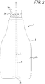
FIG. 2 is a side view illustrating a double-walled container ofFIG. 1 ; -
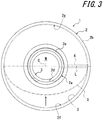
FIG. 3 is a plan view illustrating a double-walled container ofFIG. 1 ; -
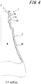
FIG. 4 is a sectional view taken along a line A-A ofFIG.1 ; -
FIG. 5 is a side sectional view illustrating a double-walled container ofFIG. 1 that is fitted with a dispensing cap according to another embodiment of the present disclosure; -
FIG. 6 is a sectional view taken along a line B-B ofFIG. 5 ; -
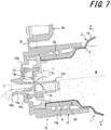
FIG. 7 is a side sectional view illustrating a double-walled container fitted with another dispensing cap, instead of a dispensing cap ofFIG. 5 , according to yet another embodiment of the present disclosure; and -
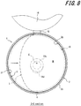
FIG. 8 is a sectional view taken along a line C-C ofFIG. 7 . - The present disclosure will be described in more detail below with reference to the drawings. In the figures,
reference numeral 1 denotes a double-walled container according to embodiments of the present disclosure. As illustrated inFIGs. 1 through 4 , the double-walled container 1 includes anouter layer body 2 and aninner layer body 3. Theinner layer body 3 forms an outer shell of the container. Theinner layer body 3 includes a filling space M, which is configured to contain a content medium, and is disposed on the inner side of theouter layer body 2. - The
outer layer body 2 is made of synthetic resin, such as polyethylene and polypropylene, and theouter layer body 2 has a regular shape. As illustrated inFIGs. 1 and2 , theouter layer body 2 includes a cylindrical-shaped mouth 2a, a cylindrical-shaped trunk 2b, and abottom 2c. Themouth 2a has an open upper side. Thetrunk 2b has a diameter that is larger than that of themouth 2a. Thetrunk 2b also has one end coupled to themouth 2a and the other end closed by thebottom 2c. Theouter layer body 2 in the present embodiment is configured by a mold used for blow molding. The mold may be split into two parts along the center axis C of theouter layer body 2. As illustrated inFIGs. 2 and3 , a parting line L, which corresponds to a split surface of the mold, is formed in themouth 2a, thetrunk 2b, and the bottom 2c. - The
mouth 2a is provided with a single hole (ambient air introduction hole) 2d, which passes through themouth 2a. In the present embodiment, the ambientair introduction hole 2d is provided at a position that is 90 degrees offset in the circumferential direction with respect to the parting line L. The ambientair introduction hole 2d may be provided at any position in the circumferential direction, except for the position of an adhesive strip, which is described later. The ambientair introduction hole 2d may also be provided offset in the direction of the center axis C or provided in thetrunk 2b or the bottom 2c. Furthermore, themouth 2a is provided, on an outer surface thereof excluding the ambientair introduction hole 2d, with ascrew part 2e. Thescrew part 2e is used to fit a dispensing cap, which is described later. - The
inner layer body 3 is made of flexible and thin synthetic resin. In the present embodiment, a material (e.g., ethylene-vinylalcohol copolymer and nylon, such as polyamide) having a low compatibility with theouter layer body 2 is used. - Between the
outer layer body 2 and theinner layer body 3, a singleadhesive strip 4 is disposed. Theadhesive strip 4 extends along the center axis C of theouter layer body 2 and connects theouter layer body 2 and theinner layer body 3. In the present embodiment, as illustrated inFIG. 3 , theadhesive strip 4 is disposed on the parting line L and extends from an end of themouth 2a to a coupling part between thetrunk 2b and the bottom 2c. Additionally, the length and the starting position of theadhesive strip 4 may be selected in various ways. For example, theadhesive strip 4 may extend from the end of themouth 2a to a middle of the bottom 2c or may extend only in thetrunk 2b. - The
outer layer body 2 has an inner surface, which, except for a part thereof in which theadhesive strip 4 is disposed, is configured by aseparation surface 2f (which corresponds to a region extending through 180 degrees in the clockwise direction about the center axis C from an edge of theadhesive strip 4 inFIG. 3 ) and apseudo-adhesive surface 2g (which corresponds to a region extending through 180 degrees in the anti-clockwise direction from the edge of theadhesive strip 4 inFIG. 3 ). Theseparation surface 2f faces the ambientair introduction hole 2d and is separated from an outer surface of theinner layer body 3. Thepseudo-adhesive surface 2g faces theseparation surface 2f and is separably adhered to the outer surface of theinner layer body 3. - The double-
walled container 1 in the present embodiment may be obtained, for example, as follows. Firstly, a laminated parison is extrusion molded. This may be achieved by co-extruding, through a dice used for multi-layer extrusion molding, a tubular-shaped outer layer parison, which is to form theouter layer body 2, a tubular-shaped inner layer parison, which is to form theinner layer body 3, and a longitudinal strip-shaped adhesive layer, which is disposed between the outer layer parison and the inner layer parison and which is to form theadhesive strip 4. Then, the laminated parison is subjected to blow molding in the state where the laminated parison is sandwiched in a mold used for blow molding that is positioned below the dice. In this example, the ambientair introduction hole 2d may be formed with use of a punch or the like after the blow molding. Immediately after the molding, the inner surface of theouter layer body 2, except for the part thereof in which theadhesive strip 4 is disposed, is separatably adhered to the outer surface of theinner layer body 3 over the entire circumference. However, blowing air to theinner layer body 3 through the ambientair introduction hole 2d permits theinner layer body 3 to separate from theouter layer body 2. Thus, theseparation surface 2f is formed. - In the above double-
walled container 1, a dispensingcap 10, which is illustrated inFIGs. 5 through 8 may be fitted to themouth 2a to dispense the content medium contained in the filling space M.The dispensing cap 10, which is illustrated inFIGs. 5 through 8 , includes aninside plug 11, adisplaceable valve body 12, acheck valve 13, and a dispensing cap'smain body 14. The dispensing cap'smain body 14 is also provided, on the side thereof, with acap body 16 integrally via ahinge 15. - The
inside plug 11 includes a throughhole 11a, through which the content medium passes, and a tubular-shapedwall 11b, which has open ends. Theinside plug 11 is disposed in the opening of themouth 2a. Thedisplaceable valve body 12 has a spherical shape. Thedisplaceable valve body 12 is arranged inside the tubular-shapedbody 11b in a manner such that thevalve body 12 is displaceable along the axis line of the tubular-shapedwall 11b. Thecheck valve 13 is configured as a so-called three-piece valve and disposed on an upper surface of theinside plug 11. Thecheck valve 13 has avalve body 13a, which is normally seated on the upper surface of theinside plug 11 to close the throughhole 11a. Additionally, thevalve body 13a does not block the tubular-shapedwall 11b completely, and a gap defined by an elastic piece supporting thevalve body 13a is always unblocked. The dispensing cap'smain body 14 includes aceiling wall 14a, which, together with theinside plug 11, covers the opening of themouth 2a, and afitting tube 14b, which is coupled to an edge of theceiling wall 14a and which is held to themouth 2a. Theceiling wall 14a is provided with a cylindrical-shapeddispensing tube 14c. The dispensingtube 14c is also provided, at a top thereof, with alip 14d, whose tip is curved to the outer side in the radial direction. Furthermore, theceiling wall 14a is provided with avent 14e, through which air may be drawn between theouter layer body 2 and theinner layer body 3. - With the
above dispensing cap 10, when theouter layer body 2 is displaced to a tilted position, the filling space M is pressurized, and thevalve body 13a moves away from theinside plug 11. In conjunction with this movement, the content medium contained in the filling space M is dispensed from the dispensingtube 14c through the throughhole 11a. At this time, thedisplaceable valve body 12 is also displaced inside thetubular wall 11b toward the dispensingtube 14c. Subsequently, when the pressure to theouter layer body 2 is released to return theouter layer body 2 to its original position, the pressure in the filling space M is decreased. Accordingly, thevalve body 13a is seated on theinside plug 11 and thus, closes the throughhole 11a. At this time, thedisplaceable valve body 12 is also returned to its original position. In conjunction with this, the content medium in the dispensingtube 14c is drawn (sucked) back through the always unblocked gap defined by the elastic piece supporting thevalve body 13a. This helps prevent liquid dripping from the dispensingtube 14c. Additionally, as the pressure is released, theouter layer body 2 tries to return to its original shape, and accordingly, negative pressure is generated in space between theouter layer body 2 and theinner layer body 3. The negative pressure in turn draws ambient air into the dispensing cap'smain body 14 through thevent 14e. The ambient air is then introduced between theouter layer body 2 and theinner layer body 3 through the ambientair introduction hole 2d. Thus, only theouter layer body 2 is restored while theinner layer body 3 remains in a volume-reduced, deformed state. - In thus configured double-
walled container 1, the rigidity of theouter layer body 2 is smaller on the side where theseparation surface 2f is positioned than on the side where thepseudo-adhesive surface 2g is positioned. This is due to a reduced thickness by the lack theinner layer body 3 on the side where theseparation surface 2f is positioned. Accordingly, when theouter layer body 2 is pressed by one hand to dispense the content medium, the side where theseparation surface 2f is positioned in theouter layer body 2 undergoes flexure in priority to the side where thepseudo-adhesive surface 2g is positioned in theouter layer body 2. That is to say, compared with an existing double-walled container, in which the opposing parts of theouter layer body 2 are both subject to flexure, less pressure is necessary to dispense the content medium. - Furthermore, in the double-
walled container 1, holding theouter layer body 2 from above facilitates pressing of theouter layer body 2 at the time of displacing theouter layer body 2 to the tilted position to dispense the content medium. In other words, in the above state, balls of the fingers pressing theouter layer body 2 are assumed to be positioned on both sides in the horizontal direction of the center axis of theouter layer body 2. Accordingly, it is preferable to position theseparation surface 2f and thepseudo-adhesive surface 2g on both the sides in the horizontal direction. Preferably, the double-walled container 1 is provided with a guide unit that permits a user to hold theouter layer body 2 in the above state without having to be particularly aware of that. - Examples of the guide unit may include the
hinge 15, which is illustrated inFIGs. 5 through 8 . Thehinge 15 herein is disposed to be positioned above the dispensingcap 10 in the state where theseparation surface 2f and thepseudo-adhesive surface 2g are positioned on both the sides in the horizontal direction and where theouter layer body 2 is displaced to the tilted position. That is to say, when thecap body 16 is opened to dispense the content medium, theouter layer body 2 is held naturally in a position where thehinge 15 is positioned above the dispensing cap 10 (by which the openedcap body 16 is positioned above the dispensing cap) so that thecap body 16 does not prevent dispensing of the content medium. Thus, theseparation surface 2f and thepseudo-adhesive surface 2g are guided to be positioned on both the sides in the horizontal direction, as desired. - Other examples of the guide unit may include the dispensing
tube 14c, which is illustrated inFIGs. 5 and6 . The dispensingtube 14c herein is provided with a lower side part that is longer than remaining parts in the state where theseparation surface 2f and thepseudo-adhesive surface 2g are positioned on both the sides in the horizontal direction and where theouter layer body 2 is displaced to the tilted position. Other examples may also include thelip 14d, which is illustrated inFIGs. 7 and8 . Thelip 14d herein is provided only in the lower side part of the top of the dispensingtube 14c in the state where theseparation surface 2f and thepseudo-adhesive surface 2g are positioned on both the sides in the horizontal direction and where theouter layer body 2 is displaced to the tilted position. Additionally, the guide unit is not limited to any of the above examples, and a variety of configurations may be adopted. For example, the outer surface of theouter layer body 2 may be provided, on the sides thereof where theseparation surface 2f and thepseudo-adhesive surface 2g are positioned, with concave or convex parts against which fingers may be placed. - Additionally, if the area of the
separation surface 2f is too small relative to the area of thepseudo-adhesive surface 2g, theinner layer body 3 might not undergo sufficient volume reduction and deformation when the content medium is dispensed. On the other hand, if the area of theseparation surface 2f is too large relative to the area of thepseudo-adhesive surface 2g, the range of theouter layer body 2 that may be imparted with high priority in terms of ease of flexure is decreased. In contrast, in cases where theseparation surface 2f and thepseudo-adhesive surface 2g are disposed at positions that are 90 degrees offset in the circumferential direction with respect to theadhesive strip 4 as in the present embodiment, the following benefit is provided. That is to say, since substantially one-half of the inner surface of theouter layer body 2 about theadhesive strip 4 forms theseparation surface 2f, and the other half forms thepseudo-adhesive surface 2g, both the functions described above are compatible effectively. -
- 1:
- Double-walled container
- 2:
- Outer layer body
- 2a:
- Mouth
- 2b:
- Trunk
- 2c:
- Bottom
- 2d:
- Ambient air introduction hole
- 2e:
- Screw part
- 2f:
- Separation surface
- 2g:
- Pseudo-adhesive surface
- 3:
- Inner layer body
- 4:
- Adhesive strip
- 10:
- Dispensing cap
- 11:
- Inside plug
- 11a:
- Through hole
- 11b:
- Tubular-shaped wall
- 12:
- Displaceable valve body
- 13:
- Check valve
- 13a:
- Valve body
- 14:
- Dispensing cap's main body
- 14a:
- Ceiling wall
- 14b:
- Fitting tube
- 14c:
- Dispensing tube
- 14d:
- Lip
- 14e:
- Vent
- 15:
- Hinge
- 16:
- Cap body
- C:
- Center axis
- L:
- Parting line
- M:
- Filling space
Claims (6)
- A double-walled container comprising an outer layer body and an inner layer body, the outer layer body including a mouth with an open upper side, a trunk, and a bottom, and the inner layer body including filling space to contain a content medium, being disposed on an inner side of the outer layer body, and being configured to undergo volume reduction and deformation in conjunction with dispensing of the content medium from the filling space, wherein
a single adhesive strip is disposed between the outer layer body and the inner layer body in a manner such that the adhesive strip extends along a center axis of the outer layer body and couples the outer layer body and the inner layer body partially,
the outer layer body is provided, in a position that is offset in a circumferential direction with respect to the adhesive strip, with a single ambient air introduction hole through which ambient air is drawn between the outer layer body and the inner layer body, and
the outer layer body includes an inner surface configured by a separation surface and a pseudo-adhesive surface, the separation surface facing the ambient air introduction hole and being separated from an outer surface of the inner layer body, and the pseudo-adhesive surface facing the separation surface and being separably adhered to the outer surface of the inner layer body. - The double-walled container according to claim 1, further comprising a guide unit that guides the outer layer body into a state where the separation surface and the pseudo-adhesive surface are positioned on both sides in a horizontal direction when the outer layer body is displaced to a tilted position to dispense the content medium.
- The double-walled container according to claim 2, wherein the mouth is fitted with a dispensing cap though which the content medium contained in the filling space is dispensed to outside, the dispensing cap is provided with a cap body that is coupled thereto via a hinge, and the hinge, which is disposed above the dispensing cap in the state where the separation surface and the pseudo-adhesive surface are positioned on both the sides in the horizontal direction and where the outer layer body is displaced to the tilted position, serves as the guide unit.
- The double-walled container according to claim 2, wherein the mouth is fitted with a dispensing cap though which the content medium contained in the filling space is dispensed to outside, the dispensing cap including a ceiling wall covering an opening of the mouth and a dispensing tube rising from the ceiling wall, and the dispensing tube, which is provided with a lower side part that is longer than remaining parts thereof in the state where the separation surface and the pseudo-adhesive surface are positioned on both the sides in the horizontal direction and where the outer layer body is displaced to the tilted position, serves as the guide unit.
- The double-walled container according to claim 2, wherein the mouth is fitted with a dispensing cap though which the content medium contained in the filling space is dispensed to outside, the dispensing cap is provided with a dispensing tube including, at a top thereof, a lip whose tip is curved to an outer side in a radial direction, and the lip, which is provided only in a lower side part of the top in the state where the separation surface and the pseudo-adhesive surface are positioned on both the sides in the horizontal direction and where the outer layer body is displaced to the tilted position, serves as the guide unit.
- The double-walled container according to claim 1, wherein the ambient air introduction hole is provided at a position that is 90 degrees offset in the circumferential direction with respect to the adhesive strip.
Applications Claiming Priority (2)
| Application Number | Priority Date | Filing Date | Title |
|---|---|---|---|
| JP2015017869A JP6489851B2 (en) | 2015-01-30 | 2015-01-30 | Double container |
| PCT/JP2016/000276 WO2016121344A1 (en) | 2015-01-30 | 2016-01-20 | Double-walled container |
Publications (3)
| Publication Number | Publication Date |
|---|---|
| EP3251961A1 true EP3251961A1 (en) | 2017-12-06 |
| EP3251961A4 EP3251961A4 (en) | 2018-10-03 |
| EP3251961B1 EP3251961B1 (en) | 2020-02-05 |
Family
ID=56542968
Family Applications (1)
| Application Number | Title | Priority Date | Filing Date |
|---|---|---|---|
| EP16742949.7A Active EP3251961B1 (en) | 2015-01-30 | 2016-01-20 | Double-walled container |
Country Status (5)
| Country | Link |
|---|---|
| US (2) | US10407232B2 (en) |
| EP (1) | EP3251961B1 (en) |
| JP (1) | JP6489851B2 (en) |
| CN (2) | CN109928002A (en) |
| WO (1) | WO2016121344A1 (en) |
Families Citing this family (5)
| Publication number | Priority date | Publication date | Assignee | Title |
|---|---|---|---|---|
| JP6489851B2 (en) * | 2015-01-30 | 2019-03-27 | 株式会社吉野工業所 | Double container |
| US10822135B2 (en) * | 2015-12-03 | 2020-11-03 | Kyoraku Co., Ltd. | Delaminatable container |
| USD843214S1 (en) * | 2016-07-08 | 2019-03-19 | Chad M Oberly | Disposable container-shape-conforming funnel |
| US10329052B2 (en) | 2016-07-08 | 2019-06-25 | Chad M Oberly | Protective covers for upstanding containers of liquid |
| CN111153013B (en) * | 2018-11-08 | 2022-08-09 | 威玛精密化学科技股份有限公司 | Double-layer container combination |
Family Cites Families (19)
| Publication number | Priority date | Publication date | Assignee | Title |
|---|---|---|---|---|
| US4458830A (en) * | 1981-05-18 | 1984-07-10 | Werding Winfried J | Appliance for discharging a non-compressible liquid, creamy or pasty product under pressure |
| MX171722B (en) * | 1987-07-16 | 1993-11-11 | Paul Wenmaekers | VISCOSE SUBSTANCE DISTRIBUTOR CONTAINER |
| WO1993002926A1 (en) * | 1991-08-05 | 1993-02-18 | Yoshino Kogyosho Co., Ltd. | Bottle of laminate structure and method of making said bottle |
| JP3407292B2 (en) * | 1994-05-31 | 2003-05-19 | 株式会社吉野工業所 | Bottle |
| EP1092633B1 (en) * | 1995-03-10 | 2004-04-28 | Yoshino Kogyosho Co., Ltd. | Laminated peel container |
| EP0893356A1 (en) * | 1997-07-23 | 1999-01-27 | The Procter & Gamble Company | Multilayer pressure resistant container |
| WO2000000058A1 (en) * | 1998-06-30 | 2000-01-06 | Kao Corporation | Container provided with applicator |
| EP2210815B1 (en) * | 2001-08-31 | 2013-05-15 | Yoshino Kogyosho Co., Ltd. | Pouring vessel |
| JP2003137241A (en) | 2001-10-31 | 2003-05-14 | Yoshino Kogyosho Co Ltd | Blow molded container |
| CN1247414C (en) * | 2001-10-31 | 2006-03-29 | 株式会社吉野工业所 | Blow-molded container |
| US6997353B2 (en) * | 2003-03-26 | 2006-02-14 | Airlesssystems | Fluid product dispenser |
| JP5450264B2 (en) * | 2010-05-31 | 2014-03-26 | 株式会社吉野工業所 | Dispensing container |
| JP5667010B2 (en) * | 2011-06-09 | 2015-02-12 | 株式会社吉野工業所 | Discharge container |
| JP6336702B2 (en) * | 2011-08-05 | 2018-06-06 | キッコーマン株式会社 | Discharge container |
| SG11201403052TA (en) * | 2011-12-26 | 2014-10-30 | Yoshino Kogyosho Co Ltd | Squeezable container |
| CN103031327B (en) * | 2012-08-02 | 2015-11-25 | 华东理工大学 | The method of protokaryon bacterium photoinduction gene expression system and regulate gene expression thereof |
| CA3093076C (en) * | 2013-03-29 | 2022-12-06 | Yoshino Kogyosho Co., Ltd. | Laminated bottle |
| US9669973B2 (en) * | 2013-06-28 | 2017-06-06 | Yoshino Kogyosho Co., Ltd. | Double-walled container |
| JP6489851B2 (en) * | 2015-01-30 | 2019-03-27 | 株式会社吉野工業所 | Double container |
-
2015
- 2015-01-30 JP JP2015017869A patent/JP6489851B2/en active Active
-
2016
- 2016-01-20 CN CN201910112037.6A patent/CN109928002A/en active Pending
- 2016-01-20 CN CN201680006049.5A patent/CN107207113B/en active Active
- 2016-01-20 US US15/543,505 patent/US10407232B2/en active Active
- 2016-01-20 EP EP16742949.7A patent/EP3251961B1/en active Active
- 2016-01-20 WO PCT/JP2016/000276 patent/WO2016121344A1/en not_active Ceased
-
2019
- 2019-07-25 US US16/522,428 patent/US10858165B2/en active Active
Also Published As
| Publication number | Publication date |
|---|---|
| US20190344948A1 (en) | 2019-11-14 |
| US20180002093A1 (en) | 2018-01-04 |
| JP6489851B2 (en) | 2019-03-27 |
| JP2016141430A (en) | 2016-08-08 |
| CN107207113A (en) | 2017-09-26 |
| US10858165B2 (en) | 2020-12-08 |
| EP3251961B1 (en) | 2020-02-05 |
| CN107207113B (en) | 2019-03-19 |
| CN109928002A (en) | 2019-06-25 |
| US10407232B2 (en) | 2019-09-10 |
| EP3251961A4 (en) | 2018-10-03 |
| WO2016121344A1 (en) | 2016-08-04 |
Similar Documents
| Publication | Publication Date | Title |
|---|---|---|
| US10858165B2 (en) | Double-walled container | |
| US10457450B2 (en) | Intergral, single material container cap | |
| JP5299697B2 (en) | Blow molded housing with extraction cap | |
| US20100006606A1 (en) | Pumping device with collapsible nozzle | |
| WO2014208096A1 (en) | Double-walled container | |
| EP3251960A1 (en) | Double-walled container | |
| JP2015127215A (en) | Double container | |
| KR20150000592A (en) | Extrusion type cosmetic container | |
| JP6100059B2 (en) | Dispensing container | |
| JP6612115B2 (en) | Container with soy sauce | |
| JP6153855B2 (en) | Dispensing container | |
| JP6199168B2 (en) | Double container | |
| KR200474796Y1 (en) | A Spoid Cosmetic Container Unioned a Discharge Control Unit | |
| JP2017214094A (en) | Double container | |
| WO2015099146A1 (en) | Squeeze container | |
| JP6173892B2 (en) | Double container | |
| JP5937022B2 (en) | Double container | |
| JP2015199542A (en) | Dispensing pump support device and dispensing pump and dispensing container using the same | |
| JP6193175B2 (en) | Double container | |
| JP2015196504A (en) | double container | |
| JP6328066B2 (en) | Double container | |
| JP2023051303A (en) | Spout container | |
| JP2017222368A (en) | Squeeze container | |
| US9278794B2 (en) | Small food storage container | |
| JP2019119450A (en) | Double container |
Legal Events
| Date | Code | Title | Description |
|---|---|---|---|
| STAA | Information on the status of an ep patent application or granted ep patent |
Free format text: STATUS: THE INTERNATIONAL PUBLICATION HAS BEEN MADE |
|
| PUAI | Public reference made under article 153(3) epc to a published international application that has entered the european phase |
Free format text: ORIGINAL CODE: 0009012 |
|
| STAA | Information on the status of an ep patent application or granted ep patent |
Free format text: STATUS: REQUEST FOR EXAMINATION WAS MADE |
|
| 17P | Request for examination filed |
Effective date: 20170714 |
|
| AK | Designated contracting states |
Kind code of ref document: A1 Designated state(s): AL AT BE BG CH CY CZ DE DK EE ES FI FR GB GR HR HU IE IS IT LI LT LU LV MC MK MT NL NO PL PT RO RS SE SI SK SM TR |
|
| AX | Request for extension of the european patent |
Extension state: BA ME |
|
| DAV | Request for validation of the european patent (deleted) | ||
| DAX | Request for extension of the european patent (deleted) | ||
| A4 | Supplementary search report drawn up and despatched |
Effective date: 20180903 |
|
| RIC1 | Information provided on ipc code assigned before grant |
Ipc: B65D 47/32 20060101ALI20180828BHEP Ipc: B29C 49/06 20060101ALI20180828BHEP Ipc: B65D 1/02 20060101AFI20180828BHEP Ipc: B65D 47/08 20060101ALI20180828BHEP Ipc: B65D 47/06 20060101ALI20180828BHEP Ipc: B65D 83/00 20060101ALI20180828BHEP |
|
| STAA | Information on the status of an ep patent application or granted ep patent |
Free format text: STATUS: EXAMINATION IS IN PROGRESS |
|
| 17Q | First examination report despatched |
Effective date: 20190523 |
|
| GRAP | Despatch of communication of intention to grant a patent |
Free format text: ORIGINAL CODE: EPIDOSNIGR1 |
|
| STAA | Information on the status of an ep patent application or granted ep patent |
Free format text: STATUS: GRANT OF PATENT IS INTENDED |
|
| INTG | Intention to grant announced |
Effective date: 20191011 |
|
| RAP1 | Party data changed (applicant data changed or rights of an application transferred) |
Owner name: YOSHINO KOGYOSHO CO., LTD. |
|
| RIN1 | Information on inventor provided before grant (corrected) |
Inventor name: KUTSUZAWA, SHINTARO |
|
| GRAS | Grant fee paid |
Free format text: ORIGINAL CODE: EPIDOSNIGR3 |
|
| GRAA | (expected) grant |
Free format text: ORIGINAL CODE: 0009210 |
|
| STAA | Information on the status of an ep patent application or granted ep patent |
Free format text: STATUS: THE PATENT HAS BEEN GRANTED |
|
| AK | Designated contracting states |
Kind code of ref document: B1 Designated state(s): AL AT BE BG CH CY CZ DE DK EE ES FI FR GB GR HR HU IE IS IT LI LT LU LV MC MK MT NL NO PL PT RO RS SE SI SK SM TR |
|
| REG | Reference to a national code |
Ref country code: GB Ref legal event code: FG4D |
|
| REG | Reference to a national code |
Ref country code: AT Ref legal event code: REF Ref document number: 1229732 Country of ref document: AT Kind code of ref document: T Effective date: 20200215 |
|
| REG | Reference to a national code |
Ref country code: DE Ref legal event code: R096 Ref document number: 602016029120 Country of ref document: DE |
|
| REG | Reference to a national code |
Ref country code: IE Ref legal event code: FG4D |
|
| REG | Reference to a national code |
Ref country code: CH Ref legal event code: EP |
|
| REG | Reference to a national code |
Ref country code: NL Ref legal event code: MP Effective date: 20200205 |
|
| PG25 | Lapsed in a contracting state [announced via postgrant information from national office to epo] |
Ref country code: FI Free format text: LAPSE BECAUSE OF FAILURE TO SUBMIT A TRANSLATION OF THE DESCRIPTION OR TO PAY THE FEE WITHIN THE PRESCRIBED TIME-LIMIT Effective date: 20200205 Ref country code: RS Free format text: LAPSE BECAUSE OF FAILURE TO SUBMIT A TRANSLATION OF THE DESCRIPTION OR TO PAY THE FEE WITHIN THE PRESCRIBED TIME-LIMIT Effective date: 20200205 Ref country code: NO Free format text: LAPSE BECAUSE OF FAILURE TO SUBMIT A TRANSLATION OF THE DESCRIPTION OR TO PAY THE FEE WITHIN THE PRESCRIBED TIME-LIMIT Effective date: 20200505 Ref country code: PT Free format text: LAPSE BECAUSE OF FAILURE TO SUBMIT A TRANSLATION OF THE DESCRIPTION OR TO PAY THE FEE WITHIN THE PRESCRIBED TIME-LIMIT Effective date: 20200628 |
|
| REG | Reference to a national code |
Ref country code: LT Ref legal event code: MG4D |
|
| PG25 | Lapsed in a contracting state [announced via postgrant information from national office to epo] |
Ref country code: IS Free format text: LAPSE BECAUSE OF FAILURE TO SUBMIT A TRANSLATION OF THE DESCRIPTION OR TO PAY THE FEE WITHIN THE PRESCRIBED TIME-LIMIT Effective date: 20200605 Ref country code: GR Free format text: LAPSE BECAUSE OF FAILURE TO SUBMIT A TRANSLATION OF THE DESCRIPTION OR TO PAY THE FEE WITHIN THE PRESCRIBED TIME-LIMIT Effective date: 20200506 Ref country code: BG Free format text: LAPSE BECAUSE OF FAILURE TO SUBMIT A TRANSLATION OF THE DESCRIPTION OR TO PAY THE FEE WITHIN THE PRESCRIBED TIME-LIMIT Effective date: 20200505 Ref country code: HR Free format text: LAPSE BECAUSE OF FAILURE TO SUBMIT A TRANSLATION OF THE DESCRIPTION OR TO PAY THE FEE WITHIN THE PRESCRIBED TIME-LIMIT Effective date: 20200205 Ref country code: LV Free format text: LAPSE BECAUSE OF FAILURE TO SUBMIT A TRANSLATION OF THE DESCRIPTION OR TO PAY THE FEE WITHIN THE PRESCRIBED TIME-LIMIT Effective date: 20200205 Ref country code: SE Free format text: LAPSE BECAUSE OF FAILURE TO SUBMIT A TRANSLATION OF THE DESCRIPTION OR TO PAY THE FEE WITHIN THE PRESCRIBED TIME-LIMIT Effective date: 20200205 |
|
| PG25 | Lapsed in a contracting state [announced via postgrant information from national office to epo] |
Ref country code: NL Free format text: LAPSE BECAUSE OF FAILURE TO SUBMIT A TRANSLATION OF THE DESCRIPTION OR TO PAY THE FEE WITHIN THE PRESCRIBED TIME-LIMIT Effective date: 20200205 |
|
| PG25 | Lapsed in a contracting state [announced via postgrant information from national office to epo] |
Ref country code: SK Free format text: LAPSE BECAUSE OF FAILURE TO SUBMIT A TRANSLATION OF THE DESCRIPTION OR TO PAY THE FEE WITHIN THE PRESCRIBED TIME-LIMIT Effective date: 20200205 Ref country code: DK Free format text: LAPSE BECAUSE OF FAILURE TO SUBMIT A TRANSLATION OF THE DESCRIPTION OR TO PAY THE FEE WITHIN THE PRESCRIBED TIME-LIMIT Effective date: 20200205 Ref country code: ES Free format text: LAPSE BECAUSE OF FAILURE TO SUBMIT A TRANSLATION OF THE DESCRIPTION OR TO PAY THE FEE WITHIN THE PRESCRIBED TIME-LIMIT Effective date: 20200205 Ref country code: RO Free format text: LAPSE BECAUSE OF FAILURE TO SUBMIT A TRANSLATION OF THE DESCRIPTION OR TO PAY THE FEE WITHIN THE PRESCRIBED TIME-LIMIT Effective date: 20200205 Ref country code: LT Free format text: LAPSE BECAUSE OF FAILURE TO SUBMIT A TRANSLATION OF THE DESCRIPTION OR TO PAY THE FEE WITHIN THE PRESCRIBED TIME-LIMIT Effective date: 20200205 Ref country code: CZ Free format text: LAPSE BECAUSE OF FAILURE TO SUBMIT A TRANSLATION OF THE DESCRIPTION OR TO PAY THE FEE WITHIN THE PRESCRIBED TIME-LIMIT Effective date: 20200205 Ref country code: SM Free format text: LAPSE BECAUSE OF FAILURE TO SUBMIT A TRANSLATION OF THE DESCRIPTION OR TO PAY THE FEE WITHIN THE PRESCRIBED TIME-LIMIT Effective date: 20200205 Ref country code: EE Free format text: LAPSE BECAUSE OF FAILURE TO SUBMIT A TRANSLATION OF THE DESCRIPTION OR TO PAY THE FEE WITHIN THE PRESCRIBED TIME-LIMIT Effective date: 20200205 |
|
| REG | Reference to a national code |
Ref country code: DE Ref legal event code: R097 Ref document number: 602016029120 Country of ref document: DE |
|
| REG | Reference to a national code |
Ref country code: AT Ref legal event code: MK05 Ref document number: 1229732 Country of ref document: AT Kind code of ref document: T Effective date: 20200205 |
|
| PLBE | No opposition filed within time limit |
Free format text: ORIGINAL CODE: 0009261 |
|
| STAA | Information on the status of an ep patent application or granted ep patent |
Free format text: STATUS: NO OPPOSITION FILED WITHIN TIME LIMIT |
|
| 26N | No opposition filed |
Effective date: 20201106 |
|
| PG25 | Lapsed in a contracting state [announced via postgrant information from national office to epo] |
Ref country code: IT Free format text: LAPSE BECAUSE OF FAILURE TO SUBMIT A TRANSLATION OF THE DESCRIPTION OR TO PAY THE FEE WITHIN THE PRESCRIBED TIME-LIMIT Effective date: 20200205 Ref country code: AT Free format text: LAPSE BECAUSE OF FAILURE TO SUBMIT A TRANSLATION OF THE DESCRIPTION OR TO PAY THE FEE WITHIN THE PRESCRIBED TIME-LIMIT Effective date: 20200205 |
|
| PG25 | Lapsed in a contracting state [announced via postgrant information from national office to epo] |
Ref country code: SI Free format text: LAPSE BECAUSE OF FAILURE TO SUBMIT A TRANSLATION OF THE DESCRIPTION OR TO PAY THE FEE WITHIN THE PRESCRIBED TIME-LIMIT Effective date: 20200205 Ref country code: PL Free format text: LAPSE BECAUSE OF FAILURE TO SUBMIT A TRANSLATION OF THE DESCRIPTION OR TO PAY THE FEE WITHIN THE PRESCRIBED TIME-LIMIT Effective date: 20200205 |
|
| PG25 | Lapsed in a contracting state [announced via postgrant information from national office to epo] |
Ref country code: MC Free format text: LAPSE BECAUSE OF FAILURE TO SUBMIT A TRANSLATION OF THE DESCRIPTION OR TO PAY THE FEE WITHIN THE PRESCRIBED TIME-LIMIT Effective date: 20200205 |
|
| REG | Reference to a national code |
Ref country code: CH Ref legal event code: PL |
|
| PG25 | Lapsed in a contracting state [announced via postgrant information from national office to epo] |
Ref country code: LU Free format text: LAPSE BECAUSE OF NON-PAYMENT OF DUE FEES Effective date: 20210120 |
|
| REG | Reference to a national code |
Ref country code: BE Ref legal event code: MM Effective date: 20210131 |
|
| PG25 | Lapsed in a contracting state [announced via postgrant information from national office to epo] |
Ref country code: CH Free format text: LAPSE BECAUSE OF NON-PAYMENT OF DUE FEES Effective date: 20210131 Ref country code: LI Free format text: LAPSE BECAUSE OF NON-PAYMENT OF DUE FEES Effective date: 20210131 |
|
| PG25 | Lapsed in a contracting state [announced via postgrant information from national office to epo] |
Ref country code: IE Free format text: LAPSE BECAUSE OF NON-PAYMENT OF DUE FEES Effective date: 20210120 |
|
| PG25 | Lapsed in a contracting state [announced via postgrant information from national office to epo] |
Ref country code: BE Free format text: LAPSE BECAUSE OF NON-PAYMENT OF DUE FEES Effective date: 20210131 |
|
| PG25 | Lapsed in a contracting state [announced via postgrant information from national office to epo] |
Ref country code: CY Free format text: LAPSE BECAUSE OF FAILURE TO SUBMIT A TRANSLATION OF THE DESCRIPTION OR TO PAY THE FEE WITHIN THE PRESCRIBED TIME-LIMIT Effective date: 20200205 |
|
| PG25 | Lapsed in a contracting state [announced via postgrant information from national office to epo] |
Ref country code: HU Free format text: LAPSE BECAUSE OF FAILURE TO SUBMIT A TRANSLATION OF THE DESCRIPTION OR TO PAY THE FEE WITHIN THE PRESCRIBED TIME-LIMIT; INVALID AB INITIO Effective date: 20160120 |
|
| PG25 | Lapsed in a contracting state [announced via postgrant information from national office to epo] |
Ref country code: MK Free format text: LAPSE BECAUSE OF FAILURE TO SUBMIT A TRANSLATION OF THE DESCRIPTION OR TO PAY THE FEE WITHIN THE PRESCRIBED TIME-LIMIT Effective date: 20200205 |
|
| PG25 | Lapsed in a contracting state [announced via postgrant information from national office to epo] |
Ref country code: MT Free format text: LAPSE BECAUSE OF FAILURE TO SUBMIT A TRANSLATION OF THE DESCRIPTION OR TO PAY THE FEE WITHIN THE PRESCRIBED TIME-LIMIT Effective date: 20200205 |
|
| PG25 | Lapsed in a contracting state [announced via postgrant information from national office to epo] |
Ref country code: TR Free format text: LAPSE BECAUSE OF FAILURE TO SUBMIT A TRANSLATION OF THE DESCRIPTION OR TO PAY THE FEE WITHIN THE PRESCRIBED TIME-LIMIT Effective date: 20200205 |
|
| PGFP | Annual fee paid to national office [announced via postgrant information from national office to epo] |
Ref country code: GB Payment date: 20251127 Year of fee payment: 11 |
|
| PGFP | Annual fee paid to national office [announced via postgrant information from national office to epo] |
Ref country code: FR Payment date: 20251128 Year of fee payment: 11 |
|
| PGFP | Annual fee paid to national office [announced via postgrant information from national office to epo] |
Ref country code: DE Payment date: 20251203 Year of fee payment: 11 |