EP3251838A1 - Laminated glass and automobile door - Google Patents
Laminated glass and automobile door Download PDFInfo
- Publication number
- EP3251838A1 EP3251838A1 EP17000951.8A EP17000951A EP3251838A1 EP 3251838 A1 EP3251838 A1 EP 3251838A1 EP 17000951 A EP17000951 A EP 17000951A EP 3251838 A1 EP3251838 A1 EP 3251838A1
- Authority
- EP
- European Patent Office
- Prior art keywords
- laminated glass
- main body
- viscoelastic member
- panel
- interlayer film
- Prior art date
- Legal status (The legal status is an assumption and is not a legal conclusion. Google has not performed a legal analysis and makes no representation as to the accuracy of the status listed.)
- Withdrawn
Links
Images


Classifications
-
- B—PERFORMING OPERATIONS; TRANSPORTING
- B60—VEHICLES IN GENERAL
- B60J—WINDOWS, WINDSCREENS, NON-FIXED ROOFS, DOORS, OR SIMILAR DEVICES FOR VEHICLES; REMOVABLE EXTERNAL PROTECTIVE COVERINGS SPECIALLY ADAPTED FOR VEHICLES
- B60J1/00—Windows; Windscreens; Accessories therefor
- B60J1/08—Windows; Windscreens; Accessories therefor arranged at vehicle sides
- B60J1/12—Windows; Windscreens; Accessories therefor arranged at vehicle sides adjustable
- B60J1/16—Windows; Windscreens; Accessories therefor arranged at vehicle sides adjustable slidable
- B60J1/17—Windows; Windscreens; Accessories therefor arranged at vehicle sides adjustable slidable vertically
-
- B—PERFORMING OPERATIONS; TRANSPORTING
- B32—LAYERED PRODUCTS
- B32B—LAYERED PRODUCTS, i.e. PRODUCTS BUILT-UP OF STRATA OF FLAT OR NON-FLAT, e.g. CELLULAR OR HONEYCOMB, FORM
- B32B17/00—Layered products essentially comprising sheet glass, or glass, slag, or like fibres
- B32B17/06—Layered products essentially comprising sheet glass, or glass, slag, or like fibres comprising glass as the main or only constituent of a layer, next to another layer of a specific material
- B32B17/066—Layered products essentially comprising sheet glass, or glass, slag, or like fibres comprising glass as the main or only constituent of a layer, next to another layer of a specific material of foam
-
- B—PERFORMING OPERATIONS; TRANSPORTING
- B32—LAYERED PRODUCTS
- B32B—LAYERED PRODUCTS, i.e. PRODUCTS BUILT-UP OF STRATA OF FLAT OR NON-FLAT, e.g. CELLULAR OR HONEYCOMB, FORM
- B32B17/00—Layered products essentially comprising sheet glass, or glass, slag, or like fibres
- B32B17/06—Layered products essentially comprising sheet glass, or glass, slag, or like fibres comprising glass as the main or only constituent of a layer, next to another layer of a specific material
- B32B17/10—Layered products essentially comprising sheet glass, or glass, slag, or like fibres comprising glass as the main or only constituent of a layer, next to another layer of a specific material of synthetic resin
- B32B17/10005—Layered products essentially comprising sheet glass, or glass, slag, or like fibres comprising glass as the main or only constituent of a layer, next to another layer of a specific material of synthetic resin laminated safety glass or glazing
- B32B17/10009—Layered products essentially comprising sheet glass, or glass, slag, or like fibres comprising glass as the main or only constituent of a layer, next to another layer of a specific material of synthetic resin laminated safety glass or glazing characterized by the number, the constitution or treatment of glass sheets
- B32B17/10036—Layered products essentially comprising sheet glass, or glass, slag, or like fibres comprising glass as the main or only constituent of a layer, next to another layer of a specific material of synthetic resin laminated safety glass or glazing characterized by the number, the constitution or treatment of glass sheets comprising two outer glass sheets
-
- B—PERFORMING OPERATIONS; TRANSPORTING
- B32—LAYERED PRODUCTS
- B32B—LAYERED PRODUCTS, i.e. PRODUCTS BUILT-UP OF STRATA OF FLAT OR NON-FLAT, e.g. CELLULAR OR HONEYCOMB, FORM
- B32B17/00—Layered products essentially comprising sheet glass, or glass, slag, or like fibres
- B32B17/06—Layered products essentially comprising sheet glass, or glass, slag, or like fibres comprising glass as the main or only constituent of a layer, next to another layer of a specific material
- B32B17/10—Layered products essentially comprising sheet glass, or glass, slag, or like fibres comprising glass as the main or only constituent of a layer, next to another layer of a specific material of synthetic resin
- B32B17/10005—Layered products essentially comprising sheet glass, or glass, slag, or like fibres comprising glass as the main or only constituent of a layer, next to another layer of a specific material of synthetic resin laminated safety glass or glazing
- B32B17/10165—Functional features of the laminated safety glass or glazing
- B32B17/10174—Coatings of a metallic or dielectric material on a constituent layer of glass or polymer
-
- B—PERFORMING OPERATIONS; TRANSPORTING
- B32—LAYERED PRODUCTS
- B32B—LAYERED PRODUCTS, i.e. PRODUCTS BUILT-UP OF STRATA OF FLAT OR NON-FLAT, e.g. CELLULAR OR HONEYCOMB, FORM
- B32B17/00—Layered products essentially comprising sheet glass, or glass, slag, or like fibres
- B32B17/06—Layered products essentially comprising sheet glass, or glass, slag, or like fibres comprising glass as the main or only constituent of a layer, next to another layer of a specific material
- B32B17/10—Layered products essentially comprising sheet glass, or glass, slag, or like fibres comprising glass as the main or only constituent of a layer, next to another layer of a specific material of synthetic resin
- B32B17/10005—Layered products essentially comprising sheet glass, or glass, slag, or like fibres comprising glass as the main or only constituent of a layer, next to another layer of a specific material of synthetic resin laminated safety glass or glazing
- B32B17/10165—Functional features of the laminated safety glass or glazing
- B32B17/10293—Edge features, e.g. inserts or holes
-
- B—PERFORMING OPERATIONS; TRANSPORTING
- B32—LAYERED PRODUCTS
- B32B—LAYERED PRODUCTS, i.e. PRODUCTS BUILT-UP OF STRATA OF FLAT OR NON-FLAT, e.g. CELLULAR OR HONEYCOMB, FORM
- B32B17/00—Layered products essentially comprising sheet glass, or glass, slag, or like fibres
- B32B17/06—Layered products essentially comprising sheet glass, or glass, slag, or like fibres comprising glass as the main or only constituent of a layer, next to another layer of a specific material
- B32B17/10—Layered products essentially comprising sheet glass, or glass, slag, or like fibres comprising glass as the main or only constituent of a layer, next to another layer of a specific material of synthetic resin
- B32B17/10005—Layered products essentially comprising sheet glass, or glass, slag, or like fibres comprising glass as the main or only constituent of a layer, next to another layer of a specific material of synthetic resin laminated safety glass or glazing
- B32B17/1055—Layered products essentially comprising sheet glass, or glass, slag, or like fibres comprising glass as the main or only constituent of a layer, next to another layer of a specific material of synthetic resin laminated safety glass or glazing characterized by the resin layer, i.e. interlayer
- B32B17/10761—Layered products essentially comprising sheet glass, or glass, slag, or like fibres comprising glass as the main or only constituent of a layer, next to another layer of a specific material of synthetic resin laminated safety glass or glazing characterized by the resin layer, i.e. interlayer containing vinyl acetal
-
- B—PERFORMING OPERATIONS; TRANSPORTING
- B32—LAYERED PRODUCTS
- B32B—LAYERED PRODUCTS, i.e. PRODUCTS BUILT-UP OF STRATA OF FLAT OR NON-FLAT, e.g. CELLULAR OR HONEYCOMB, FORM
- B32B17/00—Layered products essentially comprising sheet glass, or glass, slag, or like fibres
- B32B17/06—Layered products essentially comprising sheet glass, or glass, slag, or like fibres comprising glass as the main or only constituent of a layer, next to another layer of a specific material
- B32B17/10—Layered products essentially comprising sheet glass, or glass, slag, or like fibres comprising glass as the main or only constituent of a layer, next to another layer of a specific material of synthetic resin
- B32B17/10005—Layered products essentially comprising sheet glass, or glass, slag, or like fibres comprising glass as the main or only constituent of a layer, next to another layer of a specific material of synthetic resin laminated safety glass or glazing
- B32B17/1055—Layered products essentially comprising sheet glass, or glass, slag, or like fibres comprising glass as the main or only constituent of a layer, next to another layer of a specific material of synthetic resin laminated safety glass or glazing characterized by the resin layer, i.e. interlayer
- B32B17/1077—Layered products essentially comprising sheet glass, or glass, slag, or like fibres comprising glass as the main or only constituent of a layer, next to another layer of a specific material of synthetic resin laminated safety glass or glazing characterized by the resin layer, i.e. interlayer containing polyurethane
-
- B—PERFORMING OPERATIONS; TRANSPORTING
- B32—LAYERED PRODUCTS
- B32B—LAYERED PRODUCTS, i.e. PRODUCTS BUILT-UP OF STRATA OF FLAT OR NON-FLAT, e.g. CELLULAR OR HONEYCOMB, FORM
- B32B17/00—Layered products essentially comprising sheet glass, or glass, slag, or like fibres
- B32B17/06—Layered products essentially comprising sheet glass, or glass, slag, or like fibres comprising glass as the main or only constituent of a layer, next to another layer of a specific material
- B32B17/10—Layered products essentially comprising sheet glass, or glass, slag, or like fibres comprising glass as the main or only constituent of a layer, next to another layer of a specific material of synthetic resin
- B32B17/10005—Layered products essentially comprising sheet glass, or glass, slag, or like fibres comprising glass as the main or only constituent of a layer, next to another layer of a specific material of synthetic resin laminated safety glass or glazing
- B32B17/1055—Layered products essentially comprising sheet glass, or glass, slag, or like fibres comprising glass as the main or only constituent of a layer, next to another layer of a specific material of synthetic resin laminated safety glass or glazing characterized by the resin layer, i.e. interlayer
- B32B17/10788—Layered products essentially comprising sheet glass, or glass, slag, or like fibres comprising glass as the main or only constituent of a layer, next to another layer of a specific material of synthetic resin laminated safety glass or glazing characterized by the resin layer, i.e. interlayer containing ethylene vinylacetate
-
- B—PERFORMING OPERATIONS; TRANSPORTING
- B32—LAYERED PRODUCTS
- B32B—LAYERED PRODUCTS, i.e. PRODUCTS BUILT-UP OF STRATA OF FLAT OR NON-FLAT, e.g. CELLULAR OR HONEYCOMB, FORM
- B32B25/00—Layered products comprising a layer of natural or synthetic rubber
- B32B25/04—Layered products comprising a layer of natural or synthetic rubber comprising rubber as the main or only constituent of a layer, which is next to another layer of the same or of a different material
-
- B—PERFORMING OPERATIONS; TRANSPORTING
- B32—LAYERED PRODUCTS
- B32B—LAYERED PRODUCTS, i.e. PRODUCTS BUILT-UP OF STRATA OF FLAT OR NON-FLAT, e.g. CELLULAR OR HONEYCOMB, FORM
- B32B27/00—Layered products comprising a layer of synthetic resin
- B32B27/06—Layered products comprising a layer of synthetic resin as the main or only constituent of a layer, which is next to another layer of the same or of a different material
-
- B—PERFORMING OPERATIONS; TRANSPORTING
- B32—LAYERED PRODUCTS
- B32B—LAYERED PRODUCTS, i.e. PRODUCTS BUILT-UP OF STRATA OF FLAT OR NON-FLAT, e.g. CELLULAR OR HONEYCOMB, FORM
- B32B27/00—Layered products comprising a layer of synthetic resin
- B32B27/18—Layered products comprising a layer of synthetic resin characterised by the use of special additives
- B32B27/20—Layered products comprising a layer of synthetic resin characterised by the use of special additives using fillers, pigments, thixotroping agents
-
- B—PERFORMING OPERATIONS; TRANSPORTING
- B32—LAYERED PRODUCTS
- B32B—LAYERED PRODUCTS, i.e. PRODUCTS BUILT-UP OF STRATA OF FLAT OR NON-FLAT, e.g. CELLULAR OR HONEYCOMB, FORM
- B32B27/00—Layered products comprising a layer of synthetic resin
- B32B27/18—Layered products comprising a layer of synthetic resin characterised by the use of special additives
- B32B27/22—Layered products comprising a layer of synthetic resin characterised by the use of special additives using plasticisers
-
- B—PERFORMING OPERATIONS; TRANSPORTING
- B32—LAYERED PRODUCTS
- B32B—LAYERED PRODUCTS, i.e. PRODUCTS BUILT-UP OF STRATA OF FLAT OR NON-FLAT, e.g. CELLULAR OR HONEYCOMB, FORM
- B32B27/00—Layered products comprising a layer of synthetic resin
- B32B27/28—Layered products comprising a layer of synthetic resin comprising synthetic resins not wholly covered by any one of the sub-groups B32B27/30 - B32B27/42
-
- B—PERFORMING OPERATIONS; TRANSPORTING
- B32—LAYERED PRODUCTS
- B32B—LAYERED PRODUCTS, i.e. PRODUCTS BUILT-UP OF STRATA OF FLAT OR NON-FLAT, e.g. CELLULAR OR HONEYCOMB, FORM
- B32B27/00—Layered products comprising a layer of synthetic resin
- B32B27/30—Layered products comprising a layer of synthetic resin comprising vinyl (co)polymers; comprising acrylic (co)polymers
- B32B27/304—Layered products comprising a layer of synthetic resin comprising vinyl (co)polymers; comprising acrylic (co)polymers comprising vinyl halide (co)polymers, e.g. PVC, PVDC, PVF, PVDF
-
- B—PERFORMING OPERATIONS; TRANSPORTING
- B32—LAYERED PRODUCTS
- B32B—LAYERED PRODUCTS, i.e. PRODUCTS BUILT-UP OF STRATA OF FLAT OR NON-FLAT, e.g. CELLULAR OR HONEYCOMB, FORM
- B32B27/00—Layered products comprising a layer of synthetic resin
- B32B27/32—Layered products comprising a layer of synthetic resin comprising polyolefins
- B32B27/325—Layered products comprising a layer of synthetic resin comprising polyolefins comprising polycycloolefins
-
- B—PERFORMING OPERATIONS; TRANSPORTING
- B32—LAYERED PRODUCTS
- B32B—LAYERED PRODUCTS, i.e. PRODUCTS BUILT-UP OF STRATA OF FLAT OR NON-FLAT, e.g. CELLULAR OR HONEYCOMB, FORM
- B32B27/00—Layered products comprising a layer of synthetic resin
- B32B27/40—Layered products comprising a layer of synthetic resin comprising polyurethanes
-
- B—PERFORMING OPERATIONS; TRANSPORTING
- B32—LAYERED PRODUCTS
- B32B—LAYERED PRODUCTS, i.e. PRODUCTS BUILT-UP OF STRATA OF FLAT OR NON-FLAT, e.g. CELLULAR OR HONEYCOMB, FORM
- B32B5/00—Layered products characterised by the non- homogeneity or physical structure, i.e. comprising a fibrous, filamentary, particulate or foam layer; Layered products characterised by having a layer differing constitutionally or physically in different parts
- B32B5/18—Layered products characterised by the non- homogeneity or physical structure, i.e. comprising a fibrous, filamentary, particulate or foam layer; Layered products characterised by having a layer differing constitutionally or physically in different parts characterised by features of a layer of foamed material
-
- B—PERFORMING OPERATIONS; TRANSPORTING
- B32—LAYERED PRODUCTS
- B32B—LAYERED PRODUCTS, i.e. PRODUCTS BUILT-UP OF STRATA OF FLAT OR NON-FLAT, e.g. CELLULAR OR HONEYCOMB, FORM
- B32B7/00—Layered products characterised by the relation between layers; Layered products characterised by the relative orientation of features between layers, or by the relative values of a measurable parameter between layers, i.e. products comprising layers having different physical, chemical or physicochemical properties; Layered products characterised by the interconnection of layers
- B32B7/04—Interconnection of layers
- B32B7/12—Interconnection of layers using interposed adhesives or interposed materials with bonding properties
-
- B—PERFORMING OPERATIONS; TRANSPORTING
- B60—VEHICLES IN GENERAL
- B60J—WINDOWS, WINDSCREENS, NON-FIXED ROOFS, DOORS, OR SIMILAR DEVICES FOR VEHICLES; REMOVABLE EXTERNAL PROTECTIVE COVERINGS SPECIALLY ADAPTED FOR VEHICLES
- B60J10/00—Sealing arrangements
- B60J10/50—Sealing arrangements characterised by means for prevention or reduction of noise, e.g. of rattling or vibration of windows
-
- B—PERFORMING OPERATIONS; TRANSPORTING
- B60—VEHICLES IN GENERAL
- B60J—WINDOWS, WINDSCREENS, NON-FIXED ROOFS, DOORS, OR SIMILAR DEVICES FOR VEHICLES; REMOVABLE EXTERNAL PROTECTIVE COVERINGS SPECIALLY ADAPTED FOR VEHICLES
- B60J10/00—Sealing arrangements
- B60J10/70—Sealing arrangements specially adapted for windows or windscreens
- B60J10/74—Sealing arrangements specially adapted for windows or windscreens for sliding window panes, e.g. sash guides
- B60J10/75—Sealing arrangements specially adapted for windows or windscreens for sliding window panes, e.g. sash guides for sealing the lower part of the panes
-
- B—PERFORMING OPERATIONS; TRANSPORTING
- B32—LAYERED PRODUCTS
- B32B—LAYERED PRODUCTS, i.e. PRODUCTS BUILT-UP OF STRATA OF FLAT OR NON-FLAT, e.g. CELLULAR OR HONEYCOMB, FORM
- B32B2250/00—Layers arrangement
- B32B2250/03—3 layers
-
- B—PERFORMING OPERATIONS; TRANSPORTING
- B32—LAYERED PRODUCTS
- B32B—LAYERED PRODUCTS, i.e. PRODUCTS BUILT-UP OF STRATA OF FLAT OR NON-FLAT, e.g. CELLULAR OR HONEYCOMB, FORM
- B32B2262/00—Composition or structural features of fibres which form a fibrous or filamentary layer or are present as additives
- B32B2262/02—Synthetic macromolecular fibres
-
- B—PERFORMING OPERATIONS; TRANSPORTING
- B32—LAYERED PRODUCTS
- B32B—LAYERED PRODUCTS, i.e. PRODUCTS BUILT-UP OF STRATA OF FLAT OR NON-FLAT, e.g. CELLULAR OR HONEYCOMB, FORM
- B32B2262/00—Composition or structural features of fibres which form a fibrous or filamentary layer or are present as additives
- B32B2262/06—Vegetal fibres
-
- B—PERFORMING OPERATIONS; TRANSPORTING
- B32—LAYERED PRODUCTS
- B32B—LAYERED PRODUCTS, i.e. PRODUCTS BUILT-UP OF STRATA OF FLAT OR NON-FLAT, e.g. CELLULAR OR HONEYCOMB, FORM
- B32B2262/00—Composition or structural features of fibres which form a fibrous or filamentary layer or are present as additives
- B32B2262/10—Inorganic fibres
- B32B2262/101—Glass fibres
-
- B—PERFORMING OPERATIONS; TRANSPORTING
- B32—LAYERED PRODUCTS
- B32B—LAYERED PRODUCTS, i.e. PRODUCTS BUILT-UP OF STRATA OF FLAT OR NON-FLAT, e.g. CELLULAR OR HONEYCOMB, FORM
- B32B2262/00—Composition or structural features of fibres which form a fibrous or filamentary layer or are present as additives
- B32B2262/10—Inorganic fibres
- B32B2262/106—Carbon fibres, e.g. graphite fibres
-
- B—PERFORMING OPERATIONS; TRANSPORTING
- B32—LAYERED PRODUCTS
- B32B—LAYERED PRODUCTS, i.e. PRODUCTS BUILT-UP OF STRATA OF FLAT OR NON-FLAT, e.g. CELLULAR OR HONEYCOMB, FORM
- B32B2264/00—Composition or properties of particles which form a particulate layer or are present as additives
- B32B2264/02—Synthetic macromolecular particles
- B32B2264/0214—Particles made of materials belonging to B32B27/00
- B32B2264/0228—Vinyl resin particles, e.g. polyvinyl acetate, polyvinyl alcohol polymers or ethylene-vinyl acetate copolymers
- B32B2264/0235—Aromatic vinyl resin, e.g. styrenic (co)polymers
-
- B—PERFORMING OPERATIONS; TRANSPORTING
- B32—LAYERED PRODUCTS
- B32B—LAYERED PRODUCTS, i.e. PRODUCTS BUILT-UP OF STRATA OF FLAT OR NON-FLAT, e.g. CELLULAR OR HONEYCOMB, FORM
- B32B2264/00—Composition or properties of particles which form a particulate layer or are present as additives
- B32B2264/02—Synthetic macromolecular particles
- B32B2264/0214—Particles made of materials belonging to B32B27/00
- B32B2264/025—Acrylic resin particles, e.g. polymethyl methacrylate or ethylene-acrylate copolymers
-
- B—PERFORMING OPERATIONS; TRANSPORTING
- B32—LAYERED PRODUCTS
- B32B—LAYERED PRODUCTS, i.e. PRODUCTS BUILT-UP OF STRATA OF FLAT OR NON-FLAT, e.g. CELLULAR OR HONEYCOMB, FORM
- B32B2264/00—Composition or properties of particles which form a particulate layer or are present as additives
- B32B2264/02—Synthetic macromolecular particles
- B32B2264/0214—Particles made of materials belonging to B32B27/00
- B32B2264/0278—Polyester particles
-
- B—PERFORMING OPERATIONS; TRANSPORTING
- B32—LAYERED PRODUCTS
- B32B—LAYERED PRODUCTS, i.e. PRODUCTS BUILT-UP OF STRATA OF FLAT OR NON-FLAT, e.g. CELLULAR OR HONEYCOMB, FORM
- B32B2264/00—Composition or properties of particles which form a particulate layer or are present as additives
- B32B2264/10—Inorganic particles
- B32B2264/102—Oxide or hydroxide
-
- B—PERFORMING OPERATIONS; TRANSPORTING
- B32—LAYERED PRODUCTS
- B32B—LAYERED PRODUCTS, i.e. PRODUCTS BUILT-UP OF STRATA OF FLAT OR NON-FLAT, e.g. CELLULAR OR HONEYCOMB, FORM
- B32B2264/00—Composition or properties of particles which form a particulate layer or are present as additives
- B32B2264/10—Inorganic particles
- B32B2264/104—Oxysalt, e.g. carbonate, sulfate, phosphate or nitrate particles
-
- B—PERFORMING OPERATIONS; TRANSPORTING
- B32—LAYERED PRODUCTS
- B32B—LAYERED PRODUCTS, i.e. PRODUCTS BUILT-UP OF STRATA OF FLAT OR NON-FLAT, e.g. CELLULAR OR HONEYCOMB, FORM
- B32B2307/00—Properties of the layers or laminate
- B32B2307/10—Properties of the layers or laminate having particular acoustical properties
- B32B2307/102—Insulating
-
- B—PERFORMING OPERATIONS; TRANSPORTING
- B32—LAYERED PRODUCTS
- B32B—LAYERED PRODUCTS, i.e. PRODUCTS BUILT-UP OF STRATA OF FLAT OR NON-FLAT, e.g. CELLULAR OR HONEYCOMB, FORM
- B32B2307/00—Properties of the layers or laminate
- B32B2307/50—Properties of the layers or laminate having particular mechanical properties
- B32B2307/536—Hardness
-
- B—PERFORMING OPERATIONS; TRANSPORTING
- B32—LAYERED PRODUCTS
- B32B—LAYERED PRODUCTS, i.e. PRODUCTS BUILT-UP OF STRATA OF FLAT OR NON-FLAT, e.g. CELLULAR OR HONEYCOMB, FORM
- B32B2307/00—Properties of the layers or laminate
- B32B2307/70—Other properties
- B32B2307/732—Dimensional properties
-
- B—PERFORMING OPERATIONS; TRANSPORTING
- B32—LAYERED PRODUCTS
- B32B—LAYERED PRODUCTS, i.e. PRODUCTS BUILT-UP OF STRATA OF FLAT OR NON-FLAT, e.g. CELLULAR OR HONEYCOMB, FORM
- B32B2605/00—Vehicles
- B32B2605/006—Transparent parts other than made from inorganic glass, e.g. polycarbonate glazings
-
- B—PERFORMING OPERATIONS; TRANSPORTING
- B32—LAYERED PRODUCTS
- B32B—LAYERED PRODUCTS, i.e. PRODUCTS BUILT-UP OF STRATA OF FLAT OR NON-FLAT, e.g. CELLULAR OR HONEYCOMB, FORM
- B32B2605/00—Vehicles
- B32B2605/08—Cars
-
- Y—GENERAL TAGGING OF NEW TECHNOLOGICAL DEVELOPMENTS; GENERAL TAGGING OF CROSS-SECTIONAL TECHNOLOGIES SPANNING OVER SEVERAL SECTIONS OF THE IPC; TECHNICAL SUBJECTS COVERED BY FORMER USPC CROSS-REFERENCE ART COLLECTIONS [XRACs] AND DIGESTS
- Y10—TECHNICAL SUBJECTS COVERED BY FORMER USPC
- Y10T—TECHNICAL SUBJECTS COVERED BY FORMER US CLASSIFICATION
- Y10T428/00—Stock material or miscellaneous articles
- Y10T428/26—Web or sheet containing structurally defined element or component, the element or component having a specified physical dimension
Definitions
- the present invention relates to a laminated glass and an automobile door, and particularly, relates to a laminated glass for an automobile door that has a high rigidity and is capable of achieving a high sound insulating property when being installed in an automobile door and an automobile door including the laminated glass.
- the laminated glass to be used as an openable and closable window glass in an automobile door has also been required to be reduced in weight.
- the laminated glass of the automobile door has been required to have a sound insulating property that allows blocking of wind noises and body vibration sounds during running conventionally.
- the laminated glass typically has a composition in which an interlayer film is sandwiched between a pair of glass plates, and as for the laminated glass for an automobile door, there has been known a technique of enhancing the sound insulating property by adjusting materials and a composition of the interlayer film (see Patent Reference 1, for example).
- the thinner glass plate necessarily entails a reduced strength of the laminated glass.
- the sound insulating property, the weight reduction, and the strength maintenance of the laminated glass are tried to be achieved at the same time.
- use of a highly rigid interlayer film causes a phenomenon in which the sound insulating property deteriorates in a specific frequency region, to thus be a problem.
- the present invention has been made from the above-described viewpoints, and an object thereof is to provide laminated glass for an automobile door that is capable of being reduced in weight by having a high rigidity and at the same time, capable of achieving a high sound insulating property when being installed in an automobile door, and an automobile door that includes the laminated glass and has excellent sound insulating performance while corresponding to a weight reduction.
- a laminated glass according to the present invention is a laminated glass provided in an automobile door panel including two panel boards facing each other and seal members provided on facing surfaces of the panel boards at regions along a beltline, the laminated glass being openable and closable by being provided between the two panel boards so as to slide between the seal members, the laminated glass including:
- An automobile door according to the present invention includes the laminated glass according to the present invention.
- the present invention it is possible to provide laminated glass for an automobile door that is capable of being reduced in weight by having a high rigidity and at the same time, capable of achieving a high sound insulating property when being installed in an automobile door, and an automobile door that includes the laminated glass and has excellent sound insulating performance while corresponding to a weight reduction.
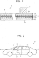
- FIG. 1 is a cross-sectional view of a laminated glass according to the embodiment
- FIG. 2 is a side view of an automobile in which an automobile door including the laminated glass according to the embodiment is installed.
- FIG. 3 is a cross-sectional view taken along the A-A'-A" line in FIG. 2 that schematically illustrates a state at a closed time and a state at an opened time when the laminated glass according to the embodiment in FIG. 1 is used in the automobile door illustrated in FIG. 2 .
- a laminated glass 1 illustrated in FIG. 1 is a laminated glass for an automobile door.
- the laminated glass 1 includes a laminated glass main body 11 composed of two glass plates 11A, 11B and an interlayer film 12 held sandwiched between the glass plates, and a viscoelastic member 13 provided at a position, on a surface Sa on the glass plate 11A side of the laminated glass main body 11, to be a lower portion when the laminated glass 1 is used as a composing member of an automobile door.
- the viscoelastic member 13, as will be explained below, abuts on a seal member or a panel board that an automobile door panel has, and seals a gap between the seal member or the panel board and the laminated glass main body 11 at a closed time of the laminated glass 1.
- the interlayer film 12 has a three-layer laminated structure in which two skin layers 12A, 12B hold a core layer 12C sandwiched therebetween, and has a storage modulus G' of 1.5 ⁇ 10 6 Pa or more, which is measured by a dynamic viscoelasticity test under a condition at a frequency of 1 Hz, a dynamic shearing strain of 0.015%, and a temperature of 20°C.
- the storage modulus G' of the interlayer film is 1.5 ⁇ 10 6 Pa or more, the interlayer film is allowed to have a high rigidity and the glass plates composing the laminated glass together can be reduced in thickness, resulting in a weight reduction of the laminated glass.
- the laminated glass 1 according to the embodiment is one in which the viscoelastic member 13 is provided on the laminated glass main body 11 so as to form a later-described sound insulating structure, to thereby suppress the above-described deterioration of sound insulating performance.
- the "storage modulus G''' is a storage modulus G' measured by a dynamic viscoelasticity test under the condition at a frequency of 1 Hz, a dynamic shearing strain of 0.015%, and a temperature of 20°C unless otherwise noted.
- the storage modulus G' can be measured by a shearing method, for example, by a dynamic viscoelasticity test using a Rheometer MCR301 manufactured by Anton Paar GmbH.
- the interlayer film 12 has a three-layer laminated structure in the laminated glass 1, the number of layers is not limited as long as the storage modulus G' is 1.5 ⁇ 10 6 Pa or more.
- the interlayer film 12 may be a single-layer film, or may also be a laminated film in which a plurality of layers are laminated.
- the number of layers is preferably two to five, and from the viewpoint of easily achieving the above-described two properties in a balanced manner, three layers are particularly preferred.
- the laminated glass 1 composes a part of an automobile door 3 included in an automobile 10 illustrated in FIG. 2 , for example.
- the automobile door 3 is composed of an automobile door panel (to be also referred to as a "door panel” simply, hereinafter) 2 and the laminated glass 1.
- the door panel 2 includes two panel boards facing each other (in FIG. 2 , only a panel board 22 on an automobile exterior side is illustrated) and seal members provided on facing surfaces of the panel boards at regions along a beltline L (to be also referred to as "beltline portions” hereinafter) Ls.
- the laminated glass 1 is provided in a liftable manner between the two panel boards 21 and 22 of the door panel 2 so as to slide between seal members 41 and 42 ( FIG. 3 ).
- the beltline L is a line connecting upper ends of the panel boards 22 of the front and rear automobile doors 3.
- the beltline portion Ls is a region having a predetermined width from the upper ends of the panel boards toward a downside along the beltline L.
- the laminated glass 1 is provided in the door panel 2 in a liftable manner, to thereby be openable and closable.
- the laminated glass 1 being openable and closable means that a window opening portion W located at an upside of the automobile door 3 illustrated in FIG. 2 is free to be opened and closed by the laminated glass 1 being raised and lowered. That is, at a closed time of the laminated glass 1, the window opening portion W is closed by the laminated glass 1, and at an opened time of the laminated glass 1, the window opening portion W is in a state of being opened.
- FIG. 3 is a view schematically illustrating a cross-sectional view taken along the A-A'-A" line of the automobile door 3 including the laminated glass 1 in FIG. 2 at a closed time and at an opened time of the laminated glass 1.
- FIG. 3 illustrates the two panel boards 21 and 22 facing each other and the seal members 41 and 42 provided on the facing surfaces of the panel boards 21 and 22, at the beltline portions Ls which are included in the door panel 2.
- the laminated glass 1 is installed in the door panel 2 so that the surface Sa on the glass plate 11A side of the laminated glass main body 11 is located on the automobile interior side and a surface Sb on the glass plate 11B side is located on the automobile exterior side.
- the laminated glass 1 at a closed time is lowered in an arrow P1 direction, and a state where it is lowered completely is an opened time. Further, the laminated glass 1 at an opened time is raised in an arrow P2 direction, and a state where it is raised completely is a closed time.
- the panel board located on the automobile interior side is referred to as an inner panel and the panel board located on the automobile exterior side is referred to as an outer panel.
- the seal member located on the automobile interior side is referred to as an inner seal member and the seal member located on the automobile exterior side is referred to as an outer seal member.
- the inner seal member 41 has two lip portions vertically on the laminated glass 1 side, that is, an upper inner lip 411 and a lower inner lip 412, while the outer seal member 42 has an upper outer lip 421 and a lower outer lip 422 on the laminated glass 1 side similarly.
- the viscoelastic member 13 that the laminated glass 1 has is constrained between the laminated glass main body 11 and the inner panel 21 to thereby form a constraining type vibration suppressing structure. Therefore, it is possible to sufficiently suppress vibrations of the laminated glass 1 and achieve a high sound insulating effect in the automobile interior at a closed time of the laminated glass 1.
- a cause of vibration of the laminated glass there can be cited propagation of road noise from the door panel to the laminated glass, propagation of engine noise, and so on.
- the laminated glass main body 11 has the pair of glass plates 11A and 11B facing each other and the interlayer film 12 arranged so as to be held sandwiched between the pair of glass plates 11A and 11B.
- the interlayer film 12 is composed of three layers: the pair of skin layers 12A and 12B; and the core layer 12C arranged so as to be held sandwiched between the skin layers 12A and 12B.
- the interlayer film 12 is arranged so that the skin layer 12A is located on the glass plate 11A side and the skin layer 12B is located on the glass plate 11B side.
- the pair of glass plates 11A and 11B and the three layers 12A, 12B, and 12C composing the interlayer film have main surfaces with substantially the same shape and same dimensions.
- the shape and the size of the main surface of the laminated glass main body 11 are the shape and the size that allow the viscoelastic member 13 to seal the gap between the inner panel 21 and the laminated glass main body 11 at the downside in the beltline portion in a state of the window opening portion of the automobile door being closed at a closed time of the laminated glass.
- Each thickness of the pair of glass plates 11A and 11B in the laminated glass main body 11 preferably falls within a range of 0.3 mm to 1.8 mm.
- a rigidity when the glass plates 11 A and 11B are combined with the following interlayer film to fabricate the laminated glass is secured easily.
- each of the thicknesses of the glass plates 11A and 11B being 1.8 mm or less, the weight reduction when the glass plates 11A and 11B are combined with the interlayer film to fabricate the laminated glass is achieved easily.
- Each of the thicknesses of the glass plates 11A and 11B preferably falls within a range of 1.0 mm to 1.8 mm, and more preferably falls within a range of 1.5 mm to 1.8 mm.
- the thicknesses of the pair of glass plates 11A and 11B may be the same or different from each other. In the case where the thicknesses of the pair of glass plates 11A and 11B are different, the thickness of the glass plate located on the automobile interior side when the laminated glass 1 is installed in the door panel 2 is preferred to be smaller than the thickness of the glass plate located on the automobile exterior side.
- the glass plate located on the automobile interior side is the glass plate 11A.
- the thickness of the glass plate 11A on the automobile interior side is preferably 0.3 mm to 1.8 mm, more preferably 1.0 mm to 1.8 mm, and still more preferably 1.5 mm to 1.8 mm.
- the thickness of the glass plate 11A is preferred to be smaller than the thickness of the glass plate 11B on the automobile exterior side.
- the difference in thickness between the glass plate 11A and the glass plate 11B is preferably 0.0 to 1.5 mm, and more preferably 0.0 to 1.3 mm.
- the thickness of the glass plate 11B located on the automobile exterior side is preferably 0.3 mm to 1.8 mm, more preferably 1.0 mm to 1.8 mm, and still more preferably 1.5 mm to 1.8 mm.
- the glass plate located on the automobile exterior side having a thickness larger than that of the glass plate located on the automobile interior side is preferred for better durability against a flying stone.
- the thicknesses of the pair of glass plates 11A and 11B in the laminated glass main body 11 are preferred to be 3.3 mm or less in total, and more preferred to be 3.0 mm or less in total from the viewpoint of weight reduction.
- Examples of the material of the glass plates 11A and 11B used for the laminated glass main body 11 include transparent inorganic glass and organic glass (resin).
- the inorganic glass ordinary soda lime glass (to be also referred to as soda lime silicate glass), aluminosilicate glass, borosilicate glass, non-alkali glass, quartz glass, and so on are used without any particular limitation.
- soda lime glass is particularly preferred.
- Its forming method is also not particularly limited and, for example, float plate glass formed by a float method or the like may be used.
- the glass plates 11A and 11B have been subjected to strengthening such as thermally tempering or chemical strengthening preferably.
- a colorless and transparent material with no coloring component added thereto may be used, or a colored and transparent material colored within the range not impairing the effect of the present invention may be used.
- the pair of glass plates 11A and 11B used for the laminated glass main body 11 may be formed of different kinds of materials from each other, and are preferably formed of the same kind of material.
- the shape of the glass plates 11A and 11B may be flat or may entirely or partially have a curvature.
- the glass plates 11A and 11B may have a coating that imparts a water repellent function, a hydrophilic function, an antifogging function, and the like to an exposed surface exposed to the atmosphere.
- the facing surfaces facing each other of the glass plates 11A and 11B may have a functional coating normally including a metal layer such as a low emissivity coating, an infrared cut coating, a conductive coating, and the like.
- the following skin layers 12A and 12B of the interlayer film 12 are structured to be in contact with the functional coatings on the facing surfaces of the glass plates 11A and 11B.
- the interlayer film 12 in the laminated glass main body 11 is composed of three layers: the pair of skin layers 12A and 12B; and the core layer 12C arranged so as to be held sandwiched between the skin layers 12A and 12B.
- the interlayer film 12 is arranged between the glass plates 11A and 11B and has a function of bonding the glass plates 11A and 11B together to integrate them as the laminated glass main body 11.
- the interlayer film 12 has the storage modulus G' of 1.5 ⁇ 10 6 Pa or more.
- the storage modulus G' is an index indicating rigidity of the interlayer film 12, and as long as the storage modulus G' of the interlayer film 12 is 1.5 ⁇ 10 6 Pa or more, a sufficiently high rigidity can be secured even though the interlayer film 12 is combined with the glass plates 11 A and 11B having the above-described thicknesses to fabricate the laminated glass main body 11.
- the storage modulus G' of the interlayer film 12 is preferably 2.0 ⁇ 10 6 Pa or more, more preferably 3.0 ⁇ 10 6 Pa or more, and still more preferably 4.0 ⁇ 10 6 Pa or more.
- the upper limit of the storage modulus G' of the interlayer film 12 is not limited in particular.
- an increase in the storage modulus G' of the interlayer film 12 sometimes makes the interlayer film 12 impossible to have predetermined sound insulating performance to be explained below when the interlayer film 12 is combined with the pair of glass plates 11A and 11B having the above-described thicknesses to fabricate the laminated glass main body 11.
- productivity sometimes decreases due to a reason such that a special apparatus is required when working such as cutting.
- the interlayer film becomes brittle to cause a decrease in penetration resistance.
- the storage modulus G' of the interlayer film 12 is preferably 1.3 ⁇ 10 8 or less.
- the interlayer film 12 is preferred to be an interlayer film having sound insulating performance allowing a loss factor at one or more resonance points to be 0.2 or more under a condition at a frequency of 3 to 6 KHz and a temperature of 20°C when being combined with the pair of glass plates 11A and 11B having the above-described thicknesses to fabricate the laminated glass main body 11.
- the sound insulating performance of the interlayer film more preferably allows the loss factor to be 0.25 or more under the above-described conditions, and still more preferably allows the loss factor to be 0.3 or more.
- the upper limit of the loss factor under the above-described conditions that indicates the sound insulating performance of the interlayer film is not limited in particular. However, an increase in the sound insulating performance of the interlayer film 12 sometimes makes it impossible to satisfy the predetermined storage modulus G' explained above. Considering this point, the loss factor under the above-described conditions that indicates the sound insulating performance of the interlayer film 12 is preferably 0.6 or less at the maximum.
- the sound insulating performance of the interlayer film in this specification is evaluated based on a value obtained in a manner that an interlayer film to be evaluated is combined with a pair of glass plates having the above-described thicknesses to fabricate laminated glass and a loss factor under the condition at a frequency of 3 to 6 KHz and a temperature of 20°C is measured by, for example, central exciting method measurement systems (MA-5500, DS-2000) manufactured by ONO SOKKI Co., Ltd..
- MA-5500, DS-2000 central exciting method measurement systems manufactured by ONO SOKKI Co., Ltd.
- the interlayer film 12 in the laminated glass main body 11 satisfies the predetermined storage modulus G' and preferably satisfies the predetermined sound insulating performance in the interlayer film of the laminated glass according to the present invention, as the interlayer film 12 that is composed of three layers: the core layer 12C; and the pair of skin layers 12A and 12B holding the core layer 12C sandwiched therebetween is integrated.
- a storage modulus G' of the core layer 12C is preferred to be smaller than each of storage moduli G' of the pair of skin layers 12A and 12B.
- the storage modulus G' of the core layer 12C is preferably 1.0 ⁇ 10 4 Pa or more and 1.0 ⁇ 10 7 Pa or less, and more preferably 1.0 ⁇ 10 5 Pa or more and 5.0 ⁇ 10 6 Pa or less.
- Each of the storage moduli G' of the skin layers 12A and 12B is preferably 5.0 ⁇ 10 6 Pa or more and 1.3 ⁇ 10 8 Pa or less, and more preferably 1.0 ⁇ 10 7 Pa or more and 1.3 ⁇ 10 8 Pa or less after securing the condition that they are larger than the storage modulus G' of the core layer 12C.
- the storage moduli G' of the pair of skin layers 12A and 12B may be the same or different as long as they are larger than the storage modulus G' of the core layer 12C. From the viewpoint of ease of resin molding, they are preferred to be the same.
- each ratio of the storage moduli G's of the skin layers 12A and 12B to the storage modulus G' of the core layer 12C is preferably a value of 10 to 10000, and more preferably a value of 100 to 3000.
- the storage modulus G' of the core layer 12C and the storage moduli G's of the skin layers 12A and 12B are made to satisfy the above-described relationship, thereby making it easier to adjust each of the storage modulus G' and the sound insulating performance in the interlayer film 12 to fall within the above-described predetermined range.
- the sound insulating performance in the interlayer film 12 is adjusted by the storage modulus G' and the thickness of each of the skin layers 12A, 12B and the core layer 12C.
- the thickness of the interlayer film 12 is preferably 0.1 to 1.6 mm and more preferably 0.5 to 1.2 mm, similarly to an interlayer film to be normally used for laminated glass or the like. When the thickness of the interlayer film 12 is less than 0.1 mm, strength sometimes becomes insufficient, and when there is a large glass mismatch, peeling becomes likely to occur.
- the thickness of the core layer 12C is preferably 0.05 to 0.30 mm, and more preferably 0.07 to 0.27 mm depending on the storage modulus G' of the core layer 12C and the thicknesses and the storage moduli G's of the skin layers 12A and 12B to be combined therewith. Further, the thicknesses of the skin layers 12A and 12B are each preferably 0.1 to 0.7 mm and more preferably 0.2 to 0.5 mm depending on the storage moduli G's of the skin layers 12A and 12B and the thickness and the storage modulus G' of the core layer 12C to be combined therewith.
- the total thickness of the three layers preferably falls within a range that is preferred as the thickness of the above-described interlayer film 12. Further, the thickness of the core layer 12C is preferred to be smaller than the thicknesses of the skin layers 12A and 12B. Each of the thicknesses of the skin layers 12A and 12B preferably falls within a range that is one to five times as large as the thickness of the core layer 12C.
- the thicknesses of the skin layers 12A and 12B may be the same or different.
- the glass plate located on the automobile interior side is the glass plate 11 A
- the skin layer 12A becomes a skin layer located on the interior side.
- the thickness of the skin layer 12A on the interior side may be smaller than the thickness of the skin layer 12B on the exterior side, and the thickness of the skin layer 12A preferably falls within a range that is 0.3 to 1.0 time as large as the thickness of the skin layer 12B.
- the core layer 12C and the skin layers 12A, 12B are formed of a resin appropriately selected from thermoplastic resins being a main material forming the interlayer film normally used for a laminated glass, for each layer so as to obtain the above-described preferred storage modulus G'.
- the kind of the thermoplastic resin to be used is not particularly limited as long as it can be adjusted to have the above-described preferred storage modulus G'.
- thermoplastic resins such as a polyvinyl acetal resin such as a polyvinyl butyral resin (PVB), a polyvinyl chloride resin (PVC), a saturated polyester resin, a polyurethane resin, an ethylene-vinyl acetate copolymer resin (EVA), an ethylene-ethyl acrylate copolymer resin, and a cycloolefin polymer (COP).
- PVB polyvinyl butyral resin
- PVC polyvinyl chloride resin
- EVA ethylene-vinyl acetate copolymer resin
- COP cycloolefin polymer
- These thermoplastic resins can be adjusted to have the above-described preferred storage modulus G' by adjusting the amount of a plasticizer or the like, for example.
- These thermoplastic resins may be used independently, or two or more kinds of them may be used in combination.
- thermoplastic resins are selected according to use of the laminated glass and in consideration of balance among various performances such as transparency, weather resistance, adhesive strength, penetration resistance, impact energy absorbency, moisture resistance, and heat insulating property in addition to the conditions of the storage modulus G'.
- PVB, EVA, a polyurethane resin, and the like are preferred as the thermoplastic resin forming the core layer 12C.
- PVB, EVA, a polyurethane resin, and the like are preferred for each of the skin layers 12A and 12B.
- thermoplastic resin-containing composition containing, as a main component, such a thermoplastic resin is used.
- the thermoplastic resin-containing composition may contain one kind or two or more kinds of various additives such as, for example, an infrared absorbent, an ultraviolet absorbent, a fluorescer, an adhesion regulator, a coupling agent, a surfactant, an antioxidant, a heat stabilizer, a light stabilizer, a dehydrating agent, a defoaming agent, an antistatic agent, and a flame retarder within the range not impairing the effect of the present invention and according to various purposes.
- additives are entirely uniformly contained in the core layer 12C and the skin layers 12A, 12B.
- the additives contained for imparting additional functions to the core layer 12C and the skin layers 12A, 12B such as the infrared absorbent, the ultraviolet absorbent, and the fluorescer
- only one layer or two or more layers in the three layers may contain the additives.
- the two or more layers may contain the same kind of additive in the same amount or in different amounts, and may contain different additives respectively.
- the interlayer film 12 is fabricated in a manner that the thermoplastic resin-containing compositions suitable for the core layer 12C and the skin layers 12A, 12B respectively are formed into sheet shapes to prepare the core layer 12C and the skin layers 12A, 12B, and the core layer 12C is held sandwiched between the obtained skin layers 12A and 12B to be heated under pressure, for example.
- the heating and pressuring conditions are appropriately selected depending on the kind of the thermoplastic resin.
- the laminated glass main body 11 has the pair of glass plates 11A and 11B having the above-described predetermined thicknesses, and the interlayer film 12 having the above-described properties that is arranged so as to be held sandwiched between them. This means that the laminated glass main body 11 is laminated glass that is light in weight and has both a rigidity and a sound insulating property
- the laminated glass main body preferably has a loss factor at one or more resonance points under the condition at a frequency of 3 to 6 KHz and a temperature of 20°C of 0.2 or more as described above.
- This property of the laminated glass main body is due largely to the sound insulating performance of the interlayer film as described above. Having this property allows the laminated glass main body to have a sufficient sound insulating property even though the pair of glass plates has the above-described thicknesses.
- the loss factor of the laminated glass main body at the resonance point at a temperature of 20°C and in a frequency range of 3 to 6 KHz can be measured by the same method as that described for the sound insulating performance of the above-described interlayer film, for example.
- the loss factor at one or more resonance points under the condition at a frequency of 3 to 6 KHz and a temperature of 20°C is preferably 0.25 or more, and more preferably 0.3 or more.
- the loss factor of the laminated glass main body at the resonance point that is measured under the condition at a frequency of 3 to 6 KHz and a temperature of 20°C is preferably 0.6 or less at the maximum.
- the laminated glass main body preferably has a three point bend rigidity of 100 N/mm or more.
- the three point bend rigidity is a rigidity obtained by a three point bend test, and can be measured by a compression and tensile testing machine, for example.
- the three point bend rigidity is particularly preferably 120 N/mm or more.
- the three point bend rigidity of the laminated glass main body being 100 N/mm or more is preferred because it is the rigidity at a level not inhibiting opening and closing of the window glass during high-speed running of an automobile.
- the laminated glass main body preferably has a sound transmission loss in a coincidence region, which is measured in conformity with SAE J1400, of 25 dB or more and particularly preferably 30 dB or more.
- the laminated glass having a sound transmission loss of 25 dB or more can be evaluated to be excellent in sound insulating property.
- the laminated glass main body may have, as another layer, a functional film between the pair of glass plates within the range not impairing the effect of the present invention.
- a functional film for example, the laminated glass main body is preferably composed so that the interlayer film is composed of a plurality of layers and the functional film is held sandwiched between the plurality of layers.
- the laminated glass main body may have, for example, a black ceramic layer arranged in a band shape at a part or all of a peripheral edge portion thereof for the purpose of hiding a portion attached to a frame body or the like of the laminated glass main body, a wiring conductor, and the like.
- the laminated glass main body can be manufactured by a generally used publicly-known technique.
- the interlayer film 12 is fabricated by holding the core layer 12C sandwiched between the skin layers 12A and 12B as above, and the interlayer film 12 is inserted in between the pair of glass plates 11A and 11B to prepare a laminated glass precursor being a laminated glass main body before compression bonding in which the glass plate 11A, the interlayer film 12 (the skin layer 12A/the core layer 12C/the skin layer 12B), and the glass plate 11B are laminated in this order.
- the glass plates and the layers are laminated in the same lamination order as that of a laminated glass main body obtained in the same manner to prepare a laminated glass precursor.
- the laminated glass precursor is put in a vacuum bag such as a rubber bag, the vacuum bag is connected to an exhaust system, and bonding of them is performed at a temperature of about 70 to 110°C while pressure-reduction suction (deaeration) is being performed so that a pressure in the vacuum bag becomes a pressure reduction degree of about -60 to -100 kPa, and thereby the laminated glass main body can be obtained.
- the laminated glass main body is subjected to compression bonding that heats and pressurizes it under a condition at 100 to 140°C and a pressure of 0.6 to 1.3 MPa, and thereby a laminated glass main body superior in durability can be obtained.
- the laminated glass main body preferably has a visible light transmittance measured according to JIS R3212 (1998) of 70% or more, and more preferably 74% or more.
- the laminated glass main body preferably has a Tts (Total solar energy transmitted through a glazing) measured according to ISO13837-2008 of 66% or less, and more preferably 60% or less.
- the viscoelastic member 13 is provided at a position on the surface Sa of the glass plate 11A side of the laminated glass main body 11, where the viscoelastic member 13 can seal the gap between the laminated glass main body 11 and the inner panel 21 by abutting on the inner panel 21 at a closed time of the laminated glass 1 (to be also referred to as a "closed time” simply hereinafter).
- the shape of the viscoelastic member 13 is not limited in particular as long as it is a shape that allows sealing of the gap between the laminated glass main body 11 and the inner panel 21, namely a shape that allows the viscoelastic member 13 to be constrained between the laminated glass main body 11 and the inner panel 21 at a closed time.
- the viscoelastic member 13 preferably has a cross-sectional shape, which is cut along the vertical direction of the laminated glass, being a tapered shape tapering toward an upper end thereof, namely tapering in the traveling direction (P2 direction) of the laminated glass 1 when the laminated glass 1 is closed.
- a cross-sectional shape which is cut along the vertical direction of the laminated glass, being a tapered shape tapering toward an upper end thereof, namely tapering in the traveling direction (P2 direction) of the laminated glass 1 when the laminated glass 1 is closed.
- P2 direction traveling direction
- the viscoelastic member that the laminated glass has may be a member that abuts on the seal member at a closed time to seal a gap between the laminated glass main body and the seal member as illustrated in FIG. 4 , for example. Further, the viscoelastic member that the laminated glass has may also be a member that abuts on both the seal member and the panel board at a closed time to seal a gap between the laminated glass main body and the seal member and the panel board as illustrated in FIG. 5 , for example.
- the viscoelastic member 13 is provided only on the surface Sa of the glass plate 11A side (automobile interior side) of the laminated glass main body 11 to have a shape that allows sealing of the gap between the laminated glass main body 11 and the inner panel 21 at a closed time, and further additionally, the viscoelastic member 13 may be provided also on the surface Sb of the glass plate 11B side (automobile exterior side) of the laminated glass main body 11 to have a shape that allows sealing of a gap between the laminated glass main body 11 and the outer panel 22 at a closed time.
- the viscoelastic member 13 is provided only on the automobile exterior-side surface Sb of the laminated glass main body 11 may also be applied. From the viewpoint of an improvement in sound insulating performance, the laminated glass 1 having the viscoelastic member 13 at least on the automobile interior-side surface Sa of the laminated glass main body 11 is preferred.
- the viscoelastic member that the laminated glass has is the member that abuts on the seal member at a closed time to seal the gap between the laminated glass main body and the seal member and is the member that abuts on both the seal member and the panel board at a closed time to seal the gap between the laminated glass main body and the seal member and the panel board
- the viscoelastic member may be provided on either one or both of the automobile interior-side surface and the automobile exterior-side surface of the laminated glass main body, and the laminated glass having the viscoelastic member at least on the automobile interior-side surface of the laminated glass main body is preferred.
- FIG. 4 is a view schematically illustrating a cross-sectional view taken along the A-A'-A" line in FIG. 2 of an automobile door 3 including laminated glass 1A at a closed time and at an opened time of the laminated glass 1A.
- a door panel 2 in FIG. 4 has the same composition as that of the door panel 2 illustrated in FIG. 3 except that at an opened time of the laminated glass 1A (to be also referred to as an "opened time” simply hereinafter), the lower inner lip 412 of the inner seal member 41 and the lower outer lip 422 of the outer seal member 42 each have a tip portion heading downward.
- the laminated glass 1A is installed in the door panel 2 so that in a laminated glass main body 11, a surface Sa on a glass plate 11A side is located on the automobile interior side and a surface Sb on a glass plate 11B side is located on the automobile exterior side.
- the laminated glass 1A illustrated in FIG. 4 has the same laminated glass main body 11 as that of the laminated glass 1 illustrated in FIG. 1 and FIG. 3 .
- the entire cross-sectional view of the laminated glass 1A is illustrated in the drawing at an opened time in FIG. 4 .
- the laminated glass 1A includes the laminated glass main body 11, a viscoelastic member 13A provided in a lower portion on the automobile interior-side surface Sa, and a viscoelastic member 13B provided in a lower portion on the automobile exterior-side surface Sb.
- the laminated glass 1A at a closed time is lowered in an arrow P1 direction, and a state where it is lowered completely is an opened time.
- the laminated glass 1A at an opened time is raised in an arrow P2 direction, and a state where it is raised completely is a closed time.
- the tip portion of the lower inner lip 412 and the tip portion of the lower outer lip 422 are each turned to the up arrow direction illustrated near the member as, for example, the viscoelastic member 13A is inserted into a gap between the two lips of the inner seal member 41 and the viscoelastic member 13B is inserted into a gap between the two lips of the outer seal member 42 respectively, and the laminated glass 1A is brought into a closed-time state finally.
- the viscoelastic member 13A that the laminated glass 1A has is provided at a predetermined position in the lower portion on the automobile interior-side surface Sa of the laminated glass main body 11 so as to be located between the upper inner lip 411 and the lower inner lip 412 at a closed time
- the viscoelastic member 13B that the laminated glass 1A has is provided at a predetermined position in the lower portion on the automobile exterior-side surface Sb of the laminated glass main body 11 so as to be located between the upper outer lip 421 and the lower outer lip 422 at a closed time respectively.
- the viscoelastic member 13 A that the laminated glass 1 A has is located between the upper inner lip 411 and the lower inner lip 412 of the inner seal member 41, and further an outer peripheral surface of the viscoelastic member 13A is in contact with substantially the entire surface of an inner peripheral surface of the inner seal member 41, which is on the laminated glass 1A side.
- the viscoelastic member 13B that the laminated glass 1A has is located between the upper outer lip 421 and the lower outer lip 422 of the outer seal member 42, and further an outer peripheral surface of the viscoelastic member 13B is in a contact with substantially the entire surface of an inner peripheral surface of the outer seal member 42, which is on the laminated glass 1A side.
- substantially the entire surface means having an area that is 90% or more relative to the entire area of a predetermined surface.
- the viscoelastic member 13A is in contact with the inner seal member 41 with no gap therebetween, and further the viscoelastic member 13B is in contact with the outer seal member 42 with no gap therebetween, thereby sealing the gap between the laminated glass main body 11 and the door panel 2. Therefore, the automobile door 3 enables sufficient suppression of the amount of sound to enter the automobile interior through the beltline portion at a closed time of the laminated glass.
- the viscoelastic member When the viscoelastic member that the laminated glass has abuts on the seal member at a closed time to seal the gap between the laminated glass main body and the seal member as above, the viscoelastic member preferably has a Young's modulus lower than that of the seal member on which the viscoelastic member abuts.
- the viscoelastic member 13A preferably has a Young's modulus lower than that of the inner seal member 41
- the viscoelastic member 13B preferably has a Young's modulus lower than that of the outer seal member 42.
- the viscoelastic member 13A that the laminated glass 1A has is constrained by the laminated glass main body 11 and the inner seal member 41 and the inner panel 21, thereby enabling formation of a constraining type vibration suppressing structure, and further the viscoelastic member 13B is constrained by the laminated glass main body 11 and the outer seal member 42 and the outer panel 22, thereby enabling formation of a constraining type vibration suppressing structure.
- the shape of the outer peripheral surface of the viscoelastic member 13A depends on the shape of the inner peripheral surface of the inner seal member 41, which is on the laminated glass 1A side.
- the outer peripheral surface of the viscoelastic member 13A has a shape that comes into contact with substantially the entire surface of the inner peripheral surface of the inner seal member 41, which is on the laminated glass 1A side.
- the outer peripheral surface of the viscoelastic member 13A does not necessarily need to come into contact with the entire surface of the inner peripheral surface of the inner seal member 41, which is on the laminated glass 1A side, and the viscoelastic member 13A only needs to be located between the two inner lips at a closed time and abut on at least a part of the inner seal member 41.
- This structure makes it possible to obtain closure of the gap between the laminated glass main body 11 and the door panel.
- the Young's modulus of the viscoelastic member 13A is lower than that of the inner seal member 41, by the above-described structure, a constraining type vibration suppressing structure with respect to the laminated glass main body 11 can be obtained.
- the viscoelastic member 13A has, in the outer peripheral surface, a surface 13Aa being substantially parallel to the automobile interior-side surface Sa of the laminated glass main body 11, the inner seal member 41 has a surface 41 a facing and being substantially parallel to the automobile interior-side surface Sa of the laminated glass main body 11 between the upper inner lip 411 and the lower inner lip 412, and at a closed time, the surface 13Aa of the viscoelastic member 13A is in contact with the surface 41 a of the inner seal member 41 so that they match substantially entirely.
- an another surface is substantially parallel to a predetermined surface” means that an angle formed by the predetermined surface and the another surface is within 10 degrees.
- the viscoelastic member 13B has, in the outer peripheral surface, a surface 13Ba being substantially parallel to the automobile exterior-side surface Sb of the laminated glass main body 11, the outer seal member 42 has a surface 42a facing and being substantially parallel to the automobile exterior-side surface Sb of the laminated glass main body 11 between the upper outer lip 421 and the lower outer lip 422, and at a closed time, the surface 13Ba of the viscoelastic member 13B is in contact with the surface 42a of the outer seal member 42 so that they match substantially entirely.
- a structure in which the viscoelastic member is held sandwiched between a surface of the laminated glass main body and a surface being parallel to the surface of the laminated glass main body, as described above is preferred.
- FIG. 5 is a view schematically illustrating a cross-sectional view taken along the A-A'-A" line in FIG. 2 of an automobile door 3 including laminated glass 1B at a closed time and at an opened time of the laminated glass 1B.
- a door panel 2 in FIG. 5 has the same structure as that of the door panel 2 illustrated in FIG. 3 .
- the laminated glass 1B is installed in the door panel 2 so that in a laminated glass main body 11, a surface Sa on a glass plate 11A side is located on the automobile interior side and a surface Sb on a glass plate 11B side is located on the automobile exterior side.
- the laminated glass 1B illustrated in FIG. 5 has the same laminated glass main body 11 as that of the laminated glass 1 illustrated in FIG. 1 and FIG. 3 .
- the entire cross-sectional view of the laminated glass 1B is illustrated in the drawing at an opened time in FIG. 5 .
- the laminated glass 1B includes the laminated glass main body 11 and a viscoelastic member 13C provided in a lower portion on the automobile interior-side surface Sa.
- the laminated glass 1B at a closed time is lowered in an arrow P1 direction, and a state where it is lowered completely is an opened time.
- the laminated glass 1B at an opened time is raised in an arrow P2 direction, and a state where it is raised completely is a closed time.
- the viscoelastic member 13C that the laminated glass 1B has is provided at a predetermined position in the lower portion on the automobile interior-side surface Sa of the laminated glass main body 11 so as to be able to seal a gap between the laminated glass main body 11 and the automobile interior side of the door panel 2 from a lower inner lip 412 to the inner panel 21 at a closed time.
- the viscoelastic member 13C that the laminated glass 1B has is the same as the viscoelastic member 13 on the laminated glass 1 illustrated in FIG. 1 and FIG. 3 except that its shape is different.
- the viscoelastic member 13C is not limited in particular as long as it has a cross-sectional shape that allows sealing of the gap between the laminated glass main body 11 and the automobile interior side of the door panel 2 from the lower inner lip 412 to the inner panel 21.
- the viscoelastic member having such a cross-sectional shape as that of the viscoelastic member 13C is preferred because the viscoelastic member seals the gap between the laminated glass main body and these members from the lower portion of the inner seal member to the inner panel, to thereby increase the sound insulating effect.
- the viscoelastic member 13, the viscoelastic members 13A, 13B, and the viscoelastic member 13C on the laminated glass 1, the laminated glass 1A, and the laminated glass 1B illustrated in FIG. 3 to FIG. 5 can be made the same in properties such as a composing material except for the cross-sectional shape.
- the properties of the viscoelastic member will be explained in detail by using the viscoelastic member 13 on the laminated glass 1 as an example.
- the viscoelastic member 13 on the laminated glass 1 is preferred to be elastically transformable moderately.
- the viscoelastic member 13 is elastically transformable, for example, in the case where the thickness of the viscoelastic member 13 is larger than a distance between the laminated glass 1 and the inner panel 21 at an opened time, the viscoelastic member 13 is elastically transformed so as to gradually decrease in thickness from the upper side to the lower side in the traveling direction (P2 direction) during a process where the viscoelastic member 13 is inserted into the gap between the laminated glass 1 and the inner panel 21 to be constrained therebetween at a time when the laminated glass 1 is closed from an opened time of the laminated glass 1.
- the viscoelastic member 13 decreases in thickness at a closed time of the laminated glass 1 as compared to the opened time. This makes it possible to seal the gap between the laminated glass main body 11 and the inner panel 21 at a closed time of the laminated glass 1 more tightly and form a more stable constraining type vibration suppressing structure. Thus, the sound insulating effect by the viscoelastic member 13 is improved.
- the thickness of the viscoelastic member 13 is not particularly limited as long as the thickness allows a constraint between the laminated glass main body 11 and the inner panel 21.
- the thickness can be set appropriately according to the distance between the laminated glass main body 11 and the inner panel 21.
- a vertical width of the viscoelastic member 13 is set so as to obtain a sufficient sound insulating effect in a range where the upper end of the viscoelastic member 13 reaches the lower end of the inner seal member 41 at a closed time of the laminated glass.
- the viscoelastic member 13 is provided at a predetermined position in the lower portion on the automobile interior-side surface Sa of the laminated glass main body 11.
- the viscoelastic member 13 preferably extends horizontally between right and left ends of the laminated glass main body 11, that is, extends parallel to the beltline L, in the horizontal direction, and is not necessarily required to extend continuously.
- the viscoelastic member 13 is preferably provided at a predetermined position in the vertical direction on the automobile interior-side surface Sa of the laminated glass main body 11 in a manner to continuously extend between the right and left ends.
- the viscoelastic member 13 is preferably provided at a predetermined position in the vertical direction on the automobile exterior-side surface Sb of the laminated glass main body 11 in a manner to continuously extend between the right and left ends.
- the viscoelastic member may partially have a slit therein in the horizontal direction when being provided on the automobile exterior side.
- the viscoelastic member 13 is not limited in material in particular as long as it is formed of a viscoelastic material.
- the viscoelastic member when the viscoelastic member is such a viscoelastic member as to abut on the seal member at a closed time to seal the gap between the laminated glass main body and the seal member, which is, for example, the viscoelastic members 13A and 13B illustrated in FIG. 4 , the viscoelastic member preferably has a Young's modulus lower than that of the seal member.
- the Young's modulus cited in this specification means a Young's modulus (N/m 2 ) measured at 20°C unless otherwise noted.
- the viscoelastic material forming the viscoelastic member 13 there can be used, concretely, a synthetic rubber such as an ethylene propylene rubber (EPDM rubber), a thermoplastic elastomer resin such as a polyolefin based elastomer, a polyurethane resin, a polyvinyl chloride resin, an epoxy resin, a silicone gel, polynorbomene, or the like.
- a synthetic rubber such as an ethylene propylene rubber (EPDM rubber), a thermoplastic elastomer resin such as a polyolefin based elastomer, a polyurethane resin, a polyvinyl chloride resin, an epoxy resin, a silicone gel, polynorbomene, or the like.
- EPDM rubber ethylene propylene rubber
- thermoplastic elastomer resin such as a polyolefin based elastomer, a polyurethane resin, a polyvinyl chloride resin, an epoxy resin
- the viscoelastic member 13 may be formed of a foam.
- the viscoelastic member 13 can be formed by foaming, for example, a foam raw material by a conventional means. This makes it possible to adjust the Young's modulus and the loss factor of the viscoelastic member 13 to desired values.
- the viscoelastic member 13 preferably contains a layer formed of a foam.
- the viscoelastic member 13 contains a foam composition is preferred because it is possible to expect a synergistic effect of a sealing property of the gap between the laminated glass main body and the panel board and/or the seal member and sound absorbency of the viscoelastic member containing the foam.
- the viscoelastic member 13 may be formed of a plurality of materials. That is, the viscoelastic member 13 may be formed of a single material such as the above-described synthetic rubber, thermoplastic elastomer resin, or foam, for example, or may also be formed of a plurality of combined materials of two or more kinds of these. Further, a viscoelastic material made by adding a filler such as an organic filler or a mineral filler to the above-described synthetic rubber, thermoplastic elastomer resin, foam, or the like may be used.
- a filler such as an organic filler or a mineral filler
- the organic filler there is used, for example, a resin particle formed of a resin such as a cross-linked polyester, a polystyrene, a styrene acrylic copolymer resin or a urea resin, a synthetic fiber, or a natural fiber.
- a resin particle formed of a resin such as a cross-linked polyester, a polystyrene, a styrene acrylic copolymer resin or a urea resin, a synthetic fiber, or a natural fiber.
- the mineral filler there is used, for example, a calcium carbonate, a calcium oxide, a magnesium hydroxide, a magnesium oxide, a magnesium carbonate, an aluminum hydroxide, a barium sulfate, a barium oxide, a titanium oxide, an iron oxide, a zinc oxide, a zinc carbonate, a clay such as a pyrophylite clay, a kaolin clay or a baked clay, mica, diatomaceous earth, carbon black, a silica, a glass fiber, a carbon fiber, a fiber filler, a nonorganic filler such as glass balloon, or the like.
- the Young's modulus and the loss factor of the viscoelastic member 13 can be adjusted to desired values.
- a Young's modulus E (N/m 2 ) at 20°C and a loss factor tan ⁇ at 20°C and a frequency of 4000 Hz preferably satisfy the following expression (1).
- the loss factor indicates a value at 20°C and a frequency of 4000 Hz unless otherwise noted.
- the Young's modulus E is an index to measure a hardness of the viscoelastic member 13
- the loss factor tan ⁇ is an index to measure a viscosity of the viscoelastic member 13.
- the above-described loss factor tan ⁇ preferably satisfies the following expression (2).
- the viscoelastic member 13 may have a single-layer structure composed of a single layer, or may also have a laminated structure composed of a plurality of layers.
- a layer is laminated, for example, in a direction from the laminated glass main body side to the automobile interior side.
- the relationship between a Young's modulus and a loss factor of the entire laminated structure preferably satisfies the above-described expression (1).
- the viscoelastic member 13 can be composed to have a laminated structure of two layers in which on at least one surface of a soft layer whose Young's modulus is relatively low, another layer other than the soft layer (to be also referred to as “another layer” simply hereinafter) is provided, a laminated structure of three or more layers in which on both surfaces of a soft layer, the another layers are each provided, or the like.
- the Young's modulus of the soft layer being relatively low means that the Young's modulus of the soft layer is lower than that of the another layer composing the viscoelastic member 13.
- the viscoelastic member 13 When the viscoelastic member 13 is composed to have the laminated structure of three or more layers in which the another layers are each provided on both surfaces of the soft layer, adhesiveness to the laminated glass main body 11 or the inner panel 21 may be provided to the uppermost surface layer, which is the another layer, in contact with the laminated glass main body 11 or the inner panel 21.
- This makes it possible to increase adhesiveness of the viscoelastic member 13 to the laminated glass main body 11 or the inner panel 21, so that it is possible to prevent sound intrusion from the gap.
- a more stable constraining type vibration suppressing structure can be formed, so that it is. possible to improve the sound insulating effect.
- Providing the viscoelastic member 13 on the automobile interior-side surface Sa of the laminated glass main body 11 is performed by adhesion, for example.
- An adhesion method is not particularly limited as long as it is a method having an adhesive strength sustainable against a force to tear off the viscoelastic member 13 that occurs when the viscoelastic member 13 is inserted into the gap between the laminated glass main body 11 and the inner panel 21 or released from gap therebetween by closing or opening of the laminated glass 1.
- adhesion can be performed by a well-known double-sided adhesive tape, an adhesive agent, or the like.
- the laminated glass according to the embodiment is laminated glass that satisfies both a rigidity against sucking out and high sound insulating performance when a window is closed, which are required for laminated glass for an automobile door, as well as being able to correspond to a weight reduction.
- the automobile door according to an embodiment of the present invention includes the laminated glass according to the above-described present invention.
- a composition including the door panel 2 and the laminated glass 1, the laminated glass 1A, or the laminated glass 1B is cited as illustrated in FIG. 3 to FIG. 5 .
- the door panel 2 to combine with the laminated glass 1 or the laminated glass 1B is not limited in particular as long as it is a door panel to form an ordinary automobile side door.
- a panel board has a Young's modulus higher than that of a viscoelastic member, and at a closed time illustrated in FIG. 3 and FIG. 5 , the viscoelastic member 13 or the viscoelastic member 13C is constrained between the laminated glass main body 11 and the panel board (inner panel) 21, and thereby a constraining type vibration suppressing structure can be formed.
- a seal member can employ the same composition as that of an ordinary seal member.
- the ordinary seal member only needs to include at least a single lip portion, for example.
- the inner panel 21 and the outer panel 22 that the door panel 2 has are not limited in material and shape in particular as long as they are panel boards forming a door panel of an automobile side door normally.
- FIG. 4 there are explained the inner seal member 41 and the outer seal member 42 that the inner panel 21 and the outer panel 22 have respectively in regions along the beltline L of their facing surfaces.
- the inner seal member 41 on the automobile interior side is explained below, but the outer seal member 42 on the automobile exterior side can be formed in the same manner as the inner seal member 41.
- the inner seal member 41 that the door panel 2 has is formed of a material having a moderate Young's modulus that functions similarly to a seal member used for a beltline portion normally, and preferably formed of a material having a Young's modulus higher than that of the material forming the viscoelastic member 13A, and has two lip portions vertically on the laminated glass 1A side, namely the upper inner lip 411 and the lower inner lip 412.
- the inner seal member 41 only needs to have at least two lip portions located so as to sandwich the viscoelastic member 13A while abutting on at least a part of the viscoelastic member 13A at a closed time of the laminated glass 1A.
- the number of lip portions that the inner seal member 41 has is not limited in particular as long as the number is two or more, and it is preferably two from the viewpoint of being capable of securing a large volume of the space where the viscoelastic member 13A is sandwiched, the viewpoint of manufacturing cost, and the like.
- the inner seal member 41 is not limited in particular as long as it has a shape that allows sealing of the gap between the inner panel 21 and the laminated glass main body 11 by the two lip portions that the inner seal member 41 has vertically on the laminated glass 1A side, namely the upper inner lip 411 and the lower inner lip 412 at a closed time of the laminated glass 1 A.
- the shapes of the upper inner lip 411 and the lower inner lip 412 are shapes that allow sealing of the gap between the inner panel 21 and the laminated glass main body 11 at a closed time, and at the same time, allow the viscoelastic member 13A to be held sandwiched between the upper inner lip 411 and the lower inner lip 412.
- the viscoelastic member 13A has a shape with its outer peripheral surface coming into contact with substantially the entire surface of the inner peripheral surface of the inner seal member 41, which is on the laminated glass 1A side, at a closed time of the laminated glass 1A.
- the inner peripheral surface of the inner seal member 41, which is on the laminated glass 1A side is composed of the lower side of the upper inner lip 411, the upper side of the lower inner lip 412, and the surface 41a facing and being substantially parallel to the automobile interior-side surface Sa of the laminated glass main body 11 located between the upper inner lip 411 and the lower inner lip 412.
- the inner seal member 41 preferably has a shape with its inner peripheral surface matching the outer peripheral surface of the viscoelastic member 13A. Further, the inner seal member 41 preferably has the surface 41a facing and being substantially parallel to the automobile interior-side surface Sa of the laminated glass main body 11 between the upper inner lip 411 and the lower inner lip 412.
- Application of such a composition enables formation of the vibration suppressing structure with respect to the laminated glass main body 11 in which the gap between the laminated glass main body 11 and the door panel 2, concretely the gap between the laminated glass main body 11 and the inner seal member 41 is sufficiently closed at a closed time of the laminated glass 1A, and at the same time, the laminated glass main body 11 and the inner seal member 41 constrain the viscoelastic member 13A.
- the lip portions that the inner seal member 41 and the outer seal member 42 have are each preferably formed to have a shape and/or of a material that allow changing of the tip portion in direction as the laminated glass 1A is raised and lowered, for example.
- the inner seal member 41 and the outer seal member 42 can be formed of a synthetic rubber such as an EPDM rubber, a thermoplastic elastomer such as a polyolefin based elastomer, or the like.
- the composing materials of the inner seal member 41 and the outer seal member 42 are each preferred to be a material having a Young's modulus higher than that of the composing materials of the viscoelastic member 13A and the viscoelastic member 13B.
- the entire inner seal member 41 including the lip portions is preferably formed of the same material.
- the outer seal member 42 is also possible to form only the lip portions of the inner seal member 41 of a material different from the above, and from the viewpoint of economic efficiency, the entire inner seal member 41 including the lip portions is preferably formed of the same material. The same is true of the outer seal member 42.
- the laminated glass of the present invention allows the automobile door according to the embodiment of the present invention to satisfy both a rigidity against sucking out of the laminated glass and high sound insulating performance when a window is closed as well as to achieve a weight reduction.
- a laminated glass main body 11 used for the laminated glass 1B was formed in the same manner as the laminated glass main body 11 of the laminated glass 1 illustrated in FIG. 1 .
- a core layer of a sound insulation interlayer film (S-LEC Sound Acoustic Film) manufactured by SEKISUI CHEMICAL CO., LTD was isolated to be left to stand for 100 hours at 100°C and a plasticizer was dispersed, to thereby prepare a soft PVB film.
- a storage modulus G' of the soft PVB film which was measured under the same condition as those of the later-described interlayer film 12, was 0.3 ⁇ 10 6 Pa.
- the obtained hard PVB films and soft PVB film were used to be laminated, in the order of the automobile interior-side skin layer 12A, the core layer 12C and the automobile exterior-side skin layer 12B, namely in the order of the hard PVB film, the soft PVB film and the hard PVB film and pressed by a hot press forming machine at 150°C, for 300 seconds, and at a press pressure of 50 kg/cm 2 to be adjusted, and thereby the interlayer film 12 including the hard PVB films being the automobile interior-side skin layer 12A and the automobile exterior-side skin layer 12B, each having a thickness of 350 ⁇ m, and the soft PVB film being the core layer 12C, having a thickness of 150 ⁇ m was manufactured.
- a storage modulus G' of the obtained interlayer film 12 was measured in a dynamic viscoelasticity test measured by a shearing method under the condition at a frequency of 1 Hz, a dynamic shearing strain of 0.015%, and a temperature of 20°C using a Rheometer MCR301 manufactured by Anton Paar GmbH, and then the storage modulus G' was 4.0 ⁇ 10 6 Pa.
- a glass plate 11A having a thickness of 2 mm, the interlayer film 12, (where the automobile interior-side skin layer 12A side was set to the glass plate 11A side), and a glass plate 11B having a thickness of 2 mm were laminated, and an obtained laminate was put in a vacuum bag and subjected to compression bonding at 110°C while deaeration was being performed to bring the inside of the vacuum bag into a pressure reduction degree of -60 kPa or less, and then subjected to further compression bonding under a condition at a temperature of 140°C and a pressure of 1.3 MPa, and thereby the laminated glass was obtained.
- the used glass plates 11A and 11B were each soda lime glass.
- a sound insulation sheet MTS-20 (product name, manufactured by Hayakawa Rubber Co. Ltd.) was prepared.
- a Young's modulus E (N/m 2 ) at a temperature of 20°C and a loss factor tan ⁇ at a frequency of 4000 Hz and a temperature of 20°C of the MTS-20 satisfy the above-described expression (1).
- the viscoelastic member 13C had a length of about 850 mm and a cross-sectional shape allowing the viscoelastic member 13C to abut on both a seal member 41 and a panel board 21 at a closed time of the laminated glass 1B to seal a gap between the laminated glass main body 11 and the seal member 41 and the panel board 21, similarly as illustrated in FIG. 5 .
- the viscoelastic member 13C was put at a predetermined position in a lower portion on the automobile interior-side surface Sa of the laminated glass main body 11 with an adhesive agent so that the length direction of the viscoelastic member 13C became parallel to the beltline.
- the predetermined position is a position that allows the viscoelastic member 13C to seal the gap between the laminated glass main body 11 and the automobile interior side of the door panel 2 from a lower inner lip 412 to an inner panel 21 in a state of the laminated glass 1B being closed after installation of the laminated glass 1B in the following door panel 2.
- the viscoelastic member 13C was one extending between right and left ends of the laminated glass main body 11.
- a door panel 2 exhibiting the same cross section of the beltline portion Ls as that illustrated in FIG. 5 , which is for an automobile front door, namely a door panel 2 having two panel boards 21 and 22 facing each other and seal members 41 and 42 provided in beltline portions Ls of facing surfaces of the panel boards 21 and 22 was used.
- the laminated glass 1B was installed in a liftable manner so as to be located between the seal members 41 and 42 of the door panel 2.
- a sound transmission loss (STL) on the automobile interior side of the obtained automobile door 3 was measured at 20°C and 50% RH in a state of the laminated glass 1B being closed (in a state at a closed time) in conformity with SAE J1400 in the case where a sound source was placed outside an automobile. Incidentally, this measurement is intended to measure the sound insulating property of the entire automobile door 3.
- the laminated glass main body 11 in Example 1, namely the laminated glass 1B in Example 1 not having the viscoelastic member 13C was, as laminated glass in Comparative example 1, installed in the same door panel 2 as in Example 1 to manufacture an automobile door.
- the sound insulating property of the obtained automobile door in Comparative example 1 was measured in the same manner as in Example 1.
- An interlayer film of the laminated glass in Comparative example 1 was replaced with a sound insulation interlayer film (S-LEC Sound Acoustic Film (product name), with the storage modulus G' measured in the same manner as in Example 1 of 1.4 ⁇ 10 6 Pa manufactured by SEKISUI CHEMICAL CO.,LTD.), and laminated glass in Reference example 1 (not having the viscoelastic member 13C) was obtained.
- the obtained laminated glass in Reference example 1 was installed in the same door panel 2 as in Example 1 to manufacture an automobile door.
- the sound insulating property of the obtained automobile door in Reference example 1 was measured in the same manner as in Example 1. Obtained results are illustrated in Table 1 below and FIG. 6 .
- the laminated glass in Example 1 can correspond to a weight reduction and has a high sound insulating property when a window is closed because the interlayer film has a high rigidity.
- the laminated glass in Example 1 has a sufficient rigidity while having a high sound insulating property when a window is closed even when, for example, the thickness of the glass plates 11A and 11B is set to fall within a preferred range of the present invention to achieve a weight reduction.
- the laminated glass in Comparative example 1 can correspond to a weight reduction because the interlayer film has a high rigidity, but has a problem in terms of the sound insulating property when a window is closed.
- Example 1 A comparison between Example 1 and Comparative example 1 reveals that the weight reduction, the sound insulating property, and a rigidity against sucking out in the laminated glass can be all achieved at a high level due to a synergistic effect of respective functions of the laminated glass main body 11 and the viscoelastic member 13 in the present invention.
- the laminated glass in Reference example 1 has an excellent sound insulating property at a closed time of a window, but has difficulty in corresponding to the weight reduction because the rigidity of the interlayer film is not sufficient.
Abstract
Description
- The present invention relates to a laminated glass and an automobile door, and particularly, relates to a laminated glass for an automobile door that has a high rigidity and is capable of achieving a high sound insulating property when being installed in an automobile door and an automobile door including the laminated glass.
- In recent years, in order to achieve a weight reduction of an automobile, weight reductions of various composing members have been challenged. Among them, the laminated glass to be used as an openable and closable window glass in an automobile door has also been required to be reduced in weight. Further, the laminated glass of the automobile door has been required to have a sound insulating property that allows blocking of wind noises and body vibration sounds during running conventionally. The laminated glass typically has a composition in which an interlayer film is sandwiched between a pair of glass plates, and as for the laminated glass for an automobile door, there has been known a technique of enhancing the sound insulating property by adjusting materials and a composition of the interlayer film (see
Patent Reference 1, for example). - To reduce the thickness of the glass plate is considered to contribute to the weight reduction of the laminated glass, but it causes a significant concern that the thinner glass plate necessarily entails a reduced strength of the laminated glass. Thus, by increasing rigidity while maintaining a sound insulating property of the interlayer film, the sound insulating property, the weight reduction, and the strength maintenance of the laminated glass are tried to be achieved at the same time. However, use of a highly rigid interlayer film causes a phenomenon in which the sound insulating property deteriorates in a specific frequency region, to thus be a problem.
- [Patent Reference 1]
JP-A 2000-272937 - The present invention has been made from the above-described viewpoints, and an object thereof is to provide laminated glass for an automobile door that is capable of being reduced in weight by having a high rigidity and at the same time, capable of achieving a high sound insulating property when being installed in an automobile door, and an automobile door that includes the laminated glass and has excellent sound insulating performance while corresponding to a weight reduction.
- A laminated glass according to the present invention is a laminated glass provided in an automobile door panel including two panel boards facing each other and seal members provided on facing surfaces of the panel boards at regions along a beltline, the laminated glass being openable and closable by being provided between the two panel boards so as to slide between the seal members, the laminated glass including:
- a laminated glass main body including at least two glass plates and an interlayer film sandwiched between the glass plates and having a storage modulus G' of 1.5 × 10⁶ Pa or more measured by a dynamic viscoelasticity test under a condition at a frequency of 1 Hz, a dynamic shearing strain of 0.015%, and a temperature of 20°C; and
- a viscoelastic member provided on a surface of the laminated glass main body, the viscoelastic member abutting on the seal member or the panel board and sealing a gap between the seal member or the panel board and the laminated glass main body, at a closed time of the laminated glass.
- An automobile door according to the present invention includes the laminated glass according to the present invention.
- According to the present invention, it is possible to provide laminated glass for an automobile door that is capable of being reduced in weight by having a high rigidity and at the same time, capable of achieving a high sound insulating property when being installed in an automobile door, and an automobile door that includes the laminated glass and has excellent sound insulating performance while corresponding to a weight reduction.
-
FIG. 1 is a cross-sectional view of a laminated glass according to an embodiment. -
FIG. 2 is a side view of an automobile in which an automobile door including the laminated glass according to the embodiment is installed. -
FIG. 3 is a cross-sectional view taken along the A-A'-A" line inFIG. 2 that schematically illustrates a state at a closed time and a state at an opened time when the laminated glass according to the embodiment inFIG. 1 is used in the automobile door illustrated inFIG. 2 . -
FIG. 4 is a cross-sectional view taken along the A-A'-A" line inFIG. 2 that schematically illustrates a state at a closed time and a state at an opened time when a laminated glass according to another embodiment is used in the automobile door illustrated inFIG. 2 . -
FIG. 5 is a cross-sectional view taken along the A-A'-A" line inFIG. 2 that schematically illustrates a state at a closed time and a state at an opened time when a laminated glass according to yet another embodiment is used in the automobile door illustrated inFIG. 2 . -
FIG. 6 is a graph illustrating sound insulating performances in automobile doors using laminated glasses of Examples. - Hereinafter, there will be explained embodiments of a laminated glass and an automobile door according to the present invention with reference to the drawings. It should be noted that the present invention is not limited to these embodiments, and these embodiments may be changed or modified without departing from the spirit and scope of the present invention.
-
FIG. 1 is a cross-sectional view of a laminated glass according to the embodiment, andFIG. 2 is a side view of an automobile in which an automobile door including the laminated glass according to the embodiment is installed.FIG. 3 is a cross-sectional view taken along the A-A'-A" line inFIG. 2 that schematically illustrates a state at a closed time and a state at an opened time when the laminated glass according to the embodiment inFIG. 1 is used in the automobile door illustrated inFIG. 2 . - A laminated
glass 1 illustrated inFIG. 1 is a laminated glass for an automobile door. The laminatedglass 1 includes a laminated glassmain body 11 composed of twoglass plates interlayer film 12 held sandwiched between the glass plates, and aviscoelastic member 13 provided at a position, on a surface Sa on theglass plate 11A side of the laminated glassmain body 11, to be a lower portion when the laminatedglass 1 is used as a composing member of an automobile door. Theviscoelastic member 13, as will be explained below, abuts on a seal member or a panel board that an automobile door panel has, and seals a gap between the seal member or the panel board and the laminated glassmain body 11 at a closed time of the laminatedglass 1. - In the laminated
glass 1, theinterlayer film 12 has a three-layer laminated structure in which twoskin layers core layer 12C sandwiched therebetween, and has a storage modulus G' of 1.5 × 10⁶ Pa or more, which is measured by a dynamic viscoelasticity test under a condition at a frequency of 1 Hz, a dynamic shearing strain of 0.015%, and a temperature of 20°C. As long as the storage modulus G' of the interlayer film is 1.5 × 10⁶ Pa or more, the interlayer film is allowed to have a high rigidity and the glass plates composing the laminated glass together can be reduced in thickness, resulting in a weight reduction of the laminated glass. However, the sound insulating performance in such laminated glass deteriorates at a specific frequency, concretely around 2000 to 5000 Hz as described above. The laminatedglass 1 according to the embodiment is one in which theviscoelastic member 13 is provided on the laminated glassmain body 11 so as to form a later-described sound insulating structure, to thereby suppress the above-described deterioration of sound insulating performance. - In this specification, the "storage modulus G''' is a storage modulus G' measured by a dynamic viscoelasticity test under the condition at a frequency of 1 Hz, a dynamic shearing strain of 0.015%, and a temperature of 20°C unless otherwise noted. The storage modulus G' can be measured by a shearing method, for example, by a dynamic viscoelasticity test using a Rheometer MCR301 manufactured by Anton Paar GmbH. Although the
interlayer film 12 has a three-layer laminated structure in the laminatedglass 1, the number of layers is not limited as long as the storage modulus G' is 1.5 × 10⁶ Pa or more. Theinterlayer film 12 may be a single-layer film, or may also be a laminated film in which a plurality of layers are laminated. When the interlayer film is a laminated film composed of a plurality of layers, the number of layers is preferably two to five, and from the viewpoint of easily achieving the above-described two properties in a balanced manner, three layers are particularly preferred. - The laminated
glass 1 composes a part of anautomobile door 3 included in anautomobile 10 illustrated inFIG. 2 , for example. Theautomobile door 3 is composed of an automobile door panel (to be also referred to as a "door panel" simply, hereinafter) 2 and the laminatedglass 1. Thedoor panel 2 includes two panel boards facing each other (inFIG. 2 , only apanel board 22 on an automobile exterior side is illustrated) and seal members provided on facing surfaces of the panel boards at regions along a beltline L (to be also referred to as "beltline portions" hereinafter) Ls. The laminatedglass 1 is provided in a liftable manner between the twopanel boards door panel 2 so as to slide betweenseal members 41 and 42 (FIG. 3 ). In theautomobile 10, the beltline L is a line connecting upper ends of thepanel boards 22 of the front andrear automobile doors 3. The beltline portion Ls is a region having a predetermined width from the upper ends of the panel boards toward a downside along the beltline L. - The laminated
glass 1 is provided in thedoor panel 2 in a liftable manner, to thereby be openable and closable. The laminatedglass 1 being openable and closable means that a window opening portion W located at an upside of theautomobile door 3 illustrated inFIG. 2 is free to be opened and closed by the laminatedglass 1 being raised and lowered. That is, at a closed time of the laminatedglass 1, the window opening portion W is closed by the laminatedglass 1, and at an opened time of the laminatedglass 1, the window opening portion W is in a state of being opened. -
FIG. 3 is a view schematically illustrating a cross-sectional view taken along the A-A'-A" line of theautomobile door 3 including the laminatedglass 1 inFIG. 2 at a closed time and at an opened time of the laminatedglass 1.FIG. 3 illustrates the twopanel boards seal members panel boards door panel 2. The laminatedglass 1 is installed in thedoor panel 2 so that the surface Sa on theglass plate 11A side of the laminated glassmain body 11 is located on the automobile interior side and a surface Sb on theglass plate 11B side is located on the automobile exterior side. The laminatedglass 1 at a closed time is lowered in an arrow P1 direction, and a state where it is lowered completely is an opened time. Further, the laminatedglass 1 at an opened time is raised in an arrow P2 direction, and a state where it is raised completely is a closed time. - In this specification, out of the two panel boards, the panel board located on the automobile interior side is referred to as an inner panel and the panel board located on the automobile exterior side is referred to as an outer panel. Similarly, out of the two seal members, the seal member located on the automobile interior side is referred to as an inner seal member and the seal member located on the automobile exterior side is referred to as an outer seal member. In the
door panel 2 illustrated inFIG. 3 , theinner seal member 41 has two lip portions vertically on the laminatedglass 1 side, that is, an upperinner lip 411 and a lowerinner lip 412, while theouter seal member 42 has an upperouter lip 421 and a lowerouter lip 422 on the laminatedglass 1 side similarly. - In the
automobile door 3 illustrated inFIG. 3 , at a closed time of the laminatedglass 1, a gap between theinner panel 21 and the laminated glassmain body 11 is sealed by theviscoelastic member 13. This makes it possible to sufficiently suppress the amount of sound to enter the automobile interior through the beltline portion at a closed time of the laminatedglass 1. - Here, in the
automobile door 3 illustrated inFIG. 3 , theviscoelastic member 13 that the laminatedglass 1 has is constrained between the laminated glassmain body 11 and theinner panel 21 to thereby form a constraining type vibration suppressing structure. Therefore, it is possible to sufficiently suppress vibrations of the laminatedglass 1 and achieve a high sound insulating effect in the automobile interior at a closed time of the laminatedglass 1. Incidentally, as a cause of vibration of the laminated glass, there can be cited propagation of road noise from the door panel to the laminated glass, propagation of engine noise, and so on. - Hereinafter, there will be explained respective members that the laminated glass according to the embodiment has by taking the laminated
glass 1 illustrated inFIG. 1 andFIG. 3 as an example. - The laminated glass
main body 11 has the pair ofglass plates interlayer film 12 arranged so as to be held sandwiched between the pair ofglass plates interlayer film 12 is composed of three layers: the pair ofskin layers core layer 12C arranged so as to be held sandwiched between theskin layers main body 11, theinterlayer film 12 is arranged so that theskin layer 12A is located on theglass plate 11A side and theskin layer 12B is located on theglass plate 11B side. In the laminated glassmain body 11, the pair ofglass plates layers - Here, in this specification, "substantially the same shape and same dimensions" means having the same shape and same dimensions visually. Also in other cases, "substantially" is to be understood similarly to the above. The shape and the size of the main surface of the laminated glass
main body 11 are the shape and the size that allow theviscoelastic member 13 to seal the gap between theinner panel 21 and the laminated glassmain body 11 at the downside in the beltline portion in a state of the window opening portion of the automobile door being closed at a closed time of the laminated glass. - Each thickness of the pair of
glass plates main body 11 preferably falls within a range of 0.3 mm to 1.8 mm. By each of the thicknesses of theglass plates glass plates glass plates glass plates glass plates - The thicknesses of the pair of
glass plates glass plates laminated glass 1 is installed in thedoor panel 2 is preferred to be smaller than the thickness of the glass plate located on the automobile exterior side. - When the
laminated glass 1 is installed in thedoor panel 2 as illustrated inFIG. 3 , for example, the glass plate located on the automobile interior side is theglass plate 11A. In this case, the thickness of theglass plate 11A on the automobile interior side is preferably 0.3 mm to 1.8 mm, more preferably 1.0 mm to 1.8 mm, and still more preferably 1.5 mm to 1.8 mm. Further, the thickness of theglass plate 11A is preferred to be smaller than the thickness of theglass plate 11B on the automobile exterior side. The difference in thickness between theglass plate 11A and theglass plate 11B is preferably 0.0 to 1.5 mm, and more preferably 0.0 to 1.3 mm. In this case, the thickness of theglass plate 11B located on the automobile exterior side is preferably 0.3 mm to 1.8 mm, more preferably 1.0 mm to 1.8 mm, and still more preferably 1.5 mm to 1.8 mm. - In use of the laminated glass, the glass plate located on the automobile exterior side having a thickness larger than that of the glass plate located on the automobile interior side is preferred for better durability against a flying stone.
- The thicknesses of the pair of
glass plates main body 11 are preferred to be 3.3 mm or less in total, and more preferred to be 3.0 mm or less in total from the viewpoint of weight reduction. - Examples of the material of the
glass plates main body 11 include transparent inorganic glass and organic glass (resin). As the inorganic glass, ordinary soda lime glass (to be also referred to as soda lime silicate glass), aluminosilicate glass, borosilicate glass, non-alkali glass, quartz glass, and so on are used without any particular limitation. Among them, the soda lime glass is particularly preferred. Its forming method is also not particularly limited and, for example, float plate glass formed by a float method or the like may be used. Further, theglass plates - As the above-described glass, a colorless and transparent material with no coloring component added thereto may be used, or a colored and transparent material colored within the range not impairing the effect of the present invention may be used.
- The pair of
glass plates main body 11 may be formed of different kinds of materials from each other, and are preferably formed of the same kind of material. The shape of theglass plates glass plates glass plates - Incidentally, in the case where the facing surfaces of the
glass plates skin layers interlayer film 12 are structured to be in contact with the functional coatings on the facing surfaces of theglass plates - The
interlayer film 12 in the laminated glassmain body 11 is composed of three layers: the pair ofskin layers core layer 12C arranged so as to be held sandwiched between the skin layers 12A and 12B. Theinterlayer film 12 is arranged between theglass plates glass plates main body 11. - The
interlayer film 12 has the storage modulus G' of 1.5 × 10⁶ Pa or more. The storage modulus G' is an index indicating rigidity of theinterlayer film 12, and as long as the storage modulus G' of theinterlayer film 12 is 1.5 × 10⁶ Pa or more, a sufficiently high rigidity can be secured even though theinterlayer film 12 is combined with theglass plates main body 11. The storage modulus G' of theinterlayer film 12 is preferably 2.0 × 10⁶ Pa or more, more preferably 3.0 × 10⁶ Pa or more, and still more preferably 4.0 × 10⁶ Pa or more. - The upper limit of the storage modulus G' of the
interlayer film 12 is not limited in particular. However, an increase in the storage modulus G' of theinterlayer film 12 sometimes makes theinterlayer film 12 impossible to have predetermined sound insulating performance to be explained below when theinterlayer film 12 is combined with the pair ofglass plates main body 11. Further, when the storage modulus G' of theinterlayer film 12 is too high, productivity sometimes decreases due to a reason such that a special apparatus is required when working such as cutting. Furthermore, the interlayer film becomes brittle to cause a decrease in penetration resistance. Considering such points, the storage modulus G' of theinterlayer film 12 is preferably 1.3 × 10⁸ or less. - Furthermore, the
interlayer film 12 is preferred to be an interlayer film having sound insulating performance allowing a loss factor at one or more resonance points to be 0.2 or more under a condition at a frequency of 3 to 6 KHz and a temperature of 20°C when being combined with the pair ofglass plates main body 11. The sound insulating performance of the interlayer film more preferably allows the loss factor to be 0.25 or more under the above-described conditions, and still more preferably allows the loss factor to be 0.3 or more. - The upper limit of the loss factor under the above-described conditions that indicates the sound insulating performance of the interlayer film is not limited in particular. However, an increase in the sound insulating performance of the
interlayer film 12 sometimes makes it impossible to satisfy the predetermined storage modulus G' explained above. Considering this point, the loss factor under the above-described conditions that indicates the sound insulating performance of theinterlayer film 12 is preferably 0.6 or less at the maximum. - Incidentally, the sound insulating performance of the interlayer film in this specification is evaluated based on a value obtained in a manner that an interlayer film to be evaluated is combined with a pair of glass plates having the above-described thicknesses to fabricate laminated glass and a loss factor under the condition at a frequency of 3 to 6 KHz and a temperature of 20°C is measured by, for example, central exciting method measurement systems (MA-5500, DS-2000) manufactured by ONO SOKKI Co., Ltd..
- The
interlayer film 12 in the laminated glassmain body 11 satisfies the predetermined storage modulus G' and preferably satisfies the predetermined sound insulating performance in the interlayer film of the laminated glass according to the present invention, as theinterlayer film 12 that is composed of three layers: thecore layer 12C; and the pair ofskin layers core layer 12C sandwiched therebetween is integrated. - Although properties of the three layers composing the
interlayer film 12 having the above-described performance are not limited in particular as long as the above-described performance can be secured as theinterlayer film 12, a storage modulus G' of thecore layer 12C is preferred to be smaller than each of storage moduli G' of the pair ofskin layers core layer 12C is preferably 1.0 × 10⁴ Pa or more and 1.0 × 10⁷ Pa or less, and more preferably 1.0 × 10⁵ Pa or more and 5.0 × 10⁶ Pa or less. - Each of the storage moduli G' of the skin layers 12A and 12B is preferably 5.0 × 10⁶ Pa or more and 1.3 × 10⁸ Pa or less, and more preferably 1.0 × 10⁷ Pa or more and 1.3 × 10⁸ Pa or less after securing the condition that they are larger than the storage modulus G' of the
core layer 12C. The storage moduli G' of the pair ofskin layers core layer 12C. From the viewpoint of ease of resin molding, they are preferred to be the same. - Incidentally, as the relationship between the storage modulus G' of the
core layer 12C and the storage moduli G's of the skin layers 12A and 12B, each ratio of the storage moduli G's of the skin layers 12A and 12B to the storage modulus G' of thecore layer 12C is preferably a value of 10 to 10000, and more preferably a value of 100 to 3000. The storage modulus G' of thecore layer 12C and the storage moduli G's of the skin layers 12A and 12B are made to satisfy the above-described relationship, thereby making it easier to adjust each of the storage modulus G' and the sound insulating performance in theinterlayer film 12 to fall within the above-described predetermined range. - The sound insulating performance in the
interlayer film 12 is adjusted by the storage modulus G' and the thickness of each of the skin layers 12A, 12B and thecore layer 12C. The thickness of theinterlayer film 12 is preferably 0.1 to 1.6 mm and more preferably 0.5 to 1.2 mm, similarly to an interlayer film to be normally used for laminated glass or the like. When the thickness of theinterlayer film 12 is less than 0.1 mm, strength sometimes becomes insufficient, and when there is a large glass mismatch, peeling becomes likely to occur. When the thickness of theinterlayer film 12 exceeds 1.6 mm, a phenomenon in which displacement of the pair ofglass plates interlayer film 12 is held sandwiched sometimes occurs in a later-described compression bonding process when fabricating the laminated glassmain body 11 and in an durability test (outdoor exposure test and high-temperature test), what is called a plate displacement phenomenon. - The thickness of the
core layer 12C is preferably 0.05 to 0.30 mm, and more preferably 0.07 to 0.27 mm depending on the storage modulus G' of thecore layer 12C and the thicknesses and the storage moduli G's of the skin layers 12A and 12B to be combined therewith. Further, the thicknesses of the skin layers 12A and 12B are each preferably 0.1 to 0.7 mm and more preferably 0.2 to 0.5 mm depending on the storage moduli G's of the skin layers 12A and 12B and the thickness and the storage modulus G' of thecore layer 12C to be combined therewith. - As for the relationship between the thickness of the
core layer 12C and the thicknesses of the skin layers 12A and 12B, the total thickness of the three layers preferably falls within a range that is preferred as the thickness of the above-describedinterlayer film 12. Further, the thickness of thecore layer 12C is preferred to be smaller than the thicknesses of the skin layers 12A and 12B. Each of the thicknesses of the skin layers 12A and 12B preferably falls within a range that is one to five times as large as the thickness of thecore layer 12C. - The thicknesses of the skin layers 12A and 12B may be the same or different. For example, when in the laminated glass
main body 11, the glass plate located on the automobile interior side is theglass plate 11 A, theskin layer 12A becomes a skin layer located on the interior side. In this case, the thickness of theskin layer 12A on the interior side may be smaller than the thickness of theskin layer 12B on the exterior side, and the thickness of theskin layer 12A preferably falls within a range that is 0.3 to 1.0 time as large as the thickness of theskin layer 12B. - The
core layer 12C and the skin layers 12A, 12B are formed of a resin appropriately selected from thermoplastic resins being a main material forming the interlayer film normally used for a laminated glass, for each layer so as to obtain the above-described preferred storage modulus G'. The kind of the thermoplastic resin to be used is not particularly limited as long as it can be adjusted to have the above-described preferred storage modulus G'. - Concrete examples of such a thermoplastic resin include thermoplastic resins such as a polyvinyl acetal resin such as a polyvinyl butyral resin (PVB), a polyvinyl chloride resin (PVC), a saturated polyester resin, a polyurethane resin, an ethylene-vinyl acetate copolymer resin (EVA), an ethylene-ethyl acrylate copolymer resin, and a cycloolefin polymer (COP). These thermoplastic resins can be adjusted to have the above-described preferred storage modulus G' by adjusting the amount of a plasticizer or the like, for example. These thermoplastic resins may be used independently, or two or more kinds of them may be used in combination.
- Further, the thermoplastic resins are selected according to use of the laminated glass and in consideration of balance among various performances such as transparency, weather resistance, adhesive strength, penetration resistance, impact energy absorbency, moisture resistance, and heat insulating property in addition to the conditions of the storage modulus G'. From such a viewpoint, PVB, EVA, a polyurethane resin, and the like are preferred as the thermoplastic resin forming the
core layer 12C. Further, PVB, EVA, a polyurethane resin, and the like are preferred for each of the skin layers 12A and 12B. - For fabrication of the
core layer 12C and the skin layers 12A, 12B, a thermoplastic resin-containing composition containing, as a main component, such a thermoplastic resin is used. The thermoplastic resin-containing composition may contain one kind or two or more kinds of various additives such as, for example, an infrared absorbent, an ultraviolet absorbent, a fluorescer, an adhesion regulator, a coupling agent, a surfactant, an antioxidant, a heat stabilizer, a light stabilizer, a dehydrating agent, a defoaming agent, an antistatic agent, and a flame retarder within the range not impairing the effect of the present invention and according to various purposes. These additives are entirely uniformly contained in thecore layer 12C and the skin layers 12A, 12B. - Incidentally, regarding the additives contained for imparting additional functions to the
core layer 12C and the skin layers 12A, 12B, such as the infrared absorbent, the ultraviolet absorbent, and the fluorescer, in particular, among the above-described additives, only one layer or two or more layers in the three layers may contain the additives. Further, when two or more layers contain the additives, the two or more layers may contain the same kind of additive in the same amount or in different amounts, and may contain different additives respectively. - The
interlayer film 12 is fabricated in a manner that the thermoplastic resin-containing compositions suitable for thecore layer 12C and the skin layers 12A, 12B respectively are formed into sheet shapes to prepare thecore layer 12C and the skin layers 12A, 12B, and thecore layer 12C is held sandwiched between the obtainedskin layers - The laminated glass
main body 11 has the pair ofglass plates interlayer film 12 having the above-described properties that is arranged so as to be held sandwiched between them. This means that the laminated glassmain body 11 is laminated glass that is light in weight and has both a rigidity and a sound insulating property - The laminated glass main body preferably has a loss factor at one or more resonance points under the condition at a frequency of 3 to 6 KHz and a temperature of 20°C of 0.2 or more as described above. This property of the laminated glass main body is due largely to the sound insulating performance of the interlayer film as described above. Having this property allows the laminated glass main body to have a sufficient sound insulating property even though the pair of glass plates has the above-described thicknesses.
- The loss factor of the laminated glass main body at the resonance point at a temperature of 20°C and in a frequency range of 3 to 6 KHz can be measured by the same method as that described for the sound insulating performance of the above-described interlayer film, for example. Incidentally, in the laminated glass main body, the loss factor at one or more resonance points under the condition at a frequency of 3 to 6 KHz and a temperature of 20°C is preferably 0.25 or more, and more preferably 0.3 or more. Further, the loss factor of the laminated glass main body at the resonance point that is measured under the condition at a frequency of 3 to 6 KHz and a temperature of 20°C is preferably 0.6 or less at the maximum.
- Further, the laminated glass main body preferably has a three point bend rigidity of 100 N/mm or more. The three point bend rigidity is a rigidity obtained by a three point bend test, and can be measured by a compression and tensile testing machine, for example. The three point bend rigidity is particularly preferably 120 N/mm or more. The three point bend rigidity of the laminated glass main body being 100 N/mm or more is preferred because it is the rigidity at a level not inhibiting opening and closing of the window glass during high-speed running of an automobile.
- The laminated glass main body preferably has a sound transmission loss in a coincidence region, which is measured in conformity with SAE J1400, of 25 dB or more and particularly preferably 30 dB or more. The laminated glass having a sound transmission loss of 25 dB or more can be evaluated to be excellent in sound insulating property.
- The laminated glass main body may have, as another layer, a functional film between the pair of glass plates within the range not impairing the effect of the present invention. When having a functional film, for example, the laminated glass main body is preferably composed so that the interlayer film is composed of a plurality of layers and the functional film is held sandwiched between the plurality of layers.
- As another layer, the laminated glass main body may have, for example, a black ceramic layer arranged in a band shape at a part or all of a peripheral edge portion thereof for the purpose of hiding a portion attached to a frame body or the like of the laminated glass main body, a wiring conductor, and the like.
- The laminated glass main body can be manufactured by a generally used publicly-known technique. In the laminated glass
main body 11, theinterlayer film 12 is fabricated by holding thecore layer 12C sandwiched between the skin layers 12A and 12B as above, and theinterlayer film 12 is inserted in between the pair ofglass plates glass plate 11A, the interlayer film 12 (theskin layer 12A/thecore layer 12C/theskin layer 12B), and theglass plate 11B are laminated in this order. Also in the case of having another layer, the glass plates and the layers are laminated in the same lamination order as that of a laminated glass main body obtained in the same manner to prepare a laminated glass precursor. - The laminated glass precursor is put in a vacuum bag such as a rubber bag, the vacuum bag is connected to an exhaust system, and bonding of them is performed at a temperature of about 70 to 110°C while pressure-reduction suction (deaeration) is being performed so that a pressure in the vacuum bag becomes a pressure reduction degree of about -60 to -100 kPa, and thereby the laminated glass main body can be obtained. Further, for example, the laminated glass main body is subjected to compression bonding that heats and pressurizes it under a condition at 100 to 140°C and a pressure of 0.6 to 1.3 MPa, and thereby a laminated glass main body superior in durability can be obtained.
- Incidentally, the laminated glass main body preferably has a visible light transmittance measured according to JIS R3212 (1998) of 70% or more, and more preferably 74% or more. The laminated glass main body preferably has a Tts (Total solar energy transmitted through a glazing) measured according to ISO13837-2008 of 66% or less, and more preferably 60% or less.
- In the
laminated glass 1 illustrated inFIG. 1 andFIG. 3 , theviscoelastic member 13 is provided at a position on the surface Sa of theglass plate 11A side of the laminated glassmain body 11, where theviscoelastic member 13 can seal the gap between the laminated glassmain body 11 and theinner panel 21 by abutting on theinner panel 21 at a closed time of the laminated glass 1 (to be also referred to as a "closed time" simply hereinafter). The shape of theviscoelastic member 13 is not limited in particular as long as it is a shape that allows sealing of the gap between the laminated glassmain body 11 and theinner panel 21, namely a shape that allows theviscoelastic member 13 to be constrained between the laminated glassmain body 11 and theinner panel 21 at a closed time. - Incidentally, the
viscoelastic member 13 preferably has a cross-sectional shape, which is cut along the vertical direction of the laminated glass, being a tapered shape tapering toward an upper end thereof, namely tapering in the traveling direction (P2 direction) of thelaminated glass 1 when thelaminated glass 1 is closed. Such a shape makes it easier for theviscoelastic member 13 to enter the gap between the laminated glassmain body 11 and theinner panel 21 and seal the gap between the laminated glassmain body 11 and theinner panel 21 when thelaminated glass 1 is closed from an opened time of thelaminated glass 1. - Here, the viscoelastic member that the laminated glass has may be a member that abuts on the seal member at a closed time to seal a gap between the laminated glass main body and the seal member as illustrated in
FIG. 4 , for example. Further, the viscoelastic member that the laminated glass has may also be a member that abuts on both the seal member and the panel board at a closed time to seal a gap between the laminated glass main body and the seal member and the panel board as illustrated inFIG. 5 , for example. - Further, in the
laminated glass 1 illustrated inFIG. 1 andFIG. 3 , theviscoelastic member 13 is provided only on the surface Sa of theglass plate 11A side (automobile interior side) of the laminated glassmain body 11 to have a shape that allows sealing of the gap between the laminated glassmain body 11 and theinner panel 21 at a closed time, and further additionally, theviscoelastic member 13 may be provided also on the surface Sb of theglass plate 11B side (automobile exterior side) of the laminated glassmain body 11 to have a shape that allows sealing of a gap between the laminated glassmain body 11 and theouter panel 22 at a closed time. Further, a structure in which theviscoelastic member 13 is provided only on the automobile exterior-side surface Sb of the laminated glassmain body 11 may also be applied. From the viewpoint of an improvement in sound insulating performance, thelaminated glass 1 having theviscoelastic member 13 at least on the automobile interior-side surface Sa of the laminated glassmain body 11 is preferred. - Similarly, also in the case where the viscoelastic member that the laminated glass has is the member that abuts on the seal member at a closed time to seal the gap between the laminated glass main body and the seal member and is the member that abuts on both the seal member and the panel board at a closed time to seal the gap between the laminated glass main body and the seal member and the panel board, the viscoelastic member may be provided on either one or both of the automobile interior-side surface and the automobile exterior-side surface of the laminated glass main body, and the laminated glass having the viscoelastic member at least on the automobile interior-side surface of the laminated glass main body is preferred.
-
FIG. 4 is a view schematically illustrating a cross-sectional view taken along the A-A'-A" line inFIG. 2 of anautomobile door 3 includinglaminated glass 1A at a closed time and at an opened time of thelaminated glass 1A. Adoor panel 2 inFIG. 4 has the same composition as that of thedoor panel 2 illustrated inFIG. 3 except that at an opened time of thelaminated glass 1A (to be also referred to as an "opened time" simply hereinafter), the lowerinner lip 412 of theinner seal member 41 and the lowerouter lip 422 of theouter seal member 42 each have a tip portion heading downward. Thelaminated glass 1A is installed in thedoor panel 2 so that in a laminated glassmain body 11, a surface Sa on aglass plate 11A side is located on the automobile interior side and a surface Sb on aglass plate 11B side is located on the automobile exterior side. - The
laminated glass 1A illustrated inFIG. 4 has the same laminated glassmain body 11 as that of thelaminated glass 1 illustrated inFIG. 1 andFIG. 3 . The entire cross-sectional view of thelaminated glass 1A is illustrated in the drawing at an opened time inFIG. 4 . Thelaminated glass 1A includes the laminated glassmain body 11, aviscoelastic member 13A provided in a lower portion on the automobile interior-side surface Sa, and aviscoelastic member 13B provided in a lower portion on the automobile exterior-side surface Sb. - In
FIG. 4 , thelaminated glass 1A at a closed time is lowered in an arrow P1 direction, and a state where it is lowered completely is an opened time. Thelaminated glass 1A at an opened time is raised in an arrow P2 direction, and a state where it is raised completely is a closed time. When thelaminated glass 1A is closed, namely, thelaminated glass 1A is raised in the P2 direction, the tip portion of the lowerinner lip 412 and the tip portion of the lowerouter lip 422 are each turned to the up arrow direction illustrated near the member as, for example, theviscoelastic member 13A is inserted into a gap between the two lips of theinner seal member 41 and theviscoelastic member 13B is inserted into a gap between the two lips of theouter seal member 42 respectively, and thelaminated glass 1A is brought into a closed-time state finally. Theviscoelastic member 13A that thelaminated glass 1A has is provided at a predetermined position in the lower portion on the automobile interior-side surface Sa of the laminated glassmain body 11 so as to be located between the upperinner lip 411 and the lowerinner lip 412 at a closed time, and theviscoelastic member 13B that thelaminated glass 1A has is provided at a predetermined position in the lower portion on the automobile exterior-side surface Sb of the laminated glassmain body 11 so as to be located between the upperouter lip 421 and the lowerouter lip 422 at a closed time respectively. - At a closed time of the
laminated glass 1A illustrated inFIG. 4 , theviscoelastic member 13 A that thelaminated glass 1 A has is located between the upperinner lip 411 and the lowerinner lip 412 of theinner seal member 41, and further an outer peripheral surface of theviscoelastic member 13A is in contact with substantially the entire surface of an inner peripheral surface of theinner seal member 41, which is on thelaminated glass 1A side. Further, similarly, theviscoelastic member 13B that thelaminated glass 1A has is located between the upperouter lip 421 and the lowerouter lip 422 of theouter seal member 42, and further an outer peripheral surface of theviscoelastic member 13B is in a contact with substantially the entire surface of an inner peripheral surface of theouter seal member 42, which is on thelaminated glass 1A side. In this specification, "substantially the entire surface" means having an area that is 90% or more relative to the entire area of a predetermined surface. Although the structure illustrated inFIG. 4 is explained below, a structure in which theviscoelastic member 13A abuts only on the lowerinner lip 412 may be applied, or a structure in which in addition to the above, theviscoelastic member 13B also abuts only on the lowerouter lip 422 may also be applied. - As illustrated in
FIG. 4 , at a closed time of thelaminated glass 1A, theviscoelastic member 13A is in contact with theinner seal member 41 with no gap therebetween, and further theviscoelastic member 13B is in contact with theouter seal member 42 with no gap therebetween, thereby sealing the gap between the laminated glassmain body 11 and thedoor panel 2. Therefore, theautomobile door 3 enables sufficient suppression of the amount of sound to enter the automobile interior through the beltline portion at a closed time of the laminated glass. - When the viscoelastic member that the laminated glass has abuts on the seal member at a closed time to seal the gap between the laminated glass main body and the seal member as above, the viscoelastic member preferably has a Young's modulus lower than that of the seal member on which the viscoelastic member abuts. In the
laminated glass 1A illustrated inFIG. 4 , theviscoelastic member 13A preferably has a Young's modulus lower than that of theinner seal member 41, and theviscoelastic member 13B preferably has a Young's modulus lower than that of theouter seal member 42. - When the Young's modulus is lower than that of the seal member on which the viscoelastic member abuts, in the
automobile door 3 illustrated inFIG. 4 , theviscoelastic member 13A that thelaminated glass 1A has is constrained by the laminated glassmain body 11 and theinner seal member 41 and theinner panel 21, thereby enabling formation of a constraining type vibration suppressing structure, and further theviscoelastic member 13B is constrained by the laminated glassmain body 11 and theouter seal member 42 and theouter panel 22, thereby enabling formation of a constraining type vibration suppressing structure. This makes it possible to sufficiently suppress vibrations of thelaminated glass 1A and achieve a high sound insulating effect in the automobile interior at a closed time of thelaminated glass 1A. - Incidentally, the shape of the outer peripheral surface of the
viscoelastic member 13A depends on the shape of the inner peripheral surface of theinner seal member 41, which is on thelaminated glass 1A side. At a closed time illustrated inFIG. 4 , the outer peripheral surface of theviscoelastic member 13A has a shape that comes into contact with substantially the entire surface of the inner peripheral surface of theinner seal member 41, which is on thelaminated glass 1A side. However, in theautomobile door 3, the outer peripheral surface of theviscoelastic member 13A does not necessarily need to come into contact with the entire surface of the inner peripheral surface of theinner seal member 41, which is on thelaminated glass 1A side, and theviscoelastic member 13A only needs to be located between the two inner lips at a closed time and abut on at least a part of theinner seal member 41. This structure makes it possible to obtain closure of the gap between the laminated glassmain body 11 and the door panel. Further, when the Young's modulus of theviscoelastic member 13A is lower than that of theinner seal member 41, by the above-described structure, a constraining type vibration suppressing structure with respect to the laminated glassmain body 11 can be obtained. Incidentally, high sound insulating performance by closure of the gap and suppressing vibrations of the laminated glass can be obtained, so that the structure in which the outer peripheral surface of theviscoelastic member 13A comes into contact with the entire surface of the inner peripheral surface of theinner seal member 41, which is on thelaminated glass 1A side, is preferred. The same is true for the relationship between theviscoelastic member 13B and theouter seal member 42. - In the
automobile door 3 illustrated inFIG. 4 , theviscoelastic member 13A has, in the outer peripheral surface, a surface 13Aa being substantially parallel to the automobile interior-side surface Sa of the laminated glassmain body 11, theinner seal member 41 has asurface 41 a facing and being substantially parallel to the automobile interior-side surface Sa of the laminated glassmain body 11 between the upperinner lip 411 and the lowerinner lip 412, and at a closed time, the surface 13Aa of theviscoelastic member 13A is in contact with thesurface 41 a of theinner seal member 41 so that they match substantially entirely. In this specification, "an another surface is substantially parallel to a predetermined surface" means that an angle formed by the predetermined surface and the another surface is within 10 degrees. Further, similarly, theviscoelastic member 13B has, in the outer peripheral surface, a surface 13Ba being substantially parallel to the automobile exterior-side surface Sb of the laminated glassmain body 11, theouter seal member 42 has asurface 42a facing and being substantially parallel to the automobile exterior-side surface Sb of the laminated glassmain body 11 between the upperouter lip 421 and the lowerouter lip 422, and at a closed time, the surface 13Ba of theviscoelastic member 13B is in contact with thesurface 42a of theouter seal member 42 so that they match substantially entirely. In the constraining type vibration suppressing structure with respect to the laminated glass, a structure in which the viscoelastic member is held sandwiched between a surface of the laminated glass main body and a surface being parallel to the surface of the laminated glass main body, as described above is preferred. - In this case, for example, if the viscoelastic member is in contact with substantially the entire surface of the surface that the inner seal member has, which faces and is substantially parallel to the automobile interior-side surface of the laminated glass main body, a lower edge of the upper inner lip and an upper edge of the lower inner lip are not necessarily required to be in contact with the viscoelastic member. The same is true of the relationship between the outer seal member and the viscoelastic member, and the structure illustrated in
FIG. 4 is more preferred. -
FIG. 5 is a view schematically illustrating a cross-sectional view taken along the A-A'-A" line inFIG. 2 of anautomobile door 3 includinglaminated glass 1B at a closed time and at an opened time of thelaminated glass 1B. Adoor panel 2 inFIG. 5 has the same structure as that of thedoor panel 2 illustrated inFIG. 3 . Thelaminated glass 1B is installed in thedoor panel 2 so that in a laminated glassmain body 11, a surface Sa on aglass plate 11A side is located on the automobile interior side and a surface Sb on aglass plate 11B side is located on the automobile exterior side. - The
laminated glass 1B illustrated inFIG. 5 has the same laminated glassmain body 11 as that of thelaminated glass 1 illustrated inFIG. 1 andFIG. 3 . The entire cross-sectional view of thelaminated glass 1B is illustrated in the drawing at an opened time inFIG. 5 . Thelaminated glass 1B includes the laminated glassmain body 11 and aviscoelastic member 13C provided in a lower portion on the automobile interior-side surface Sa. - In
FIG. 5 , thelaminated glass 1B at a closed time is lowered in an arrow P1 direction, and a state where it is lowered completely is an opened time. Thelaminated glass 1B at an opened time is raised in an arrow P2 direction, and a state where it is raised completely is a closed time. Theviscoelastic member 13C that thelaminated glass 1B has is provided at a predetermined position in the lower portion on the automobile interior-side surface Sa of the laminated glassmain body 11 so as to be able to seal a gap between the laminated glassmain body 11 and the automobile interior side of thedoor panel 2 from a lowerinner lip 412 to theinner panel 21 at a closed time. - The
viscoelastic member 13C that thelaminated glass 1B has is the same as theviscoelastic member 13 on thelaminated glass 1 illustrated inFIG. 1 andFIG. 3 except that its shape is different. Theviscoelastic member 13C is not limited in particular as long as it has a cross-sectional shape that allows sealing of the gap between the laminated glassmain body 11 and the automobile interior side of thedoor panel 2 from the lowerinner lip 412 to theinner panel 21. The viscoelastic member having such a cross-sectional shape as that of theviscoelastic member 13C is preferred because the viscoelastic member seals the gap between the laminated glass main body and these members from the lower portion of the inner seal member to the inner panel, to thereby increase the sound insulating effect. - The
viscoelastic member 13, theviscoelastic members viscoelastic member 13C on thelaminated glass 1, thelaminated glass 1A, and thelaminated glass 1B illustrated inFIG. 3 to FIG. 5 can be made the same in properties such as a composing material except for the cross-sectional shape. Hereinafter, the properties of the viscoelastic member will be explained in detail by using theviscoelastic member 13 on thelaminated glass 1 as an example. - The
viscoelastic member 13 on thelaminated glass 1 is preferred to be elastically transformable moderately. As long as theviscoelastic member 13 is elastically transformable, for example, in the case where the thickness of theviscoelastic member 13 is larger than a distance between thelaminated glass 1 and theinner panel 21 at an opened time, theviscoelastic member 13 is elastically transformed so as to gradually decrease in thickness from the upper side to the lower side in the traveling direction (P2 direction) during a process where theviscoelastic member 13 is inserted into the gap between thelaminated glass 1 and theinner panel 21 to be constrained therebetween at a time when thelaminated glass 1 is closed from an opened time of thelaminated glass 1. Consequently, theviscoelastic member 13 decreases in thickness at a closed time of thelaminated glass 1 as compared to the opened time. This makes it possible to seal the gap between the laminated glassmain body 11 and theinner panel 21 at a closed time of thelaminated glass 1 more tightly and form a more stable constraining type vibration suppressing structure. Thus, the sound insulating effect by theviscoelastic member 13 is improved. - The thickness of the
viscoelastic member 13 is not particularly limited as long as the thickness allows a constraint between the laminated glassmain body 11 and theinner panel 21. The thickness can be set appropriately according to the distance between the laminated glassmain body 11 and theinner panel 21. Further, a vertical width of theviscoelastic member 13 is set so as to obtain a sufficient sound insulating effect in a range where the upper end of theviscoelastic member 13 reaches the lower end of theinner seal member 41 at a closed time of the laminated glass. - The
viscoelastic member 13 is provided at a predetermined position in the lower portion on the automobile interior-side surface Sa of the laminated glassmain body 11. Theviscoelastic member 13 preferably extends horizontally between right and left ends of the laminated glassmain body 11, that is, extends parallel to the beltline L, in the horizontal direction, and is not necessarily required to extend continuously. From the viewpoint of obtaining a sound insulating effect by closure of the gap between the laminated glass main body and the door panel and the constraint type vibration suppressing structure with respect to the laminated glass at a high level, theviscoelastic member 13 is preferably provided at a predetermined position in the vertical direction on the automobile interior-side surface Sa of the laminated glassmain body 11 in a manner to continuously extend between the right and left ends. - Incidentally, in the case where the
viscoelastic member 13 is provided at a predetermined position in a lower portion on the automobile exterior-side surface Sb of the laminated glassmain body 11, from the viewpoint of obtaining the sound insulating effect at a high level, theviscoelastic member 13 is preferably provided at a predetermined position in the vertical direction on the automobile exterior-side surface Sb of the laminated glassmain body 11 in a manner to continuously extend between the right and left ends. However, on the automobile exterior side of thelaminated glass 1, rainwater or the like enters the gap between the laminated glassmain body 11 and theouter seal member 42. Therefore, considering good drainage of rainwater or the like, the viscoelastic member may partially have a slit therein in the horizontal direction when being provided on the automobile exterior side. - The
viscoelastic member 13 is not limited in material in particular as long as it is formed of a viscoelastic material. Incidentally, when the viscoelastic member is such a viscoelastic member as to abut on the seal member at a closed time to seal the gap between the laminated glass main body and the seal member, which is, for example, theviscoelastic members FIG. 4 , the viscoelastic member preferably has a Young's modulus lower than that of the seal member. Incidentally, the Young's modulus cited in this specification means a Young's modulus (N/m2) measured at 20°C unless otherwise noted. - As the viscoelastic material forming the
viscoelastic member 13, there can be used, concretely, a synthetic rubber such as an ethylene propylene rubber (EPDM rubber), a thermoplastic elastomer resin such as a polyolefin based elastomer, a polyurethane resin, a polyvinyl chloride resin, an epoxy resin, a silicone gel, polynorbomene, or the like. - The
viscoelastic member 13 may be formed of a foam. In the case where theviscoelastic member 13 is formed of a foam, theviscoelastic member 13 can be formed by foaming, for example, a foam raw material by a conventional means. This makes it possible to adjust the Young's modulus and the loss factor of theviscoelastic member 13 to desired values. Further, when theviscoelastic member 13 has a laminated structure as will be described later, theviscoelastic member 13 preferably contains a layer formed of a foam. The case where theviscoelastic member 13 contains a foam composition is preferred because it is possible to expect a synergistic effect of a sealing property of the gap between the laminated glass main body and the panel board and/or the seal member and sound absorbency of the viscoelastic member containing the foam. - Further, the
viscoelastic member 13 may be formed of a plurality of materials.
That is, theviscoelastic member 13 may be formed of a single material such as the above-described synthetic rubber, thermoplastic elastomer resin, or foam, for example, or may also be formed of a plurality of combined materials of two or more kinds of these. Further, a viscoelastic material made by adding a filler such as an organic filler or a mineral filler to the above-described synthetic rubber, thermoplastic elastomer resin, foam, or the like may be used. - As the organic filler, there is used, for example, a resin particle formed of a resin such as a cross-linked polyester, a polystyrene, a styrene acrylic copolymer resin or a urea resin, a synthetic fiber, or a natural fiber. As the mineral filler, there is used, for example, a calcium carbonate, a calcium oxide, a magnesium hydroxide, a magnesium oxide, a magnesium carbonate, an aluminum hydroxide, a barium sulfate, a barium oxide, a titanium oxide, an iron oxide, a zinc oxide, a zinc carbonate, a clay such as a pyrophylite clay, a kaolin clay or a baked clay, mica, diatomaceous earth, carbon black, a silica, a glass fiber, a carbon fiber, a fiber filler, a nonorganic filler such as glass balloon, or the like. By using a material obtained by adding the filler to the viscoelastic material, the Young's modulus and the loss factor of the
viscoelastic member 13 can be adjusted to desired values. - Further, in the
viscoelastic member 13, a Young's modulus E (N/m2) at 20°C and a loss factor tanδ at 20°C and a frequency of 4000 Hz preferably satisfy the following expression (1). Hereinafter, the loss factor indicates a value at 20°C and a frequency of 4000 Hz unless otherwise noted.
- In the above, the Young's modulus E is an index to measure a hardness of the
viscoelastic member 13, and the loss factor tanδ is an index to measure a viscosity of theviscoelastic member 13. As a result that the Young's modulus E and the loss factor tanδ are in ranges satisfying the above expression (1), theviscoelastic member 13 exhibits a sound intrusion preventing effect and a vibration suppression effect with respect to thelaminated glass 1 in a balanced manner, to come to have an excellent sound insulating effect. Particularly, theviscoelastic member 13 can sufficiently exhibit the vibration suppression effect with respect to thelaminated glass 1 in such a constraining type vibration suppressing structure as described above. - Further, in the
viscoelastic member 13, the above-described loss factor tanδ preferably satisfies the following expression (2).
- The
viscoelastic member 13 may have a single-layer structure composed of a single layer, or may also have a laminated structure composed of a plurality of layers. When theviscoelastic member 13 has a laminated structure, a layer is laminated, for example, in a direction from the laminated glass main body side to the automobile interior side. When theviscoelastic member 13 has a laminated structure, the relationship between a Young's modulus and a loss factor of the entire laminated structure preferably satisfies the above-described expression (1). When having a laminated structure, theviscoelastic member 13 can be composed to have a laminated structure of two layers in which on at least one surface of a soft layer whose Young's modulus is relatively low, another layer other than the soft layer (to be also referred to as "another layer" simply hereinafter) is provided, a laminated structure of three or more layers in which on both surfaces of a soft layer, the another layers are each provided, or the like. The Young's modulus of the soft layer being relatively low means that the Young's modulus of the soft layer is lower than that of the another layer composing theviscoelastic member 13. - When the
viscoelastic member 13 is composed to have the laminated structure of three or more layers in which the another layers are each provided on both surfaces of the soft layer, adhesiveness to the laminated glassmain body 11 or theinner panel 21 may be provided to the uppermost surface layer, which is the another layer, in contact with the laminated glassmain body 11 or theinner panel 21. This makes it possible to increase adhesiveness of theviscoelastic member 13 to the laminated glassmain body 11 or theinner panel 21, so that it is possible to prevent sound intrusion from the gap. Furthermore, a more stable constraining type vibration suppressing structure can be formed, so that it is. possible to improve the sound insulating effect. - Providing the
viscoelastic member 13 on the automobile interior-side surface Sa of the laminated glassmain body 11 is performed by adhesion, for example. An adhesion method is not particularly limited as long as it is a method having an adhesive strength sustainable against a force to tear off theviscoelastic member 13 that occurs when theviscoelastic member 13 is inserted into the gap between the laminated glassmain body 11 and theinner panel 21 or released from gap therebetween by closing or opening of thelaminated glass 1. Concretely, adhesion can be performed by a well-known double-sided adhesive tape, an adhesive agent, or the like. As long as the same adhesion method as that used for theviscoelastic member 13 is used also for theviscoelastic members viscoelastic members laminated glass - The laminated glass according to the embodiment is laminated glass that satisfies both a rigidity against sucking out and high sound insulating performance when a window is closed, which are required for laminated glass for an automobile door, as well as being able to correspond to a weight reduction.
- The automobile door according to an embodiment of the present invention includes the laminated glass according to the above-described present invention. As the automobile door according to the embodiment, for example, a composition including the
door panel 2 and thelaminated glass 1, thelaminated glass 1A, or thelaminated glass 1B is cited as illustrated inFIG. 3 to FIG. 5 . - The
door panel 2 to combine with thelaminated glass 1 or thelaminated glass 1B is not limited in particular as long as it is a door panel to form an ordinary automobile side door. In the door panel that forms the ordinary automobile side door, a panel board has a Young's modulus higher than that of a viscoelastic member, and at a closed time illustrated inFIG. 3 andFIG. 5 , theviscoelastic member 13 or theviscoelastic member 13C is constrained between the laminated glassmain body 11 and the panel board (inner panel) 21, and thereby a constraining type vibration suppressing structure can be formed. Further, a seal member can employ the same composition as that of an ordinary seal member. The ordinary seal member only needs to include at least a single lip portion, for example. - In the
door panel 2 to combine with thelaminated glass 1A, theinner panel 21 and theouter panel 22 that thedoor panel 2 has are not limited in material and shape in particular as long as they are panel boards forming a door panel of an automobile side door normally. With reference toFIG. 4 , there are explained theinner seal member 41 and theouter seal member 42 that theinner panel 21 and theouter panel 22 have respectively in regions along the beltline L of their facing surfaces. Incidentally, only theinner seal member 41 on the automobile interior side is explained below, but theouter seal member 42 on the automobile exterior side can be formed in the same manner as theinner seal member 41. - In the
automobile door 3 illustrated inFIG. 4 , theinner seal member 41 that thedoor panel 2 has is formed of a material having a moderate Young's modulus that functions similarly to a seal member used for a beltline portion normally, and preferably formed of a material having a Young's modulus higher than that of the material forming theviscoelastic member 13A, and has two lip portions vertically on thelaminated glass 1A side, namely the upperinner lip 411 and the lowerinner lip 412. Theinner seal member 41 only needs to have at least two lip portions located so as to sandwich theviscoelastic member 13A while abutting on at least a part of theviscoelastic member 13A at a closed time of thelaminated glass 1A. The number of lip portions that theinner seal member 41 has is not limited in particular as long as the number is two or more, and it is preferably two from the viewpoint of being capable of securing a large volume of the space where theviscoelastic member 13A is sandwiched, the viewpoint of manufacturing cost, and the like. - The
inner seal member 41 is not limited in particular as long as it has a shape that allows sealing of the gap between theinner panel 21 and the laminated glassmain body 11 by the two lip portions that theinner seal member 41 has vertically on thelaminated glass 1A side, namely the upperinner lip 411 and the lowerinner lip 412 at a closed time of thelaminated glass 1 A. The shapes of the upperinner lip 411 and the lowerinner lip 412 are shapes that allow sealing of the gap between theinner panel 21 and the laminated glassmain body 11 at a closed time, and at the same time, allow theviscoelastic member 13A to be held sandwiched between the upperinner lip 411 and the lowerinner lip 412. - In the
automobile door 3 illustrated inFIG. 4 , theviscoelastic member 13A has a shape with its outer peripheral surface coming into contact with substantially the entire surface of the inner peripheral surface of theinner seal member 41, which is on thelaminated glass 1A side, at a closed time of thelaminated glass 1A. Here, the inner peripheral surface of theinner seal member 41, which is on thelaminated glass 1A side, is composed of the lower side of the upperinner lip 411, the upper side of the lowerinner lip 412, and thesurface 41a facing and being substantially parallel to the automobile interior-side surface Sa of the laminated glassmain body 11 located between the upperinner lip 411 and the lowerinner lip 412. - As above, the
inner seal member 41 preferably has a shape with its inner peripheral surface matching the outer peripheral surface of theviscoelastic member 13A. Further, theinner seal member 41 preferably has thesurface 41a facing and being substantially parallel to the automobile interior-side surface Sa of the laminated glassmain body 11 between the upperinner lip 411 and the lowerinner lip 412. Application of such a composition enables formation of the vibration suppressing structure with respect to the laminated glassmain body 11 in which the gap between the laminated glassmain body 11 and thedoor panel 2, concretely the gap between the laminated glassmain body 11 and theinner seal member 41 is sufficiently closed at a closed time of thelaminated glass 1A, and at the same time, the laminated glassmain body 11 and theinner seal member 41 constrain theviscoelastic member 13A. - The lip portions that the
inner seal member 41 and theouter seal member 42 have are each preferably formed to have a shape and/or of a material that allow changing of the tip portion in direction as thelaminated glass 1A is raised and lowered, for example. From this viewpoint, theinner seal member 41 and theouter seal member 42 can be formed of a synthetic rubber such as an EPDM rubber, a thermoplastic elastomer such as a polyolefin based elastomer, or the like. Incidentally, the composing materials of theinner seal member 41 and theouter seal member 42 are each preferred to be a material having a Young's modulus higher than that of the composing materials of theviscoelastic member 13A and theviscoelastic member 13B. - Incidentally, it is also possible to form only the lip portions of the
inner seal member 41 of a material different from the above, and from the viewpoint of economic efficiency, the entireinner seal member 41 including the lip portions is preferably formed of the same material. The same is true of theouter seal member 42. - Use of the laminated glass of the present invention allows the automobile door according to the embodiment of the present invention to satisfy both a rigidity against sucking out of the laminated glass and high sound insulating performance when a window is closed as well as to achieve a weight reduction.
- Hereinafter, the present invention will be explained in more detail with examples. The present invention is not limited at all to an embodiment and examples to be explained below.
- An
automobile door 3 obtained by installinglaminated glass 1B in adoor panel 2 with the same composition as that illustrated inFIG. 5 was manufactured, and its sound insulating performance was evaluated. Incidentally, a laminated glassmain body 11 used for thelaminated glass 1B was formed in the same manner as the laminated glassmain body 11 of thelaminated glass 1 illustrated inFIG. 1 . - As resin films for the
skin layer 12A on the automobile interior side and theskin layer 12B on the automobile exterior side, ordinary interlayer films (S-LEC Clear Film (product name)) manufactured by SEKISUI CHEMICAL CO., LTD. were left to stand for 200 hours at 100°C and a plasticizer was dispersed, to thereby prepare hard PVB films. Each storage modulus G' of the hard PVB films, which was measured under the same condition as those of the later-describedinterlayer film 12, was 1.2 × 10⁸ Pa. - As a resin for the
core layer 12C, a core layer of a sound insulation interlayer film (S-LEC Sound Acoustic Film) manufactured by SEKISUI CHEMICAL CO., LTD was isolated to be left to stand for 100 hours at 100°C and a plasticizer was dispersed, to thereby prepare a soft PVB film. A storage modulus G' of the soft PVB film, which was measured under the same condition as those of the later-describedinterlayer film 12, was 0.3 × 10⁶ Pa. - The obtained hard PVB films and soft PVB film were used to be laminated, in the order of the automobile interior-
side skin layer 12A, thecore layer 12C and the automobile exterior-side skin layer 12B, namely in the order of the hard PVB film, the soft PVB film and the hard PVB film and pressed by a hot press forming machine at 150°C, for 300 seconds, and at a press pressure of 50 kg/cm2 to be adjusted, and thereby theinterlayer film 12 including the hard PVB films being the automobile interior-side skin layer 12A and the automobile exterior-side skin layer 12B, each having a thickness of 350 µm, and the soft PVB film being thecore layer 12C, having a thickness of 150 µm was manufactured. - A storage modulus G' of the obtained
interlayer film 12 was measured in a dynamic viscoelasticity test measured by a shearing method under the condition at a frequency of 1 Hz, a dynamic shearing strain of 0.015%, and a temperature of 20°C using a Rheometer MCR301 manufactured by Anton Paar GmbH, and then the storage modulus G' was 4.0 × 10⁶ Pa. - A
glass plate 11A having a thickness of 2 mm, theinterlayer film 12, (where the automobile interior-side skin layer 12A side was set to theglass plate 11A side), and aglass plate 11B having a thickness of 2 mm were laminated, and an obtained laminate was put in a vacuum bag and subjected to compression bonding at 110°C while deaeration was being performed to bring the inside of the vacuum bag into a pressure reduction degree of -60 kPa or less, and then subjected to further compression bonding under a condition at a temperature of 140°C and a pressure of 1.3 MPa, and thereby the laminated glass was obtained. Incidentally, the usedglass plates - As the
viscoelastic member 13C, a sound insulation sheet MTS-20 (product name, manufactured by Hayakawa Rubber Co. Ltd.) was prepared. Incidentally, a Young's modulus E (N/m2) at a temperature of 20°C and a loss factor tanδ at a frequency of 4000 Hz and a temperature of 20°C of the MTS-20 satisfy the above-described expression (1). Theviscoelastic member 13C had a length of about 850 mm and a cross-sectional shape allowing theviscoelastic member 13C to abut on both aseal member 41 and apanel board 21 at a closed time of thelaminated glass 1B to seal a gap between the laminated glassmain body 11 and theseal member 41 and thepanel board 21, similarly as illustrated inFIG. 5 . - The
viscoelastic member 13C was put at a predetermined position in a lower portion on the automobile interior-side surface Sa of the laminated glassmain body 11 with an adhesive agent so that the length direction of theviscoelastic member 13C became parallel to the beltline. Incidentally, the predetermined position is a position that allows theviscoelastic member 13C to seal the gap between the laminated glassmain body 11 and the automobile interior side of thedoor panel 2 from a lowerinner lip 412 to aninner panel 21 in a state of thelaminated glass 1B being closed after installation of thelaminated glass 1B in the followingdoor panel 2. Further, theviscoelastic member 13C was one extending between right and left ends of the laminated glassmain body 11. - As the
door panel 2, adoor panel 2 exhibiting the same cross section of the beltline portion Ls as that illustrated inFIG. 5 , which is for an automobile front door, namely adoor panel 2 having twopanel boards members panel boards laminated glass 1B was installed in a liftable manner so as to be located between theseal members door panel 2. - A sound transmission loss (STL) on the automobile interior side of the obtained
automobile door 3 was measured at 20°C and 50% RH in a state of thelaminated glass 1B being closed (in a state at a closed time) in conformity with SAE J1400 in the case where a sound source was placed outside an automobile. Incidentally, this measurement is intended to measure the sound insulating property of theentire automobile door 3. - The laminated glass
main body 11 in Example 1, namely thelaminated glass 1B in Example 1 not having theviscoelastic member 13C was, as laminated glass in Comparative example 1, installed in thesame door panel 2 as in Example 1 to manufacture an automobile door. The sound insulating property of the obtained automobile door in Comparative example 1 was measured in the same manner as in Example 1. - An interlayer film of the laminated glass in Comparative example 1 was replaced with a sound insulation interlayer film (S-LEC Sound Acoustic Film (product name), with the storage modulus G' measured in the same manner as in Example 1 of 1.4 × 10⁶ Pa manufactured by SEKISUI CHEMICAL CO.,LTD.), and laminated glass in Reference example 1 (not having the
viscoelastic member 13C) was obtained. The obtained laminated glass in Reference example 1 was installed in thesame door panel 2 as in Example 1 to manufacture an automobile door. The sound insulating property of the obtained automobile door in Reference example 1 was measured in the same manner as in Example 1. Obtained results are illustrated in Table 1 below andFIG. 6 .[Table 1] Frequency [Hz] Sound transmission loss [dB] Example 1 Comparative example 1 Reference example 1 100 7.8 7.8 7.8 200 13.4 13.4 13.4 500 23.6 23.6 23.7 1000 29.8 29.8 30.1 1500 33.1 32.6 33.3 2000 35.9 34.8 36.1 2500 37.6 35.6 38.0 2800 39.3 36.3 39.7 3000 40.1 36.8 41.1 3100 40.6 37.0 41.9 3400 42.4 37.3 43.8 3600 43.0 37.8 45.0 3800 43.8 38.4 45.3 4000 44.8 39.8 45.9 4200 45.1 41.0 46.2 4500 46.0 42.7 46.2 4700 45.9 43.9 46.3 5000 46.4 45.4 46.2 5100 45.8 45.8 46.1 5500 47.2 47.2 45.9 6000 48.8 48.8 46.4 6200 49.5 49.5 46.9 6500 50.8 50.8 48.0 6700 51.9 51.9 49.0 7000 53.1 53.1 50.3 7200 54.1 54.1 51.2 7500 55.4 55.4 52.6 8000 57.2 57.2 54.5 9000 59.4 59.4 56.7 10000 61.3 61.3 58.7 - The above-described results reveal that the laminated glass in Example 1 can correspond to a weight reduction and has a high sound insulating property when a window is closed because the interlayer film has a high rigidity. The laminated glass in Example 1 has a sufficient rigidity while having a high sound insulating property when a window is closed even when, for example, the thickness of the
glass plates main body 11 and theviscoelastic member 13 in the present invention. The laminated glass in Reference example 1 has an excellent sound insulating property at a closed time of a window, but has difficulty in corresponding to the weight reduction because the rigidity of the interlayer film is not sufficient. -
- 10...automobile, L...beltline, Ls...beltline portion
- 1, 1A, 1B...laminated glass, 2...door panel, 3...automobile door,
- 11...laminated glass main body, Sa...automobile interior-side surface, Sb...automobile exterior-side surface, 11A, 11B...glass plate, 12...interlayer film, 12A, 12B...skin layer,
- 12C...core layer, 13, 13A, 13B, 13C...viscoelastic member
- 21...inner panel, 22...outer panel,
- 41...inner seal member, 42...outer seal member, 411...upper inner lip, 412...lower inner lip,
- 421...upper outer lip, 422...lower outer lip
Claims (7)
- A laminated glass provided in an automobile door panel including two panel boards facing each other and seal members provided on facing surfaces of the panel boards at regions along a beltline, the laminated glass being openable and closable by being provided between the two panel boards so as to slide between the seal members, the laminated glass comprising:a laminated glass main body including at least two glass plates and an interlayer film sandwiched between the glass plates and having a storage modulus G' of 1.5 × 10⁶ Pa or more measured by a dynamic viscoelasticity test under a condition at a frequency of 1 Hz, a dynamic shearing strain of 0.015%, and a temperature of 20°C; anda viscoelastic member provided on a surface of the laminated glass main body, the viscoelastic member abutting on the seal member or the panel board and sealing a gap between the seal member or the panel board and the laminated glass main body, at a closed time of the laminated glass.
- The laminated glass according to claim 1, wherein
the interlayer film has a three-layer structure composed of a core layer of a single layer and a pair of skin layers holding the core layer sandwiched therebetween. - The laminated glass according to claim 1 or 2, wherein
in the viscoelastic member, a Young's modulus E (N/m2) at a temperature of 20°C and a loss factor tanδ at a frequency of 4000 Hz and a temperature of 20°C satisfy the following expression (1).
- The laminated glass according to any one of claims 1 to 3, wherein the viscoelastic member is formed of a plurality of materials.
- The laminated glass according to any one of claims 1 to 4, wherein the viscoelastic member includes a layer formed of a foam.
- The laminated glass according to any one of claims 1 to 5, wherein a total thickness of the glass plates is 3.3 mm or less.
- An automobile door comprising the laminated glass according to any one of claims 1 to 6.
Applications Claiming Priority (1)
| Application Number | Priority Date | Filing Date | Title |
|---|---|---|---|
| JP2016111690A JP7058068B2 (en) | 2016-06-03 | 2016-06-03 | Car door |
Publications (1)
| Publication Number | Publication Date |
|---|---|
| EP3251838A1 true EP3251838A1 (en) | 2017-12-06 |
Family
ID=59227426
Family Applications (1)
| Application Number | Title | Priority Date | Filing Date |
|---|---|---|---|
| EP17000951.8A Withdrawn EP3251838A1 (en) | 2016-06-03 | 2017-06-02 | Laminated glass and automobile door |
Country Status (4)
| Country | Link |
|---|---|
| US (1) | US10293665B2 (en) |
| EP (1) | EP3251838A1 (en) |
| JP (1) | JP7058068B2 (en) |
| CN (1) | CN107459269A (en) |
Cited By (1)
| Publication number | Priority date | Publication date | Assignee | Title |
|---|---|---|---|---|
| EP4074505A4 (en) * | 2019-12-11 | 2023-12-20 | Sekisui Chemical Co., Ltd. | Intermediate film for laminated glass and laminated glass |
Families Citing this family (3)
| Publication number | Priority date | Publication date | Assignee | Title |
|---|---|---|---|---|
| CN109789754B (en) * | 2016-10-05 | 2022-04-26 | Agc株式会社 | Automobile belt line sound insulation structure and automobile door glass |
| CN110869229A (en) * | 2017-07-03 | 2020-03-06 | Agc株式会社 | Car waist line part sound insulation structure and car door glass |
| JP2019209862A (en) * | 2018-06-05 | 2019-12-12 | 日本板硝子株式会社 | Glass laminate |
Citations (8)
| Publication number | Priority date | Publication date | Assignee | Title |
|---|---|---|---|---|
| DE4426744A1 (en) * | 1994-07-28 | 1996-02-01 | Sekurit Saint Gobain Deutsch | Height-adjustable side window for motor vehicles |
| EP0822109A1 (en) * | 1996-07-29 | 1998-02-04 | Draftex Industries Limited | Window sealing arrangements |
| JP2000272937A (en) | 1999-03-25 | 2000-10-03 | Sekisui Chem Co Ltd | Interlayer for laminated glass, and laminated glass |
| JP2001219738A (en) * | 2000-02-14 | 2001-08-14 | Nishikawa Rubber Co Ltd | Belt line part sound insulating structure for automobile |
| US20100206663A1 (en) * | 2007-10-26 | 2010-08-19 | Saint-Gobain Glass France | Glazing unit having an improved vibroacoustic damping property, process for manufacturing such a glazing unit and process for acoustic protection in a vehicle passenger compartment |
| US20100295331A1 (en) * | 2009-05-19 | 2010-11-25 | Saint-Gobain Glass France | Method for selecting an interlayer for vibroacoustic damping, interlayer for vibroacoustic damping and glazing unit comprising such an interlayer |
| EP3135517A1 (en) * | 2015-07-31 | 2017-03-01 | Asahi Glass Company, Limited | Automobile beltline portion sound insulating structure and automobile door glass |
| EP3135518A1 (en) * | 2015-07-31 | 2017-03-01 | Asahi Glass Company, Limited | Automobile beltline portion sound insulating structure and automobile door glass |
Family Cites Families (11)
| Publication number | Priority date | Publication date | Assignee | Title |
|---|---|---|---|---|
| US4788794A (en) * | 1987-10-13 | 1988-12-06 | General Motors Corporation | Four sided flush glass |
| JP2509776Y2 (en) * | 1989-11-10 | 1996-09-04 | 西川ゴム工業株式会社 | Vibration prevention structure for door glass |
| US5095655A (en) * | 1991-04-23 | 1992-03-17 | General Motors Corporation | Vehicle side door assembly having four sided flush glass window |
| WO1995009082A1 (en) * | 1993-09-28 | 1995-04-06 | Bradford Industries, Inc. | Sound attenuation composite and method for forming same |
| US5948499A (en) * | 1995-10-30 | 1999-09-07 | Gunze Limited | Flocked member for window stabilizer |
| JP3849453B2 (en) * | 2001-04-26 | 2006-11-22 | 日本板硝子株式会社 | Vehicle door glass structure |
| US7361292B2 (en) * | 2004-11-08 | 2008-04-22 | Dow Global Technologies Inc. | High modulus, nonconductive adhesive useful for installing vehicle windows |
| EP1997785B1 (en) * | 2006-03-23 | 2011-10-12 | Bridgestone Corporation | Intermediate film for laminated glass, laminated glass using same, and method for producing such laminated glass |
| JP6609569B2 (en) | 2014-11-10 | 2019-11-20 | 株式会社クラレ | Laminated glass interlayer film and laminated glass |
| US10343379B2 (en) * | 2016-03-04 | 2019-07-09 | Solutia Inc. | Polymeric interlayers and multiple layer panels made therefrom exhibiting enhanced properties and performance |
| JP6665618B2 (en) * | 2016-03-23 | 2020-03-13 | Agc株式会社 | Vehicle window boards |
-
2016
- 2016-06-03 JP JP2016111690A patent/JP7058068B2/en active Active
-
2017
- 2017-06-02 US US15/612,559 patent/US10293665B2/en active Active
- 2017-06-02 CN CN201710408548.3A patent/CN107459269A/en active Pending
- 2017-06-02 EP EP17000951.8A patent/EP3251838A1/en not_active Withdrawn
Patent Citations (8)
| Publication number | Priority date | Publication date | Assignee | Title |
|---|---|---|---|---|
| DE4426744A1 (en) * | 1994-07-28 | 1996-02-01 | Sekurit Saint Gobain Deutsch | Height-adjustable side window for motor vehicles |
| EP0822109A1 (en) * | 1996-07-29 | 1998-02-04 | Draftex Industries Limited | Window sealing arrangements |
| JP2000272937A (en) | 1999-03-25 | 2000-10-03 | Sekisui Chem Co Ltd | Interlayer for laminated glass, and laminated glass |
| JP2001219738A (en) * | 2000-02-14 | 2001-08-14 | Nishikawa Rubber Co Ltd | Belt line part sound insulating structure for automobile |
| US20100206663A1 (en) * | 2007-10-26 | 2010-08-19 | Saint-Gobain Glass France | Glazing unit having an improved vibroacoustic damping property, process for manufacturing such a glazing unit and process for acoustic protection in a vehicle passenger compartment |
| US20100295331A1 (en) * | 2009-05-19 | 2010-11-25 | Saint-Gobain Glass France | Method for selecting an interlayer for vibroacoustic damping, interlayer for vibroacoustic damping and glazing unit comprising such an interlayer |
| EP3135517A1 (en) * | 2015-07-31 | 2017-03-01 | Asahi Glass Company, Limited | Automobile beltline portion sound insulating structure and automobile door glass |
| EP3135518A1 (en) * | 2015-07-31 | 2017-03-01 | Asahi Glass Company, Limited | Automobile beltline portion sound insulating structure and automobile door glass |
Cited By (1)
| Publication number | Priority date | Publication date | Assignee | Title |
|---|---|---|---|---|
| EP4074505A4 (en) * | 2019-12-11 | 2023-12-20 | Sekisui Chemical Co., Ltd. | Intermediate film for laminated glass and laminated glass |
Also Published As
| Publication number | Publication date |
|---|---|
| JP7058068B2 (en) | 2022-04-21 |
| JP2017218331A (en) | 2017-12-14 |
| CN107459269A (en) | 2017-12-12 |
| US20170349033A1 (en) | 2017-12-07 |
| US10293665B2 (en) | 2019-05-21 |
Similar Documents
| Publication | Publication Date | Title |
|---|---|---|
| CN109789674B (en) | Sound-damping multilayer laminate | |
| EP3210775B1 (en) | Interlayer for laminated glass and laminated glass | |
| US10293665B2 (en) | Laminated glass and automobile door | |
| EP3230372B1 (en) | Polymer interlayers having improved sound insulation properties | |
| US20190210328A1 (en) | Visco-elastic plastic spacer for vibro-acoustic damping and glazing comprising such a spacer | |
| US10987903B2 (en) | Laminated glass | |
| CN110087877B (en) | Acoustical panel with high interlayer thickness factor | |
| US11130316B2 (en) | Laminated glass | |
| BRPI0606797A2 (en) | interlayer for laminated glass and laminated glass | |
| US10029541B2 (en) | Laminated glass | |
| US20180281568A1 (en) | Automotive laminated glass | |
| JP6988157B2 (en) | Laminated glass | |
| JP2017030730A (en) | Sound insulation structure for motorcar belt line part and motorcar door glass | |
| CN109562610B (en) | Mixed polymers for viscoelastic plastic interlayers | |
| JPH02263744A (en) | Intermediate film for sound-shielding laminated glass and laminated glass |
Legal Events
| Date | Code | Title | Description |
|---|---|---|---|
| PUAI | Public reference made under article 153(3) epc to a published international application that has entered the european phase |
Free format text: ORIGINAL CODE: 0009012 |
|
| AK | Designated contracting states |
Kind code of ref document: A1 Designated state(s): AL AT BE BG CH CY CZ DE DK EE ES FI FR GB GR HR HU IE IS IT LI LT LU LV MC MK MT NL NO PL PT RO RS SE SI SK SM TR |
|
| AX | Request for extension of the european patent |
Extension state: BA ME |
|
| 17P | Request for examination filed |
Effective date: 20180604 |
|
| RBV | Designated contracting states (corrected) |
Designated state(s): AL AT BE BG CH CY CZ DE DK EE ES FI FR GB GR HR HU IE IS IT LI LT LU LV MC MK MT NL NO PL PT RO RS SE SI SK SM TR |
|
| RAP1 | Party data changed (applicant data changed or rights of an application transferred) |
Owner name: AGC INC. |
|
| 17Q | First examination report despatched |
Effective date: 20200430 |
|
| STAA | Information on the status of an ep patent application or granted ep patent |
Free format text: STATUS: THE APPLICATION IS DEEMED TO BE WITHDRAWN |
|
| 18D | Application deemed to be withdrawn |
Effective date: 20200911 |