EP3251620B1 - Glenoid implant surgery using patient specific instrument - Google Patents
Glenoid implant surgery using patient specific instrument Download PDFInfo
- Publication number
- EP3251620B1 EP3251620B1 EP17178147.9A EP17178147A EP3251620B1 EP 3251620 B1 EP3251620 B1 EP 3251620B1 EP 17178147 A EP17178147 A EP 17178147A EP 3251620 B1 EP3251620 B1 EP 3251620B1
- Authority
- EP
- European Patent Office
- Prior art keywords
- assembly
- guide
- pins
- bone
- instruments according
- Prior art date
- Legal status (The legal status is an assumption and is not a legal conclusion. Google has not performed a legal analysis and makes no representation as to the accuracy of the status listed.)
- Active
Links
Images





Classifications
-
- A—HUMAN NECESSITIES
- A61—MEDICAL OR VETERINARY SCIENCE; HYGIENE
- A61F—FILTERS IMPLANTABLE INTO BLOOD VESSELS; PROSTHESES; DEVICES PROVIDING PATENCY TO, OR PREVENTING COLLAPSING OF, TUBULAR STRUCTURES OF THE BODY, e.g. STENTS; ORTHOPAEDIC, NURSING OR CONTRACEPTIVE DEVICES; FOMENTATION; TREATMENT OR PROTECTION OF EYES OR EARS; BANDAGES, DRESSINGS OR ABSORBENT PADS; FIRST-AID KITS
- A61F2/00—Filters implantable into blood vessels; Prostheses, i.e. artificial substitutes or replacements for parts of the body; Appliances for connecting them with the body; Devices providing patency to, or preventing collapsing of, tubular structures of the body, e.g. stents
- A61F2/02—Prostheses implantable into the body
- A61F2/30—Joints
- A61F2/40—Joints for shoulders
- A61F2/4081—Glenoid components, e.g. cups
-
- A—HUMAN NECESSITIES
- A61—MEDICAL OR VETERINARY SCIENCE; HYGIENE
- A61B—DIAGNOSIS; SURGERY; IDENTIFICATION
- A61B17/00—Surgical instruments, devices or methods
- A61B17/16—Instruments for performing osteoclasis; Drills or chisels for bones; Trepans
- A61B17/17—Guides or aligning means for drills, mills, pins or wires
- A61B17/1739—Guides or aligning means for drills, mills, pins or wires specially adapted for particular parts of the body
- A61B17/1778—Guides or aligning means for drills, mills, pins or wires specially adapted for particular parts of the body for the shoulder
-
- A—HUMAN NECESSITIES
- A61—MEDICAL OR VETERINARY SCIENCE; HYGIENE
- A61B—DIAGNOSIS; SURGERY; IDENTIFICATION
- A61B17/00—Surgical instruments, devices or methods
- A61B17/56—Surgical instruments or methods for treatment of bones or joints; Devices specially adapted therefor
- A61B17/58—Surgical instruments or methods for treatment of bones or joints; Devices specially adapted therefor for osteosynthesis, e.g. bone plates, screws or setting implements
- A61B17/88—Osteosynthesis instruments; Methods or means for implanting or extracting internal or external fixation devices
- A61B17/8897—Guide wires or guide pins
-
- A—HUMAN NECESSITIES
- A61—MEDICAL OR VETERINARY SCIENCE; HYGIENE
- A61B—DIAGNOSIS; SURGERY; IDENTIFICATION
- A61B17/00—Surgical instruments, devices or methods
- A61B17/16—Instruments for performing osteoclasis; Drills or chisels for bones; Trepans
- A61B17/1662—Instruments for performing osteoclasis; Drills or chisels for bones; Trepans for particular parts of the body
- A61B17/1684—Instruments for performing osteoclasis; Drills or chisels for bones; Trepans for particular parts of the body for the shoulder
-
- A—HUMAN NECESSITIES
- A61—MEDICAL OR VETERINARY SCIENCE; HYGIENE
- A61B—DIAGNOSIS; SURGERY; IDENTIFICATION
- A61B17/00—Surgical instruments, devices or methods
- A61B17/16—Instruments for performing osteoclasis; Drills or chisels for bones; Trepans
- A61B17/17—Guides or aligning means for drills, mills, pins or wires
- A61B17/1739—Guides or aligning means for drills, mills, pins or wires specially adapted for particular parts of the body
-
- A—HUMAN NECESSITIES
- A61—MEDICAL OR VETERINARY SCIENCE; HYGIENE
- A61B—DIAGNOSIS; SURGERY; IDENTIFICATION
- A61B17/00—Surgical instruments, devices or methods
- A61B17/56—Surgical instruments or methods for treatment of bones or joints; Devices specially adapted therefor
- A61B17/58—Surgical instruments or methods for treatment of bones or joints; Devices specially adapted therefor for osteosynthesis, e.g. bone plates, screws or setting implements
- A61B17/88—Osteosynthesis instruments; Methods or means for implanting or extracting internal or external fixation devices
- A61B17/90—Guides therefor
-
- A—HUMAN NECESSITIES
- A61—MEDICAL OR VETERINARY SCIENCE; HYGIENE
- A61B—DIAGNOSIS; SURGERY; IDENTIFICATION
- A61B17/00—Surgical instruments, devices or methods
- A61B17/56—Surgical instruments or methods for treatment of bones or joints; Devices specially adapted therefor
- A61B17/58—Surgical instruments or methods for treatment of bones or joints; Devices specially adapted therefor for osteosynthesis, e.g. bone plates, screws or setting implements
- A61B17/88—Osteosynthesis instruments; Methods or means for implanting or extracting internal or external fixation devices
- A61B17/92—Impactors or extractors, e.g. for removing intramedullary devices
-
- A—HUMAN NECESSITIES
- A61—MEDICAL OR VETERINARY SCIENCE; HYGIENE
- A61B—DIAGNOSIS; SURGERY; IDENTIFICATION
- A61B34/00—Computer-aided surgery; Manipulators or robots specially adapted for use in surgery
- A61B34/10—Computer-aided planning, simulation or modelling of surgical operations
-
- A—HUMAN NECESSITIES
- A61—MEDICAL OR VETERINARY SCIENCE; HYGIENE
- A61F—FILTERS IMPLANTABLE INTO BLOOD VESSELS; PROSTHESES; DEVICES PROVIDING PATENCY TO, OR PREVENTING COLLAPSING OF, TUBULAR STRUCTURES OF THE BODY, e.g. STENTS; ORTHOPAEDIC, NURSING OR CONTRACEPTIVE DEVICES; FOMENTATION; TREATMENT OR PROTECTION OF EYES OR EARS; BANDAGES, DRESSINGS OR ABSORBENT PADS; FIRST-AID KITS
- A61F2/00—Filters implantable into blood vessels; Prostheses, i.e. artificial substitutes or replacements for parts of the body; Appliances for connecting them with the body; Devices providing patency to, or preventing collapsing of, tubular structures of the body, e.g. stents
- A61F2/02—Prostheses implantable into the body
- A61F2/30—Joints
- A61F2/40—Joints for shoulders
-
- A—HUMAN NECESSITIES
- A61—MEDICAL OR VETERINARY SCIENCE; HYGIENE
- A61F—FILTERS IMPLANTABLE INTO BLOOD VESSELS; PROSTHESES; DEVICES PROVIDING PATENCY TO, OR PREVENTING COLLAPSING OF, TUBULAR STRUCTURES OF THE BODY, e.g. STENTS; ORTHOPAEDIC, NURSING OR CONTRACEPTIVE DEVICES; FOMENTATION; TREATMENT OR PROTECTION OF EYES OR EARS; BANDAGES, DRESSINGS OR ABSORBENT PADS; FIRST-AID KITS
- A61F2/00—Filters implantable into blood vessels; Prostheses, i.e. artificial substitutes or replacements for parts of the body; Appliances for connecting them with the body; Devices providing patency to, or preventing collapsing of, tubular structures of the body, e.g. stents
- A61F2/02—Prostheses implantable into the body
- A61F2/30—Joints
- A61F2/46—Special tools for implanting artificial joints
- A61F2/4603—Special tools for implanting artificial joints for insertion or extraction of endoprosthetic joints or of accessories thereof
- A61F2/4612—Special tools for implanting artificial joints for insertion or extraction of endoprosthetic joints or of accessories thereof of shoulders
-
- A—HUMAN NECESSITIES
- A61—MEDICAL OR VETERINARY SCIENCE; HYGIENE
- A61B—DIAGNOSIS; SURGERY; IDENTIFICATION
- A61B17/00—Surgical instruments, devices or methods
- A61B17/56—Surgical instruments or methods for treatment of bones or joints; Devices specially adapted therefor
- A61B2017/568—Surgical instruments or methods for treatment of bones or joints; Devices specially adapted therefor produced with shape and dimensions specific for an individual patient
-
- A—HUMAN NECESSITIES
- A61—MEDICAL OR VETERINARY SCIENCE; HYGIENE
- A61B—DIAGNOSIS; SURGERY; IDENTIFICATION
- A61B34/00—Computer-aided surgery; Manipulators or robots specially adapted for use in surgery
- A61B34/10—Computer-aided planning, simulation or modelling of surgical operations
- A61B2034/101—Computer-aided simulation of surgical operations
- A61B2034/105—Modelling of the patient, e.g. for ligaments or bones
-
- A—HUMAN NECESSITIES
- A61—MEDICAL OR VETERINARY SCIENCE; HYGIENE
- A61F—FILTERS IMPLANTABLE INTO BLOOD VESSELS; PROSTHESES; DEVICES PROVIDING PATENCY TO, OR PREVENTING COLLAPSING OF, TUBULAR STRUCTURES OF THE BODY, e.g. STENTS; ORTHOPAEDIC, NURSING OR CONTRACEPTIVE DEVICES; FOMENTATION; TREATMENT OR PROTECTION OF EYES OR EARS; BANDAGES, DRESSINGS OR ABSORBENT PADS; FIRST-AID KITS
- A61F2/00—Filters implantable into blood vessels; Prostheses, i.e. artificial substitutes or replacements for parts of the body; Appliances for connecting them with the body; Devices providing patency to, or preventing collapsing of, tubular structures of the body, e.g. stents
- A61F2/02—Prostheses implantable into the body
- A61F2/30—Joints
- A61F2/30721—Accessories
- A61F2/30734—Modular inserts, sleeves or augments, e.g. placed on proximal part of stem for fixation purposes or wedges for bridging a bone defect
- A61F2002/30736—Augments or augmentation pieces, e.g. wedges or blocks for bridging a bone defect
-
- A—HUMAN NECESSITIES
- A61—MEDICAL OR VETERINARY SCIENCE; HYGIENE
- A61F—FILTERS IMPLANTABLE INTO BLOOD VESSELS; PROSTHESES; DEVICES PROVIDING PATENCY TO, OR PREVENTING COLLAPSING OF, TUBULAR STRUCTURES OF THE BODY, e.g. STENTS; ORTHOPAEDIC, NURSING OR CONTRACEPTIVE DEVICES; FOMENTATION; TREATMENT OR PROTECTION OF EYES OR EARS; BANDAGES, DRESSINGS OR ABSORBENT PADS; FIRST-AID KITS
- A61F2/00—Filters implantable into blood vessels; Prostheses, i.e. artificial substitutes or replacements for parts of the body; Appliances for connecting them with the body; Devices providing patency to, or preventing collapsing of, tubular structures of the body, e.g. stents
- A61F2/02—Prostheses implantable into the body
- A61F2/30—Joints
- A61F2/40—Joints for shoulders
- A61F2002/4011—Joints for shoulders including proximal or total replacement of the humerus
-
- A—HUMAN NECESSITIES
- A61—MEDICAL OR VETERINARY SCIENCE; HYGIENE
- A61F—FILTERS IMPLANTABLE INTO BLOOD VESSELS; PROSTHESES; DEVICES PROVIDING PATENCY TO, OR PREVENTING COLLAPSING OF, TUBULAR STRUCTURES OF THE BODY, e.g. STENTS; ORTHOPAEDIC, NURSING OR CONTRACEPTIVE DEVICES; FOMENTATION; TREATMENT OR PROTECTION OF EYES OR EARS; BANDAGES, DRESSINGS OR ABSORBENT PADS; FIRST-AID KITS
- A61F2/00—Filters implantable into blood vessels; Prostheses, i.e. artificial substitutes or replacements for parts of the body; Appliances for connecting them with the body; Devices providing patency to, or preventing collapsing of, tubular structures of the body, e.g. stents
- A61F2/02—Prostheses implantable into the body
- A61F2/30—Joints
- A61F2/40—Joints for shoulders
- A61F2/4081—Glenoid components, e.g. cups
- A61F2002/4085—Glenoid components, e.g. cups having a convex shape, e.g. hemispherical heads
Definitions
- the present application relates to shoulder replacement, more specifically to glenoid implant shoulder surgery for instance in total shoulder replacement, and to patient specific instrumentation (PSI) used therefore.
- PSI patient specific instrumentation
- One of the challenges when installing an implant in the glenoid relates to the positioning of implant. Due to the presence of ligaments and like soft tissue, the positioning of the implant must be planned to replicate as much as possible the normal bio-mechanical movements of the humerus relative to the scapula. Another challenge relates to the positioning of the fasteners that secure the implant to the scapula. Indeed, the scapula is relatively thin, and is surrounded by soft tissue. In order for the implant to be solidly secured to the scapula, the screws must be deep enough within the bone material. However, unless desired by the surgeon, the screws must not pierce through the bone surface so as not to damage soft tissue, such as nerves ligaments, tendons, etc.
- PSI Patient specific instrumentation
- PSI pertains to the creation of instruments that are made specifically for the patient.
- PSI are typically manufactured from data using imagery to model bone geometry. Therefore, PSI have surfaces that may contact the bone in a predictable way as such contact surfaces are specifically manufactured to match the surface of a bone. It would therefore be desirable to use PSI technology in shoulder surgery.
- US6428541 discloses a method and instrumentation for disc space preparation from an anterior approach to the spine.
- An expandable template is provided having guides to guide a cutting device for bilateral formation of openings in the disc space.
- US5354300 discloses a drill guide aligning and installing a transverse pin through a tunnel formed by a tunnel drill in a bone to secure a ligament replacement to the bone.
- the drill guide includes an arm member and a drill guide sleeve coupled to the arm member.
- the drill guide sleeve is formed to include a central bore for guiding a drill to form a transverse guide hole in the bone to guide insertion of the transverse pin into the bone.
- a method for securing a glenoid implant on a scapula i.e., scapula
- PSI patient specific instrumentation of various kinds
- Fig. 2 features the positioning of a glenoid hemispherical head implant base on the scapula, in reverse total shoulder surgery.
- the method 10 may alternatively be used to secure a cup implant in the glenoid as performed on anatomic total shoulder replacement.
- a model of the scapula A of the patient with parts of an implant 20 (also shown in Fig. 14 ), the implant 20 being of the ball head type (i.e., a hemispherical head 20A).
- the implant 20 comprises a base plate 21.
- the base plate 21 is of the type made of a metal that will be adhered and fitted in a resurfaced glenoid cavity C ( Fig. 9 ).
- a trabecular-like medical grade metal may be used for the base plate 21.
- a peg 22 projects from an underside of the base plate 21 and will be accommodated in a bore drilled in the glenoid cavity B.
- a graft wedge B1 between the implant and the scapula, and the planning step may therefore define a model of required graft, as shown in Fig. 15 , as well as a PSI tool to shape the graft wedge B1 to a predetermined geometry calculated in the virtual planning.
- the graft wedge B1 would be positioned between the implant 20 and the machined glenoid cavity C.
- the use of a graft may be required for scapulas limited to a shallow glenoid cavity C, i.e., that does not have a full counterbore shape.
- the graft wedge B1 would form concurrently with the cavity C the surface against which the implant 20 is applied.
- pins 40 are drilled into the scapula A.
- the pins 40 may be provided with sleeves 41 (a.k.a., bushings) received in a planned fit (e.g., precise fit) that will ensure that the pins 40 are axially centered in the slots 34, as the sleeves 41 have throughbores centered with the slots 34.
- the sleeves 41 may comprise abutment ends 42 to control the depth of insertion of the pins 40 in the glenoid. Any appropriate methods are also considered to control the depth of insertion of the pins 40, such as graduating the pins 40 with a scale, etc.
- handle 43 is connected to the socket 36 ( Figs. 3 and 4 ), and the pin placement PSI 30 is installed onto the glenoid B with the anatomical interface 31 ensuring that the pin placement PSI 30 is properly positioned on the scapula A, by laterally moving the pin placement PSI 30 into planned position on the bone.
- the pins 40 with sleeves 41 thereon are inserted in the slots 34 of the pin placement PSI via the lateral openings 35, and may hence be drilled into the glenoid B, or the sleeves/bushings 41 may be placed in the slots 34 prior to threading the pins 40 therein.
- the sleeves 41 may be withdrawn by sliding them off the end of the pins 40 shown in Fig. 5 , thereby allowing the removal of the pin placement PSI 30 from the scapula A by a lateral movement.
- the surfaces of the hook-like portion of the anatomical interface 31 are generally transverse to a longitudinal direction of the drill guide 33.
- the presence of the lateral openings 35 allows a good contact surface between the hook-like portion of the anatomical interface 31, without having difficulties in the lateral withdrawal of the PSI 30 as the pins 40 pass through the lateral openings 35.
- one of the pins 40 is at a center of the anticipated resurfaced glenoid cavity C, while the other pin 40 is located adjacent to the superior glenoid rim in alignment with the coracoid or at the base of the coracoid. Other positions are also considered.
- a contemplated position of the pin placement PSI 30 is generally shown relative to the scapula A in Fig. 16 .
- the second tube 65 also comprises a shaft slot 66, which shaft slot 66 is laterally accessible via a lateral opening 67, used to rotate the reaming PSI 60 such that the pin 40 enters the shaft slot 66.
- the pin slots 62 and the shaft slot 66 are spaced apart by a predetermined distance to match the spacing between the pins 40.
- the other pin 40 may be oriented to be within the shaft slot 66 of the second tube 65.
- a cannulated reamer 80 may therefore be installed onto the pin 40 that is within the shaft slot 66, so as to be coaxially guided by the pin 40 in translation.
- the reamer 80 has a reamer end 81 that is selected to perform resurfacing of a planned diameter in the glenoid B.
- the reamer end 81 is located at the end of a shaft 82.
- the shaft 82 is sized to be received in the shaft slot 66 of the reaming PSI 60, to form the translational joint.
- the reamer end 81 may also drill a bore of sufficient diameter to receive the peg 22 of the implant 20 therein ( Fig.
- a stopper 83 may be installed on the end of the shaft 82.
- both pins 40 are used to support the reaming PSI 60 and guide movement of the cannulated reamer 80.
- the structural integrity of the pin 40/PSI 60 assembly is increased over a single pin 40.
- the depth drilling PSI 60 may be removed along with the pins 40. Although not shown, it may be desired to keep the pin 40 that is not in the resurfaced glenoid cavity C, as explained hereinafter.
- the wedge graft B1 is used ( Fig. 15 )
- the wedge graft B1 is installed at the adequate position on the glenoid B, adjacent to the resurfaced glenoid cavity C.
- the pin 40 on the coracoid may be used to guide an operator in properly orienting the wedge graft B1.
- the wedge graft B1 may be fused to the glenoid B, and the screws 23 will secured both the implant 20 and the wedge graft B1 to the glenoid B.
- a step 15 of impacting the implant 20 is performed, using one of the pins and PSI for properly orienting the implant 20. More specifically, the orientation of the implant 20 will have an impact on the positioning of the screws 23 ( Fig. 2 ). Hence, in order to replicate the virtual planning of step 11, the implant 20 must be correctly oriented so as to have the throughbores 26 aligned with the planned location of insertion of the screws 23.
- an impacting guide PSI is generally shown at 100.
- the impacting guide PSI 100 comprises a tube 101 with a pin slot 102.
- the pin slot 102 is sized so as to receive therein the remaining pin 40 and form therewith a cylindrical joint.
- An abutment end (with any appropriate shape/geometry) 103 of the tube may have a patient-specific contact surface shaped to rest against a surrounding bone surface and hence prevent rotation of the PSI 100 when the tube 101 abuts the bone.
- An arm 104 projects laterally from the tube 101.
- a guide bracket 105 is at a free end of the arm 104 and is used to guide the movement of an impactor tool 110. More specifically, the guide bracket 105 has a lateral opening for receiving therein a shaft 111 of the impactor tool 110 to form a sliding joint therewith.
- the implant 20 may be inserted into the resurfaced glenoid cavity C.
- the matching shape of the implant 20 and resurfaced glenoid cavity C may result in a self-centering of the implant 20 during impacting (and therefore not necessitating the patient-specific surface at the abutment end 103 to perform an alignment).
- the PSI 100 and impactor tool 110 generally ensure that the implant 20 is fully inserted in the resurfaced glenoid cavity C, with the throughbores 26 located where planned.
- the PSI 100 may be removed with the impactor tool 110 leaving the implant 20 in the resurfaced glenoid cavity C.
- anchor holes may be drilled in the glenoid as planned, for the subsequent insertion of the screws 23.
- a drill guide PSI 120 has a body 121 sized to be received in a corresponding cavity in the implant body 25.
- a pair of drill guide bores 122 are defined in the body 121 of the drill guide PSI 120.
- the drill guides bores 122 are specifically located and oriented to have guiding cylinders 122A in axial extension of the throughbores 26 in the implant 20 ( Fig. 2 ).
- the diameter of the guiding cylinders 122A is generally tapering to center a drill bit 123 therein, to reduce any potential play between the drill bit 123 and the drill guide bores 122.
- the material used for the body 121 of the drill guide PSI 120 may also be selected so as not to be damaged by the drill bit 123.
- a stopper 124 may be provided on the drill bit 123 to control the drilling depth to reach the planned depth for the anchor holes. Alternative methods are considered as well, such as graduating the drill bit 123 with a scale, to control the depth.
- the drill guide PSI 120 may be removed.
- the drill guide PSI 120 may also comprise a visual pointer 125.
- the visual pointer 125 may be patient-specifically formed in the drill guide PSI 120 to point at the remaining pin. This therefore represents an additional verification step to ensure that the holes are drilled at the desired location.
- screws 23 may secure the implant 20 to the scapula A, replicating the virtual planning of Fig. 2 . Conventional steps are then performed to finalize the shoulder surgery.
- the method 10 may include a step of creating the graft B1 of Fig. 15 .
- the step of method 10 may include providing a PSI tool for the removal of bone material, for instance from the humerus, as the humerus must be resurfaced.
- the graft B1 removed from the humerus or other bone may simply have a cylindrical shape, and hence a standard cylindrical reamer of appropriate diameter may be used.
- an appropriate PSI tool may be created to machine the oblique plane of the graft B1.
Landscapes
- Health & Medical Sciences (AREA)
- Life Sciences & Earth Sciences (AREA)
- Surgery (AREA)
- Orthopedic Medicine & Surgery (AREA)
- Engineering & Computer Science (AREA)
- Animal Behavior & Ethology (AREA)
- Veterinary Medicine (AREA)
- Public Health (AREA)
- Biomedical Technology (AREA)
- Heart & Thoracic Surgery (AREA)
- General Health & Medical Sciences (AREA)
- Nuclear Medicine, Radiotherapy & Molecular Imaging (AREA)
- Medical Informatics (AREA)
- Molecular Biology (AREA)
- Oral & Maxillofacial Surgery (AREA)
- Dentistry (AREA)
- Transplantation (AREA)
- Vascular Medicine (AREA)
- Cardiology (AREA)
- Physical Education & Sports Medicine (AREA)
- Robotics (AREA)
- Surgical Instruments (AREA)
- Prostheses (AREA)
Description
- The present application relates to shoulder replacement, more specifically to glenoid implant shoulder surgery for instance in total shoulder replacement, and to patient specific instrumentation (PSI) used therefore.
- The use of implants in shoulder surgery is well-known. In such shoulder surgery, implant components are installed on the glenoid portion of the scapula (i.e., shoulder blade) and/or on the humerus, to replicate the shoulder joint. When an implant is installed on the scapula, it is commonly installed in the glenoid cavity, also known as the glenoid or glenoid fossa. The glenoid is a cavity that receives the head of the humerus in an anatomical shoulder. When an implant is used with the glenoid, the base of the implant is located within the glenoid, and could be secured thereto by fasteners such as screws, or using cement and/or fixation peg or keel.
- One of the challenges when installing an implant in the glenoid relates to the positioning of implant. Due to the presence of ligaments and like soft tissue, the positioning of the implant must be planned to replicate as much as possible the normal bio-mechanical movements of the humerus relative to the scapula. Another challenge relates to the positioning of the fasteners that secure the implant to the scapula. Indeed, the scapula is relatively thin, and is surrounded by soft tissue. In order for the implant to be solidly secured to the scapula, the screws must be deep enough within the bone material. However, unless desired by the surgeon, the screws must not pierce through the bone surface so as not to damage soft tissue, such as nerves ligaments, tendons, etc.
- Patient specific instrumentation (hereinafter "PSI") pertains to the creation of instruments that are made specifically for the patient. PSI are typically manufactured from data using imagery to model bone geometry. Therefore, PSI have surfaces that may contact the bone in a predictable way as such contact surfaces are specifically manufactured to match the surface of a bone. It would therefore be desirable to use PSI technology in shoulder surgery.
-
US6428541 discloses a method and instrumentation for disc space preparation from an anterior approach to the spine. An expandable template is provided having guides to guide a cutting device for bilateral formation of openings in the disc space. -
US5354300 discloses a drill guide aligning and installing a transverse pin through a tunnel formed by a tunnel drill in a bone to secure a ligament replacement to the bone. The drill guide includes an arm member and a drill guide sleeve coupled to the arm member. The drill guide sleeve is formed to include a central bore for guiding a drill to form a transverse guide hole in the bone to guide insertion of the transverse pin into the bone. - It is therefore an aim of the present disclosure to provide a method for performing glenoid implant surgery using patient specific instrumentation.
- It is a further aim of the present disclosure to provide patient specific instrumentation for glenoid implant surgery.
Therefore, in accordance with one aspect of the present invention, there is provided an assembly of instruments as set out in claim 1. Preferred features are set out in claims 2 to 15. -
-
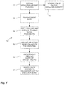
Fig. 1 is a flowchart of a method for securing a glenoid implant on a scapula, using patient specific instrumentation; -
Fig. 2 is a perspective view of a scapula with a glenoid implant, in virtual planning; -
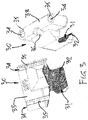
Fig. 3 is a pair of perspective views of a pin placement PSI in accordance with an embodiment of the present disclosure; -
Fig. 4 is a perspective view of the scapula with the pin placement PSI ofFig. 3 , during placement of pins; -
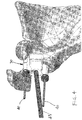
Fig. 5 is a perspective view of the scapula ofFig. 4 , during the removal of the pin placement PSI; -
Fig. 6 is a perspective view of a depth drilling PSI in accordance with another embodiment of the present disclosure; -
Fig. 7 is a perspective view of the scapula with the depth drilling PSI ofFig. 6 ; -
Fig. 8 is a perspective view of the scapula and depth drilling PSI, with a cannulated reamer; -
Fig. 9 is a perspective view of the scapula with the reamed glenoid; -
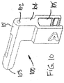
Fig. 10 is a perspective view of an impactor guide PSI in accordance with yet another embodiment of the present disclosure; -
Fig. 11 is a perspective view of the scapula with the impactor guide PSI and impactor tool; -
Fig. 12 is a perspective view of a drilling guide PSI in accordance with yet another embodiment of the present disclosure; -
Fig. 13 is a perspective view of the scapula with the drilling guide PSI and drill bit; -
Fig. 14 is an assembly view of a glenoid hemispherical implant; -
Fig. 15 is a perspective view of a scapula with a glenoid implant and a graft; and -
Fig. 16 is a lateral view of a pin placement PSI ofFig. 4 , on the scapula. - Referring to the drawings and more particularly to
Fig. 1 , there is illustrated at 10 a method for securing a glenoid implant on a scapula (i.e., scapula) In order to perform the method, patient specific instrumentation of various kinds are used, and will be referred to hereinafter as PSI, with reference toFigs. 2-13 . By way of example,Fig. 2 features the positioning of a glenoid hemispherical head implant base on the scapula, in reverse total shoulder surgery. However, themethod 10 may alternatively be used to secure a cup implant in the glenoid as performed on anatomic total shoulder replacement. - According to
step 11 ofFig. 1 , virtual shoulder surgery planning is performed. In this planning step, various shoulder structures are displayed as three-dimensional models, along with a model implant and its components. These 3-D models are typically the result of the processing preoperative imagery (e.g., CT scans, MRI, etc) and hence are a precise and accurate representation of a patient's bones. - During the planning step, the operator may select various types and dimensions of implants and interactively plan where the implant and its components will be located on the scapula and humerus. In the case of the glenoid implant, the position and orientation thereof may include a virtual representation of the position and orientation of the screws that will secure the glenoid implant to the scapula. Due to the length of the screws and the thinness of the scapula medial to the glenoid, the virtual planning of the location of the glenoid implant typically aims at finding an orientation and depth for the screws that will not have them pierce through the bone material.
- For example, there is illustrated at
Fig. 2 a model of the scapula A of the patient with parts of an implant 20 (also shown inFig. 14 ), theimplant 20 being of the ball head type (i.e., a hemispherical head 20A). Theimplant 20 comprises abase plate 21. Thebase plate 21 is of the type made of a metal that will be adhered and fitted in a resurfaced glenoid cavity C (Fig. 9 ). For instance, a trabecular-like medical grade metal may be used for thebase plate 21. Apeg 22 projects from an underside of thebase plate 21 and will be accommodated in a bore drilled in the glenoidcavity B. Screws 23 also project from the underside of thebase plate 21 and anchor theimplant 20 to the scapula A. Abody 25 is secured to thebase plate 21, as these parts are generally monolithic Thebody 25 is the interface of theimplant 20 with a hemispherical ball head that will define the surface contacting the humerus or implant thereon.Throughbores 26 are hence concurrently defined in thebody 25 andbase plate 21, with thescrews 23 passing through thesethroughbores 26. -
Steps 12 to 17 of themethod 10 are used to guide the surgeon or operator in performing bone alterations so as to replicate the virtual shoulder surgery planning ofstep 11. Hence,steps 12 to 17 themethod 10 are performed to ensure that the glenoid implant is installed substantially similarly to the virtual planning. - According to
step 12, PSI are generated using the data obtained from the virtual planning. The PSI will be described in further detail hereinafter. Any appropriate manufacturing method and materials may be used for the PSI, provided that the PSI are precise and accurate representations of the PSI required as a result of the virtual planning. The generation of PSI according to step 12 is performed preoperatively using the imagery data that is also used for thestep 11 of virtual shoulder surgery planning. Any other source of anatomical data may also be used, such as manual bone measurements, obtained pre-operatively. Another information that may be obtained via the planning step is the generation of a required graft. It may be required to use a graft wedge B1 between the implant and the scapula, and the planning step may therefore define a model of required graft, as shown inFig. 15 , as well as a PSI tool to shape the graft wedge B1 to a predetermined geometry calculated in the virtual planning. The graft wedge B1 would be positioned between theimplant 20 and the machined glenoid cavity C. The use of a graft may be required for scapulas limited to a shallow glenoid cavity C, i.e., that does not have a full counterbore shape. Hence, as shown inFig. 15 , the graft wedge B1 would form concurrently with the cavity C the surface against which theimplant 20 is applied. -
Steps 13 to 17 are performed intra-operatively. The steps are performed once the shoulder joint has been exposed and the humerus has been dislocated, resected and/or separated from the scapula A (Fig.2 ). - According to step 13 (
Fig. 1 ), a pair of pins are placed in the scapula A using PSI. Referring concurrently toFig. 3 and4 , a pin placement PSI is generally shown at 30. Thepin placement PSI 30 comprises ananatomical interface 31. Theanatomical interface 31 has a laterally opened hook-like shape so as to receive therein both sides of the scapula head and/or neck of the glenoid B. In accordance with PSI, theanatomical interface 31 has a contact surface(s) 32 that is manufactured to match the corresponding surface on the patient's scapula. Accordingly, the positioning of thepin placement PSI 30 will be guided by thecontact surface 32 finding its corresponding matching surface on the scapula A. - The
pin placement PSI 30 further comprises adrill guide 33. Thedrill guide 33 is positioned relative to theanatomical interface 31 as a function of the virtual planning of step 11 (Fig. 1 ). Thedrill guide 33 has a pair of cylindrical cutouts orslots 34 that are specifically positioned and oriented to guide the drilling of the pins in the glenoid B, i.e., theslots 34 extend in the longitudinal direction of thePSI 30. According to an embodiment,lateral openings 35 allow lateral access to theslots 34 such that the pins may be laterally inserted into theslots 34. Asocket 36 or like connector may also defined in thedrill guide 33 to facilitate the manipulation of thepin placement PSI 30. For instance, an elongated tool may be connected to thepin placement PSI 30 by way of thesocket 36, for its distal manipulation. - As shown concurrently in
Figs. 4 and5 , pins 40 are drilled into the scapula A. Thepins 40 may be provided with sleeves 41 (a.k.a., bushings) received in a planned fit (e.g., precise fit) that will ensure that thepins 40 are axially centered in theslots 34, as thesleeves 41 have throughbores centered with theslots 34. Moreover, thesleeves 41 may comprise abutment ends 42 to control the depth of insertion of thepins 40 in the glenoid. Any appropriate methods are also considered to control the depth of insertion of thepins 40, such as graduating thepins 40 with a scale, etc. - In operation, handle 43 is connected to the socket 36 (
Figs. 3 and4 ), and thepin placement PSI 30 is installed onto the glenoid B with theanatomical interface 31 ensuring that thepin placement PSI 30 is properly positioned on the scapula A, by laterally moving thepin placement PSI 30 into planned position on the bone. Thepins 40 withsleeves 41 thereon are inserted in theslots 34 of the pin placement PSI via thelateral openings 35, and may hence be drilled into the glenoid B, or the sleeves/bushings 41 may be placed in theslots 34 prior to threading thepins 40 therein. Once thepins 40 are suitably inserted in the scapula A, thesleeves 41 may be withdrawn by sliding them off the end of thepins 40 shown inFig. 5 , thereby allowing the removal of thepin placement PSI 30 from the scapula A by a lateral movement. The surfaces of the hook-like portion of theanatomical interface 31 are generally transverse to a longitudinal direction of thedrill guide 33. The presence of thelateral openings 35 allows a good contact surface between the hook-like portion of theanatomical interface 31, without having difficulties in the lateral withdrawal of thePSI 30 as thepins 40 pass through thelateral openings 35. - According to the illustrated embodiment, one of the
pins 40 is at a center of the anticipated resurfaced glenoid cavity C, while theother pin 40 is located adjacent to the superior glenoid rim in alignment with the coracoid or at the base of the coracoid. Other positions are also considered. For illustrative purposes, a contemplated position of thepin placement PSI 30 is generally shown relative to the scapula A inFig. 16 . - Referring to
Fig. 1 , astep 14 of depth drilling and/or surface reaming on the glenoid B is performed using thepins 40 and an appropriate PSI. Referring concurrently toFigs. 6 and7 , a reaming PSI is generally shown at 60. The reamingPSI 60 has afirst tube 61 with apin slot 62 that is dimensioned to be slid onto one of thepins 40, thereby forming a cylindrical joint therewith. An end of thefirst tube 61 defines anabutment 63 to abut against the scapula A. Aspacing arm 64 extends laterally from thefirst tube 61 and has at its free end asecond tube 65. Thesecond tube 65 also comprises a shaft slot 66, which shaft slot 66 is laterally accessible via alateral opening 67, used to rotate thereaming PSI 60 such that thepin 40 enters the shaft slot 66. As thereaming PSI 60 is patient specific, thepin slots 62 and the shaft slot 66 are spaced apart by a predetermined distance to match the spacing between thepins 40. Hence, as shown inFig. 7 , when thefirst tube 61 is slid onto one of thepins 40, theother pin 40 may be oriented to be within the shaft slot 66 of thesecond tube 65. - It is pointed out that
step 14 may comprise a verification of the location of thepins 40. As thereaming PSI 60 is fabricated to receive thepins 40, the centrally-locatedpin 40 should be axially centered in thesecond tube 65. Any off-centering may indicate improper positioning of thepin 40, and such indication may cause a review ofstep 13 to reposition thepins 40. - Referring to
Fig. 8 , a cannulated reamer 80 may therefore be installed onto thepin 40 that is within the shaft slot 66, so as to be coaxially guided by thepin 40 in translation. The reamer 80 has areamer end 81 that is selected to perform resurfacing of a planned diameter in the glenoid B. Thereamer end 81 is located at the end of ashaft 82. Theshaft 82 is sized to be received in the shaft slot 66 of thereaming PSI 60, to form the translational joint. Moreover, thereamer end 81 may also drill a bore of sufficient diameter to receive thepeg 22 of theimplant 20 therein (Fig. 2 ), to a depth defined by abutment against the reamingPSI 60. The drilling of the peg bore may alternatively be done separately. Accordingly, the combination of thepin 40 in the cannulated reamer 80 and the cooperation between theshaft 82 and the shaft slot 66 ensures that the glenoid B is reamed specifically where desired to a desired depth. Theshaft 82 enters the shaft slot 66 by being slid or snapped into it. Still referring toFig. 8 , astopper 83 may be installed on the end of theshaft 82. Thestopper 83 cooperates with the reamingPSI 60 to limit the depth of penetration of the reamer 80 in the glenoid B, to ensure that the surface reaming and optional depth drilling (if done separately for thepeg 22 ofFig. 2 ) have a planned depth. - It is observed that both
pins 40 are used to support thereaming PSI 60 and guide movement of the cannulated reamer 80. By using bothpins 40, the structural integrity of thepin 40/PSI 60 assembly is increased over asingle pin 40. However, it is considered to use any other configuration, for instance using asingle pin 40, with the cannulated reamer 80, the reamed the glenoid B. - As shown in
Fig. 9 , once the glenoid B has been reamed to define the resurfaced glenoid cavity C with peg bore D, thedepth drilling PSI 60 may be removed along with thepins 40. Although not shown, it may be desired to keep thepin 40 that is not in the resurfaced glenoid cavity C, as explained hereinafter. In the case in which the wedge graft B1 is used (Fig. 15 ), the wedge graft B1 is installed at the adequate position on the glenoid B, adjacent to the resurfaced glenoid cavity C. Thepin 40 on the coracoid may be used to guide an operator in properly orienting the wedge graft B1. The wedge graft B1 may be fused to the glenoid B, and thescrews 23 will secured both theimplant 20 and the wedge graft B1 to the glenoid B. - Referring to
Fig. 1 , astep 15 of impacting theimplant 20 is performed, using one of the pins and PSI for properly orienting theimplant 20. More specifically, the orientation of theimplant 20 will have an impact on the positioning of the screws 23 (Fig. 2 ). Hence, in order to replicate the virtual planning ofstep 11, theimplant 20 must be correctly oriented so as to have thethroughbores 26 aligned with the planned location of insertion of thescrews 23. - Referring concurrently to
Figs. 10 and11 , an impacting guide PSI is generally shown at 100. The impactingguide PSI 100 comprises atube 101 with apin slot 102. Thepin slot 102 is sized so as to receive therein the remainingpin 40 and form therewith a cylindrical joint. An abutment end (with any appropriate shape/geometry) 103 of the tube may have a patient-specific contact surface shaped to rest against a surrounding bone surface and hence prevent rotation of thePSI 100 when thetube 101 abuts the bone. Anarm 104 projects laterally from thetube 101. Aguide bracket 105 is at a free end of thearm 104 and is used to guide the movement of an impactor tool 110. More specifically, theguide bracket 105 has a lateral opening for receiving therein a shaft 111 of the impactor tool 110 to form a sliding joint therewith. - The impactor tool 110 may be conventional, with a pair of pegs spaced apart to be received in the
throughbores 26 of the implant 20 (Fig. 2 ). Theguide bracket 105 is specifically oriented as a function of a location of these pegs at the end of the shaft 111 of the impactor tool 110, to control the positioning of thethroughbores 26 of theimplant 20, in accordance with the virtual planning step 11 (Fig. 1 ). - Hence, with the assembly of
Fig. 11 , theimplant 20 may be inserted into the resurfaced glenoid cavity C. The matching shape of theimplant 20 and resurfaced glenoid cavity C may result in a self-centering of theimplant 20 during impacting (and therefore not necessitating the patient-specific surface at theabutment end 103 to perform an alignment). However, thePSI 100 and impactor tool 110 generally ensure that theimplant 20 is fully inserted in the resurfaced glenoid cavity C, with thethroughbores 26 located where planned. At this point, thePSI 100 may be removed with the impactor tool 110 leaving theimplant 20 in the resurfaced glenoid cavity C. - According to step 16 of
Fig. 1 , anchor holes may be drilled in the glenoid as planned, for the subsequent insertion of thescrews 23. Referring toFigs. 12 and13 , adrill guide PSI 120 has abody 121 sized to be received in a corresponding cavity in theimplant body 25. A pair of drill guide bores 122 are defined in thebody 121 of thedrill guide PSI 120. The drill guidesbores 122 are specifically located and oriented to have guidingcylinders 122A in axial extension of thethroughbores 26 in the implant 20 (Fig. 2 ). Moreover, the diameter of the guidingcylinders 122A is generally tapering to center adrill bit 123 therein, to reduce any potential play between thedrill bit 123 and the drill guide bores 122. The material used for thebody 121 of thedrill guide PSI 120 may also be selected so as not to be damaged by thedrill bit 123. As shown inFig. 13 , astopper 124 may be provided on thedrill bit 123 to control the drilling depth to reach the planned depth for the anchor holes. Alternative methods are considered as well, such as graduating thedrill bit 123 with a scale, to control the depth. Once the anchor holes have been drilled, thedrill guide PSI 120 may be removed. As shown inFig. 12 , thedrill guide PSI 120 may also comprise avisual pointer 125. Thevisual pointer 125 may be patient-specifically formed in thedrill guide PSI 120 to point at the remaining pin. This therefore represents an additional verification step to ensure that the holes are drilled at the desired location. - According to step 17 of
Fig. 1 , screws 23 (or like fasteners) may secure theimplant 20 to the scapula A, replicating the virtual planning ofFig. 2 . Conventional steps are then performed to finalize the shoulder surgery. - It is pointed out that the
method 10 may include a step of creating the graft B1 ofFig. 15 . The step ofmethod 10 may include providing a PSI tool for the removal of bone material, for instance from the humerus, as the humerus must be resurfaced. However, the graft B1 removed from the humerus or other bone may simply have a cylindrical shape, and hence a standard cylindrical reamer of appropriate diameter may be used. As the graft B1 is shown as having a wedge shape inFig. 15 , an appropriate PSI tool may be created to machine the oblique plane of the graft B1. - While the methods and systems described above have been described and shown with reference to particular steps performed in a particular order, these steps may be combined, subdivided or reordered to form an equivalent method without departing from the teachings of the present disclosure. Accordingly, the order and grouping of the steps is not a limitation of the present disclosure.
Claims (15)
- An assembly of instruments for installing an implant on a bone, the assembly of instruments comprising:a reaming instrument (60) having a first tube (61) configured to be slid onto and along a pin (40) anda reamer (80) having a reamer end (81) configured to ream the bone, characterised in that the assembly comprises a pair of pins (40) configured to be placed in known patient specific positioning relative to the bone, wherein the reaming instrument (60) includes a second tube (65) spaced from the first tube (61) to be aligned with the other of the pins(40), wherein the reamer is a cannulated reamer comprising a hollow shaft (82) supporting the reamer end (81) and configured to be driven, the hollow shaft (82) concurrently received in the second tube (65) of the reaming instrument (60) and mounted onto the other of the pins (40), for the reaming instrument (60) to guide movement of the cannulated reamer (80) when reaming the bone.
- The assembly of instruments according to claim 1, wherein the second tube (65) of the reaming instrument (60) has a lateral shaft slot (66) for receiving the hollow shaft (82) of the cannulated reamer (80).
- The assembly of instruments according to any one of claims 1 and 2, wherein the second tube (65) of the reaming instrument (60) forms an abutment at a given height from the bone, and wherein the hollow shaft (82) of the cannulated reamer (80) has a stopper (83), whereby the stopper (83) and abutment concurrently act to limit a depth of reaming.
- The assembly of instruments according to any one of claims 1 to 3, wherein the first tube (61) and the second tube (65) of the reaming instrument (60) are parallel to one another.
- The assembly of instruments according to any one of claims 1 to 4, with a first of the pins (40) configured to be placed in a planned glenoid implant center, and the second of the pins (40) configured to be located away from the glenoid.
- The assembly of instruments according to any one of claims 1 to 5, wherein the reamer end (81) is sized as a function of a planned glenoid implant size.
- The assembly of instruments according to any one of claims 1 to 6, further comprising an impacting guide (100) having a guide tube (101) configured to be slid onto one of the pins (40) to be slid along the pin (40) after removal of the reaming instrument (40) after reaming, and a guide bracket (105) spaced from the guide tube (101) to be aligned with a reamed surface of the bone, the guide bracket (105) configured to receive a shaft (111) of an impactor tool (110).
- The assembly of instruments according to claim 7, wherein the guide bracket (105) has a lateral opening configured to receive the shaft (111) of the impactor tool (110) .
- The assembly of instruments according to any one of claims 7 and 8, wherein the guide tube (101) has an abutment end (103) configured to contact the bone to prevent rotation of the impacting guide (100) relative to the bone and pin (40) .
- The assembly of instruments according to claim 9, wherein the abutment end (103) has at least one patient specific surface based on an anatomical model of the patient.
- The assembly of instruments according to any one of claims 7 to 10, further comprising the impactor tool (110), the impactor tool (110) having the shaft (111) for guidingly engaging the guide bracket (105), and an end for supporting an implant.
- The assembly of instruments according to any one of claims 1 to 11, further comprising a pin placement instrument (30) for placing the pins (4), the pin placement instrument (30) comprising an anatomical interface (31) with a hook-like portion being opened in a lateral direction of the instrument (30) to receive a bone therein in a planned position, a drill guide (33) connected to the anatomical interface (31) and defining guide slots (34) in a longitudinal direction of the instrument, the guide slots (34) each having a lateral opening (35) over its full length in the drill guide (33) to allow lateral withdrawal of the instrument (30) in said lateral direction with the pin (40) placed in the bone passing through the lateral opening (35), and a bushing (41) removably placed in each said guide slot (33) via said longitudinal direction in a planned fit, the bushings (41) defining a throughbore aligned with the guide slot (34) and adapted to receive the pin (40) extending in said longitudinal direction when the bushing (41) is in the guide slot (34) for pin placement.
- The assembly of instruments according to claim 12, wherein the anatomical interface (31) with a hook-like portion has at least one patient specific surface (32) based on an anatomical model of the patient.
- The assembly of instruments according to any one of claims 1 to 13, wherein one of the pins 40 is configured to be longitudinally aligned with a planned center of an implant in a glenoid, and the other of the pins 40 is configured to be located adjacent to the superior glenoid rim in alignment with the coracoid or at a base of the coracoid.
- The assembly of instruments according to any one of claims 1 to 14, further including the glenoid implant (20).
Applications Claiming Priority (5)
| Application Number | Priority Date | Filing Date | Title |
|---|---|---|---|
| US201261616623P | 2012-03-28 | 2012-03-28 | |
| US201261659272P | 2012-06-13 | 2012-06-13 | |
| US201261675955P | 2012-07-26 | 2012-07-26 | |
| EP13768750.5A EP2830521B1 (en) | 2012-03-28 | 2013-03-28 | Glenoid implant surgery using patient specific instrumentation |
| PCT/CA2013/050253 WO2013142998A1 (en) | 2012-03-28 | 2013-03-28 | Glenoid implant surgery using patient specific instrumentation |
Related Parent Applications (2)
| Application Number | Title | Priority Date | Filing Date |
|---|---|---|---|
| EP13768750.5A Division EP2830521B1 (en) | 2012-03-28 | 2013-03-28 | Glenoid implant surgery using patient specific instrumentation |
| EP13768750.5A Division-Into EP2830521B1 (en) | 2012-03-28 | 2013-03-28 | Glenoid implant surgery using patient specific instrumentation |
Publications (2)
| Publication Number | Publication Date |
|---|---|
| EP3251620A1 EP3251620A1 (en) | 2017-12-06 |
| EP3251620B1 true EP3251620B1 (en) | 2021-04-14 |
Family
ID=49258018
Family Applications (2)
| Application Number | Title | Priority Date | Filing Date |
|---|---|---|---|
| EP13768750.5A Active EP2830521B1 (en) | 2012-03-28 | 2013-03-28 | Glenoid implant surgery using patient specific instrumentation |
| EP17178147.9A Active EP3251620B1 (en) | 2012-03-28 | 2013-03-28 | Glenoid implant surgery using patient specific instrument |
Family Applications Before (1)
| Application Number | Title | Priority Date | Filing Date |
|---|---|---|---|
| EP13768750.5A Active EP2830521B1 (en) | 2012-03-28 | 2013-03-28 | Glenoid implant surgery using patient specific instrumentation |
Country Status (7)
| Country | Link |
|---|---|
| US (3) | US10543100B2 (en) |
| EP (2) | EP2830521B1 (en) |
| JP (3) | JP6166775B2 (en) |
| CN (1) | CN104203134B (en) |
| CA (3) | CA3072704C (en) |
| ES (1) | ES2637823T3 (en) |
| WO (1) | WO2013142998A1 (en) |
Families Citing this family (63)
| Publication number | Priority date | Publication date | Assignee | Title |
|---|---|---|---|---|
| US8388624B2 (en) | 2003-02-24 | 2013-03-05 | Arthrosurface Incorporated | Trochlear resurfacing system and method |
| JP2008504107A (en) | 2004-06-28 | 2008-02-14 | アースロサーフィス・インコーポレーテッド | Joint surface replacement system |
| AU2007332787A1 (en) | 2006-12-11 | 2008-06-19 | Arthrosurface Incorporated | Retrograde resection apparatus and method |
| FR2932674B1 (en) | 2008-06-20 | 2011-11-18 | Tornier Sa | METHOD FOR MODELING A GLENOIDAL SURFACE OF AN OMOPLATE, DEVICE FOR IMPLANTING A GLENOIDAL COMPONENT OF A SHOULDER PROSTHESIS, AND METHOD FOR MANUFACTURING SUCH COMPOUND |
| GB0819635D0 (en) * | 2008-10-27 | 2008-12-03 | Auron Invest Ltd | A composition for the treatment of hypertension |
| WO2010121250A1 (en) | 2009-04-17 | 2010-10-21 | Arthrosurface Incorporated | Glenoid resurfacing system and method |
| US10945743B2 (en) | 2009-04-17 | 2021-03-16 | Arthrosurface Incorporated | Glenoid repair system and methods of use thereof |
| FR2955247B1 (en) | 2010-01-21 | 2013-04-26 | Tornier Sa | GLENOIDAL COMPONENT OF SHOULDER PROSTHESIS |
| BR112012022482A2 (en) | 2010-03-05 | 2016-07-19 | Arthrosurface Inc | tibial surface recomposition system and method. |
| FR2971144A1 (en) | 2011-02-08 | 2012-08-10 | Tornier Sa | GLENOIDAL IMPLANT FOR SHOULDER PROSTHESIS AND SURGICAL KIT |
| ES2635542T3 (en) | 2011-10-27 | 2017-10-04 | Biomet Manufacturing, Llc | Glenoid guides specific to the patient |
| US9301812B2 (en) | 2011-10-27 | 2016-04-05 | Biomet Manufacturing, Llc | Methods for patient-specific shoulder arthroplasty |
| US9451973B2 (en) | 2011-10-27 | 2016-09-27 | Biomet Manufacturing, Llc | Patient specific glenoid guide |
| EP2804565B1 (en) | 2011-12-22 | 2018-03-07 | Arthrosurface Incorporated | System for bone fixation |
| DE112013003358T5 (en) | 2012-07-03 | 2015-03-19 | Arthrosurface, Inc. | System and procedure for joint surface replacement and repair |
| US9839438B2 (en) * | 2013-03-11 | 2017-12-12 | Biomet Manufacturing, Llc | Patient-specific glenoid guide with a reusable guide holder |
| US9492200B2 (en) | 2013-04-16 | 2016-11-15 | Arthrosurface Incorporated | Suture system and method |
| US9173665B2 (en) * | 2013-09-06 | 2015-11-03 | Zimmer, Inc. | Patient-specific surgical guide for intra-operative production of patient-specific augment |
| EP3628245B1 (en) * | 2013-10-10 | 2025-01-29 | Stryker European Operations Limited | Method for designing and producing a shoulder surgery guide |
| WO2015056097A1 (en) * | 2013-10-17 | 2015-04-23 | Imascap | Methods, systems and devices for pre-operatively planned glenoid placement guides and uses thereof |
| WO2015068035A1 (en) | 2013-11-08 | 2015-05-14 | Imascap | Methods, systems and devices for pre-operatively planned adaptive glenoid implants |
| EP3068317B1 (en) | 2013-11-13 | 2018-08-22 | Tornier | Shoulder patient specific instrument |
| EP3777777B1 (en) | 2014-01-03 | 2023-04-05 | Howmedica Osteonics Corp. | Glenoid implant for a shoulder prosthesis |
| US11607319B2 (en) | 2014-03-07 | 2023-03-21 | Arthrosurface Incorporated | System and method for repairing articular surfaces |
| US10624748B2 (en) | 2014-03-07 | 2020-04-21 | Arthrosurface Incorporated | System and method for repairing articular surfaces |
| US9931219B2 (en) | 2014-03-07 | 2018-04-03 | Arthrosurface Incorporated | Implant and anchor assembly |
| US10575968B2 (en) | 2014-05-16 | 2020-03-03 | Howmedica Osteonics Corp. | Guides for fracture system |
| US9681960B2 (en) | 2014-05-16 | 2017-06-20 | Howmedica Osteonics Corp. | Guides for fracture system |
| US10070873B2 (en) | 2014-06-30 | 2018-09-11 | Tornier, Inc. | Device for maintaining alignment of a cannulated shaft over a guide pin |
| US10806472B2 (en) * | 2015-03-10 | 2020-10-20 | Smith & Nephew, Inc. | Open Latarjet for correction of anterior-inferior glenoid bone loss |
| GB201504122D0 (en) * | 2015-03-11 | 2015-04-22 | Imp Innovations Ltd | Patient-specific surgical guide |
| ES3026762T3 (en) * | 2015-03-24 | 2025-06-12 | Arthrosurface Inc | Glenoid repair system |
| CA2979426A1 (en) | 2015-03-25 | 2016-09-29 | Orthosoft Ulc | Glenosphere-implant positioning device and method |
| CN107405169B (en) * | 2015-03-25 | 2021-01-26 | 奥尔索夫特无限责任公司 | System for assisting implant placement in thin bone such as scapula |
| EP3291768B1 (en) * | 2015-04-24 | 2019-11-27 | Biomet Manufacturing, LLC | Patient-specific augmented glenoid systems |
| US10722374B2 (en) | 2015-05-05 | 2020-07-28 | Tornier, Inc. | Convertible glenoid implant |
| WO2016191725A1 (en) * | 2015-05-28 | 2016-12-01 | Zimmer, Inc. | Patient-specific bone grafting system and method |
| US10426624B2 (en) | 2015-06-02 | 2019-10-01 | Zimmer, Inc. | Glenosphere guide tool |
| CN107847204B (en) * | 2015-07-08 | 2022-06-07 | 捷迈有限公司 | Patient specific instrumentation for implant revision surgery |
| WO2017105815A1 (en) | 2015-12-16 | 2017-06-22 | Tornier, Inc. | Patient specific instruments and methods for joint prosthesis |
| EP3685804A1 (en) | 2016-03-25 | 2020-07-29 | Tornier | Joint prosthesis spacer |
| EP3481318B1 (en) | 2016-07-08 | 2022-09-14 | Biomet Manufacturing, LLC | Reverse shoulder pre-operative planning |
| US9737313B1 (en) | 2016-11-07 | 2017-08-22 | Roger C. Sohn | Shoulder reamer devices, systems including the same, and related methods |
| EP3624737B1 (en) * | 2017-05-19 | 2021-08-04 | Biomet Manufacturing, LLC | Implant assembly tools |
| EP3651662B1 (en) | 2017-07-11 | 2025-07-02 | Howmedica Osteonics Corp. | Patient specific humeral cutting guides |
| US11234721B2 (en) | 2017-07-11 | 2022-02-01 | Howmedica Osteonics Corp. | Guides and instruments for improving accuracy of glenoid implant placement |
| CA3108761A1 (en) | 2017-08-04 | 2019-02-07 | Arthrosurface Incorporated | Multicomponent articular surface implant |
| EP4497417B1 (en) | 2017-10-16 | 2026-04-29 | Stryker European Operations Limited | Shoulder implants |
| EP3727167B1 (en) * | 2017-12-22 | 2025-09-24 | Medacta International SA | Cutting guide for periacetabular osteotomy and kit for periacetabular osteotomy |
| EP3731783A1 (en) | 2017-12-29 | 2020-11-04 | Tornier, Inc. | Patient specific humeral implant components |
| EP3833277A1 (en) * | 2018-08-10 | 2021-06-16 | Tornier, Inc. | Guides and instruments for improving accuracy of glenoid implant placement |
| CN111493972B (en) * | 2019-01-30 | 2024-07-12 | 北京大学第三医院(北京大学第三临床医学院) | Bone drill sighting device |
| GB2609338B (en) | 2019-03-12 | 2023-06-14 | Arthrosurface Inc | Humeral and glenoid articular surface implant systems and methods |
| AU2020276186C1 (en) | 2019-05-13 | 2022-07-21 | Howmedica Osteonics Corp. | Glenoid baseplate and implant assemblies |
| US12303207B2 (en) | 2019-05-20 | 2025-05-20 | Howmedica Osteonics Corp. | Automated planning of shoulder stability enhancement surgeries |
| US20220265290A1 (en) | 2019-08-09 | 2022-08-25 | Howmedica Osteonics Corp. | Apparatuses and methods for implanting glenoid prostheses |
| CN112315581B (en) * | 2020-09-29 | 2022-05-06 | 上海霖晏医疗科技有限公司 | A method and device for determining the entry point of a pedicle screw |
| JP7620116B2 (en) | 2021-02-26 | 2025-01-22 | ハウメディカ オステオニクス コーポレイション | Glenoid implant components and instruments thereof |
| WO2023008942A1 (en) * | 2021-07-29 | 2023-02-02 | 애니메디솔루션 주식회사 | Pin guide and screw guide for surgery of artificial shoulder joint |
| KR102624485B1 (en) * | 2023-07-12 | 2024-01-15 | (주)시안솔루션 | Method for designing patient-specific guidance, program and server thereof |
| US12591216B1 (en) | 2024-02-02 | 2026-03-31 | Restor3D, Inc. | Patient-specific medical devices based on bone density and processes for producing the same |
| CN118873233B (en) * | 2024-08-27 | 2025-01-28 | 常州市妇幼保健院 | Clavicle and coracoid bone tunnel alignment and wire passing device |
| US12605251B1 (en) | 2025-03-28 | 2026-04-21 | Restor3D, Inc. | Patient-specific shoulder implants and processes for producing and using the same |
Family Cites Families (192)
| Publication number | Priority date | Publication date | Assignee | Title |
|---|---|---|---|---|
| US4841975A (en) | 1987-04-15 | 1989-06-27 | Cemax, Inc. | Preoperative planning of bone cuts and joint replacement using radiant energy scan imaging |
| US5030219A (en) | 1990-01-22 | 1991-07-09 | Boehringer Mannheim Corporation | Glenoid component installation tools |
| US5098383A (en) | 1990-02-08 | 1992-03-24 | Artifax Ltd. | Device for orienting appliances, prostheses, and instrumentation in medical procedures and methods of making same |
| EP0630212B1 (en) | 1992-02-20 | 1998-07-08 | Synvasive Technology, Inc. | Surgical cutting block |
| US5342369A (en) * | 1992-09-11 | 1994-08-30 | The Board Of Regents Of The University Of Washington | System for repair of bankart lesions |
| US5354300A (en) * | 1993-01-15 | 1994-10-11 | Depuy Inc. | Drill guide apparatus for installing a transverse pin |
| US5330468A (en) * | 1993-10-12 | 1994-07-19 | Burkhart Stephen S | Drill guide device for arthroscopic surgery |
| BE1008372A3 (en) | 1994-04-19 | 1996-04-02 | Materialise Nv | METHOD FOR MANUFACTURING A perfected MEDICAL MODEL BASED ON DIGITAL IMAGE INFORMATION OF A BODY. |
| US5489310A (en) * | 1994-06-27 | 1996-02-06 | Mikhail; W. E. Michael | Universal glenoid shoulder prosthesis and method for implanting |
| US5682886A (en) | 1995-12-26 | 1997-11-04 | Musculographics Inc | Computer-assisted surgical system |
| US5769856A (en) | 1996-06-24 | 1998-06-23 | Osteonics Corp. | Drill guide and implant method |
| US8083745B2 (en) | 2001-05-25 | 2011-12-27 | Conformis, Inc. | Surgical tools for arthroplasty |
| US8771365B2 (en) | 2009-02-25 | 2014-07-08 | Conformis, Inc. | Patient-adapted and improved orthopedic implants, designs, and related tools |
| US8882847B2 (en) | 2001-05-25 | 2014-11-11 | Conformis, Inc. | Patient selectable knee joint arthroplasty devices |
| US7468075B2 (en) | 2001-05-25 | 2008-12-23 | Conformis, Inc. | Methods and compositions for articular repair |
| US8480754B2 (en) | 2001-05-25 | 2013-07-09 | Conformis, Inc. | Patient-adapted and improved articular implants, designs and related guide tools |
| US20090222103A1 (en) | 2001-05-25 | 2009-09-03 | Conformis, Inc. | Articular Implants Providing Lower Adjacent Cartilage Wear |
| US7799077B2 (en) | 2002-10-07 | 2010-09-21 | Conformis, Inc. | Minimally invasive joint implant with 3-dimensional geometry matching the articular surfaces |
| US20110071802A1 (en) | 2009-02-25 | 2011-03-24 | Ray Bojarski | Patient-adapted and improved articular implants, designs and related guide tools |
| US8735773B2 (en) | 2007-02-14 | 2014-05-27 | Conformis, Inc. | Implant device and method for manufacture |
| US8617242B2 (en) | 2001-05-25 | 2013-12-31 | Conformis, Inc. | Implant device and method for manufacture |
| US9603711B2 (en) | 2001-05-25 | 2017-03-28 | Conformis, Inc. | Patient-adapted and improved articular implants, designs and related guide tools |
| US7534263B2 (en) | 2001-05-25 | 2009-05-19 | Conformis, Inc. | Surgical tools facilitating increased accuracy, speed and simplicity in performing joint arthroplasty |
| US8545569B2 (en) | 2001-05-25 | 2013-10-01 | Conformis, Inc. | Patient selectable knee arthroplasty devices |
| US20110071645A1 (en) | 2009-02-25 | 2011-03-24 | Ray Bojarski | Patient-adapted and improved articular implants, designs and related guide tools |
| US8556983B2 (en) | 2001-05-25 | 2013-10-15 | Conformis, Inc. | Patient-adapted and improved orthopedic implants, designs and related tools |
| US7618451B2 (en) | 2001-05-25 | 2009-11-17 | Conformis, Inc. | Patient selectable joint arthroplasty devices and surgical tools facilitating increased accuracy, speed and simplicity in performing total and partial joint arthroplasty |
| US20070233269A1 (en) | 2001-05-25 | 2007-10-04 | Conformis, Inc. | Interpositional Joint Implant |
| US5916219A (en) | 1997-02-10 | 1999-06-29 | Matsuno; Shigeo | Tibial plateau resection guide |
| US6379386B1 (en) * | 1997-09-09 | 2002-04-30 | Stryker Technologies Corporation | Anatomic glenoid shoulder prosthesis together with methods and tools for implanting same |
| US6428541B1 (en) * | 1998-04-09 | 2002-08-06 | Sdgi Holdings, Inc. | Method and instrumentation for vertebral interbody fusion |
| ES2228037T3 (en) | 1998-04-09 | 2005-04-01 | Sdgi Holdings, Inc. | VERTEBRAL BODY SEPARATOR DEVICE. |
| US7635390B1 (en) | 2000-01-14 | 2009-12-22 | Marctec, Llc | Joint replacement component having a modular articulating surface |
| US8439926B2 (en) | 2001-05-25 | 2013-05-14 | Conformis, Inc. | Patient selectable joint arthroplasty devices and surgical tools |
| AU2007202573A1 (en) | 2001-05-25 | 2007-06-28 | Conformis, Inc. | Methods and compositions for articular resurfacing |
| JP2005504563A (en) | 2001-05-25 | 2005-02-17 | イメージング セラピューティクス,インコーポレーテッド | Methods and compositions for resurfacing joints |
| US20070156171A1 (en) | 2001-05-25 | 2007-07-05 | Conformis, Inc. | Implant Grasper |
| US20130211531A1 (en) | 2001-05-25 | 2013-08-15 | Conformis, Inc. | Patient-adapted and improved articular implants, designs and related guide tools |
| WO2013155501A1 (en) | 2012-04-13 | 2013-10-17 | Conformis, Inc. | Patient adapted joint arthroplasty devices, surgical tools and methods of use |
| US6364910B1 (en) * | 2001-07-11 | 2002-04-02 | Biomet, Inc. | Method and apparatus for use of a glenoid component |
| US8801720B2 (en) | 2002-05-15 | 2014-08-12 | Otismed Corporation | Total joint arthroplasty system |
| US8965075B2 (en) | 2002-09-16 | 2015-02-24 | Imatx, Inc. | System and method for predicting future fractures |
| CN1728976A (en) | 2002-10-07 | 2006-02-01 | 康复米斯公司 | Minimally invasive joint implant with 3-dimensional geometry matching the articular surfaces |
| WO2004043305A1 (en) | 2002-11-07 | 2004-05-27 | Conformis, Inc. | Methods for determing meniscal size and shape and for devising treatment |
| CA2506849A1 (en) | 2002-12-04 | 2004-06-17 | Konstantinos Tsougarakis | Fusion of multiple imaging planes for isotropic imaging in mri and quantitative image analysis using isotropic or near-isotropic imaging |
| US7201756B2 (en) * | 2003-03-24 | 2007-04-10 | Herbert Earl Ross | Device and method to assist in arthroscopic repair of detached connective tissue |
| WO2005016123A2 (en) * | 2003-08-11 | 2005-02-24 | Chudik Steven C M D | Devices and methods used for shoulder replacement |
| AU2011203237B2 (en) | 2003-11-25 | 2012-06-14 | Conformis, Inc. | Patient selectable knee joint arthroplasty devices |
| US8175683B2 (en) | 2003-12-30 | 2012-05-08 | Depuy Products, Inc. | System and method of designing and manufacturing customized instrumentation for accurate implantation of prosthesis by utilizing computed tomography data |
| US20060079963A1 (en) * | 2004-10-07 | 2006-04-13 | Regan Hansen | Semiconstrained shoulder prosthetic for treatment of rotator cuff arthropathy |
| US20060111722A1 (en) | 2004-11-19 | 2006-05-25 | Hacene Bouadi | Surgical cutting tool |
| CA2623834A1 (en) | 2005-09-30 | 2007-04-12 | Conformis, Inc. | Joint arthroplasty devices |
| CN101384230A (en) | 2005-11-21 | 2009-03-11 | 福特真公司 | Devices and methods for treating facet, uncinate, costovertebral, and other joints |
| US7357057B2 (en) | 2006-01-06 | 2008-04-15 | Tung-Lung Chiang | Paper cutter |
| US7854768B2 (en) * | 2006-01-20 | 2010-12-21 | Zimmer Technology, Inc. | Shoulder arthroplasty system |
| EP2649951A3 (en) | 2006-02-06 | 2013-12-25 | ConforMIS, Inc. | Patient selectable joint arthroplasty devices and surgical tools |
| US8623026B2 (en) | 2006-02-06 | 2014-01-07 | Conformis, Inc. | Patient selectable joint arthroplasty devices and surgical tools incorporating anatomical relief |
| US8500740B2 (en) | 2006-02-06 | 2013-08-06 | Conformis, Inc. | Patient-specific joint arthroplasty devices for ligament repair |
| CA2642615A1 (en) | 2006-02-15 | 2007-08-30 | Otismed Corp | Arthroplasty jigs and related methods |
| US9808262B2 (en) | 2006-02-15 | 2017-11-07 | Howmedica Osteonics Corporation | Arthroplasty devices and related methods |
| US8070752B2 (en) | 2006-02-27 | 2011-12-06 | Biomet Manufacturing Corp. | Patient specific alignment guide and inter-operative adjustment |
| US8858561B2 (en) | 2006-06-09 | 2014-10-14 | Blomet Manufacturing, LLC | Patient-specific alignment guide |
| US9173661B2 (en) | 2006-02-27 | 2015-11-03 | Biomet Manufacturing, Llc | Patient specific alignment guide with cutting surface and laser indicator |
| US9113971B2 (en) | 2006-02-27 | 2015-08-25 | Biomet Manufacturing, Llc | Femoral acetabular impingement guide |
| US8603180B2 (en) | 2006-02-27 | 2013-12-10 | Biomet Manufacturing, Llc | Patient-specific acetabular alignment guides |
| US8377066B2 (en) | 2006-02-27 | 2013-02-19 | Biomet Manufacturing Corp. | Patient-specific elbow guides and associated methods |
| US8092465B2 (en) | 2006-06-09 | 2012-01-10 | Biomet Manufacturing Corp. | Patient specific knee alignment guide and associated method |
| US8282646B2 (en) | 2006-02-27 | 2012-10-09 | Biomet Manufacturing Corp. | Patient specific knee alignment guide and associated method |
| US20110172672A1 (en) | 2006-02-27 | 2011-07-14 | Biomet Manufacturing Corp. | Instrument with transparent portion for use with patient-specific alignment guide |
| US8241293B2 (en) | 2006-02-27 | 2012-08-14 | Biomet Manufacturing Corp. | Patient specific high tibia osteotomy |
| US9339278B2 (en) | 2006-02-27 | 2016-05-17 | Biomet Manufacturing, Llc | Patient-specific acetabular guides and associated instruments |
| US9289253B2 (en) | 2006-02-27 | 2016-03-22 | Biomet Manufacturing, Llc | Patient-specific shoulder guide |
| US8608749B2 (en) | 2006-02-27 | 2013-12-17 | Biomet Manufacturing, Llc | Patient-specific acetabular guides and associated instruments |
| US8591516B2 (en) | 2006-02-27 | 2013-11-26 | Biomet Manufacturing, Llc | Patient-specific orthopedic instruments |
| US7967868B2 (en) | 2007-04-17 | 2011-06-28 | Biomet Manufacturing Corp. | Patient-modified implant and associated method |
| US8864769B2 (en) | 2006-02-27 | 2014-10-21 | Biomet Manufacturing, Llc | Alignment guides with patient-specific anchoring elements |
| US8608748B2 (en) | 2006-02-27 | 2013-12-17 | Biomet Manufacturing, Llc | Patient specific guides |
| US10278711B2 (en) | 2006-02-27 | 2019-05-07 | Biomet Manufacturing, Llc | Patient-specific femoral guide |
| US8133234B2 (en) | 2006-02-27 | 2012-03-13 | Biomet Manufacturing Corp. | Patient specific acetabular guide and method |
| US8298237B2 (en) | 2006-06-09 | 2012-10-30 | Biomet Manufacturing Corp. | Patient-specific alignment guide for multiple incisions |
| US8535387B2 (en) | 2006-02-27 | 2013-09-17 | Biomet Manufacturing, Llc | Patient-specific tools and implants |
| CA2646288A1 (en) | 2006-03-21 | 2007-09-27 | Conformis, Inc. | Interpositional joint implant |
| US8460302B2 (en) | 2006-12-18 | 2013-06-11 | Otismed Corporation | Arthroplasty devices and related methods |
| WO2008112996A1 (en) | 2007-03-14 | 2008-09-18 | Conformis, Inc. | Surgical tools for arthroplasty |
| GB2447702A (en) | 2007-03-23 | 2008-09-24 | Univ Leeds | Surgical bone cutting template |
| EP2157926B1 (en) | 2007-05-14 | 2015-04-22 | Queen's University At Kingston | Patient-specific surgical guidance tool |
| WO2008157412A2 (en) | 2007-06-13 | 2008-12-24 | Conformis, Inc. | Surgical cutting guide |
| GB0712290D0 (en) | 2007-06-25 | 2007-08-01 | Depuy Orthopaedie Gmbh | Surgical instrument |
| EP2957243A1 (en) | 2007-09-30 | 2015-12-23 | DePuy Products, Inc. | Customized patient-specific orthopaedic surgical instrumentation |
| US8460303B2 (en) | 2007-10-25 | 2013-06-11 | Otismed Corporation | Arthroplasty systems and devices, and related methods |
| ATE527949T1 (en) * | 2007-11-02 | 2011-10-15 | Depuy Products Inc | FIXATION SYSTEM FOR ELBOW Fracture |
| US10582934B2 (en) | 2007-11-27 | 2020-03-10 | Howmedica Osteonics Corporation | Generating MRI images usable for the creation of 3D bone models employed to make customized arthroplasty jigs |
| US8737700B2 (en) | 2007-12-18 | 2014-05-27 | Otismed Corporation | Preoperatively planning an arthroplasty procedure and generating a corresponding patient specific arthroplasty resection guide |
| US8617171B2 (en) | 2007-12-18 | 2013-12-31 | Otismed Corporation | Preoperatively planning an arthroplasty procedure and generating a corresponding patient specific arthroplasty resection guide |
| US8777875B2 (en) | 2008-07-23 | 2014-07-15 | Otismed Corporation | System and method for manufacturing arthroplasty jigs having improved mating accuracy |
| US8715291B2 (en) | 2007-12-18 | 2014-05-06 | Otismed Corporation | Arthroplasty system and related methods |
| US8160345B2 (en) | 2008-04-30 | 2012-04-17 | Otismed Corporation | System and method for image segmentation in generating computer models of a joint to undergo arthroplasty |
| US8545509B2 (en) | 2007-12-18 | 2013-10-01 | Otismed Corporation | Arthroplasty system and related methods |
| US8221430B2 (en) | 2007-12-18 | 2012-07-17 | Otismed Corporation | System and method for manufacturing arthroplasty jigs |
| US8480679B2 (en) | 2008-04-29 | 2013-07-09 | Otismed Corporation | Generation of a computerized bone model representative of a pre-degenerated state and useable in the design and manufacture of arthroplasty devices |
| GB0803514D0 (en) | 2008-02-27 | 2008-04-02 | Depuy Int Ltd | Customised surgical apparatus |
| US8734455B2 (en) | 2008-02-29 | 2014-05-27 | Otismed Corporation | Hip resurfacing surgical guide tool |
| CN104382630B (en) | 2008-03-03 | 2017-04-12 | 史密夫和内修有限公司 | Low profile patient specific cutting blocks for a knee joint |
| WO2009111481A1 (en) * | 2008-03-03 | 2009-09-11 | Arthrosurface Incorporated | Bone resurfacing system and method |
| WO2009111626A2 (en) | 2008-03-05 | 2009-09-11 | Conformis, Inc. | Implants for altering wear patterns of articular surfaces |
| WO2009111639A1 (en) | 2008-03-05 | 2009-09-11 | Conformis, Inc. | Patient selectable joint arthroplasty devices and surgical tools |
| WO2009111656A1 (en) | 2008-03-05 | 2009-09-11 | Conformis, Inc. | Edge-matched articular implant |
| JP2011519713A (en) | 2008-05-12 | 2011-07-14 | コンフォーミス・インコーポレイテッド | Devices and methods for treatment of facet joints and other joints |
| CN201227321Y (en) * | 2008-06-27 | 2009-04-29 | 魏朋建 | Simple steel-wire fixation conductor |
| US8617175B2 (en) | 2008-12-16 | 2013-12-31 | Otismed Corporation | Unicompartmental customized arthroplasty cutting jigs and methods of making the same |
| US8078440B2 (en) | 2008-09-19 | 2011-12-13 | Smith & Nephew, Inc. | Operatively tuning implants for increased performance |
| US8992538B2 (en) | 2008-09-30 | 2015-03-31 | DePuy Synthes Products, Inc. | Customized patient-specific acetabular orthopaedic surgical instrument and method of use and fabrication |
| US20100185202A1 (en) | 2009-01-16 | 2010-07-22 | Lester Mark B | Customized patient-specific patella resectioning guide |
| US20100217399A1 (en) * | 2009-02-22 | 2010-08-26 | Groh Gordon I | Base plate system for shoulder arthroplasty and method of using the same |
| US9017334B2 (en) | 2009-02-24 | 2015-04-28 | Microport Orthopedics Holdings Inc. | Patient specific surgical guide locator and mount |
| EP2405865B1 (en) | 2009-02-24 | 2019-04-17 | ConforMIS, Inc. | Automated systems for manufacturing patient-specific orthopedic implants and instrumentation |
| US20100217270A1 (en) | 2009-02-25 | 2010-08-26 | Conformis, Inc. | Integrated Production of Patient-Specific Implants and Instrumentation |
| CN102405032B (en) | 2009-02-25 | 2016-08-03 | 康复米斯公司 | Orthopaedic implants, design and the related tool that patient adapts to and improves |
| US8337503B2 (en) | 2009-04-13 | 2012-12-25 | George John Lian | Custom radiographically designed cutting guides and instruments for use in total ankle replacement surgery |
| US9561041B2 (en) | 2009-05-07 | 2017-02-07 | Smith & Nephew, Inc. | Patient specific alignment guide for a proximal femur |
| US8449552B2 (en) * | 2009-06-04 | 2013-05-28 | Quantum Surgical | Surgical drill guide with awl and method of use |
| EP2442757B1 (en) | 2009-06-17 | 2017-03-01 | Universität Bern | Methods and devices for patient-specific acetabular component alignment in total hip arthroplasty |
| RU2011149966A (en) | 2009-06-24 | 2013-07-27 | Кастом Мед Ортопэдикс (Проприетери) Лимитед | GUIDE DEVICE AND ORIENTATION SYSTEM FOR FEMORAL OPERATION |
| US8414591B2 (en) | 2009-07-17 | 2013-04-09 | Materialise N.V. | Surgical guiding tool, methods for manufacture and uses thereof |
| CN201453365U (en) * | 2009-07-31 | 2010-05-12 | 张英泽 | Acromioclavicular joint fixation guider |
| US8702717B2 (en) * | 2009-07-31 | 2014-04-22 | Zimmer Gmbh | Glenoid alignment tool |
| DE102009028503B4 (en) | 2009-08-13 | 2013-11-14 | Biomet Manufacturing Corp. | Resection template for the resection of bones, method for producing such a resection template and operation set for performing knee joint surgery |
| US8876830B2 (en) | 2009-08-13 | 2014-11-04 | Zimmer, Inc. | Virtual implant placement in the OR |
| SG178836A1 (en) | 2009-08-26 | 2012-04-27 | Conformis Inc | Patient-specific orthopedic implants and models |
| BR112012005527A2 (en) | 2009-09-10 | 2016-04-26 | Blue Ortho | alignment guide for use in computer aided orthopedic surgery to prepare a bone element for an implant |
| CA2778057C (en) | 2009-10-29 | 2019-02-19 | Zimmer, Inc. | Patient-specific mill guide |
| EP2496183B1 (en) | 2009-11-04 | 2015-09-02 | ConforMIS, Inc. | Patient-adapted and improved orthopedic implants, designs and related tools |
| MX2012005649A (en) | 2009-11-17 | 2012-12-05 | Univ Kingston | Patient-specific guide for acetabular cup placement. |
| EP2509539B1 (en) | 2009-12-11 | 2020-07-01 | ConforMIS, Inc. | Patient-specific and patient-engineered orthopedic implants |
| WO2011075697A2 (en) | 2009-12-18 | 2011-06-23 | Conformis, Inc. | Patient-adapted and improved orthopedic implants, designs and related tools |
| US8506569B2 (en) * | 2009-12-31 | 2013-08-13 | DePuy Synthes Products, LLC | Reciprocating rasps for use in an orthopaedic surgical procedure |
| US8556901B2 (en) * | 2009-12-31 | 2013-10-15 | DePuy Synthes Products, LLC | Reciprocating rasps for use in an orthopaedic surgical procedure |
| US8632547B2 (en) | 2010-02-26 | 2014-01-21 | Biomet Sports Medicine, Llc | Patient-specific osteotomy devices and methods |
| US9066727B2 (en) | 2010-03-04 | 2015-06-30 | Materialise Nv | Patient-specific computed tomography guides |
| GB201003921D0 (en) | 2010-03-10 | 2010-04-21 | Depuy Orthopaedie Gmbh | Orthopaedic instrument |
| US9579106B2 (en) | 2010-03-31 | 2017-02-28 | New York Society For The Relief Of The Ruptured And Crippled, Maintaining The Hospital For Special Surgery | Shoulder arthroplasty instrumentation |
| AU2011265254B2 (en) | 2010-06-11 | 2016-05-19 | Smith & Nephew, Inc. | Patient-matched instruments |
| US8974535B2 (en) | 2010-06-11 | 2015-03-10 | Sunnybrook Health Sciences Centre | Method of forming patient-specific implant |
| EP2582328B1 (en) | 2010-06-18 | 2017-09-13 | Howmedica Osteonics Corp. | Patient-specific total hip arthroplasty |
| US8808302B2 (en) | 2010-08-12 | 2014-08-19 | DePuy Synthes Products, LLC | Customized patient-specific acetabular orthopaedic surgical instrument and method of use and fabrication |
| KR20130137157A (en) * | 2010-08-16 | 2013-12-16 | 스미스 앤드 네퓨, 인크. | Patient-matched tissue guide for placing a surgical device |
| CN103338714B (en) | 2010-09-07 | 2015-11-25 | 克里夫兰诊所基金会 | Positioning devices for prosthetic implants |
| US8617170B2 (en) | 2010-09-29 | 2013-12-31 | DePuy Synthes Products, LLC | Customized patient-specific computer controlled cutting system and method |
| US9271744B2 (en) | 2010-09-29 | 2016-03-01 | Biomet Manufacturing, Llc | Patient-specific guide for partial acetabular socket replacement |
| WO2012058355A1 (en) | 2010-10-29 | 2012-05-03 | The Cleveland Clinic Foundation | System of preoperative planning and provision of patient-specific surgical aids |
| US20120276509A1 (en) | 2010-10-29 | 2012-11-01 | The Cleveland Clinic Foundation | System of preoperative planning and provision of patient-specific surgical aids |
| CA2816337C (en) * | 2010-10-29 | 2019-10-22 | The Cleveland Clinic Foundation | System and method for association of a guiding aid with a patient tissue |
| FR2967047B1 (en) * | 2010-11-05 | 2013-09-20 | Aston Medical | JIG FOR INSTALLING A SHOULDER PROSTHESIS ON A GLEN |
| BE1019572A5 (en) | 2010-11-10 | 2012-08-07 | Materialise Nv | OPTIMIZED METHODS FOR THE PRODUCTION OF PATIENT-SPECIFIC MEDICAL TOOLS. |
| CA2817207A1 (en) | 2010-11-11 | 2012-05-18 | Zimmer, Inc. | Patient-specific instruments for total hip arthroplasty |
| US8486076B2 (en) * | 2011-01-28 | 2013-07-16 | DePuy Synthes Products, LLC | Oscillating rasp for use in an orthopaedic surgical procedure |
| EP2754419B1 (en) | 2011-02-15 | 2024-02-07 | ConforMIS, Inc. | Patient-adapted and improved orthopedic implants |
| US9186154B2 (en) | 2011-03-17 | 2015-11-17 | Zimmer, Inc. | Patient-specific instruments for total ankle arthroplasty |
| US9820758B2 (en) | 2011-03-18 | 2017-11-21 | DePuy Synthes Products, Inc. | Combination reamer/drill bit for shoulder arthoplasty |
| US9226830B2 (en) * | 2011-03-18 | 2016-01-05 | DePuy Synthes Products, Inc. | Device and method for retroversion correction for shoulder arthroplasty |
| US8715289B2 (en) | 2011-04-15 | 2014-05-06 | Biomet Manufacturing, Llc | Patient-specific numerically controlled instrument |
| US9675400B2 (en) | 2011-04-19 | 2017-06-13 | Biomet Manufacturing, Llc | Patient-specific fracture fixation instrumentation and method |
| US8668700B2 (en) | 2011-04-29 | 2014-03-11 | Biomet Manufacturing, Llc | Patient-specific convertible guides |
| US20140142578A1 (en) * | 2011-07-12 | 2014-05-22 | Materialise N.V. | Surgical instrument for the positioning of an alignment element |
| EP2739251A4 (en) | 2011-08-03 | 2015-07-29 | Conformis Inc | Automated design, selection, manufacturing and implantation of patient-adapted and improved articular implants, designs and related guide tools |
| SG11201400064YA (en) | 2011-08-15 | 2014-09-26 | Conformis Inc | Revision systems, tools and methods for revising joint arthroplasty implants |
| EP2757978B1 (en) | 2011-09-21 | 2016-08-17 | Materialise N.V. | Patient-specific surgical guide |
| EP2765955B1 (en) | 2011-10-14 | 2019-11-20 | ConforMIS, Inc. | Methods and systems for identification, assessment, modeling, and repair of anatomical disparities in joint replacement |
| US9451973B2 (en) * | 2011-10-27 | 2016-09-27 | Biomet Manufacturing, Llc | Patient specific glenoid guide |
| KR20130046336A (en) * | 2011-10-27 | 2013-05-07 | 삼성전자주식회사 | Multi-view device of display apparatus and contol method thereof, and display system |
| ES3037161T3 (en) | 2011-10-28 | 2025-09-29 | Mat Nv | Shoulder guides |
| EP2670314B1 (en) | 2011-10-28 | 2014-08-13 | Materialise N.V. | Shoulder base plate coverage and stability |
| US20130184713A1 (en) | 2011-12-23 | 2013-07-18 | Conformis, Inc. | Anatomical Alignment Systems and Methods |
| US20130211410A1 (en) | 2012-02-07 | 2013-08-15 | Conformis, Inc. | Patella Resection Instrument Guide Having Optional Patient-Specific Features |
| WO2013119790A1 (en) | 2012-02-07 | 2013-08-15 | Conformis, Inc. | Tibial implant devices, systems, and methods |
| WO2013119865A1 (en) | 2012-02-07 | 2013-08-15 | Conformis Inc | Joint arthroplasty devices, systems, and methods |
| WO2013131066A1 (en) | 2012-03-02 | 2013-09-06 | Conformis, Inc. | Patient-adapted posterior stabilized knee implants, designs and related methods and tools |
| HK1204908A1 (en) | 2012-04-06 | 2015-12-11 | Conformis, Inc. | Advanced methods, techniques, devices, and systems for cruciate retaining knee implants |
| RU2579623C1 (en) | 2012-04-13 | 2016-04-10 | Конформис, Инк. | Devices and methods for additive manufacturing of implant components |
| US9486226B2 (en) | 2012-04-18 | 2016-11-08 | Conformis, Inc. | Tibial guides, tools, and techniques for resecting the tibial plateau |
| US20130289570A1 (en) | 2012-04-27 | 2013-10-31 | Conformis, Inc. | Tibial Template and Punch System, Tools and Methods for Preparing the Tibia |
| US20130297031A1 (en) | 2012-05-02 | 2013-11-07 | Conformis, Inc. | Patient specific instruments and related methods for joint replacement |
| US9675471B2 (en) | 2012-06-11 | 2017-06-13 | Conformis, Inc. | Devices, techniques and methods for assessing joint spacing, balancing soft tissues and obtaining desired kinematics for joint implant components |
| WO2014008444A1 (en) | 2012-07-03 | 2014-01-09 | Conformis, Inc. | Devices, systems, and methods for impacting joint implant components |
| US20150223941A1 (en) | 2012-08-27 | 2015-08-13 | Conformis, Inc. | Methods, Devices and Techniques for Improved Placement and Fixation of Shoulder Implant Components |
| CN104780872B (en) | 2012-09-21 | 2017-04-05 | 康复米斯公司 | The method and system of the design and manufacture of optimization implant component is manufactured using free entity |
| US9320527B2 (en) * | 2013-01-18 | 2016-04-26 | Biomet Manufacturing, Llc | Quick-connect anti-rotation peg/drill bit component |
| US9839438B2 (en) * | 2013-03-11 | 2017-12-12 | Biomet Manufacturing, Llc | Patient-specific glenoid guide with a reusable guide holder |
| US9044330B2 (en) * | 2013-03-12 | 2015-06-02 | DePuy Synthes Products, Inc. | System and method for implanting a secondary glenoid prosthesis |
| US10010431B2 (en) * | 2013-03-27 | 2018-07-03 | Materialise N.V. | Customized surgical guide |
| US9615839B2 (en) * | 2014-03-18 | 2017-04-11 | Howmedica Osteonics Corp. | Shape-fit glenoid reaming systems and methods |
| EP3651662B1 (en) * | 2017-07-11 | 2025-07-02 | Howmedica Osteonics Corp. | Patient specific humeral cutting guides |
-
2013
- 2013-03-28 CA CA3072704A patent/CA3072704C/en active Active
- 2013-03-28 ES ES13768750.5T patent/ES2637823T3/en active Active
- 2013-03-28 CN CN201380016223.0A patent/CN104203134B/en active Active
- 2013-03-28 EP EP13768750.5A patent/EP2830521B1/en active Active
- 2013-03-28 EP EP17178147.9A patent/EP3251620B1/en active Active
- 2013-03-28 CA CA3072716A patent/CA3072716C/en active Active
- 2013-03-28 US US14/386,620 patent/US10543100B2/en active Active
- 2013-03-28 CA CA2866395A patent/CA2866395C/en active Active
- 2013-03-28 WO PCT/CA2013/050253 patent/WO2013142998A1/en not_active Ceased
- 2013-03-28 JP JP2015502026A patent/JP6166775B2/en active Active
-
2017
- 2017-06-22 JP JP2017122421A patent/JP6483758B2/en active Active
-
2019
- 2019-02-14 JP JP2019024550A patent/JP2019084381A/en active Pending
-
2020
- 2020-01-07 US US16/736,122 patent/US11432934B2/en active Active
-
2022
- 2022-08-03 US US17/880,302 patent/US12599486B2/en active Active
Non-Patent Citations (1)
| Title |
|---|
| None * |
Also Published As
| Publication number | Publication date |
|---|---|
| EP2830521A1 (en) | 2015-02-04 |
| US20150073424A1 (en) | 2015-03-12 |
| CN104203134B (en) | 2017-06-20 |
| CA2866395A1 (en) | 2013-10-03 |
| CA2866395C (en) | 2020-11-10 |
| JP2015511511A (en) | 2015-04-20 |
| JP2017159151A (en) | 2017-09-14 |
| CA3072704C (en) | 2022-03-22 |
| CA3072716C (en) | 2022-03-22 |
| CA3072716A1 (en) | 2013-10-03 |
| CN104203134A (en) | 2014-12-10 |
| US20230061695A1 (en) | 2023-03-02 |
| US10543100B2 (en) | 2020-01-28 |
| US20200138586A1 (en) | 2020-05-07 |
| US12599486B2 (en) | 2026-04-14 |
| WO2013142998A1 (en) | 2013-10-03 |
| EP2830521A4 (en) | 2015-11-25 |
| JP6166775B2 (en) | 2017-07-19 |
| EP2830521B1 (en) | 2017-08-02 |
| EP3251620A1 (en) | 2017-12-06 |
| US11432934B2 (en) | 2022-09-06 |
| CA3072704A1 (en) | 2013-10-03 |
| JP2019084381A (en) | 2019-06-06 |
| JP6483758B2 (en) | 2019-03-13 |
| ES2637823T3 (en) | 2017-10-17 |
Similar Documents
| Publication | Publication Date | Title |
|---|---|---|
| US12599486B2 (en) | Glenoid implant surgery using patient specific instrumentation | |
| US11020128B2 (en) | Patient-specific bone grafting system and method | |
| AU2014249415B2 (en) | Patient-specific glenoid guide with a reusable guide holder | |
| US10426493B2 (en) | Patient-specific glenoid guides | |
| EP2770918B1 (en) | Patient-specific glenoid guides | |
| US9211128B2 (en) | Devices and methods for hip replacement | |
| US9125702B2 (en) | Acetabular drill pin | |
| CN110623775A (en) | Tibial Prosthesis Rotational Alignment Device | |
| WO2021026029A1 (en) | Shoulder reaming guide with checking feature |
Legal Events
| Date | Code | Title | Description |
|---|---|---|---|
| PUAI | Public reference made under article 153(3) epc to a published international application that has entered the european phase |
Free format text: ORIGINAL CODE: 0009012 |
|
| STAA | Information on the status of an ep patent application or granted ep patent |
Free format text: STATUS: THE APPLICATION HAS BEEN PUBLISHED |
|
| AC | Divisional application: reference to earlier application |
Ref document number: 2830521 Country of ref document: EP Kind code of ref document: P |
|
| AK | Designated contracting states |
Kind code of ref document: A1 Designated state(s): AL AT BE BG CH CY CZ DE DK EE ES FI FR GB GR HR HU IE IS IT LI LT LU LV MC MK MT NL NO PL PT RO RS SE SI SK SM TR |
|
| STAA | Information on the status of an ep patent application or granted ep patent |
Free format text: STATUS: REQUEST FOR EXAMINATION WAS MADE |
|
| STAA | Information on the status of an ep patent application or granted ep patent |
Free format text: STATUS: EXAMINATION IS IN PROGRESS |
|
| 17P | Request for examination filed |
Effective date: 20180606 |
|
| RBV | Designated contracting states (corrected) |
Designated state(s): AL AT BE BG CH CY CZ DE DK EE ES FI FR GB GR HR HU IE IS IT LI LT LU LV MC MK MT NL NO PL PT RO RS SE SI SK SM TR |
|
| 17Q | First examination report despatched |
Effective date: 20180711 |
|
| RAP1 | Party data changed (applicant data changed or rights of an application transferred) |
Owner name: ORTHOSOFT ULC |
|
| GRAP | Despatch of communication of intention to grant a patent |
Free format text: ORIGINAL CODE: EPIDOSNIGR1 |
|
| STAA | Information on the status of an ep patent application or granted ep patent |
Free format text: STATUS: GRANT OF PATENT IS INTENDED |
|
| INTG | Intention to grant announced |
Effective date: 20201009 |
|
| GRAS | Grant fee paid |
Free format text: ORIGINAL CODE: EPIDOSNIGR3 |
|
| GRAA | (expected) grant |
Free format text: ORIGINAL CODE: 0009210 |
|
| STAA | Information on the status of an ep patent application or granted ep patent |
Free format text: STATUS: THE PATENT HAS BEEN GRANTED |
|
| AC | Divisional application: reference to earlier application |
Ref document number: 2830521 Country of ref document: EP Kind code of ref document: P |
|
| AK | Designated contracting states |
Kind code of ref document: B1 Designated state(s): AL AT BE BG CH CY CZ DE DK EE ES FI FR GB GR HR HU IE IS IT LI LT LU LV MC MK MT NL NO PL PT RO RS SE SI SK SM TR |
|
| REG | Reference to a national code |
Ref country code: GB Ref legal event code: FG4D |
|
| REG | Reference to a national code |
Ref country code: CH Ref legal event code: EP |
|
| REG | Reference to a national code |
Ref country code: DE Ref legal event code: R096 Ref document number: 602013076951 Country of ref document: DE |
|
| REG | Reference to a national code |
Ref country code: IE Ref legal event code: FG4D |
|
| REG | Reference to a national code |
Ref country code: AT Ref legal event code: REF Ref document number: 1381573 Country of ref document: AT Kind code of ref document: T Effective date: 20210515 |
|
| REG | Reference to a national code |
Ref country code: LT Ref legal event code: MG9D |
|
| REG | Reference to a national code |
Ref country code: AT Ref legal event code: MK05 Ref document number: 1381573 Country of ref document: AT Kind code of ref document: T Effective date: 20210414 |
|
| REG | Reference to a national code |
Ref country code: NL Ref legal event code: MP Effective date: 20210414 |
|
| PG25 | Lapsed in a contracting state [announced via postgrant information from national office to epo] |
Ref country code: FI Free format text: LAPSE BECAUSE OF FAILURE TO SUBMIT A TRANSLATION OF THE DESCRIPTION OR TO PAY THE FEE WITHIN THE PRESCRIBED TIME-LIMIT Effective date: 20210414 Ref country code: LT Free format text: LAPSE BECAUSE OF FAILURE TO SUBMIT A TRANSLATION OF THE DESCRIPTION OR TO PAY THE FEE WITHIN THE PRESCRIBED TIME-LIMIT Effective date: 20210414 Ref country code: NL Free format text: LAPSE BECAUSE OF FAILURE TO SUBMIT A TRANSLATION OF THE DESCRIPTION OR TO PAY THE FEE WITHIN THE PRESCRIBED TIME-LIMIT Effective date: 20210414 Ref country code: HR Free format text: LAPSE BECAUSE OF FAILURE TO SUBMIT A TRANSLATION OF THE DESCRIPTION OR TO PAY THE FEE WITHIN THE PRESCRIBED TIME-LIMIT Effective date: 20210414 Ref country code: AT Free format text: LAPSE BECAUSE OF FAILURE TO SUBMIT A TRANSLATION OF THE DESCRIPTION OR TO PAY THE FEE WITHIN THE PRESCRIBED TIME-LIMIT Effective date: 20210414 Ref country code: BG Free format text: LAPSE BECAUSE OF FAILURE TO SUBMIT A TRANSLATION OF THE DESCRIPTION OR TO PAY THE FEE WITHIN THE PRESCRIBED TIME-LIMIT Effective date: 20210714 |
|
| PG25 | Lapsed in a contracting state [announced via postgrant information from national office to epo] |
Ref country code: NO Free format text: LAPSE BECAUSE OF FAILURE TO SUBMIT A TRANSLATION OF THE DESCRIPTION OR TO PAY THE FEE WITHIN THE PRESCRIBED TIME-LIMIT Effective date: 20210714 Ref country code: PT Free format text: LAPSE BECAUSE OF FAILURE TO SUBMIT A TRANSLATION OF THE DESCRIPTION OR TO PAY THE FEE WITHIN THE PRESCRIBED TIME-LIMIT Effective date: 20210816 Ref country code: PL Free format text: LAPSE BECAUSE OF FAILURE TO SUBMIT A TRANSLATION OF THE DESCRIPTION OR TO PAY THE FEE WITHIN THE PRESCRIBED TIME-LIMIT Effective date: 20210414 Ref country code: RS Free format text: LAPSE BECAUSE OF FAILURE TO SUBMIT A TRANSLATION OF THE DESCRIPTION OR TO PAY THE FEE WITHIN THE PRESCRIBED TIME-LIMIT Effective date: 20210414 Ref country code: SE Free format text: LAPSE BECAUSE OF FAILURE TO SUBMIT A TRANSLATION OF THE DESCRIPTION OR TO PAY THE FEE WITHIN THE PRESCRIBED TIME-LIMIT Effective date: 20210414 Ref country code: LV Free format text: LAPSE BECAUSE OF FAILURE TO SUBMIT A TRANSLATION OF THE DESCRIPTION OR TO PAY THE FEE WITHIN THE PRESCRIBED TIME-LIMIT Effective date: 20210414 Ref country code: IS Free format text: LAPSE BECAUSE OF FAILURE TO SUBMIT A TRANSLATION OF THE DESCRIPTION OR TO PAY THE FEE WITHIN THE PRESCRIBED TIME-LIMIT Effective date: 20210814 Ref country code: GR Free format text: LAPSE BECAUSE OF FAILURE TO SUBMIT A TRANSLATION OF THE DESCRIPTION OR TO PAY THE FEE WITHIN THE PRESCRIBED TIME-LIMIT Effective date: 20210715 |
|
| REG | Reference to a national code |
Ref country code: DE Ref legal event code: R097 Ref document number: 602013076951 Country of ref document: DE |
|
| PG25 | Lapsed in a contracting state [announced via postgrant information from national office to epo] |
Ref country code: RO Free format text: LAPSE BECAUSE OF FAILURE TO SUBMIT A TRANSLATION OF THE DESCRIPTION OR TO PAY THE FEE WITHIN THE PRESCRIBED TIME-LIMIT Effective date: 20210414 Ref country code: ES Free format text: LAPSE BECAUSE OF FAILURE TO SUBMIT A TRANSLATION OF THE DESCRIPTION OR TO PAY THE FEE WITHIN THE PRESCRIBED TIME-LIMIT Effective date: 20210414 Ref country code: EE Free format text: LAPSE BECAUSE OF FAILURE TO SUBMIT A TRANSLATION OF THE DESCRIPTION OR TO PAY THE FEE WITHIN THE PRESCRIBED TIME-LIMIT Effective date: 20210414 Ref country code: CZ Free format text: LAPSE BECAUSE OF FAILURE TO SUBMIT A TRANSLATION OF THE DESCRIPTION OR TO PAY THE FEE WITHIN THE PRESCRIBED TIME-LIMIT Effective date: 20210414 Ref country code: DK Free format text: LAPSE BECAUSE OF FAILURE TO SUBMIT A TRANSLATION OF THE DESCRIPTION OR TO PAY THE FEE WITHIN THE PRESCRIBED TIME-LIMIT Effective date: 20210414 Ref country code: SM Free format text: LAPSE BECAUSE OF FAILURE TO SUBMIT A TRANSLATION OF THE DESCRIPTION OR TO PAY THE FEE WITHIN THE PRESCRIBED TIME-LIMIT Effective date: 20210414 Ref country code: SK Free format text: LAPSE BECAUSE OF FAILURE TO SUBMIT A TRANSLATION OF THE DESCRIPTION OR TO PAY THE FEE WITHIN THE PRESCRIBED TIME-LIMIT Effective date: 20210414 |
|
| PLBE | No opposition filed within time limit |
Free format text: ORIGINAL CODE: 0009261 |
|
| STAA | Information on the status of an ep patent application or granted ep patent |
Free format text: STATUS: NO OPPOSITION FILED WITHIN TIME LIMIT |
|
| 26N | No opposition filed |
Effective date: 20220117 |
|
| PGFP | Annual fee paid to national office [announced via postgrant information from national office to epo] |
Ref country code: CH Payment date: 20220215 Year of fee payment: 10 |
|
| PG25 | Lapsed in a contracting state [announced via postgrant information from national office to epo] |
Ref country code: IS Free format text: LAPSE BECAUSE OF FAILURE TO SUBMIT A TRANSLATION OF THE DESCRIPTION OR TO PAY THE FEE WITHIN THE PRESCRIBED TIME-LIMIT Effective date: 20210814 Ref country code: AL Free format text: LAPSE BECAUSE OF FAILURE TO SUBMIT A TRANSLATION OF THE DESCRIPTION OR TO PAY THE FEE WITHIN THE PRESCRIBED TIME-LIMIT Effective date: 20210414 |
|
| PG25 | Lapsed in a contracting state [announced via postgrant information from national office to epo] |
Ref country code: IT Free format text: LAPSE BECAUSE OF FAILURE TO SUBMIT A TRANSLATION OF THE DESCRIPTION OR TO PAY THE FEE WITHIN THE PRESCRIBED TIME-LIMIT Effective date: 20210414 |
|
| PG25 | Lapsed in a contracting state [announced via postgrant information from national office to epo] |
Ref country code: MC Free format text: LAPSE BECAUSE OF FAILURE TO SUBMIT A TRANSLATION OF THE DESCRIPTION OR TO PAY THE FEE WITHIN THE PRESCRIBED TIME-LIMIT Effective date: 20210414 |
|
| REG | Reference to a national code |
Ref country code: BE Ref legal event code: MM Effective date: 20220331 |
|
| PG25 | Lapsed in a contracting state [announced via postgrant information from national office to epo] |
Ref country code: LU Free format text: LAPSE BECAUSE OF NON-PAYMENT OF DUE FEES Effective date: 20220328 Ref country code: IE Free format text: LAPSE BECAUSE OF NON-PAYMENT OF DUE FEES Effective date: 20220328 |
|
| PG25 | Lapsed in a contracting state [announced via postgrant information from national office to epo] |
Ref country code: BE Free format text: LAPSE BECAUSE OF NON-PAYMENT OF DUE FEES Effective date: 20220331 |
|
| P01 | Opt-out of the competence of the unified patent court (upc) registered |
Effective date: 20230526 |
|
| REG | Reference to a national code |
Ref country code: CH Ref legal event code: PL |
|
| PG25 | Lapsed in a contracting state [announced via postgrant information from national office to epo] |
Ref country code: LI Free format text: LAPSE BECAUSE OF NON-PAYMENT OF DUE FEES Effective date: 20230331 Ref country code: CH Free format text: LAPSE BECAUSE OF NON-PAYMENT OF DUE FEES Effective date: 20230331 |
|
| PG25 | Lapsed in a contracting state [announced via postgrant information from national office to epo] |
Ref country code: HU Free format text: LAPSE BECAUSE OF FAILURE TO SUBMIT A TRANSLATION OF THE DESCRIPTION OR TO PAY THE FEE WITHIN THE PRESCRIBED TIME-LIMIT; INVALID AB INITIO Effective date: 20130328 |
|
| PG25 | Lapsed in a contracting state [announced via postgrant information from national office to epo] |
Ref country code: MK Free format text: LAPSE BECAUSE OF FAILURE TO SUBMIT A TRANSLATION OF THE DESCRIPTION OR TO PAY THE FEE WITHIN THE PRESCRIBED TIME-LIMIT Effective date: 20210414 Ref country code: CY Free format text: LAPSE BECAUSE OF FAILURE TO SUBMIT A TRANSLATION OF THE DESCRIPTION OR TO PAY THE FEE WITHIN THE PRESCRIBED TIME-LIMIT Effective date: 20210414 |
|
| PG25 | Lapsed in a contracting state [announced via postgrant information from national office to epo] |
Ref country code: MT Free format text: LAPSE BECAUSE OF FAILURE TO SUBMIT A TRANSLATION OF THE DESCRIPTION OR TO PAY THE FEE WITHIN THE PRESCRIBED TIME-LIMIT Effective date: 20210414 |
|
| PG25 | Lapsed in a contracting state [announced via postgrant information from national office to epo] |
Ref country code: TR Free format text: LAPSE BECAUSE OF FAILURE TO SUBMIT A TRANSLATION OF THE DESCRIPTION OR TO PAY THE FEE WITHIN THE PRESCRIBED TIME-LIMIT Effective date: 20210414 |
|
| PGFP | Annual fee paid to national office [announced via postgrant information from national office to epo] |
Ref country code: GB Payment date: 20260213 Year of fee payment: 14 |
|
| PGFP | Annual fee paid to national office [announced via postgrant information from national office to epo] |
Ref country code: DE Payment date: 20260216 Year of fee payment: 14 |
|
| PGFP | Annual fee paid to national office [announced via postgrant information from national office to epo] |
Ref country code: FR Payment date: 20260212 Year of fee payment: 14 |