EP3251484A1 - Procede et dispositif destines au fonctionnement d'une machine agricole - Google Patents
Procede et dispositif destines au fonctionnement d'une machine agricole Download PDFInfo
- Publication number
- EP3251484A1 EP3251484A1 EP16172934.8A EP16172934A EP3251484A1 EP 3251484 A1 EP3251484 A1 EP 3251484A1 EP 16172934 A EP16172934 A EP 16172934A EP 3251484 A1 EP3251484 A1 EP 3251484A1
- Authority
- EP
- European Patent Office
- Prior art keywords
- field area
- implements
- lowered
- working
- processed
- Prior art date
- Legal status (The legal status is an assumption and is not a legal conclusion. Google has not performed a legal analysis and makes no representation as to the accuracy of the status listed.)
- Granted
Links
Images


Classifications
-
- A—HUMAN NECESSITIES
- A01—AGRICULTURE; FORESTRY; ANIMAL HUSBANDRY; HUNTING; TRAPPING; FISHING
- A01B—SOIL WORKING IN AGRICULTURE OR FORESTRY; PARTS, DETAILS, OR ACCESSORIES OF AGRICULTURAL MACHINES OR IMPLEMENTS, IN GENERAL
- A01B63/00—Lifting or adjusting devices or arrangements for agricultural machines or implements
- A01B63/002—Devices for adjusting or regulating the position of tools or wheels
- A01B63/008—Vertical adjustment of tools
-
- A—HUMAN NECESSITIES
- A01—AGRICULTURE; FORESTRY; ANIMAL HUSBANDRY; HUNTING; TRAPPING; FISHING
- A01B—SOIL WORKING IN AGRICULTURE OR FORESTRY; PARTS, DETAILS, OR ACCESSORIES OF AGRICULTURAL MACHINES OR IMPLEMENTS, IN GENERAL
- A01B69/00—Steering of agricultural machines or implements; Guiding agricultural machines or implements on a desired track
- A01B69/003—Steering or guiding of machines or implements pushed or pulled by or mounted on agricultural vehicles such as tractors, e.g. by lateral shifting of the towing connection
- A01B69/004—Steering or guiding of machines or implements pushed or pulled by or mounted on agricultural vehicles such as tractors, e.g. by lateral shifting of the towing connection automatic
-
- A—HUMAN NECESSITIES
- A01—AGRICULTURE; FORESTRY; ANIMAL HUSBANDRY; HUNTING; TRAPPING; FISHING
- A01B—SOIL WORKING IN AGRICULTURE OR FORESTRY; PARTS, DETAILS, OR ACCESSORIES OF AGRICULTURAL MACHINES OR IMPLEMENTS, IN GENERAL
- A01B63/00—Lifting or adjusting devices or arrangements for agricultural machines or implements
- A01B63/02—Lifting or adjusting devices or arrangements for agricultural machines or implements for implements mounted on tractors
-
- A—HUMAN NECESSITIES
- A01—AGRICULTURE; FORESTRY; ANIMAL HUSBANDRY; HUNTING; TRAPPING; FISHING
- A01B—SOIL WORKING IN AGRICULTURE OR FORESTRY; PARTS, DETAILS, OR ACCESSORIES OF AGRICULTURAL MACHINES OR IMPLEMENTS, IN GENERAL
- A01B63/00—Lifting or adjusting devices or arrangements for agricultural machines or implements
- A01B63/14—Lifting or adjusting devices or arrangements for agricultural machines or implements for implements drawn by animals or tractors
- A01B63/24—Tools or tool-holders adjustable relatively to the frame
- A01B63/28—Tools or tool-holders adjustable relatively to the frame operated by the machine or implement
-
- A—HUMAN NECESSITIES
- A01—AGRICULTURE; FORESTRY; ANIMAL HUSBANDRY; HUNTING; TRAPPING; FISHING
- A01B—SOIL WORKING IN AGRICULTURE OR FORESTRY; PARTS, DETAILS, OR ACCESSORIES OF AGRICULTURAL MACHINES OR IMPLEMENTS, IN GENERAL
- A01B79/00—Methods for working soil
- A01B79/005—Precision agriculture
-
- A—HUMAN NECESSITIES
- A01—AGRICULTURE; FORESTRY; ANIMAL HUSBANDRY; HUNTING; TRAPPING; FISHING
- A01D—HARVESTING; MOWING
- A01D34/00—Mowers; Mowing apparatus of harvesters
- A01D34/006—Control or measuring arrangements
-
- A—HUMAN NECESSITIES
- A01—AGRICULTURE; FORESTRY; ANIMAL HUSBANDRY; HUNTING; TRAPPING; FISHING
- A01D—HARVESTING; MOWING
- A01D78/00—Haymakers with tines moving with respect to the machine
- A01D78/08—Haymakers with tines moving with respect to the machine with tine-carrying rotary heads or wheels
- A01D78/10—Haymakers with tines moving with respect to the machine with tine-carrying rotary heads or wheels the tines rotating about a substantially vertical axis
- A01D78/1028—Pivotable rotor support arms
-
- A—HUMAN NECESSITIES
- A01—AGRICULTURE; FORESTRY; ANIMAL HUSBANDRY; HUNTING; TRAPPING; FISHING
- A01D—HARVESTING; MOWING
- A01D78/00—Haymakers with tines moving with respect to the machine
- A01D78/08—Haymakers with tines moving with respect to the machine with tine-carrying rotary heads or wheels
- A01D78/10—Haymakers with tines moving with respect to the machine with tine-carrying rotary heads or wheels the tines rotating about a substantially vertical axis
- A01D78/1085—Having two rows of rotors on two different horizontal lines perpendicular to the advance direction of the machine
Definitions
- the invention relates to a method for operating an agricultural machine having the features of the preamble of claim 1, an agricultural machine having the features of the preamble of claim 13 and a machine control for an agricultural machine having the features of the preamble of claim 14.
- the crop for example, grass
- an agricultural machine by a combination of equipment in the form of a mower and / or rake.
- the crop is first mowed and then stored by the rake as a swath on the agricultural land, before it is taken, for example, with a self-loading wagon and transported away.
- the agricultural machine consisting of a towing vehicle and an associated implement combination in the form of mower or rake is used, which comprises a support frame with several transverse to the direction of travel or on the towing vehicle front or rear side arranged tools.
- Such tools can be, for example, cutter bar and / or rotary rake.
- the rotary rakes are each formed from a gyroscope head and a plurality of tine arms arranged circumferentially thereof, from the ends of each of which a plurality of tines protrude toward the bottom. Due to the rotational movement of the rotary rake distributed over the agricultural land crop is matched to the windrow.
- the implements are each independently raised and lowered to bring them either in a headland position or in engagement with the crop. This makes it possible either to lower the implements for processing or to raise in an already processed field area, for example in the headlands, in the headland position, so that the swath already stored there is not affected.
- a hay harvesting device is known in which two harvesting processing tools are automatically brought into the headland position or in engagement with the crop depending on the device speed and an angle between the direction of travel and a boundary line.
- the boundary line is either detected by a camera or taken from the field map of a GPS system.
- a disadvantage of the known device is that the real situation on the agricultural land does not always match exactly enough with the existing field map of the GPS system. This leads to inaccurate processing and corresponding crop failures.
- the object of the present invention is therefore to provide a method and a device for operating an agricultural machine with a towing vehicle and a working device combination connected to the towing vehicle in the form of a mower and / or rake, in which there are lower crop losses.
- the invention provides a method for operating an agricultural machine with the features of claim 1 ready.
- the method can run in a machine control for the agricultural machine as a computer program.
- the towing vehicle may be a tractor or a tractor.
- the towing vehicle comprises a vehicle frame on which a motor is arranged with a gearbox through which a plurality of wheels are driven for the movement of the implement combination.
- the towing vehicle may include a cab for an operator in which a plurality of controls for controlling the towing vehicle and / or the implement combination are arranged.
- the tractor may have steered wheels, preferably with manual a steering wheel in the cabin and / or steerable automatically by means of the machine control.
- the machine control can be arranged in the towing vehicle.
- the towing vehicle may have a hitch for attaching a rear implement combination and a PTO for transmitting a drive force to the implement combination.
- the implements can be brought into a rotational movement for processing the crop, for example, to collapse by means of rotary rakes or mowing with mowing discs.
- the towing vehicle may include control lines to the implement combination to raise and / or lower the implements.
- the direction of travel of the implement combination may be that direction in which the implement combination is moved by the towing vehicle during processing.
- the fact that the implement combination is "connected" to the towing vehicle may mean here that the implement combination is attached to the towing vehicle. Likewise, this may mean that the implement combination front, rear and / or side is connected via the hitch to the towing vehicle.
- the implement combination may be a mower for mowing and / or a rake for collapsing the crop.
- the implements may be mowing discs, mowing bars on which mowing discs are preferably arranged and / or rotary gyros.
- processing the crop here may be meant the mowing and / or collapse of the crop.
- the work equipment combination in the form of a mower may include as a work equipment side, front and / or rear mower.
- the side, front and / or rear mower can each be a cutter bar, which protrude from the towing vehicle frontally, laterally or rearward.
- two cutter bars may be arranged laterally projecting from the tractor.
- the mowing discs may rotate about their respective axis for mowing the crop and / or have circumferentially disposed cutting edges.
- the support frame of the mower may be arranged at the front, sides and / or rear of the towing vehicle, preferably via the hitch.
- the support frame may consist of several separate units, which are arranged in each case via individual towing devices front, side and / or rear of the towing vehicle and which are connected to each other via the towing vehicle.
- the mower may additionally have swathing devices to deposit the crop directly after mowing with the mower discs in a swath on the agricultural land.
- rotary rakes can be arranged in pairs on the rake, the rotary rakes rotating in a pair opposite, so that the crop is placed between the two as a swath or a cascading, a subsequent, closer pair of rotary rake.
- a first pair rotary rake with a wider span which feeds the crop to a subsequent second pair raking rotor with a smaller span.
- the second pair of rotary rakes then lay the crop in a swath on the agricultural area.
- the rotary gyros may each comprise a rotatable gyroscope head with circumferentially arranged tine arms, from the outer ends of which in each case a plurality of tines protrude toward the ground and are engaged with the crop. It is also conceivable that the rake more rotary rake are arranged, which are not automatically raised or lowered.
- the support frame may extend in the rake substantially along the direction of travel and / or be supported with wheels on the agricultural area.
- the implement combination may include the support frame on which the implements are arranged transversely to the direction of travel.
- the fact that "the implements of the support frame are arranged transversely to the direction of travel of the implement combination" in a front, side and / or rear mower means that a cutter bar is arranged transversely to the direction of travel.
- To raise and lower the implements can be connected via traversable and / or swivel arms with the support frame. It is conceivable that the implements are transversely movable in addition to the arrival and departure at a distance from the support frame, for example, to set the working width of the combination of implements.
- length-adjustable arms are provided on the support frame.
- the arms can be adjusted by hydraulic drives.
- the arms may each be arranged projecting transversely to the support frame substantially in the direction of travel.
- the implement combination can be connected via control lines, such as hydraulic lines, with the towing vehicle to raise or lower the work tools, for example by means of hydraulic cylinders.
- control lines such as hydraulic lines
- the fact that the "working devices can each be raised and lowered independently of one another" can mean here that the movement of the working devices can be individually raised and lowered by means of the pivotable arms by control lines from the towing vehicle and / or from the machine control.
- the "headland position” can be a raised position of the implements, which is taken in the so-called headland and in which the combination of implements in the Machining the agricultural area is turned.
- the implements can be lowered when engaging with the crop in a working position, in particular where the mower discs of the mower deck and / or the cutter bar of the mower and / or the tines of the rotary rake are at least partially in engagement with the crop and / or rotational axes of the implements in Essentially perpendicular to the ground.
- the navigation system can be satellite-based, preferably designed as a GPS system. As a result, the position of the combination of implements can be detected particularly easily and accurately.
- the navigation system can be connected via a data interface with the machine control for transmitting the position data.
- the location data may include a list of work site combination locations on the agricultural area that were traversed when the edited field area was edited.
- the positions can each be coordinates or vectors.
- the satellite-based navigation system may preferably be arranged on the towing vehicle and connected to the machine control for calculating the position data of the implement combination.
- the already processed field area may be the part of the agricultural area on which the crop has already been deposited by the implement combination in a swath or several swaths.
- a traveled travel path of the implement combination can be determined.
- the position data can be combined to form a curve that corresponds to the traveled travel path on the agricultural area.
- positions of the implements may be meant their respective position on the agricultural area and / or with respect to the field area already being processed and / or with respect to the field area still to be processed.
- the respective position of a working device can be determined with the navigation system, to which preferably the relative position of the implement relative to the navigation system, a reference point on the implement combination and / or the towing vehicle is taken into account.
- the positions of the implements and / or the reference point on the implement combination or on towing vehicle can each be stored as a coordinate or vector, preferably in the machine control.
- a working width may preferably be determined by an operator on the basis of which a distance from at least one of the implements relative to the support frame and / or the front, side and / or rear mower with respect to the towing vehicle is set, taking from the working width and the traveled route of at least an already edited field area is determined.
- the already processed field area is determined particularly easily on the basis of the position data and the set working width, without the need for a field map.
- the working width is specified by an assistance system.
- the working width can correspond to the distance of the tool pair, which is set widest to the direction of travel, in particular the furthest distance between two cutter bars or pair of rotary rakes.
- the working width can be the width with which the crop is processed in a pass across the direction of travel of the implement combination.
- the working width can be integrated or added up along the traveled travel distance.
- the working width is perpendicular to the direction of travel and thus the traveled route.
- an external field region can first be processed, which forms the already processed field region, and then an inner field region, which is at least partially enclosed by the outer field region, can be machined, forming the field region still to be processed.
- the headland is formed with the outer field area, in which the agricultural machine can turn very easily.
- the outer field area may include the headland.
- the inner field region may be partially or completely enclosed by the outer field region.
- the inner field region can then be traversed in parallel working lanes. This makes the field processing particularly efficient.
- the two mowing bars arranged in pairs opposite each other on the support frame or a lateral mowing bar in combination with a rear or front mower bar simultaneously reach the machining limit and are simultaneously raised or lowered.
- the processing limit can be a boundary between a field area currently being edited and the field area already being processed.
- two pairs opposite to the support frame arranged tools based on a calculation of position information of the tools against the processing limit can be automatically raised or lowered, in particular first to the processing limit closer implement is raised or lowered and then the limit to the processing remotely located implement.
- the processing behavior of the combination of implements is adapted to the oblique processing limit and the agricultural area is processed particularly precisely.
- rotary rake When reaching an oblique to the direction of travel machining boundary in the case of a rake two pairwise opposite arranged on the support frame rotary rake can be automatically raised or lowered based on a calculation of position information of the rotary rake relative to the processing limit, in particular first being raised to lower the processing limit rotary rake or lowered and then the raking gyro, which is more distant from the processing limit.
- the raking behavior of the rake is adapted to the oblique processing limit and the agricultural area is processed particularly precisely.
- a mowing combination can be raised or lowered automatically when paired opposite and arranged on the support frame mower bar or a lateral mowing bar in combination with a rear or front mower bar based on a calculation of position information of the cutter bar against the processing limit when reaching an oblique to the direction of travel limit ,
- the work result is adapted to the oblique processing limit and the agricultural area is processed particularly precisely.
- the automatic lifting and lowering of the tools of a pair is offset when reaching the oblique processing limit. It is also conceivable that in the case of a rake, a further pair of raking circle is arranged following the support frame and is also raised or lowered according to the procedure described above.
- the position data can include a coordinate and / or a vector for the implements, which represents the position of the implement at the implement combination in the working position.
- the coordinate and / or the vector can be predefined with respect to a coordinate system and / or vector space on the towing vehicle or on the implement combination.
- the position information can also be dynamically calculated on the basis of a current machine position of the towing vehicle and / or the implement combination. For example, when the combination of implements is not aligned when cornering with the towing vehicle but occupies an angle. As a result, the tools can be exactly raised and lowered even when cornering over the processing limit.
- the crop may be in one embodiment with at least four trained as Rotchig work implements, which are arranged in pairs opposite the support frame, wherein a first pair of rotary rake relative to a second pair of rotary rake in the direction of travel further forward of the support frame is arranged, preferably wherein the first pair raking rotary from Support frame is spaced wider than the second pair of rotary rake.
- This allows a wider field area to be edited.
- at least one rotary top of the first pair and then at least one rotary top of the second pair can be raised and / or at least one rotary top of the first pair and then at least one rotary top when entering the field area still to be processed of the second pair are lowered.
- a position of the implement combination and / or positions of the respective implements, for example, with respect to the antenna of the navigation system can be taken into account.
- an offset between the combination of implements or the implements and the actual measuring point of the navigation system is taken into account and the fieldwork is particularly accurate.
- a reference point on the working equipment combination with respect to the antenna of the navigation system serves as a reference point for the position data.
- the position of the respective implements relative to the reference point on the implement combination can be taken into account. These are usually known from design data of the implement combination. This makes the calculation of the individual positions of the implements particularly accurate.
- the invention provides an agricultural machine having the features of claim 13 and a machine controller having the features of claim 14.
- the machine control on the one hand detects the position data of the navigation system and from the already processed field area are determined and recorded and on the other hand based on the work equipment when re-entering the already processed field area or when retracting from the at least one already processed field area in a still to be processed Field area are automatically raised or lowered, the agricultural area is processed particularly accurately.
- the swath already stored in the processed field area is not processed or impaired again. Consequently, the agricultural machine according to the invention works particularly effectively and it is lost very little crop.
- the agricultural machine consisting of the towing vehicle and the associated implement combination and / or the machine controller may each comprise the features described above with respect to the method for operating an agricultural machine individually or in any combination.
- the agricultural machine and / or the machine control can be designed to carry out the previously described method for operating an agricultural machine, preferably according to one of claims 1-12.
- the machine controller may comprise a CPU, a memory, an input unit, an output unit and / or interfaces.
- the interfaces may be electrical, pneumatic and / or hydraulic control lines.
- the machine control can be arranged either on the towing vehicle or on the connected implement combination.
- the aforementioned positions, position information, curves, processing limits, the agricultural area and / or the field areas may be at least partially stored as a mathematical representation in a common coordinate system and / or vector space of the agricultural machine or in a plurality of coordinate systems and / or vector spaces, preferably in the machine control.
- the positions of the implements relative to the vertical processing limit, the oblique processing limit, the already processed field area and / or the field area still to be processed can be calculated particularly simply, for example vectorially.
- Fig. 1A - 4 described features are exemplary of a combination of implements in the form of a rake with trained as raking 33a - 33d work equipment executed.
- the windrower 3 it may be an implement combination in the form of a mower deck, which is designed with mowing bars and / or mowing disks as work tools instead of the rotary rakes 33a-33d.
- the mowing can be arranged on the cutter bar.
- the mower may include a front, side and / or rear mower arranged front, side and / or rear over a corresponding hitch on towing vehicle 2. It is therefore understood that below in relation to the Fig. 1A - 4 described features individually or in any combination mutatis mutandis apply to a combination of implements in the form of a mower 203, which as an embodiment in the FIG. 5 is shown.
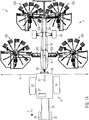
- FIG. 1A an agricultural machine 1 with the towing vehicle 2 and the attached rake 3 is shown in a plan view.
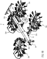
- a perspective view of the windrower 3 is in the FIG. 1B shown.
- This comprises a vehicle frame 23 with engine and transmission, two wheels 24 driven thereby and two steerable wheels 25.
- an operator can take a seat to control the towing vehicle 2.
- the machine controller 22 is shown, which is formed with a CPU, memory, various interfaces and a control unit and a display.
- the machine controller 22 is connected to the swather 3 via an interface and / or control lines, not shown here, to automatically raise or lower the rotary rakes 33a-33d independently of each other.
- the machine controller 22 is also connected via a data interface with the navigation system 21 for transmitting the position data.
- the operator on the machine control 22 can set parameters for field processing. This also includes adjusting the working width A of the rake. 3
- the navigation system 21 is arranged on the towing vehicle 2, which is designed here for example as a GPS system.
- This includes an antenna on the roof of the cabin 26 of the towing vehicle 2, in order to allow the best possible satellite reception.
- An electronic unit for calculating the position data is also part of the navigation system 21. In this way, the signals of the satellites received by the antenna are evaluated, so that the position of the towing vehicle 2 can be calculated precisely and transmitted to the machine controller 22.
- the support frame 31 of the rake 3 is attached via the hitch 34 to the towing vehicle 2 and is pulled by it. Moreover, the support frame 31 is supported between the first pair of rotary rakes 33a, 33b and the second pair of rake rotors 33c, 33d with the wheels 35 on the ground. Combined with the hitch 34 are the PTO connection for transmitting the drive force, as well as hydraulic, electrical and / or pneumatic connections. It can also be seen that the rotary rakes 33a-33d are each connected to the support frame 31 via arms 32a-32d. The arms 32a-32d can each independently raised and lowered from each other.
- hydraulic or electrical control signals from the towing vehicle 2 are transmitted to corresponding actuators mounted on the arms 32a-32d, whereby the rotary rakes 33a-33d can be pivoted into the headland position or into engagement with the crop.
- the rotary rakes 33a-33d can be pivoted into the headland position or into engagement with the crop.
- the rotary rakes 33a-33d are raised accordingly.
- the working width A can be set separately on the rotary rakes 33a, 33b of the first pair (front pair).
- the width of the rotary rakes 33c, 33d of the second pair can be adjusted together. This will change the swath width.
- FIG. 2 An exemplary embodiment of a method according to the invention for operating an agricultural machine 100 is illustrated in more detail in a flowchart.
- the steps 101 and 102 serve to prepare the processing and are therefore to be regarded as optional for the invention:
- the rake 3 is in the headland position in step 101, in which the rotary rakes 33a - 33d are raised in the headland position.
- the working width A can then be set before reaching the agricultural area.
- either the PTO shaft on the towing vehicle 2 is started automatically or manually, so that the driving force is transmitted to the attached rake 3.
- the rotary gyros 33a-33d then rotate.
- the rake 3 is brought in step 102 in the working position and the automatic control activated. For example, with an input of the operator on the machine control 22.
- step 110 the processing of the agricultural area then takes place.
- an external field area is first processed, which runs along the outer boundary of the agricultural area as a whole or a subarea.
- position data are continuously retrieved by the navigation system 21 in step 111 and processed in step 112 to a covered travel path of the windrower 3.
- This is then independent of one Field map known the distance traveled in the edited field area. Since the working width A accordingly Figure 1A is substantially perpendicular to the direction of travel F, can be calculated via an integration of the working width A via the travel of the already processed field area.
- step 113 when the already processed field area is recovered, the rotary gyros 33a-33d are automatically raised based on their positions.
- step 114 when entering a field area still to be processed, the rake rotors 33a-33d are automatically lowered independently of each other based on their positions.
- the raking rotors 33a-33d are respectively raised or lowered relative to a processing limit when a processing limit oblique to the direction of travel F is reached independently of one another on the basis of a calculation of position data of the raking rotors 33a-33d.
- coordinates or vectors of the raking gyros 33a-33d with respect to those in the Figure 1A reference point R which are stored in the machine control 22 or which are calculated dynamically with the machine control 22 at the current machine position.
- the positions of the rakes 33a-33d relative to the oblique processing limit can be determined exactly. Consequently, the rotary rakes 33a-33d can be automatically raised or lowered one by one upon reaching the machining limit.
- steps 113, 114 when the already processed field area is reverted, a first distance is taken into account as to how far the rotary rakes 33a-33d can each enter the already processed field area before they are lifted.
- a second distance when entering from the at least one already processed field area into the field area still to be processed can be taken into account, how far the raking gyros 33a-33d may still each be in the already processed field area and have already been lowered.
- Steps 111-114 are repeated continuously in a loop when processing the agricultural land.
- the procedure of FIG. 2 is called the computer program in the machine control 22 of the Figures 1A - 1B executed.
- FIG. 3 is the example of a substantially rectangular agricultural area 4, the implementation of the method of the FIG. 2 with the agricultural machine 1 from the Figures 1A-1B shown.
- the agricultural machine 1 with the towing vehicle 2 and the rake 3 is at the position P 1 before entering the agricultural area 4.
- the rake 3 is brought into the headland position, set the working width A and started the PTO on towing vehicle 2. Then the rake 3 is brought into the working position and the automatic control activated.
- the agricultural machine 1 drives along the four field boundaries.
- the processing is shown by way of example with the agricultural machine 1 at the position P 2 .
- the external field area is brought together (hatched area) and thus forms the already processed field area 41.
- Position data of the windrower 3 are continuously detected by the navigation system and the traveled distance S determined therefrom. Over the working width A then the already processed field area 41 is determined.
- the rake 3 again reaches the already processed field region 41. Since the processing limit 43 to the direction of travel F is substantially perpendicular, the raking rotors of the front pair are first raised simultaneously, the rear pair continues to work. Then then the rear pair reaches the processing limit 43, in which case its rotary rake are also raised simultaneously.
- the agricultural machine 1 turns to the position P 4 . Since the front pair now moves as the first from the already processed field area 41 in the still-to-be-processed field area 42, the rotary rake are lowered first. As a result, they are already starting to machine the field area 42 still to be processed, the rear pair still standing in the headland position. Then drives the rear pair rotary rake in the still-to-be-processed field area 42, so its rotary rake are also lowered.
- the field area 42 still to be processed is traversed in parallel field lanes.
- the turning of the agricultural machine 1 takes place in the already processed field area 41, ie in the headland.
- There the individual rotary gyros with the procedure of the FIG. 2 each automatically raised or lowered again.
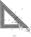
- FIG. 4 Based on FIG. 4 is the processing of a substantially triangular agricultural area 5 with the method of the FIG. 2 shown.
- the processing differs essentially from the FIG. 3 in that the processing limit 53 runs through the triangular shape of the agricultural area 5 obliquely to the direction of travel F.
- the agricultural machine 1 is in the position P 1 in the headland position, the working width A set and the PTO of the towing vehicle 2 is started. Subsequently, the processing begins along the outer field boundaries, so that the hatched, outer field area is brought together, thus forming the already processed field area 51.
- Position data of the windrower 3 are continuously detected by the navigation system and the distance traveled S determined therefrom. About the working width A then the already processed field area 51 is determined.
- the processing limit 53 When re-reaching the already processed field area 51, the processing limit 53, unlike in the FIG. 3 , obliquely to the direction of travel F. As a result, the rotary rakes are raised independently. It can be seen that, at the position P 3, first the left front rotary rake is raised, since this has reached the already processed field region 51. The opposite right rotary rake is lifted later, if he also reaches the processing limit 53. Regardless of the rear pair also first the left rotary top and then the right rotary top are raised. Depending on the configuration of the swather 3 and the course of the processing limit 53 (as in the FIG. 4 shown) are first raised the two left rotary rake and then the two rights.
- processing limit 53 is less oblique to the direction of travel F, first the front pair and then the rear pair are raised. Runs the processing limit 53 in the reverse orientation obliquely to the direction of travel, so are first raised by a pair of right raking rotary and then the left rotary rake.
- the agricultural machine turns to the position P 4 , the rotary rakes retracting from the already processed field area 51 into the field area 52 still to be processed.
- the left front rotary rake is first lowered again and begins machining first.
- the front right rotary rake is lowered when reaching the processing limit 53 later.
- the rear pair of rotary rakes is also lowered, first left and then right. This happens depending on the slope of the processing limit 53 either after the front pair or offset accordingly.
- the still to be processed field area 52 is processed in parallel field lanes, being turned in the outer field area.
- the rotary rakes are then raised and lowered automatically and independently of one another on the basis of their positions relative to the already processed field region 51.
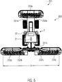
- FIG. 5 another embodiment of the agricultural machine 201 according to the invention is shown in a plan view. It can be seen that here, instead of a rake, an implement combination in the form of a mowing unit 203 is arranged on the towing vehicle.
- the towing vehicle 2 has the previously with respect to the Fig. 1A - 1B described features.
- the previously in relation to the rake 3 in the FIGS. 1A-4 described features apply mutatis mutandis to the mower 203th
- a front mower 233a and two side mowers 233b, 233c are arranged on the towing vehicle 2 as working devices (butterfly arrangement). Within the working width A, the front mower 233a mows the middle area and the side mowers 233b, 233c the two outer areas, right and left. It can also be seen that the front mower 233a and the two side mowers 233b, 233c each form a cutter bar with a plurality of mowing discs.
- the support frame is formed here by a plurality of separate units 231a, 231b, which are connected to one another via the towing vehicle 2.
- the front and side mowers 233a-233c are connected to the support frame 231a, 231b via arms 232a-232d.
- the arms 232a-232d may each be independently raised and lowered.
- hydraulic or electrical control signals from the towing vehicle 2 are transmitted to corresponding actuators mounted on the arms 232a-232d, whereby the front and side mowers 233a-233d can be pivoted to the headland position or into engagement with the crop (mowing position ).
- the above with respect to the Fig. 2 described method can mutatis mutandis in the agricultural machine 201 of the Fig. 5 be used so that the agricultural land 4, 5 of the Fig. 3 - 4th can be processed accordingly.
Landscapes
- Life Sciences & Earth Sciences (AREA)
- Environmental Sciences (AREA)
- Engineering & Computer Science (AREA)
- Mechanical Engineering (AREA)
- Soil Sciences (AREA)
- Zoology (AREA)
- Harvester Elements (AREA)
- Guiding Agricultural Machines (AREA)
Priority Applications (6)
| Application Number | Priority Date | Filing Date | Title |
|---|---|---|---|
| PL16172934T PL3251484T3 (pl) | 2016-06-03 | 2016-06-03 | Sposób oraz urządzenie do obsługi maszyny rolniczej |
| EP16172934.8A EP3251484B1 (fr) | 2016-06-03 | 2016-06-03 | Procede et dispositif destines au fonctionnement d'une machine agricole |
| PCT/EP2017/063110 WO2017207604A1 (fr) | 2016-06-03 | 2017-05-31 | Procédé et dispositif de fonctionnement d'une machine agricole |
| US16/306,567 US20190116717A1 (en) | 2016-06-03 | 2017-05-31 | Method and device for operating an agricultural machine |
| CA3025950A CA3025950A1 (fr) | 2016-06-03 | 2017-05-31 | Procede et dispositif de fonctionnement d'une machine agricole |
| AU2017275683A AU2017275683A1 (en) | 2016-06-03 | 2017-05-31 | Method and device for operating an agricultural machine |
Applications Claiming Priority (1)
| Application Number | Priority Date | Filing Date | Title |
|---|---|---|---|
| EP16172934.8A EP3251484B1 (fr) | 2016-06-03 | 2016-06-03 | Procede et dispositif destines au fonctionnement d'une machine agricole |
Publications (2)
| Publication Number | Publication Date |
|---|---|
| EP3251484A1 true EP3251484A1 (fr) | 2017-12-06 |
| EP3251484B1 EP3251484B1 (fr) | 2018-09-26 |
Family
ID=56101349
Family Applications (1)
| Application Number | Title | Priority Date | Filing Date |
|---|---|---|---|
| EP16172934.8A Revoked EP3251484B1 (fr) | 2016-06-03 | 2016-06-03 | Procede et dispositif destines au fonctionnement d'une machine agricole |
Country Status (6)
| Country | Link |
|---|---|
| US (1) | US20190116717A1 (fr) |
| EP (1) | EP3251484B1 (fr) |
| AU (1) | AU2017275683A1 (fr) |
| CA (1) | CA3025950A1 (fr) |
| PL (1) | PL3251484T3 (fr) |
| WO (1) | WO2017207604A1 (fr) |
Cited By (2)
| Publication number | Priority date | Publication date | Assignee | Title |
|---|---|---|---|---|
| EP3725150A1 (fr) * | 2019-04-12 | 2020-10-21 | AGCO International GmbH | Outil agricole |
| EP4018815A1 (fr) * | 2020-12-24 | 2022-06-29 | Kubota Corporation | Système de support agricole, procédé de génération d'informations de position, programme informatique et dispositif de traitement |
Families Citing this family (9)
| Publication number | Priority date | Publication date | Assignee | Title |
|---|---|---|---|---|
| EP3378302B1 (fr) * | 2017-03-21 | 2020-02-26 | Kverneland Group Mechatronics BV | Procédé agricole de formation d'un andain sur un champ à partir de produit agricoles préalablement coupées |
| JP7038536B2 (ja) * | 2017-12-12 | 2022-03-18 | 株式会社クボタ | 作業車両 |
| US10806079B2 (en) | 2018-02-26 | 2020-10-20 | Deere & Company | Automatic product harvesting method and control system |
| DE102019116961A1 (de) * | 2019-06-24 | 2020-12-24 | Grimme Landmaschinenfabrik Gmbh & Co. Kg | Verfahren zur Beobachtung von Arbeitsprozessen einer landwirtschaftlichen Maschine, digitales Videosystem und landwirtschaftliche Maschine |
| DE102019127447A1 (de) * | 2019-10-11 | 2021-04-15 | Pöttinger Landtechnik Gmbh | Schwader sowie Verfahren zum Steuern eines solchen Schwaders |
| GB201918845D0 (en) * | 2019-12-19 | 2020-02-05 | Agco Int Gmbh | Mower combination |
| GB202003486D0 (en) * | 2020-03-11 | 2020-04-29 | Agco Int Gmbh | Agricultural apparatus |
| GB202003487D0 (en) * | 2020-03-11 | 2020-04-29 | Agco Int Gmbh | Agricultural apparatus |
| JP7457889B2 (ja) * | 2020-12-28 | 2024-03-29 | 井関農機株式会社 | 作業車両の制御システム |
Citations (4)
| Publication number | Priority date | Publication date | Assignee | Title |
|---|---|---|---|---|
| US5077653A (en) * | 1988-11-28 | 1991-12-31 | Christian Barlet | Process and device for programmed spreading of an active product on the surface of the ground |
| EP1616470A1 (fr) * | 2004-06-28 | 2006-01-18 | CLAAS Selbstfahrende Erntemaschinen GmbH | Procédé et dispositif de guidage pour machine de travail agricole |
| EP2342963A1 (fr) * | 2010-01-08 | 2011-07-13 | Deere & Company | Procédé d'application d'entrée dans un champ agricole |
| EP2547188B1 (fr) | 2010-03-18 | 2016-02-10 | Forage Innovations B.V. | Dispositif de fenaison |
Family Cites Families (8)
| Publication number | Priority date | Publication date | Assignee | Title |
|---|---|---|---|---|
| DE4111267C2 (de) | 1990-05-14 | 2001-10-18 | Poettinger Alois Landmasch | Heuwerbungsmaschine |
| DE19647523A1 (de) | 1996-11-16 | 1998-05-20 | Claas Ohg | Landwirtschaftliches Nutzfahrzeug mit einem in seiner Lage und/oder Ausrichtung gegenüber dem Fahrzeug verstellbar angeordneten Bearbeitungsgerät |
| DE19830858A1 (de) | 1998-07-10 | 2000-01-13 | Claas Selbstfahr Erntemasch | Vorrichtung und Verfahren zur Bestimmung einer virtuellen Position |
| FR2800232B1 (fr) | 1999-10-27 | 2002-06-07 | Renault Agriculture | Procede pour le guidage automatique d'un engin et dispositif correspondant |
| US7739015B2 (en) | 2007-07-31 | 2010-06-15 | Deere & Company | System and method for controlling a vehicle with a sequence of vehicle events |
| US8463510B2 (en) | 2010-04-30 | 2013-06-11 | Cnh America Llc | GPS controlled residue spread width |
| DE102010046938A1 (de) | 2010-09-29 | 2012-04-26 | Claas Saulgau Gmbh | Verfahren und Vorrichtung zum Betreiben einer Rechkreiselaushubsteuerung |
| DE102011054630A1 (de) | 2011-10-20 | 2013-04-25 | Claas Agrosystems GmbH | Visualisierungseinrichtung |
-
2016
- 2016-06-03 EP EP16172934.8A patent/EP3251484B1/fr not_active Revoked
- 2016-06-03 PL PL16172934T patent/PL3251484T3/pl unknown
-
2017
- 2017-05-31 AU AU2017275683A patent/AU2017275683A1/en not_active Abandoned
- 2017-05-31 CA CA3025950A patent/CA3025950A1/fr not_active Abandoned
- 2017-05-31 WO PCT/EP2017/063110 patent/WO2017207604A1/fr active Application Filing
- 2017-05-31 US US16/306,567 patent/US20190116717A1/en not_active Abandoned
Patent Citations (4)
| Publication number | Priority date | Publication date | Assignee | Title |
|---|---|---|---|---|
| US5077653A (en) * | 1988-11-28 | 1991-12-31 | Christian Barlet | Process and device for programmed spreading of an active product on the surface of the ground |
| EP1616470A1 (fr) * | 2004-06-28 | 2006-01-18 | CLAAS Selbstfahrende Erntemaschinen GmbH | Procédé et dispositif de guidage pour machine de travail agricole |
| EP2342963A1 (fr) * | 2010-01-08 | 2011-07-13 | Deere & Company | Procédé d'application d'entrée dans un champ agricole |
| EP2547188B1 (fr) | 2010-03-18 | 2016-02-10 | Forage Innovations B.V. | Dispositif de fenaison |
Cited By (3)
| Publication number | Priority date | Publication date | Assignee | Title |
|---|---|---|---|---|
| EP3725150A1 (fr) * | 2019-04-12 | 2020-10-21 | AGCO International GmbH | Outil agricole |
| US11582914B2 (en) | 2019-04-12 | 2023-02-21 | Agco International Gmbh | Agricultural implement having arms movable to headland positions |
| EP4018815A1 (fr) * | 2020-12-24 | 2022-06-29 | Kubota Corporation | Système de support agricole, procédé de génération d'informations de position, programme informatique et dispositif de traitement |
Also Published As
| Publication number | Publication date |
|---|---|
| AU2017275683A1 (en) | 2019-01-17 |
| EP3251484B1 (fr) | 2018-09-26 |
| CA3025950A1 (fr) | 2017-12-07 |
| WO2017207604A1 (fr) | 2017-12-07 |
| PL3251484T3 (pl) | 2019-03-29 |
| US20190116717A1 (en) | 2019-04-25 |
Similar Documents
| Publication | Publication Date | Title |
|---|---|---|
| EP3251484B1 (fr) | Procede et dispositif destines au fonctionnement d'une machine agricole | |
| DE102006015203A1 (de) | Verfahren zur Steuerung von landwirtschaftlichen Maschinensystemen | |
| EP3289847A1 (fr) | Arrangement destiné à influencer l'emplacement d'un engin rajouté agricole | |
| EP2545761B1 (fr) | Procédé de fonctionnement d'une moissonneuse automobile | |
| EP2436252B1 (fr) | Procédé de commande à soulever des râteaux rotatifs | |
| EP1769662A1 (fr) | Unité de travail agricole avec un dispositif de travail pour la création d' une colonne d'objets | |
| EP3409088B1 (fr) | Dispositif d'enregistrement de données de trajet d'un appareil de travail agricole | |
| EP3300561A1 (fr) | Machine agricole automotrice | |
| WO2020182564A1 (fr) | Système d'aide au pilotage basé sur la vision pour des véhicules terrestres | |
| DE102020131805A1 (de) | Autonome Fahrt-Arbeitsmaschine | |
| EP3461313A1 (fr) | Engin agricole | |
| DE102020209832A1 (de) | Knickgelenktes arbeitsfahrzeug mit lenkungsauswahl | |
| EP3756433B1 (fr) | Système de commande d'un outil de travail raccordé à un véhicule | |
| EP1364573B1 (fr) | Machine de fenaison | |
| DE19950748A1 (de) | Mähgerät | |
| DE69531750T2 (de) | Heuwerbungsmaschine | |
| EP3384756B1 (fr) | Procédé de commande d'un engin agricole lors de la mise en andains d'une récolte sur une surface agricole utile et engin agricole | |
| EP3384755B1 (fr) | Procédé de commande d'une machine agricole lors de la mise en andains d'une récolte et système comprenant une machine agricole | |
| DE102017124480A1 (de) | Autonome landwirtschaftliche Robotervorrichtung | |
| DE102020114957A1 (de) | Landwirtschaftliches Anbaugerät zur Bearbeitung von Reihenkulturen | |
| DE102022109611A1 (de) | Verbesserte hindernishandhabung für ein robotisches arbeitsgerät | |
| EP4245107A1 (fr) | Procédé d'optimisation d'itinéraire | |
| DE102022126371A1 (de) | Verbesserte navigation für ein robotergestütztes arbeitsgerätesystem | |
| EP4245108A1 (fr) | Procédé d'optimisation d'itinéraire | |
| DE102023103689A1 (de) | Verbesserte navigation für ein roboterarbeitswerkzeugsystem |
Legal Events
| Date | Code | Title | Description |
|---|---|---|---|
| PUAI | Public reference made under article 153(3) epc to a published international application that has entered the european phase |
Free format text: ORIGINAL CODE: 0009012 |
|
| STAA | Information on the status of an ep patent application or granted ep patent |
Free format text: STATUS: THE APPLICATION HAS BEEN PUBLISHED |
|
| AK | Designated contracting states |
Kind code of ref document: A1 Designated state(s): AL AT BE BG CH CY CZ DE DK EE ES FI FR GB GR HR HU IE IS IT LI LT LU LV MC MK MT NL NO PL PT RO RS SE SI SK SM TR |
|
| AX | Request for extension of the european patent |
Extension state: BA ME |
|
| STAA | Information on the status of an ep patent application or granted ep patent |
Free format text: STATUS: REQUEST FOR EXAMINATION WAS MADE |
|
| 17P | Request for examination filed |
Effective date: 20180220 |
|
| RBV | Designated contracting states (corrected) |
Designated state(s): AL AT BE BG CH CY CZ DE DK EE ES FI FR GB GR HR HU IE IS IT LI LT LU LV MC MK MT NL NO PL PT RO RS SE SI SK SM TR |
|
| REG | Reference to a national code |
Ref country code: DE Ref legal event code: R079 Ref document number: 502016002063 Country of ref document: DE Free format text: PREVIOUS MAIN CLASS: A01B0079000000 Ipc: A01B0069000000 |
|
| GRAP | Despatch of communication of intention to grant a patent |
Free format text: ORIGINAL CODE: EPIDOSNIGR1 |
|
| STAA | Information on the status of an ep patent application or granted ep patent |
Free format text: STATUS: GRANT OF PATENT IS INTENDED |
|
| RIC1 | Information provided on ipc code assigned before grant |
Ipc: A01B 69/00 20060101AFI20180517BHEP |
|
| INTG | Intention to grant announced |
Effective date: 20180615 |
|
| GRAS | Grant fee paid |
Free format text: ORIGINAL CODE: EPIDOSNIGR3 |
|
| GRAA | (expected) grant |
Free format text: ORIGINAL CODE: 0009210 |
|
| STAA | Information on the status of an ep patent application or granted ep patent |
Free format text: STATUS: THE PATENT HAS BEEN GRANTED |
|
| AK | Designated contracting states |
Kind code of ref document: B1 Designated state(s): AL AT BE BG CH CY CZ DE DK EE ES FI FR GB GR HR HU IE IS IT LI LT LU LV MC MK MT NL NO PL PT RO RS SE SI SK SM TR |
|
| REG | Reference to a national code |
Ref country code: GB Ref legal event code: FG4D Free format text: NOT ENGLISH |
|
| REG | Reference to a national code |
Ref country code: CH Ref legal event code: EP |
|
| REG | Reference to a national code |
Ref country code: AT Ref legal event code: REF Ref document number: 1044893 Country of ref document: AT Kind code of ref document: T Effective date: 20181015 |
|
| REG | Reference to a national code |
Ref country code: IE Ref legal event code: FG4D Free format text: LANGUAGE OF EP DOCUMENT: GERMAN |
|
| REG | Reference to a national code |
Ref country code: DE Ref legal event code: R096 Ref document number: 502016002063 Country of ref document: DE |
|
| REG | Reference to a national code |
Ref country code: NL Ref legal event code: FP |
|
| PG25 | Lapsed in a contracting state [announced via postgrant information from national office to epo] |
Ref country code: BG Free format text: LAPSE BECAUSE OF FAILURE TO SUBMIT A TRANSLATION OF THE DESCRIPTION OR TO PAY THE FEE WITHIN THE PRESCRIBED TIME-LIMIT Effective date: 20181226 Ref country code: LT Free format text: LAPSE BECAUSE OF FAILURE TO SUBMIT A TRANSLATION OF THE DESCRIPTION OR TO PAY THE FEE WITHIN THE PRESCRIBED TIME-LIMIT Effective date: 20180926 Ref country code: GR Free format text: LAPSE BECAUSE OF FAILURE TO SUBMIT A TRANSLATION OF THE DESCRIPTION OR TO PAY THE FEE WITHIN THE PRESCRIBED TIME-LIMIT Effective date: 20181227 Ref country code: NO Free format text: LAPSE BECAUSE OF FAILURE TO SUBMIT A TRANSLATION OF THE DESCRIPTION OR TO PAY THE FEE WITHIN THE PRESCRIBED TIME-LIMIT Effective date: 20181226 Ref country code: FI Free format text: LAPSE BECAUSE OF FAILURE TO SUBMIT A TRANSLATION OF THE DESCRIPTION OR TO PAY THE FEE WITHIN THE PRESCRIBED TIME-LIMIT Effective date: 20180926 Ref country code: RS Free format text: LAPSE BECAUSE OF FAILURE TO SUBMIT A TRANSLATION OF THE DESCRIPTION OR TO PAY THE FEE WITHIN THE PRESCRIBED TIME-LIMIT Effective date: 20180926 |
|
| REG | Reference to a national code |
Ref country code: LT Ref legal event code: MG4D |
|
| PG25 | Lapsed in a contracting state [announced via postgrant information from national office to epo] |
Ref country code: AL Free format text: LAPSE BECAUSE OF FAILURE TO SUBMIT A TRANSLATION OF THE DESCRIPTION OR TO PAY THE FEE WITHIN THE PRESCRIBED TIME-LIMIT Effective date: 20180926 Ref country code: LV Free format text: LAPSE BECAUSE OF FAILURE TO SUBMIT A TRANSLATION OF THE DESCRIPTION OR TO PAY THE FEE WITHIN THE PRESCRIBED TIME-LIMIT Effective date: 20180926 Ref country code: HR Free format text: LAPSE BECAUSE OF FAILURE TO SUBMIT A TRANSLATION OF THE DESCRIPTION OR TO PAY THE FEE WITHIN THE PRESCRIBED TIME-LIMIT Effective date: 20180926 |
|
| PG25 | Lapsed in a contracting state [announced via postgrant information from national office to epo] |
Ref country code: IT Free format text: LAPSE BECAUSE OF FAILURE TO SUBMIT A TRANSLATION OF THE DESCRIPTION OR TO PAY THE FEE WITHIN THE PRESCRIBED TIME-LIMIT Effective date: 20180926 Ref country code: EE Free format text: LAPSE BECAUSE OF FAILURE TO SUBMIT A TRANSLATION OF THE DESCRIPTION OR TO PAY THE FEE WITHIN THE PRESCRIBED TIME-LIMIT Effective date: 20180926 Ref country code: ES Free format text: LAPSE BECAUSE OF FAILURE TO SUBMIT A TRANSLATION OF THE DESCRIPTION OR TO PAY THE FEE WITHIN THE PRESCRIBED TIME-LIMIT Effective date: 20180926 Ref country code: RO Free format text: LAPSE BECAUSE OF FAILURE TO SUBMIT A TRANSLATION OF THE DESCRIPTION OR TO PAY THE FEE WITHIN THE PRESCRIBED TIME-LIMIT Effective date: 20180926 Ref country code: CZ Free format text: LAPSE BECAUSE OF FAILURE TO SUBMIT A TRANSLATION OF THE DESCRIPTION OR TO PAY THE FEE WITHIN THE PRESCRIBED TIME-LIMIT Effective date: 20180926 Ref country code: IS Free format text: LAPSE BECAUSE OF FAILURE TO SUBMIT A TRANSLATION OF THE DESCRIPTION OR TO PAY THE FEE WITHIN THE PRESCRIBED TIME-LIMIT Effective date: 20190126 |
|
| PG25 | Lapsed in a contracting state [announced via postgrant information from national office to epo] |
Ref country code: PT Free format text: LAPSE BECAUSE OF FAILURE TO SUBMIT A TRANSLATION OF THE DESCRIPTION OR TO PAY THE FEE WITHIN THE PRESCRIBED TIME-LIMIT Effective date: 20190126 Ref country code: SK Free format text: LAPSE BECAUSE OF FAILURE TO SUBMIT A TRANSLATION OF THE DESCRIPTION OR TO PAY THE FEE WITHIN THE PRESCRIBED TIME-LIMIT Effective date: 20180926 Ref country code: SM Free format text: LAPSE BECAUSE OF FAILURE TO SUBMIT A TRANSLATION OF THE DESCRIPTION OR TO PAY THE FEE WITHIN THE PRESCRIBED TIME-LIMIT Effective date: 20180926 |
|
| REG | Reference to a national code |
Ref country code: DE Ref legal event code: R026 Ref document number: 502016002063 Country of ref document: DE |
|
| PLBI | Opposition filed |
Free format text: ORIGINAL CODE: 0009260 |
|
| PLBI | Opposition filed |
Free format text: ORIGINAL CODE: 0009260 |
|
| PLAB | Opposition data, opponent's data or that of the opponent's representative modified |
Free format text: ORIGINAL CODE: 0009299OPPO |
|
| PLBI | Opposition filed |
Free format text: ORIGINAL CODE: 0009260 |
|
| PLAX | Notice of opposition and request to file observation + time limit sent |
Free format text: ORIGINAL CODE: EPIDOSNOBS2 |
|
| 26 | Opposition filed |
Opponent name: DEERE & COMPANY Effective date: 20190619 |
|
| 26 | Opposition filed |
Opponent name: KUHN S.A. Effective date: 20190625 Opponent name: MASCHINENFABRIK BERNARD KRONE GMBH & CO. KG Effective date: 20190624 |
|
| PG25 | Lapsed in a contracting state [announced via postgrant information from national office to epo] |
Ref country code: DK Free format text: LAPSE BECAUSE OF FAILURE TO SUBMIT A TRANSLATION OF THE DESCRIPTION OR TO PAY THE FEE WITHIN THE PRESCRIBED TIME-LIMIT Effective date: 20180926 |
|
| 26 | Opposition filed |
Opponent name: POETTINGER LANDTECHNIK GMBH Effective date: 20190626 |
|
| R26 | Opposition filed (corrected) |
Opponent name: DEERE & COMPANY/JOHN DEERE GMBH & CO. KG Effective date: 20190619 |
|
| PG25 | Lapsed in a contracting state [announced via postgrant information from national office to epo] |
Ref country code: SI Free format text: LAPSE BECAUSE OF FAILURE TO SUBMIT A TRANSLATION OF THE DESCRIPTION OR TO PAY THE FEE WITHIN THE PRESCRIBED TIME-LIMIT Effective date: 20180926 |
|
| PLBB | Reply of patent proprietor to notice(s) of opposition received |
Free format text: ORIGINAL CODE: EPIDOSNOBS3 |
|
| PG25 | Lapsed in a contracting state [announced via postgrant information from national office to epo] |
Ref country code: MC Free format text: LAPSE BECAUSE OF FAILURE TO SUBMIT A TRANSLATION OF THE DESCRIPTION OR TO PAY THE FEE WITHIN THE PRESCRIBED TIME-LIMIT Effective date: 20180926 |
|
| REG | Reference to a national code |
Ref country code: CH Ref legal event code: PL |
|
| REG | Reference to a national code |
Ref country code: BE Ref legal event code: MM Effective date: 20190630 |
|
| PG25 | Lapsed in a contracting state [announced via postgrant information from national office to epo] |
Ref country code: TR Free format text: LAPSE BECAUSE OF FAILURE TO SUBMIT A TRANSLATION OF THE DESCRIPTION OR TO PAY THE FEE WITHIN THE PRESCRIBED TIME-LIMIT Effective date: 20180926 |
|
| PG25 | Lapsed in a contracting state [announced via postgrant information from national office to epo] |
Ref country code: IE Free format text: LAPSE BECAUSE OF NON-PAYMENT OF DUE FEES Effective date: 20190603 |
|
| PG25 | Lapsed in a contracting state [announced via postgrant information from national office to epo] |
Ref country code: CH Free format text: LAPSE BECAUSE OF NON-PAYMENT OF DUE FEES Effective date: 20190630 Ref country code: LI Free format text: LAPSE BECAUSE OF NON-PAYMENT OF DUE FEES Effective date: 20190630 Ref country code: BE Free format text: LAPSE BECAUSE OF NON-PAYMENT OF DUE FEES Effective date: 20190630 Ref country code: LU Free format text: LAPSE BECAUSE OF NON-PAYMENT OF DUE FEES Effective date: 20190603 |
|
| PLAB | Opposition data, opponent's data or that of the opponent's representative modified |
Free format text: ORIGINAL CODE: 0009299OPPO |
|
| R26 | Opposition filed (corrected) |
Opponent name: KUHN SAS Effective date: 20190625 |
|
| PGFP | Annual fee paid to national office [announced via postgrant information from national office to epo] |
Ref country code: FR Payment date: 20200619 Year of fee payment: 5 Ref country code: DE Payment date: 20200618 Year of fee payment: 5 |
|
| PGFP | Annual fee paid to national office [announced via postgrant information from national office to epo] |
Ref country code: NL Payment date: 20200625 Year of fee payment: 5 Ref country code: PL Payment date: 20200521 Year of fee payment: 5 |
|
| PLAB | Opposition data, opponent's data or that of the opponent's representative modified |
Free format text: ORIGINAL CODE: 0009299OPPO |
|
| R26 | Opposition filed (corrected) |
Opponent name: KUHN SAS Effective date: 20190625 |
|
| GBPC | Gb: european patent ceased through non-payment of renewal fee |
Effective date: 20200603 |
|
| PG25 | Lapsed in a contracting state [announced via postgrant information from national office to epo] |
Ref country code: GB Free format text: LAPSE BECAUSE OF NON-PAYMENT OF DUE FEES Effective date: 20200603 |
|
| RDAF | Communication despatched that patent is revoked |
Free format text: ORIGINAL CODE: EPIDOSNREV1 |
|
| REG | Reference to a national code |
Ref country code: DE Ref legal event code: R103 Ref document number: 502016002063 Country of ref document: DE Ref country code: DE Ref legal event code: R064 Ref document number: 502016002063 Country of ref document: DE |
|
| PG25 | Lapsed in a contracting state [announced via postgrant information from national office to epo] |
Ref country code: CY Free format text: LAPSE BECAUSE OF FAILURE TO SUBMIT A TRANSLATION OF THE DESCRIPTION OR TO PAY THE FEE WITHIN THE PRESCRIBED TIME-LIMIT Effective date: 20180926 |
|
| PG25 | Lapsed in a contracting state [announced via postgrant information from national office to epo] |
Ref country code: SE Free format text: LAPSE BECAUSE OF NON-PAYMENT OF DUE FEES Effective date: 20180926 |
|
| PG25 | Lapsed in a contracting state [announced via postgrant information from national office to epo] |
Ref country code: MT Free format text: LAPSE BECAUSE OF FAILURE TO SUBMIT A TRANSLATION OF THE DESCRIPTION OR TO PAY THE FEE WITHIN THE PRESCRIBED TIME-LIMIT Effective date: 20180926 Ref country code: HU Free format text: LAPSE BECAUSE OF FAILURE TO SUBMIT A TRANSLATION OF THE DESCRIPTION OR TO PAY THE FEE WITHIN THE PRESCRIBED TIME-LIMIT; INVALID AB INITIO Effective date: 20160603 |
|
| RDAG | Patent revoked |
Free format text: ORIGINAL CODE: 0009271 |
|
| STAA | Information on the status of an ep patent application or granted ep patent |
Free format text: STATUS: PATENT REVOKED |
|
| REG | Reference to a national code |
Ref country code: CH Ref legal event code: PL |
|
| REG | Reference to a national code |
Ref country code: FI Ref legal event code: MGE |
|
| 27W | Patent revoked |
Effective date: 20210522 |
|
| REG | Reference to a national code |
Ref country code: AT Ref legal event code: MA03 Ref document number: 1044893 Country of ref document: AT Kind code of ref document: T Effective date: 20210522 |
|
| PG25 | Lapsed in a contracting state [announced via postgrant information from national office to epo] |
Ref country code: MK Free format text: LAPSE BECAUSE OF FAILURE TO SUBMIT A TRANSLATION OF THE DESCRIPTION OR TO PAY THE FEE WITHIN THE PRESCRIBED TIME-LIMIT Effective date: 20180926 |