EP3249785A1 - Motor housing and motor including same - Google Patents
Motor housing and motor including same Download PDFInfo
- Publication number
- EP3249785A1 EP3249785A1 EP15879092.3A EP15879092A EP3249785A1 EP 3249785 A1 EP3249785 A1 EP 3249785A1 EP 15879092 A EP15879092 A EP 15879092A EP 3249785 A1 EP3249785 A1 EP 3249785A1
- Authority
- EP
- European Patent Office
- Prior art keywords
- motor
- stepped
- housing
- bearing
- pocket portion
- Prior art date
- Legal status (The legal status is an assumption and is not a legal conclusion. Google has not performed a legal analysis and makes no representation as to the accuracy of the status listed.)
- Granted
Links
Images




Classifications
-
- H—ELECTRICITY
- H02—GENERATION; CONVERSION OR DISTRIBUTION OF ELECTRIC POWER
- H02K—DYNAMO-ELECTRIC MACHINES
- H02K5/00—Casings; Enclosures; Supports
- H02K5/04—Casings or enclosures characterised by the shape, form or construction thereof
- H02K5/16—Means for supporting bearings, e.g. insulating supports or means for fitting bearings in the bearing-shields
- H02K5/163—Means for supporting bearings, e.g. insulating supports or means for fitting bearings in the bearing-shields radially supporting the rotary shaft at only one end of the rotor
-
- H—ELECTRICITY
- H02—GENERATION; CONVERSION OR DISTRIBUTION OF ELECTRIC POWER
- H02K—DYNAMO-ELECTRIC MACHINES
- H02K5/00—Casings; Enclosures; Supports
- H02K5/04—Casings or enclosures characterised by the shape, form or construction thereof
- H02K5/10—Casings or enclosures characterised by the shape, form or construction thereof with arrangements for protection from ingress, e.g. water or fingers
-
- H—ELECTRICITY
- H02—GENERATION; CONVERSION OR DISTRIBUTION OF ELECTRIC POWER
- H02K—DYNAMO-ELECTRIC MACHINES
- H02K5/00—Casings; Enclosures; Supports
- H02K5/04—Casings or enclosures characterised by the shape, form or construction thereof
- H02K5/16—Means for supporting bearings, e.g. insulating supports or means for fitting bearings in the bearing-shields
- H02K5/173—Means for supporting bearings, e.g. insulating supports or means for fitting bearings in the bearing-shields using bearings with rolling contact, e.g. ball bearings
-
- H—ELECTRICITY
- H02—GENERATION; CONVERSION OR DISTRIBUTION OF ELECTRIC POWER
- H02K—DYNAMO-ELECTRIC MACHINES
- H02K7/00—Arrangements for handling mechanical energy structurally associated with dynamo-electric machines, e.g. structural association with mechanical driving motors or auxiliary dynamo-electric machines
- H02K7/08—Structural association with bearings
Definitions
- the present invention relates to a motor housing and a motor including the same, and more particularly, to a motor housing including a bearing pocket portion configured to accommodate a bearing and a motor including the same.
- Motors are apparatuses which convert electrical energy into rotational energy using a force received by a conductor in a magnetic field. Recently, as a use of the motor expands, a role of the motor becomes important. Particularly, as the number of electrical devices in vehicles rapidly increases, demand for the motor applied to a steering system, a braking system, a safety critical system, and the like is greatly increasing.
- abraded materials may be discharged from a motor housing, a wave washer, a bearing, and the like.
- the abraded materials may fatally affect the performance of a driving apparatus, a measurement apparatus, or other application apparatuses, such as a gear or sensor, adjacent to the motor.
- driving of the motor is delayed or the motor is not driven.
- the present invention is directed to a motor housing capable of preventing foreign materials discharged from the motor housing, a wave washer, a bearing, and the like from exiting the motor to the outside and a motor including the same
- the present invention is also directed to a motor housing including a bearing and a wave washer installed therein to prevent foreign materials from exiting a bearing pocket portion, in which many foreign materials are generated, to the outside through a shaft hole, and a motor including the same.
- One aspect of the present invention provides a housing of a motor including a bearing pocket portion which is formed to protrude from an inner lower portion of the housing and in which an accommodation space of a bearing configured to support a shaft is formed and a shaft hole through which the shaft passes is formed in a bottom surface thereof, wherein the bearing pocket portion includes a stepped portion, the stepped portion protrudes upward along a circumference of the shaft hole, and an accommodation groove is formed between the stepped portion and an inner wall of the bearing pocket portion.
- the bottom surface of the bearing pocket portion forming the accommodation groove may be formed with at least two stepped surfaces in a radial direction.
- An innermost stepped surface closest to the shaft hole, among the stepped surfaces, may be formed in a flat shape to be in contact with a wave washer.
- the stepped surfaces may be formed in annular shapes and gradually lowered in the radial direction.
- Grooves may be concavely formed in the stepped portion in a circumferential direction to be spaced a predetermined distance from each other such that a depth of each of the grooves is equal to a height of the stepped surface.
- the innermost stepped surface may have a saw tooth shape.
- a motor including a housing, a stator coupled to the housing, a rotor disposed inside the stator, a shaft coupled to the rotor, and a bearing pocket portion which is formed to protrude from an inner lower portion of the housing and in which an accommodation space of a bearing configured to support the shaft is formed and a shaft hole through which the shaft passes is formed in a bottom surface thereof, wherein the bearing pocket portion includes a stepped portion, the stepped portion protrudes upward along a circumference of the shaft hole, and an accommodation groove is formed between the stepped portion and an inner wall of the bearing pocket portion.
- the bottom surface of the bearing pocket portion forming the accommodation groove may be formed with at least two stepped surfaces in a radial direction.
- An innermost stepped surface closest to the shaft hole, among the stepped surfaces, may be formed in a flat shape to be in contact with a wave washer.
- the stepped surfaces may be formed in annular shapes and gradually lowered in the radial direction.
- Grooves may be concavely formed in an upper surface of the stepped portion in a circumferential direction to be spaced a predetermined distance from each other such that a depth of each of the grooves is equal to a height of the innermost stepped surface.
- the stepped portion may have a saw tooth shape.
- the motor may further includes a bearing inserted into the bearing pocket portion and a sealing member disposed between an inner wall of the bearing pocket portion and the bearing.
- the bearing may include a sealing groove which is concavely formed in a circumference of a side of an outer race and into which the sealing member is inserted.
- a stepped portion which defines an accommodation groove around a shaft hole of a bearing pocket portion is provided, there is an advantageous effect in that foreign materials discharged from a motor housing, a wave washer, a bearing, and the like can be prevented from exiting the outside through a shaft hole.
- a bottom surface of a bearing pocket portion is formed to have a double step structure in a radial direction, there are advantageous effects in that a seating space of a wave washer is secured and an accommodation groove is also formed.
- a stepped portion is formed in a saw tooth shape to trap foreign materials in grooves between saw teeth, there is an advantageous effect in that foreign materials are effectively prevented from exiting through a shaft hole.
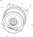
- FIG. 1 is a view illustrating a motor according to an exemplary embodiment of the present invention.
- the motor may include a housing 100, a stator 200, a rotor 300, and a shaft 400.
- the housing 100 is formed in a cylindrical shape and provided with a space in which the stator 200 and the rotor 300 may be installed.
- a shape and a material of the housing 100 may be variously changed, and a metal material capable of withstanding a high temperature may be selected for the housing 100 because the housing is installed in a vehicle.
- the housing 100 may be formed to shield the stator 200 and the rotor 300 from the outside.
- a bearing pocket portion 110 may be formed to protrude from a central portion of an inner bottom surface of the housing 100.
- the bearing pocket portion 110 may be formed by being surrounded by an annular inner wall 110a so as to define an accommodation space of the bearing 500 therein.
- an upper portion of the bearing pocket portion 110 may open, and a shaft hole 112 through which the shaft 400 passes is formed in a bottom surface 111 of the bearing pocket portion 110.
- a wave washer may be installed between the bearing 500 and the bottom surface 111.
- the stator 200 may be disposed to be spaced a predetermined distance from the inner circumferential surface of the housing 100, and a space may be formed at a center of the stator 200.
- the rotor 300 may be rotatably installed in a state in which the rotor 300 is accommodated in the space of the stator 200.
- the stator 200 may be formed with a plurality of stator cores, and a coil configured to generate a rotational magnetic field may be wound around each of the stator cores.
- the coil wound around the stator core may be covered and insulated by an insulator.
- the present invention is not limited thereto, and the stator may be formed as a single core type.
- FIG. 2 is a view illustrating a housing of a motor according to a first exemplary embodiment of the present invention
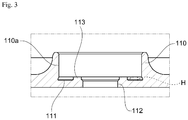
- FIG. 3 is a view illustrating a bearing pocket portion of the housing illustrated in FIG. 2
- FIG. 4 is a view illustrating an accommodation groove of the housing illustrated in FIG. 2 .
- FIGS. 2 to 4 are the views clearly illustrating main features for a clear conceptual understanding of the present invention, and thus various modifications are expected and the scope of the present invention is not limited to specific shapes illustrated in the drawings.
- a bearing pocket portion 110 including an accommodation space S for a bearing is formed in a lower portion of a housing 100, and a stepped portion 113 which defines an accommodation groove H may be formed in the bearing pocket portion 110.
- the accommodation groove H is formed between the stepped portion 113 and an inner wall 110a of the bearing pocket portion 110.
- the stepped portion 113 has an entirely protrusive annular partition structure.
- the accommodation groove H is concavely formed between the inner wall 110a of the bearing pocket portion 110 and the stepped portion 113, the accommodation groove H traps foreign materials discharged from a motor housing, a wave washer, a bearing, and the like, and thus the foreign materials may be prevented from exiting through the shaft hole 112,
- a height of the stepped portion 113 may be appropriately changed in consideration of a size of the bearing 500 and whether a wave washer W is installed.
- a bottom surface 111 of the bearing pocket portion 110 forming the accommodation groove H is illustrated in a flat shape, the present invention is not limited thereto, and the bottom surface 111 may be changed to be concave to extend a volume of the accommodation groove H.
- FIG. 5 is a view illustrating a bearing pocket portion of a housing of a motor according to a second exemplary embodiment of the present invention
- FIG. 6 is a view illustrating an accommodation groove of the housing illustrated in FIG. 5.
- FIGS. 5 and 6 are the views clearly illustrating main features for a clear conceptual understanding of the present invention, and thus various modifications are expected and the scope of the present invention is not limited to specific shapes illustrated in the drawings.
- an accommodation groove H defined by a stepped portion 113 may be formed in a double step structure.
- a bottom surface 111 of a bearing pocket portion 110 may be formed with two stepped surfaces 111a and 111b in a radial direction of a housing 100.
- the two stepped surfaces 111a and 111b may be formed as annular stepped surfaces which are gradually lowered in the radial direction.
- a wave washer W may be installed on the stepped surface 111a which is adjacent to the shaft hole 112 and refers to an inner stepped surface among two stepped surfaces 111a and 111b.
- the stepped surface 111a may be formed in a flat shape such that the wave washer W is stably seated thereon.
- An accommodation groove H is defined by the stepped surface 111b which is located at an outside of the stepped surface 111a and refers to an outer stepped surface.
- a seating space of the wave washer W is secured by the stepped portion 113, and the accommodation groove H is also defined by the stepped portion 113.
- a motor housing according to a third embodiment.
- FIG. 7 is a view illustrating a bearing pocket portion of a housing of the motor according to a third exemplary embodiment of the present invention
- FIG. 8 is a view illustrating the accommodation groove of the housing illustrated in FIG. 7.
- FIGS. 7 and 8 are the views clearly illustrating main features for a clear conceptual understanding of the present invention, and thus various modifications are expected and the scope of the present invention is not limited to specific shapes illustrated in the drawings.
- an accommodation groove H defined by a stepped portion 113 may be formed in a double step structure, and grooves 113a may be formed in the stepped portion 113 to be spaced a predetermined distance from each other in a circumferential direction. Each of the grooves 113a may be concavely formed up to an inner stepped surface 111a.
- the stepped portion 113 may be substantially formed in a saw tooth shape. Since the groove 113a traps foreign materials which pass the stepped portion 113 and exit through shaft hole 112, the foreign materials may be effectively prevented from exiting.
- FIG. 9 is a view illustrating a sealing member and a sealing groove of a bearing.
- a bearing 500 is inserted into a bearing pocket portion 110, and a sealing member 600 may be installed between an inner wall 110a of the bearing pocket portion 110 and an outer race of the bearing 500.
- the sealing member 600 prevents foreign materials accommodated in the accommodation groove H from exiting through a gap between the inner wall 110a of the bearing pocket portion 110 and the bearing 500 to effectively prevent the foreign materials exiting through the shaft hole.
- a sealing groove 510 which is concavely formed along a circumference of a side of the outer race of the bearing 500 and into which the sealing member 600 is inserted may be formed.
- H ACCOMMODATION GROOVE 100: HOUSING 110: BEARING POCKET PORTION 110a: INNER WALL 111a, 111b: STEPPED SURFACE 111: BOTTOM SURFACE 112: SHAFT HOLE 113: STEPPED PORTION 113a: GROOVE 200: STATOR 300: ROTOR 400: SHAFT 500: BEARING 510: SEALING GROOVE 600: SEALING MEMBER
Landscapes
- Engineering & Computer Science (AREA)
- Power Engineering (AREA)
- Motor Or Generator Frames (AREA)
Abstract
Description
- The present invention relates to a motor housing and a motor including the same, and more particularly, to a motor housing including a bearing pocket portion configured to accommodate a bearing and a motor including the same.
- Motors are apparatuses which convert electrical energy into rotational energy using a force received by a conductor in a magnetic field. Recently, as a use of the motor expands, a role of the motor becomes important. Particularly, as the number of electrical devices in vehicles rapidly increases, demand for the motor applied to a steering system, a braking system, a safety critical system, and the like is greatly increasing.
- Particularly, a case in which an external force is applied to a motor in a direction of a shaft is increasing. Accordingly, motors combined with a bearing configured to support a load in a direction of a shaft, such as an angular bearing, and a wave washer have been suggested.
- However, when vibrations are continuously applied to a motor and the motor is repeatedly driven, abraded materials may be discharged from a motor housing, a wave washer, a bearing, and the like. In the case in which such abraded materials exit the motor to the outside, the abraded materials may fatally affect the performance of a driving apparatus, a measurement apparatus, or other application apparatuses, such as a gear or sensor, adjacent to the motor. Particularly, in the case in which the abraded materials come into contact with the sensor, there may be a problem in that driving of the motor is delayed or the motor is not driven.
- The present invention is directed to a motor housing capable of preventing foreign materials discharged from the motor housing, a wave washer, a bearing, and the like from exiting the motor to the outside and a motor including the same
- Particularly, the present invention is also directed to a motor housing including a bearing and a wave washer installed therein to prevent foreign materials from exiting a bearing pocket portion, in which many foreign materials are generated, to the outside through a shaft hole, and a motor including the same.
- The scope of the present invention is not limited to the above-described objects, and other unmentioned objects may be clearly understood by those skilled in the art from the following descriptions
- One aspect of the present invention provides a housing of a motor including a bearing pocket portion which is formed to protrude from an inner lower portion of the housing and in which an accommodation space of a bearing configured to support a shaft is formed and a shaft hole through which the shaft passes is formed in a bottom surface thereof, wherein the bearing pocket portion includes a stepped portion, the stepped portion protrudes upward along a circumference of the shaft hole, and an accommodation groove is formed between the stepped portion and an inner wall of the bearing pocket portion.
- The bottom surface of the bearing pocket portion forming the accommodation groove may be formed with at least two stepped surfaces in a radial direction.
- An innermost stepped surface closest to the shaft hole, among the stepped surfaces, may be formed in a flat shape to be in contact with a wave washer.
- The stepped surfaces may be formed in annular shapes and gradually lowered in the radial direction.
- Grooves may be concavely formed in the stepped portion in a circumferential direction to be spaced a predetermined distance from each other such that a depth of each of the grooves is equal to a height of the stepped surface.
- The innermost stepped surface may have a saw tooth shape.
- Another aspect of the present invention provides a motor including a housing, a stator coupled to the housing, a rotor disposed inside the stator, a shaft coupled to the rotor, and a bearing pocket portion which is formed to protrude from an inner lower portion of the housing and in which an accommodation space of a bearing configured to support the shaft is formed and a shaft hole through which the shaft passes is formed in a bottom surface thereof, wherein the bearing pocket portion includes a stepped portion, the stepped portion protrudes upward along a circumference of the shaft hole, and an accommodation groove is formed between the stepped portion and an inner wall of the bearing pocket portion.
- The bottom surface of the bearing pocket portion forming the accommodation groove may be formed with at least two stepped surfaces in a radial direction.
- An innermost stepped surface closest to the shaft hole, among the stepped surfaces, may be formed in a flat shape to be in contact with a wave washer.
- The stepped surfaces may be formed in annular shapes and gradually lowered in the radial direction.
- Grooves may be concavely formed in an upper surface of the stepped portion in a circumferential direction to be spaced a predetermined distance from each other such that a depth of each of the grooves is equal to a height of the innermost stepped surface.
- The stepped portion may have a saw tooth shape.
- The motor may further includes a bearing inserted into the bearing pocket portion and a sealing member disposed between an inner wall of the bearing pocket portion and the bearing.
- The bearing may include a sealing groove which is concavely formed in a circumference of a side of an outer race and into which the sealing member is inserted.
- According to one embodiment of the present invention, since a stepped portion which defines an accommodation groove around a shaft hole of a bearing pocket portion is provided, there is an advantageous effect in that foreign materials discharged from a motor housing, a wave washer, a bearing, and the like can be prevented from exiting the outside through a shaft hole.
- In addition, according to one embodiment of the present invention, since a bottom surface of a bearing pocket portion is formed to have a double step structure in a radial direction, there are advantageous effects in that a seating space of a wave washer is secured and an accommodation groove is also formed.
- In addition, according to one embodiment of the present invention, since a stepped portion is formed in a saw tooth shape to trap foreign materials in grooves between saw teeth, there is an advantageous effect in that foreign materials are effectively prevented from exiting through a shaft hole.
-
-
FIG. 1 is a view illustrating a motor according to an exemplary embodiment of the present invention. -
FIG. 2 is a view illustrating a housing of a motor according to a first exemplary embodiment of the present invention. -
FIG. 3 is a view illustrating a bearing pocket portion of the housing illustrated inFIG. 2 . -
FIG. 4 is a view illustrating an accommodation groove of the housing illustrated inFIG. 2 . -
FIG. 5 is a view illustrating a bearing pocket portion of a housing of a motor according to a second exemplary embodiment of the present invention. -
FIG. 6 is a view illustrating an accommodation groove of the housing illustrated inFIG. 5 . -
FIG. 7 is a view illustrating a bearing pocket portion of a housing of the motor according to a third exemplary embodiment of the present invention. -
FIG. 8 is a view illustrating the accommodation groove of the housing illustrated inFIG. 7 . -
FIG. 9 is a view illustrating a sealing member and a sealing groove of a bearing. - Hereinafter, exemplary embodiments of the present invention will be described in detail with reference to the accompanying drawings. Purposes, specific advantages, and novel features of the present invention will be made clear from the exemplary embodiments and the following detailed description in connection with the accompanying drawings. Terms and words used in this specification and claims thereof are not to be interpreted as limited to commonly used meanings or meanings in dictionaries, and should be interpreted as having meanings and concepts which are consistent with the technological scope of the present invention based on the principle that the inventors have appropriately defined concepts of terms in order to describe the present invention in the best way. In the description of the present invention, when it is determined that detailed descriptions of related well-known functions unnecessarily obscure the gist of the present invention, the detailed descriptions will be omitted.
-
FIG. 1 is a view illustrating a motor according to an exemplary embodiment of the present invention. - Referring to
FIG. 1 , the motor according to the embodiment of the present invention may include ahousing 100, astator 200, arotor 300, and ashaft 400. - The
housing 100 is formed in a cylindrical shape and provided with a space in which thestator 200 and therotor 300 may be installed. Here, a shape and a material of thehousing 100 may be variously changed, and a metal material capable of withstanding a high temperature may be selected for thehousing 100 because the housing is installed in a vehicle. In addition, thehousing 100 may be formed to shield thestator 200 and therotor 300 from the outside. - A
bearing pocket portion 110 may be formed to protrude from a central portion of an inner bottom surface of thehousing 100. The bearingpocket portion 110 may be formed by being surrounded by an annularinner wall 110a so as to define an accommodation space of the bearing 500 therein. Here, an upper portion of thebearing pocket portion 110 may open, and ashaft hole 112 through which theshaft 400 passes is formed in abottom surface 111 of thebearing pocket portion 110. - Foreign materials may exit the motor to the outside through the
shaft hole 112. Meanwhile, a wave washer may be installed between the bearing 500 and thebottom surface 111. - The
stator 200 may be disposed to be spaced a predetermined distance from the inner circumferential surface of thehousing 100, and a space may be formed at a center of thestator 200. - The
rotor 300 may be rotatably installed in a state in which therotor 300 is accommodated in the space of thestator 200. Thestator 200 may be formed with a plurality of stator cores, and a coil configured to generate a rotational magnetic field may be wound around each of the stator cores. The coil wound around the stator core may be covered and insulated by an insulator. However, the present invention is not limited thereto, and the stator may be formed as a single core type. - When a current is supplied to the coil wound around the
stator 200, an electrical interaction with therotor 300 occurs to induce rotation of therotor 300. When therotor 300 rotates, theshaft 400 is rotated to supply power. - A housing of a motor according to a first embodiment
-
FIG. 2 is a view illustrating a housing of a motor according to a first exemplary embodiment of the present invention,FIG. 3 is a view illustrating a bearing pocket portion of the housing illustrated inFIG. 2 , andFIG. 4 is a view illustrating an accommodation groove of the housing illustrated inFIG. 2 .FIGS. 2 to 4 are the views clearly illustrating main features for a clear conceptual understanding of the present invention, and thus various modifications are expected and the scope of the present invention is not limited to specific shapes illustrated in the drawings. - Referring to
FIGS. 2 to 4 , abearing pocket portion 110 including an accommodation space S for a bearing is formed in a lower portion of ahousing 100, and a steppedportion 113 which defines an accommodation groove H may be formed in thebearing pocket portion 110. - As the stepped
portion 113 protrudes upward along a circumference of theshaft hole 112, the accommodation groove H is formed between the steppedportion 113 and aninner wall 110a of thebearing pocket portion 110. The steppedportion 113 has an entirely protrusive annular partition structure. - Since the accommodation groove H is concavely formed between the
inner wall 110a of thebearing pocket portion 110 and the steppedportion 113, the accommodation groove H traps foreign materials discharged from a motor housing, a wave washer, a bearing, and the like, and thus the foreign materials may be prevented from exiting through theshaft hole 112, - A height of the stepped
portion 113 may be appropriately changed in consideration of a size of thebearing 500 and whether a wave washer W is installed. - Meanwhile, although a
bottom surface 111 of thebearing pocket portion 110 forming the accommodation groove H is illustrated in a flat shape, the present invention is not limited thereto, and thebottom surface 111 may be changed to be concave to extend a volume of the accommodation groove H. - A motor housing according to a second embodiment
-
FIG. 5 is a view illustrating a bearing pocket portion of a housing of a motor according to a second exemplary embodiment of the present invention, andFIG. 6 is a view illustrating an accommodation groove of the housing illustrated inFIG. 5. FIGS. 5 and6 are the views clearly illustrating main features for a clear conceptual understanding of the present invention, and thus various modifications are expected and the scope of the present invention is not limited to specific shapes illustrated in the drawings. - Referring to
FIGS. 5 and6 , an accommodation groove H defined by a steppedportion 113 may be formed in a double step structure. Specifically, abottom surface 111 of abearing pocket portion 110 may be formed with two steppedsurfaces housing 100. The two steppedsurfaces - Here, a wave washer W may be installed on the stepped
surface 111a which is adjacent to theshaft hole 112 and refers to an inner stepped surface among two steppedsurfaces surface 111a may be formed in a flat shape such that the wave washer W is stably seated thereon. - An accommodation groove H is defined by the stepped
surface 111b which is located at an outside of the steppedsurface 111a and refers to an outer stepped surface. - A seating space of the wave washer W is secured by the stepped
portion 113, and the accommodation groove H is also defined by the steppedportion 113. - A motor housing according to a third embodiment.
-
FIG. 7 is a view illustrating a bearing pocket portion of a housing of the motor according to a third exemplary embodiment of the present invention, andFIG. 8 is a view illustrating the accommodation groove of the housing illustrated inFIG. 7. FIGS. 7 and8 are the views clearly illustrating main features for a clear conceptual understanding of the present invention, and thus various modifications are expected and the scope of the present invention is not limited to specific shapes illustrated in the drawings. - Referring to
FIGS. 7 to 8 , an accommodation groove H defined by a steppedportion 113 may be formed in a double step structure, andgrooves 113a may be formed in the steppedportion 113 to be spaced a predetermined distance from each other in a circumferential direction. Each of thegrooves 113a may be concavely formed up to an inner steppedsurface 111a. - For example, the stepped
portion 113 may be substantially formed in a saw tooth shape. Since thegroove 113a traps foreign materials which pass the steppedportion 113 and exit throughshaft hole 112, the foreign materials may be effectively prevented from exiting. -
FIG. 9 is a view illustrating a sealing member and a sealing groove of a bearing. - Referring to
FIG. 9 , abearing 500 is inserted into abearing pocket portion 110, and a sealingmember 600 may be installed between aninner wall 110a of thebearing pocket portion 110 and an outer race of thebearing 500. The sealingmember 600 prevents foreign materials accommodated in the accommodation groove H from exiting through a gap between theinner wall 110a of thebearing pocket portion 110 and thebearing 500 to effectively prevent the foreign materials exiting through the shaft hole. - Meanwhile, a sealing
groove 510 which is concavely formed along a circumference of a side of the outer race of thebearing 500 and into which the sealingmember 600 is inserted may be formed. - The housing of the motor and the motor including the same according to the exemplary embodiment of the present invention have been specifically described above with reference to the accompanying drawings.
- While the present invention has been particularly described with reference to the exemplary embodiments, those skilled in the art should understand that various changes in form and details may be made without departing from the spirit and scope of the present invention. Therefore, the exemplary embodiments should be considered in a descriptive sense only and not for purposes of limitation. The scope of the present invention is defined not by the detailed description of the present invention but by the appended claims, and encompasses all modifications and equivalents that fall within the scope of the appended claims.
[Reference Numerals] H: ACCOMMODATION GROOVE 100: HOUSING 110: BEARING POCKET PORTION 110a: INNER WALL 111a, 111b: STEPPED SURFACE 111: BOTTOM SURFACE 112: SHAFT HOLE 113: STEPPED PORTION 113a: GROOVE 200: STATOR 300: ROTOR 400: SHAFT 500: BEARING 510: SEALING GROOVE 600: SEALING MEMBER
Claims (14)
- A housing of a motor comprising a bearing pocket portion which is formed to protrude from an inner lower portion of the housing and in which an accommodation space of a bearing configured to support a shaft is formed and a shaft hole through which the shaft passes is formed in a bottom surface thereof, wherein:the bearing pocket portion includes a stepped portion;the stepped portion protrudes upward along a circumference of the shaft hole; andan accommodation groove is formed between the stepped portion and an inner wall of the bearing pocket portion.
- The housing of a motor of claim 1, wherein the bottom surface of the bearing pocket portion forming the accommodation groove is formed with at least two stepped surfaces in a radial direction.
- The housing of a motor of claim 2, wherein an innermost stepped surface closest to the shaft hole, among the stepped surfaces, is formed in a flat shape to be in contact with a wave washer.
- The housing of a motor of claim 3, wherein the stepped surfaces are formed in annular shapes and gradually lowered in the radial direction.
- The housing of a motor of claim 4, wherein grooves are concavely formed in the stepped portion in a circumferential direction to be spaced a predetermined distance from each other such that a depth of each of the grooves is equal to a height of the stepped surface.
- The housing of a motor of claim 5, wherein the innermost stepped surface has a saw tooth shape.
- A motor comprising:a housing;a stator coupled to the housing;a rotor disposed inside the stator;a shaft coupled to the rotor; anda bearing pocket portion which is formed to protrude from an inner lower portion of the housing and in which an accommodation space of a bearing configured to support the shaft is formed and a shaft hole through which the shaft passes is formed in a bottom surface thereof, wherein:the bearing pocket portion includes a stepped portion;the stepped portion protrudes upward along a circumference of the shaft hole; andan accommodation groove is formed between the stepped portion and an inner wall of the bearing pocket portion.
- The motor of claim 7, wherein the bottom surface of the bearing pocket portion forming the accommodation groove is formed with at least two stepped surfaces in a radial direction.
- The motor of claim 8, wherein an innermost stepped surface closest to the shaft hole, among the stepped surfaces, is formed in a flat shape to be in contact with a wave washer.
- The motor of claim 9, wherein the stepped surfaces are formed in annular shapes and gradually lowered in the radial direction.
- The motor of claim 10, wherein grooves are concavely formed in an upper surface of the stepped portion in a circumferential direction to be spaced a predetermined distance from each other such that a depth of each of the grooves is equal to a height of the innermost stepped surface.
- The motor of claim 11, wherein the stepped portion has a saw tooth shape.
- The motor of claim 7, further comprising:a bearing inserted into the bearing pocket portion; anda sealing member disposed between an inner wall of the bearing pocket portion and the bearing.
- The motor of claim 12, wherein the bearing includes a sealing groove which is concavely formed in a circumference of a side of an outer race and into which the sealing member is inserted.
Applications Claiming Priority (2)
| Application Number | Priority Date | Filing Date | Title |
|---|---|---|---|
| KR1020150009434A KR102212161B1 (en) | 2015-01-20 | 2015-01-20 | Housing and Motor having the same |
| PCT/KR2015/014079 WO2016117838A1 (en) | 2015-01-20 | 2015-12-22 | Motor housing and motor including same |
Publications (3)
| Publication Number | Publication Date |
|---|---|
| EP3249785A1 true EP3249785A1 (en) | 2017-11-29 |
| EP3249785A4 EP3249785A4 (en) | 2018-09-19 |
| EP3249785B1 EP3249785B1 (en) | 2021-06-16 |
Family
ID=56417325
Family Applications (1)
| Application Number | Title | Priority Date | Filing Date |
|---|---|---|---|
| EP15879092.3A Active EP3249785B1 (en) | 2015-01-20 | 2015-12-22 | Motor housing and motor including same |
Country Status (4)
| Country | Link |
|---|---|
| US (1) | US10263489B2 (en) |
| EP (1) | EP3249785B1 (en) |
| KR (1) | KR102212161B1 (en) |
| WO (1) | WO2016117838A1 (en) |
Families Citing this family (6)
| Publication number | Priority date | Publication date | Assignee | Title |
|---|---|---|---|---|
| KR102626477B1 (en) * | 2018-07-31 | 2024-01-18 | 엘지이노텍 주식회사 | Motor |
| CN110011468B (en) * | 2019-05-08 | 2023-11-07 | 天津市百利溢通电泵有限公司 | Horizontal submerged motor |
| KR20220141556A (en) * | 2021-04-13 | 2022-10-20 | 엘지이노텍 주식회사 | Motor |
| KR20220141561A (en) * | 2021-04-13 | 2022-10-20 | 엘지이노텍 주식회사 | Motor |
| KR102836016B1 (en) * | 2023-01-17 | 2025-07-21 | 이상현 | Bracket-integrated BLDC motor for cooling system of bus and refrigeration truck |
| KR102700137B1 (en) * | 2023-01-17 | 2024-08-28 | 동의과학대학교 산학협력단 | BLDC motor housing for the cooling system of buses and refrigerated trucks that minimizes damage from water penetration |
Family Cites Families (14)
| Publication number | Priority date | Publication date | Assignee | Title |
|---|---|---|---|---|
| US3833276A (en) | 1973-04-12 | 1974-09-03 | Gen Electric | Lubricating means for a dynamoelectric machine end shield housing |
| JPH05332366A (en) * | 1992-05-29 | 1993-12-14 | Toshiba Corp | Bearing device |
| US5880545A (en) * | 1995-03-22 | 1999-03-09 | Nidec Corporation | Spindle motor with bearing system having fluid sealing and leakage prevention |
| JP2000120669A (en) * | 1998-10-07 | 2000-04-25 | Nsk Ltd | Rolling bearing |
| US6498412B2 (en) * | 2001-01-26 | 2002-12-24 | Sunonwealth Electric Machine Industry Co., Ltd. | Fixing structure for a rotor of a brushless motor |
| JP4706339B2 (en) * | 2005-06-03 | 2011-06-22 | 株式会社富士通ゼネラル | Axial air gap type electric motor |
| JP4694997B2 (en) * | 2006-03-22 | 2011-06-08 | 日本電産サンキョー株式会社 | motor |
| DE102006023536A1 (en) * | 2006-05-19 | 2007-11-29 | Keiper Gmbh & Co.Kg | Motorized actuator for a vehicle seat |
| CN201075762Y (en) | 2007-06-19 | 2008-06-18 | 邱高峰 | Water-proof motor |
| US8482173B2 (en) | 2009-01-14 | 2013-07-09 | Regal Beloit America, Inc. | End shield and inner bearing cap assembly |
| JP5562742B2 (en) * | 2010-07-02 | 2014-07-30 | 東芝三菱電機産業システム株式会社 | Rotating electric machine |
| DE102012010480A1 (en) * | 2012-05-26 | 2013-11-28 | Brose Fahrzeugteile GmbH & Co. Kommanditgesellschaft, Würzburg | Electromotive drive, in particular fan drive |
| KR101344280B1 (en) * | 2012-07-06 | 2013-12-23 | 주식회사 에스 씨디 | Inner type mold motor |
| CN202798276U (en) * | 2012-08-24 | 2013-03-13 | 无锡华达电机有限公司 | Exposed motor insulation end cover |
-
2015
- 2015-01-20 KR KR1020150009434A patent/KR102212161B1/en active Active
- 2015-12-22 US US15/545,216 patent/US10263489B2/en active Active
- 2015-12-22 EP EP15879092.3A patent/EP3249785B1/en active Active
- 2015-12-22 WO PCT/KR2015/014079 patent/WO2016117838A1/en not_active Ceased
Also Published As
| Publication number | Publication date |
|---|---|
| US10263489B2 (en) | 2019-04-16 |
| EP3249785B1 (en) | 2021-06-16 |
| EP3249785A4 (en) | 2018-09-19 |
| KR20160089784A (en) | 2016-07-28 |
| US20170373556A1 (en) | 2017-12-28 |
| WO2016117838A1 (en) | 2016-07-28 |
| KR102212161B1 (en) | 2021-02-04 |
Similar Documents
| Publication | Publication Date | Title |
|---|---|---|
| EP3249785B1 (en) | Motor housing and motor including same | |
| US9033680B2 (en) | Electric fan | |
| CN104321955B (en) | Electric rotating machine | |
| JP5901853B1 (en) | Rotating electric machine rotor and rotating electric machine | |
| WO2018016571A1 (en) | Motor | |
| CN109586534B (en) | Birotor axial flux motor, actuator and electric device | |
| EP3041115A2 (en) | Stator assembly, motor having the same and method of manufacturing the same | |
| JP2020088875A (en) | Electric motor for vehicle | |
| KR102363167B1 (en) | Housing of motor, Motor and Stabilizer apparatus having the same | |
| CN106464096A (en) | Rotor of a rotating electrical machine | |
| JP6361259B2 (en) | Rotating electric machine | |
| EP3334013B1 (en) | Housing and motor including same | |
| CN109478819B (en) | Fan motor and vehicle comprising same | |
| JP2018198503A (en) | motor | |
| JPWO2019111879A1 (en) | Gear system with motor | |
| US20250088069A1 (en) | Motor | |
| KR102091762B1 (en) | Motor | |
| JP6373059B2 (en) | Magnet rotor type motor and pump including the motor | |
| KR102114382B1 (en) | Motor | |
| KR20220087013A (en) | Motor | |
| KR102639511B1 (en) | Motor | |
| US11128203B2 (en) | Motor | |
| JPWO2018105046A1 (en) | Permanent magnet rotating electric machine | |
| JP2014128057A (en) | Electric motor | |
| JP2009159706A (en) | Rotating electric machine |
Legal Events
| Date | Code | Title | Description |
|---|---|---|---|
| STAA | Information on the status of an ep patent application or granted ep patent |
Free format text: STATUS: THE INTERNATIONAL PUBLICATION HAS BEEN MADE |
|
| PUAI | Public reference made under article 153(3) epc to a published international application that has entered the european phase |
Free format text: ORIGINAL CODE: 0009012 |
|
| STAA | Information on the status of an ep patent application or granted ep patent |
Free format text: STATUS: REQUEST FOR EXAMINATION WAS MADE |
|
| 17P | Request for examination filed |
Effective date: 20170720 |
|
| AK | Designated contracting states |
Kind code of ref document: A1 Designated state(s): AL AT BE BG CH CY CZ DE DK EE ES FI FR GB GR HR HU IE IS IT LI LT LU LV MC MK MT NL NO PL PT RO RS SE SI SK SM TR |
|
| AX | Request for extension of the european patent |
Extension state: BA ME |
|
| RIN1 | Information on inventor provided before grant (corrected) |
Inventor name: HAN, CHEONG UN |
|
| DAV | Request for validation of the european patent (deleted) | ||
| DAX | Request for extension of the european patent (deleted) | ||
| A4 | Supplementary search report drawn up and despatched |
Effective date: 20180821 |
|
| RIC1 | Information provided on ipc code assigned before grant |
Ipc: H02K 5/10 20060101ALI20180814BHEP Ipc: H02K 5/173 20060101ALI20180814BHEP Ipc: H02K 5/16 20060101AFI20180814BHEP |
|
| GRAP | Despatch of communication of intention to grant a patent |
Free format text: ORIGINAL CODE: EPIDOSNIGR1 |
|
| STAA | Information on the status of an ep patent application or granted ep patent |
Free format text: STATUS: GRANT OF PATENT IS INTENDED |
|
| INTG | Intention to grant announced |
Effective date: 20210125 |
|
| GRAS | Grant fee paid |
Free format text: ORIGINAL CODE: EPIDOSNIGR3 |
|
| GRAA | (expected) grant |
Free format text: ORIGINAL CODE: 0009210 |
|
| STAA | Information on the status of an ep patent application or granted ep patent |
Free format text: STATUS: THE PATENT HAS BEEN GRANTED |
|
| AK | Designated contracting states |
Kind code of ref document: B1 Designated state(s): AL AT BE BG CH CY CZ DE DK EE ES FI FR GB GR HR HU IE IS IT LI LT LU LV MC MK MT NL NO PL PT RO RS SE SI SK SM TR |
|
| REG | Reference to a national code |
Ref country code: GB Ref legal event code: FG4D |
|
| REG | Reference to a national code |
Ref country code: CH Ref legal event code: EP |
|
| REG | Reference to a national code |
Ref country code: DE Ref legal event code: R096 Ref document number: 602015070548 Country of ref document: DE |
|
| REG | Reference to a national code |
Ref country code: AT Ref legal event code: REF Ref document number: 1403154 Country of ref document: AT Kind code of ref document: T Effective date: 20210715 |
|
| REG | Reference to a national code |
Ref country code: IE Ref legal event code: FG4D |
|
| REG | Reference to a national code |
Ref country code: NL Ref legal event code: FP |
|
| REG | Reference to a national code |
Ref country code: LT Ref legal event code: MG9D |
|
| PG25 | Lapsed in a contracting state [announced via postgrant information from national office to epo] |
Ref country code: FI Free format text: LAPSE BECAUSE OF FAILURE TO SUBMIT A TRANSLATION OF THE DESCRIPTION OR TO PAY THE FEE WITHIN THE PRESCRIBED TIME-LIMIT Effective date: 20210616 Ref country code: LT Free format text: LAPSE BECAUSE OF FAILURE TO SUBMIT A TRANSLATION OF THE DESCRIPTION OR TO PAY THE FEE WITHIN THE PRESCRIBED TIME-LIMIT Effective date: 20210616 Ref country code: HR Free format text: LAPSE BECAUSE OF FAILURE TO SUBMIT A TRANSLATION OF THE DESCRIPTION OR TO PAY THE FEE WITHIN THE PRESCRIBED TIME-LIMIT Effective date: 20210616 Ref country code: BG Free format text: LAPSE BECAUSE OF FAILURE TO SUBMIT A TRANSLATION OF THE DESCRIPTION OR TO PAY THE FEE WITHIN THE PRESCRIBED TIME-LIMIT Effective date: 20210916 |
|
| REG | Reference to a national code |
Ref country code: AT Ref legal event code: MK05 Ref document number: 1403154 Country of ref document: AT Kind code of ref document: T Effective date: 20210616 |
|
| PG25 | Lapsed in a contracting state [announced via postgrant information from national office to epo] |
Ref country code: NO Free format text: LAPSE BECAUSE OF FAILURE TO SUBMIT A TRANSLATION OF THE DESCRIPTION OR TO PAY THE FEE WITHIN THE PRESCRIBED TIME-LIMIT Effective date: 20210916 Ref country code: SE Free format text: LAPSE BECAUSE OF FAILURE TO SUBMIT A TRANSLATION OF THE DESCRIPTION OR TO PAY THE FEE WITHIN THE PRESCRIBED TIME-LIMIT Effective date: 20210616 Ref country code: RS Free format text: LAPSE BECAUSE OF FAILURE TO SUBMIT A TRANSLATION OF THE DESCRIPTION OR TO PAY THE FEE WITHIN THE PRESCRIBED TIME-LIMIT Effective date: 20210616 Ref country code: GR Free format text: LAPSE BECAUSE OF FAILURE TO SUBMIT A TRANSLATION OF THE DESCRIPTION OR TO PAY THE FEE WITHIN THE PRESCRIBED TIME-LIMIT Effective date: 20210917 Ref country code: LV Free format text: LAPSE BECAUSE OF FAILURE TO SUBMIT A TRANSLATION OF THE DESCRIPTION OR TO PAY THE FEE WITHIN THE PRESCRIBED TIME-LIMIT Effective date: 20210616 |
|
| PG25 | Lapsed in a contracting state [announced via postgrant information from national office to epo] |
Ref country code: RO Free format text: LAPSE BECAUSE OF FAILURE TO SUBMIT A TRANSLATION OF THE DESCRIPTION OR TO PAY THE FEE WITHIN THE PRESCRIBED TIME-LIMIT Effective date: 20210616 Ref country code: PT Free format text: LAPSE BECAUSE OF FAILURE TO SUBMIT A TRANSLATION OF THE DESCRIPTION OR TO PAY THE FEE WITHIN THE PRESCRIBED TIME-LIMIT Effective date: 20211018 Ref country code: ES Free format text: LAPSE BECAUSE OF FAILURE TO SUBMIT A TRANSLATION OF THE DESCRIPTION OR TO PAY THE FEE WITHIN THE PRESCRIBED TIME-LIMIT Effective date: 20210616 Ref country code: AT Free format text: LAPSE BECAUSE OF FAILURE TO SUBMIT A TRANSLATION OF THE DESCRIPTION OR TO PAY THE FEE WITHIN THE PRESCRIBED TIME-LIMIT Effective date: 20210616 Ref country code: SM Free format text: LAPSE BECAUSE OF FAILURE TO SUBMIT A TRANSLATION OF THE DESCRIPTION OR TO PAY THE FEE WITHIN THE PRESCRIBED TIME-LIMIT Effective date: 20210616 Ref country code: SK Free format text: LAPSE BECAUSE OF FAILURE TO SUBMIT A TRANSLATION OF THE DESCRIPTION OR TO PAY THE FEE WITHIN THE PRESCRIBED TIME-LIMIT Effective date: 20210616 Ref country code: CZ Free format text: LAPSE BECAUSE OF FAILURE TO SUBMIT A TRANSLATION OF THE DESCRIPTION OR TO PAY THE FEE WITHIN THE PRESCRIBED TIME-LIMIT Effective date: 20210616 Ref country code: EE Free format text: LAPSE BECAUSE OF FAILURE TO SUBMIT A TRANSLATION OF THE DESCRIPTION OR TO PAY THE FEE WITHIN THE PRESCRIBED TIME-LIMIT Effective date: 20210616 |
|
| PG25 | Lapsed in a contracting state [announced via postgrant information from national office to epo] |
Ref country code: PL Free format text: LAPSE BECAUSE OF FAILURE TO SUBMIT A TRANSLATION OF THE DESCRIPTION OR TO PAY THE FEE WITHIN THE PRESCRIBED TIME-LIMIT Effective date: 20210616 |
|
| REG | Reference to a national code |
Ref country code: DE Ref legal event code: R097 Ref document number: 602015070548 Country of ref document: DE |
|
| PLBE | No opposition filed within time limit |
Free format text: ORIGINAL CODE: 0009261 |
|
| STAA | Information on the status of an ep patent application or granted ep patent |
Free format text: STATUS: NO OPPOSITION FILED WITHIN TIME LIMIT |
|
| PG25 | Lapsed in a contracting state [announced via postgrant information from national office to epo] |
Ref country code: DK Free format text: LAPSE BECAUSE OF FAILURE TO SUBMIT A TRANSLATION OF THE DESCRIPTION OR TO PAY THE FEE WITHIN THE PRESCRIBED TIME-LIMIT Effective date: 20210616 |
|
| 26N | No opposition filed |
Effective date: 20220317 |
|
| PG25 | Lapsed in a contracting state [announced via postgrant information from national office to epo] |
Ref country code: AL Free format text: LAPSE BECAUSE OF FAILURE TO SUBMIT A TRANSLATION OF THE DESCRIPTION OR TO PAY THE FEE WITHIN THE PRESCRIBED TIME-LIMIT Effective date: 20210616 |
|
| PG25 | Lapsed in a contracting state [announced via postgrant information from national office to epo] |
Ref country code: MC Free format text: LAPSE BECAUSE OF FAILURE TO SUBMIT A TRANSLATION OF THE DESCRIPTION OR TO PAY THE FEE WITHIN THE PRESCRIBED TIME-LIMIT Effective date: 20210616 Ref country code: IT Free format text: LAPSE BECAUSE OF FAILURE TO SUBMIT A TRANSLATION OF THE DESCRIPTION OR TO PAY THE FEE WITHIN THE PRESCRIBED TIME-LIMIT Effective date: 20210616 |
|
| REG | Reference to a national code |
Ref country code: CH Ref legal event code: PL |
|
| GBPC | Gb: european patent ceased through non-payment of renewal fee |
Effective date: 20211222 |
|
| REG | Reference to a national code |
Ref country code: BE Ref legal event code: MM Effective date: 20211231 |
|
| PG25 | Lapsed in a contracting state [announced via postgrant information from national office to epo] |
Ref country code: LU Free format text: LAPSE BECAUSE OF NON-PAYMENT OF DUE FEES Effective date: 20211222 Ref country code: IE Free format text: LAPSE BECAUSE OF NON-PAYMENT OF DUE FEES Effective date: 20211222 Ref country code: GB Free format text: LAPSE BECAUSE OF NON-PAYMENT OF DUE FEES Effective date: 20211222 |
|
| PG25 | Lapsed in a contracting state [announced via postgrant information from national office to epo] |
Ref country code: BE Free format text: LAPSE BECAUSE OF NON-PAYMENT OF DUE FEES Effective date: 20211231 |
|
| PG25 | Lapsed in a contracting state [announced via postgrant information from national office to epo] |
Ref country code: LI Free format text: LAPSE BECAUSE OF NON-PAYMENT OF DUE FEES Effective date: 20211231 Ref country code: CH Free format text: LAPSE BECAUSE OF NON-PAYMENT OF DUE FEES Effective date: 20211231 |
|
| PG25 | Lapsed in a contracting state [announced via postgrant information from national office to epo] |
Ref country code: HU Free format text: LAPSE BECAUSE OF FAILURE TO SUBMIT A TRANSLATION OF THE DESCRIPTION OR TO PAY THE FEE WITHIN THE PRESCRIBED TIME-LIMIT; INVALID AB INITIO Effective date: 20151222 |
|
| PG25 | Lapsed in a contracting state [announced via postgrant information from national office to epo] |
Ref country code: CY Free format text: LAPSE BECAUSE OF FAILURE TO SUBMIT A TRANSLATION OF THE DESCRIPTION OR TO PAY THE FEE WITHIN THE PRESCRIBED TIME-LIMIT Effective date: 20210616 |
|
| PG25 | Lapsed in a contracting state [announced via postgrant information from national office to epo] |
Ref country code: MK Free format text: LAPSE BECAUSE OF FAILURE TO SUBMIT A TRANSLATION OF THE DESCRIPTION OR TO PAY THE FEE WITHIN THE PRESCRIBED TIME-LIMIT Effective date: 20210616 |
|
| PG25 | Lapsed in a contracting state [announced via postgrant information from national office to epo] |
Ref country code: TR Free format text: LAPSE BECAUSE OF FAILURE TO SUBMIT A TRANSLATION OF THE DESCRIPTION OR TO PAY THE FEE WITHIN THE PRESCRIBED TIME-LIMIT Effective date: 20210616 |
|
| PG25 | Lapsed in a contracting state [announced via postgrant information from national office to epo] |
Ref country code: MT Free format text: LAPSE BECAUSE OF FAILURE TO SUBMIT A TRANSLATION OF THE DESCRIPTION OR TO PAY THE FEE WITHIN THE PRESCRIBED TIME-LIMIT Effective date: 20210616 |
|
| PGFP | Annual fee paid to national office [announced via postgrant information from national office to epo] |
Ref country code: NL Payment date: 20241120 Year of fee payment: 10 |
|
| PGFP | Annual fee paid to national office [announced via postgrant information from national office to epo] |
Ref country code: DE Payment date: 20241121 Year of fee payment: 10 |
|
| PGFP | Annual fee paid to national office [announced via postgrant information from national office to epo] |
Ref country code: FR Payment date: 20241121 Year of fee payment: 10 |