EP3249507A1 - Eingabevorrichtung und eingabebetriebsverfahren dafür - Google Patents
Eingabevorrichtung und eingabebetriebsverfahren dafür Download PDFInfo
- Publication number
- EP3249507A1 EP3249507A1 EP15878614.5A EP15878614A EP3249507A1 EP 3249507 A1 EP3249507 A1 EP 3249507A1 EP 15878614 A EP15878614 A EP 15878614A EP 3249507 A1 EP3249507 A1 EP 3249507A1
- Authority
- EP
- European Patent Office
- Prior art keywords
- polar plate
- lead column
- adjustable capacitor
- input
- input device
- Prior art date
- Legal status (The legal status is an assumption and is not a legal conclusion. Google has not performed a legal analysis and makes no representation as to the accuracy of the status listed.)
- Granted
Links
- 238000000034 method Methods 0.000 title claims description 19
- 239000003990 capacitor Substances 0.000 claims abstract description 68
- 238000003825 pressing Methods 0.000 claims abstract description 49
- 230000008859 change Effects 0.000 claims abstract description 15
- 230000008878 coupling Effects 0.000 claims description 4
- 238000010168 coupling process Methods 0.000 claims description 4
- 238000005859 coupling reaction Methods 0.000 claims description 4
- 229910001220 stainless steel Inorganic materials 0.000 claims description 3
- 239000010935 stainless steel Substances 0.000 claims description 3
- 230000008569 process Effects 0.000 description 7
- 238000010586 diagram Methods 0.000 description 4
- 230000005489 elastic deformation Effects 0.000 description 4
- 230000000694 effects Effects 0.000 description 3
- 239000012212 insulator Substances 0.000 description 3
- 239000010409 thin film Substances 0.000 description 3
- 230000009471 action Effects 0.000 description 2
- 230000009286 beneficial effect Effects 0.000 description 1
- 239000004020 conductor Substances 0.000 description 1
- 238000005516 engineering process Methods 0.000 description 1
- 230000006870 function Effects 0.000 description 1
- PCHJSUWPFVWCPO-UHFFFAOYSA-N gold Chemical compound [Au] PCHJSUWPFVWCPO-UHFFFAOYSA-N 0.000 description 1
- 229910052737 gold Inorganic materials 0.000 description 1
- 239000010931 gold Substances 0.000 description 1
- 210000004247 hand Anatomy 0.000 description 1
- 239000000463 material Substances 0.000 description 1
- 230000035945 sensitivity Effects 0.000 description 1
- 229910052709 silver Inorganic materials 0.000 description 1
- 239000004332 silver Substances 0.000 description 1
- 210000000707 wrist Anatomy 0.000 description 1
Images


Classifications
-
- G—PHYSICS
- G06—COMPUTING; CALCULATING OR COUNTING
- G06F—ELECTRIC DIGITAL DATA PROCESSING
- G06F3/00—Input arrangements for transferring data to be processed into a form capable of being handled by the computer; Output arrangements for transferring data from processing unit to output unit, e.g. interface arrangements
- G06F3/01—Input arrangements or combined input and output arrangements for interaction between user and computer
- G06F3/03—Arrangements for converting the position or the displacement of a member into a coded form
- G06F3/041—Digitisers, e.g. for touch screens or touch pads, characterised by the transducing means
- G06F3/044—Digitisers, e.g. for touch screens or touch pads, characterised by the transducing means by capacitive means
- G06F3/0447—Position sensing using the local deformation of sensor cells
-
- G—PHYSICS
- G06—COMPUTING; CALCULATING OR COUNTING
- G06F—ELECTRIC DIGITAL DATA PROCESSING
- G06F3/00—Input arrangements for transferring data to be processed into a form capable of being handled by the computer; Output arrangements for transferring data from processing unit to output unit, e.g. interface arrangements
- G06F3/01—Input arrangements or combined input and output arrangements for interaction between user and computer
- G06F3/02—Input arrangements using manually operated switches, e.g. using keyboards or dials
- G06F3/0202—Constructional details or processes of manufacture of the input device
-
- G—PHYSICS
- G06—COMPUTING; CALCULATING OR COUNTING
- G06F—ELECTRIC DIGITAL DATA PROCESSING
- G06F3/00—Input arrangements for transferring data to be processed into a form capable of being handled by the computer; Output arrangements for transferring data from processing unit to output unit, e.g. interface arrangements
- G06F3/01—Input arrangements or combined input and output arrangements for interaction between user and computer
- G06F3/03—Arrangements for converting the position or the displacement of a member into a coded form
- G06F3/041—Digitisers, e.g. for touch screens or touch pads, characterised by the transducing means
- G06F3/0414—Digitisers, e.g. for touch screens or touch pads, characterised by the transducing means using force sensing means to determine a position
-
- G—PHYSICS
- G06—COMPUTING; CALCULATING OR COUNTING
- G06F—ELECTRIC DIGITAL DATA PROCESSING
- G06F3/00—Input arrangements for transferring data to be processed into a form capable of being handled by the computer; Output arrangements for transferring data from processing unit to output unit, e.g. interface arrangements
- G06F3/01—Input arrangements or combined input and output arrangements for interaction between user and computer
- G06F3/03—Arrangements for converting the position or the displacement of a member into a coded form
- G06F3/041—Digitisers, e.g. for touch screens or touch pads, characterised by the transducing means
- G06F3/0416—Control or interface arrangements specially adapted for digitisers
-
- H—ELECTRICITY
- H01—ELECTRIC ELEMENTS
- H01H—ELECTRIC SWITCHES; RELAYS; SELECTORS; EMERGENCY PROTECTIVE DEVICES
- H01H13/00—Switches having rectilinearly-movable operating part or parts adapted for pushing or pulling in one direction only, e.g. push-button switch
- H01H13/70—Switches having rectilinearly-movable operating part or parts adapted for pushing or pulling in one direction only, e.g. push-button switch having a plurality of operating members associated with different sets of contacts, e.g. keyboard
- H01H13/83—Switches having rectilinearly-movable operating part or parts adapted for pushing or pulling in one direction only, e.g. push-button switch having a plurality of operating members associated with different sets of contacts, e.g. keyboard characterised by legends, e.g. Braille, liquid crystal displays, light emitting or optical elements
-
- H—ELECTRICITY
- H03—ELECTRONIC CIRCUITRY
- H03K—PULSE TECHNIQUE
- H03K17/00—Electronic switching or gating, i.e. not by contact-making and –breaking
- H03K17/94—Electronic switching or gating, i.e. not by contact-making and –breaking characterised by the way in which the control signals are generated
- H03K17/96—Touch switches
- H03K17/962—Capacitive touch switches
-
- H—ELECTRICITY
- H03—ELECTRONIC CIRCUITRY
- H03K—PULSE TECHNIQUE
- H03K17/00—Electronic switching or gating, i.e. not by contact-making and –breaking
- H03K17/94—Electronic switching or gating, i.e. not by contact-making and –breaking characterised by the way in which the control signals are generated
- H03K17/965—Switches controlled by moving an element forming part of the switch
- H03K17/967—Switches controlled by moving an element forming part of the switch having a plurality of control members, e.g. keyboard
-
- H—ELECTRICITY
- H03—ELECTRONIC CIRCUITRY
- H03K—PULSE TECHNIQUE
- H03K17/00—Electronic switching or gating, i.e. not by contact-making and –breaking
- H03K17/94—Electronic switching or gating, i.e. not by contact-making and –breaking characterised by the way in which the control signals are generated
- H03K17/965—Switches controlled by moving an element forming part of the switch
- H03K17/975—Switches controlled by moving an element forming part of the switch using a capacitive movable element
- H03K17/98—Switches controlled by moving an element forming part of the switch using a capacitive movable element having a plurality of control members, e.g. keyboard
-
- H—ELECTRICITY
- H03—ELECTRONIC CIRCUITRY
- H03K—PULSE TECHNIQUE
- H03K2217/00—Indexing scheme related to electronic switching or gating, i.e. not by contact-making or -breaking covered by H03K17/00
- H03K2217/94—Indexing scheme related to electronic switching or gating, i.e. not by contact-making or -breaking covered by H03K17/00 characterised by the way in which the control signal is generated
- H03K2217/965—Switches controlled by moving an element forming part of the switch
- H03K2217/9653—Switches controlled by moving an element forming part of the switch with illumination
Definitions
- the present disclosure generally relates to input device, and more particularly, to a keyboard and operation method thereof.
- the input devices of the electronic products mentioned above play an especially important role.
- the input device in the prior art no matter whether it was a resistance type or a capacitance type, almost only outputs the corresponding operating signals when being touched.
- the touch-type input device outputs a control signal to a terminal device for the corresponding operation rather than judging if it is a mistaken touch signal.
- the user needs to enable the hands per se to be suspended in the air to prevent the wrists or palms from touching or being placed on the touch region of the touch-type input device resulting in misoperation.
- the operational convenience of the touch-type input device is reduced.
- the input device in the prior art mainly adopts a thin-film switch as the component for pressing the switch.
- the key moves downwards and applies pressure to the thin-film switch to drive breakover of the thin-film switch per se and to convert a physical mechanical input signal into an electronic input signal, thereby realizing input operation.
- breakover cannot be realized without repeated mutual contact between the polar plates of the mechanical key switch, so mutual frictional loss of the polar plates results, the key reliability is reduced and the service life is shortened.
- cost is increased as materials with good electric conductivity such as gold and silver need to be arranged on the surfaces of the polar plates for improving the pressing sensitivity.
- the input device and the input operation method thereof provided by the invention have the beneficial effects that:
- the memory and the processor feedback input signals based on the capacitance changing signals of the adjustable capacitor, misoperation caused by mistakenly touching the input device by the operator can be avoided, and the input operation reliability of the input device is accordingly improved. Furthermore, as the operator can place their fingers on the input device in a most comfortable way which accords with human engineering when using the input device, the input operation convenience of the input device is guaranteed.
- the distance or the direct-facing area between the coupled polar plates of the adjustable capacitor is delivered and adjusted through mechanical pressing, frictional loss between the polar plates is avoided, the reliability of the adjustable capacitor is guaranteed efficiently, and the product yield and the service life are improved.
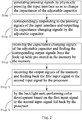
- the input device comprises an input interface 10, an adjustable capacitor 20, a memory 30, a processor 40 and a backlight unit 50.
- the input interface 10 is in direct contact with an input operator; and pressing signals are generated when the input interface 10 is physically pressed and the delivered pressing force moves up and down in the vertical direction along with the pressing effect of the input operator.
- the adjustable capacitor 20 is abutted with the lower end of the input interface 10; and the capacitance of the capacitor 20 changes after the capacitor 20 is subjected to the pressing force of the input interface 10.
- the adjustable capacitor 20 correspondingly responds to the pressing signals of the input interface 10 and outputs the capacitance changing signals.
- the memory 30 is electrically connected with the adjustable capacitor 20 and the processor 40, respectively.
- a look-up table is pre-stored in the memory 30 and the memory 30 receives the capacitance value changing signals of the adjustable capacitor 20 and correspondingly finds the corresponding output signals from the look-up table.
- the capacitance value changing signals in a certain range can be set to correspond to an output signal, for example, if [delta]C is greater than or equal to 0 but less than or equal to IF, the corresponding output signal is zero; and if the [delta]C is greater than or equal to IF but less than or equal to 2F, the corresponding output signal is 1; and [delta]C is the capacitance changing value of the adjustable capacitor 20.
- one capacitance changing value also can be set to correspond to one output signal.
- the processor 40 receives the output signals of the memory 30 and feeds back a first input signal or a second input signal, that is, it judges whether the output signals of the memory 30 are effective output signals. In the embodiment, when the output signals is set as zero, the processor 40 feeds back the first input signal, that is, no input signal is generated, and the input of the input device is invalid; when the output signal is set as 1, the processor 40 feeds back the second input signal, that is, the input signal is generated, and the input of the input device is effective.
- the backlight unit 50 is electrically connected with the processor 40.
- the backlight unit 50 performs color development based on the first input signal or the second input signal fed back by the processor 40. In the embodiment, when the processor 40 feeds back the first input signal, the backlight unit 50 does not perform the color development, and when the processor 40 feeds back the second input signal, the backlight unit 50 performs the color development to remind the input operator that the input operation is an effective input.
- the processor 40 also can be electrically connected with an external output end (not shown in the Fig.).
- the external output end outputs its signal based on the first input signal or the second input signal fed back by the processor 40.
- the external output end can be a personal computer or a mobile phone.
- the input operation method comprises the following steps:
- the capacitance value generally represents the ability thereof of containing electric charges.
- the capacitance value C of the capacitor is equal to [epsilon]S/4[pi]kd, wherein d is the distance between polar plates, S is the direct-facing area of each polar plate, [epsilon] is a dielectric constant, and k is an electrostatic constant. Therefore, in step S1, the main factors for the change of the capacitance of the adjustable capacitor 20 are the distance d between the polar plates and the direct-facing area S of each polar plate.
- the input operation method of the input device will be described simply below from the above two factors.
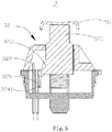
- the input device 1 comprises an input interface 11, an adjustable capacitor 12, a memory (not shown in the Fig.), a processor (not shown in the Fig.) and a backlight unit (not shown in the Fig.).
- the input interface 11 is in direct contact with the input operator; and pressing signals are generated when the input interface 11 is physically pressed and the delivered pressing force moves up and down in the vertical direction along with the pressing effect of the input operator.
- the adjustable capacitor 12 comprises a lead column 121, an elastic body 122, a frame 123, a first polar plate 124, a second polar plate 125 and a conducting circuit 126.
- the whole lead column 121 is a long column, one end thereof is abutted with the inner surface of the input interface 11 while the other end thereof is suspended and is contained in the frame 123.
- the lead column 121 comprises a bulge 1211.
- the bulge 1211 is formed by extending the side surface of the lead column 121 and is arranged at the intermediate height position of the lead column 121.
- the bulge 1211 and the lead column 121 can be of an integral structure, and the bulge 1211 also can be an independent component of the lead column 121.
- the elastic body 122 is a stainless steel spring sleeved at the outside of the lead column 121.
- the frame 123 supports one end of the elastic body 122 while the other end of the elastic body 122 is abutted with the lead column 121; that is to say, the elastic body 122 is clamped between the frame 123 and the lead column 121.
- the elastic body 122 When the lead column 121, under the action of the input interface 11, moves towards the frame 123, the elastic body 122 is driven to be in a compressed state; when the acting force applied to the lead column 121 disappears, the elastic body 122 drives the lead column 121 to move far away from the frame 123 under the action of the elastic deformation thereof; that is to say, the lead column 121 performs a reciprocating motion with respect to the frame 123.
- the frame 123 comprises an insulator 1231; and the insulator 1231 is formed by extending the bottom plate of the frame 123.
- the first polar plate 124 and the second polar plate 125 are arranged oppositely in a coupling manner and at intervals.
- One end of the first polar plate 124 and one end of the second polar plate 125 are respectively fixed at the frame 123; the other ends thereof are respectively arranged in a manner of extending far away from the frame 123; and the insulator 1231 of the frame 123 is clamped between the first polar plate 124 and the second polar plate 125.
- the second polar plate 125 comprises abutting ends 1251.
- the abutting ends 1251 are formed by extending from one end of the second polar plate to the side far away from the first polar plate 124 and are elastically butted with the bulge 1211 of the lead column 121.
- the first polar plate 124 is fixedly arranged with respect to the lead column 121; and the second polar plate 125 is clamped between the first polar plate 124 and the lead column 121.
- the conducting circuit 126 is a wire used for transmitting the capacitance changing signals of the adjustable capacitor 12; one end of the conducting circuit 126 is respectively connected with one end of the first polar plate 124 and one end of the second polar plate 125; and the other end is correspondingly connected with the memory.
- the memory is electrically connected with the adjustable capacitor 12 and the processor, respectively; and the backlight unit is electrically connected with the processor.
- the input operation method of the input device 1 comprises the following steps:
- the projection of the first polar plate 124 is always in the plane where the second polar plate 125 is; that is to say, when the second polar plate 125 moves rotationally, the relative area S between the first polar plate 124 and the second polar plate 125 is unchanged, and the capacitance C of the adjustable capacitor 12 changes correspondingly along with the distance d between the first polar plate 124 and the second polar plate 125. Therefore, the change of the capacitance value is realized, and the capacitance changing signals are output.
- Fig. 4 a profile section view of the embodiment 2 of the input device shown in the Fig. 1 .
- the height of the second polar plate 225 is smaller than that of the first polar plate 224, and the first polar plate 224 comprises the abutting ends 2241.
- the abutting ends 2241 are formed by extending from one end of the first polar plate 224.
- the second polar plate 225 comprises a nick (not shown in the Fig.); the nick is of a hollow structure formed at the middle part of the second polar plate 225.
- Each abutting end 2241 penetrates the nick of the second polar plate 225 and is arranged in a way of extending towards the lead column 221.
- the second polar plate 225 is clamped between the first polar plate 224 and the lead column 221 and is arranged fixedly with respect to the lead column 221; and each abutting end 2241 is elastically abutted with the bulge 2211 of the lead column 221.
- the input operation method of the input device 2 comprises the following steps:
- the relative area S between the second polar plate 225 and the first polar plate 224 is unchanged when the first polar plate 224 moves rotationally, and the capacitance C of the adjustable capacitor 22 changes correspondingly along with the distance d between the first polar plate 224 and the second polar plate 225. Therefore, the change of the capacitance value is realized, and the capacitance changing signals are output.
- the input device 3 comprises an input interface 31, an adjustable capacitor 32, a memory (not shown in the Fig.), a processor (not shown in the Fig.) and a backlight unit (not shown in the Fig.).
- the first polar plate 324 comprises two symmetrically arranged abutting ends 3241.
- the abutting ends 3241 are formed by extending the middle part of the first polar plate 324.
- the second polar plate 325 comprises a nick (not shown in the Fig.); the nick is of a hollow structure formed at the middle part of the second polar plate 325.
- Each abutting end 3241 penetrates the nick of the second polar plate 325 and is arranged to extend towards the lead column 321.
- the second polar plate 325 is clamped between the first polar plate 324 and the lead column 321 and is arranged fixedly with respect to the lead column 321; and the abutting ends 3241 are elastically abutted with the bulge 3211 of the lead column 321.
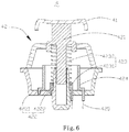
- the input device 4 comprises an input interface 41, an adjustable capacitor 42, a memory (not shown in the Fig.), a processor (not shown in the Fig.) and a backlight unit (not shown in the Fig.).
- the input interface 41 is in direct contact with the input operator; and pressing signals are generated when the input interface 41 is physically pressed and the delivered pressing force moves up and down in the vertical direction along with the pressing effect of the input operator.
- the adjustable capacitor 42 comprises a lead column 421, a frame 422, a polar plate 423, a second polar plate 424 and a conducting circuit 425.
- the whole lead column 421 is a long column, one end thereof is abutted with the inner surface of the input interface 41 while the other end thereof is suspended and is contained in the frame 422.
- the frame 422 comprises a bottom plate 4221 and a hollow lead tube 4222.
- the lead tube 4222 is arranged at the center of the bottom plate 422.
- the lead column 421 is partially inserted into the lead tube 4222.
- the lead column 421 performs a reciprocating motion with respect to the frame 422.
- the first polar plate 423 and the second polar plate 424 are arranged oppositely in a coupling manner and at intervals on the frame 422.
- the first polar plate 423 comprises a main body part 4231 and an elastic body 4232.
- the main body part 4231 and the second polar plate 424 are the same in structure and are hollow cylinders; and the outer diameter of the main body part 4231 is smaller than the inner diameter of the second polar plate 424, and the height of the main body part 4231 is smaller than that of the second polar plate 424.
- the main body part 4231 is tightly sleeved at the outside of the lead tube 4222 and is fixed with the bottom plate 4221; the second polar plate 424 is also sleeve at the outside of the lead tube 4222, but has a certain distance to the main body part 4231; and the lower end of the second polar plate 424 is fixed at the bottom plate 4221 of the frame 422.
- the top end of the main body part 4231 is provided with a groove (without label).
- the elastic body 4232 is a stainless steel spring sleeved at the outsides of both the lead column 421 and the lead tube 4222; and the upper end of the spring is abutted with the lead column 421 while the lower end thereof is clamped in the groove of the main body part 4231 so as to be tightly connected with the main body part 4231.
- the elastic body 4232 is fixedly connected with the main body part 4231 to form the first polar plate 423 which is arranged to be coupled with the second polar plate 424 at intervals.
- the conducting circuit 425 is a wire used for transmitting the capacitance changing signals of the adjustable capacitor 42; one end of the conducting circuit 425 is respectively connected with one end of the first polar plate 423 and one end of the second polar plate 424; and the other end of the conducting circuit 425 is correspondingly connected with the memory.
- the memory is electrically connected with the adjustable capacitor 42 and the processor, respectively; and the backlight unit is electrically connected with the processor.
- the input operation method of the input device 4 comprises the following steps:
- the capacitance C of the adjustable capacitor 42 changes correspondingly along with the direct-facing area S between the first polar plate 423 and the second polar plate 424. Therefore, the change of the capacitance value is realized, and the capacitance changing signals are output.
Landscapes
- Engineering & Computer Science (AREA)
- General Engineering & Computer Science (AREA)
- Theoretical Computer Science (AREA)
- Human Computer Interaction (AREA)
- Physics & Mathematics (AREA)
- General Physics & Mathematics (AREA)
- Input From Keyboards Or The Like (AREA)
- Switches That Are Operated By Magnetic Or Electric Fields (AREA)
Applications Claiming Priority (6)
| Application Number | Priority Date | Filing Date | Title |
|---|---|---|---|
| CN201520037259.3U CN204465500U (zh) | 2015-01-19 | 2015-01-19 | 电容感应按键开关及采用所述电容感应按键开关的键盘 |
| CN201510027012.8A CN104571766B (zh) | 2015-01-19 | 2015-01-19 | 输入装置的输入操作方法 |
| CN201520036718.6U CN204537912U (zh) | 2015-01-19 | 2015-01-19 | 电容感应按键开关及采用所述按键开关的键盘 |
| CN201520036774.XU CN204465499U (zh) | 2015-01-19 | 2015-01-19 | 电容感应按键开关及采用所述电容感应按键开关的键盘 |
| CN201520036833.3U CN204539114U (zh) | 2015-01-19 | 2015-01-19 | 电容式按键单元及采用所述按键单元的键盘 |
| PCT/CN2015/096503 WO2016115946A1 (zh) | 2015-01-19 | 2015-12-06 | 输入装置及其输入操作方法 |
Publications (4)
| Publication Number | Publication Date |
|---|---|
| EP3249507A1 true EP3249507A1 (de) | 2017-11-29 |
| EP3249507A4 EP3249507A4 (de) | 2018-10-31 |
| EP3249507B1 EP3249507B1 (de) | 2024-02-14 |
| EP3249507C0 EP3249507C0 (de) | 2024-02-14 |
Family
ID=56416395
Family Applications (1)
| Application Number | Title | Priority Date | Filing Date |
|---|---|---|---|
| EP15878614.5A Active EP3249507B1 (de) | 2015-01-19 | 2015-12-06 | Eingabevorrichtung und eingabebetriebsverfahren dafür |
Country Status (4)
| Country | Link |
|---|---|
| US (1) | US10312909B2 (de) |
| EP (1) | EP3249507B1 (de) |
| KR (1) | KR102066523B1 (de) |
| WO (1) | WO2016115946A1 (de) |
Families Citing this family (1)
| Publication number | Priority date | Publication date | Assignee | Title |
|---|---|---|---|---|
| CN110531190A (zh) * | 2019-08-19 | 2019-12-03 | 深圳市力驰创新科技有限公司 | 输入系统的检测方法 |
Family Cites Families (18)
| Publication number | Priority date | Publication date | Assignee | Title |
|---|---|---|---|---|
| US4090229A (en) * | 1976-09-30 | 1978-05-16 | Becton, Dickinson Electronics Company | Capacitive key for keyboard |
| US4325102A (en) * | 1980-10-10 | 1982-04-13 | General Instrument Corporation | Variable capacitor for use in a keyboard |
| US4849852A (en) * | 1988-09-30 | 1989-07-18 | Alps Electric (U.S.A.), Inc. | Variable capacitance push-button switch |
| JP4284271B2 (ja) * | 2004-12-22 | 2009-06-24 | アップサイド株式会社 | データ入力装置、データ入力方法ならびにデータ入力プログラムおよびこれを記録した記録媒体 |
| US20080196945A1 (en) * | 2007-02-21 | 2008-08-21 | Jason Konstas | Preventing unintentional activation of a sensor element of a sensing device |
| JP4646340B2 (ja) * | 2008-09-03 | 2011-03-09 | 昌徳 水島 | 入力装置 |
| US8436816B2 (en) * | 2008-10-24 | 2013-05-07 | Apple Inc. | Disappearing button or slider |
| US8711011B2 (en) * | 2008-12-16 | 2014-04-29 | Dell Products, Lp | Systems and methods for implementing pressure sensitive keyboards |
| US8018238B2 (en) * | 2009-03-27 | 2011-09-13 | Texas Instruments Incorporated | Embedded sar based active gain capacitance measurement system and method |
| US8912458B2 (en) * | 2011-01-04 | 2014-12-16 | Synaptics Incorporated | Touchsurface with level and planar translational travel responsiveness |
| CN202394179U (zh) * | 2011-06-28 | 2012-08-22 | 幻音科技(深圳)有限公司 | 输入装置 |
| CN102981663A (zh) * | 2011-09-06 | 2013-03-20 | 昆盈企业股份有限公司 | 驻极体输入装置及其操作方法 |
| US20140354577A1 (en) * | 2013-05-28 | 2014-12-04 | Ingar Hanssen | Multi-State Capacitive Button |
| CN204539114U (zh) * | 2015-01-19 | 2015-08-05 | 黄俭安 | 电容式按键单元及采用所述按键单元的键盘 |
| CN204465500U (zh) * | 2015-01-19 | 2015-07-08 | 黄俭安 | 电容感应按键开关及采用所述电容感应按键开关的键盘 |
| CN204465499U (zh) * | 2015-01-19 | 2015-07-08 | 黄俭安 | 电容感应按键开关及采用所述电容感应按键开关的键盘 |
| CN104571766B (zh) * | 2015-01-19 | 2019-11-19 | 深圳市力驰创新科技有限公司 | 输入装置的输入操作方法 |
| CN204537912U (zh) * | 2015-01-19 | 2015-08-05 | 黄俭安 | 电容感应按键开关及采用所述按键开关的键盘 |
-
2015
- 2015-12-06 KR KR1020177021457A patent/KR102066523B1/ko active IP Right Grant
- 2015-12-06 EP EP15878614.5A patent/EP3249507B1/de active Active
- 2015-12-06 WO PCT/CN2015/096503 patent/WO2016115946A1/zh active Application Filing
- 2015-12-06 US US15/544,026 patent/US10312909B2/en active Active
Also Published As
| Publication number | Publication date |
|---|---|
| US20180006649A1 (en) | 2018-01-04 |
| WO2016115946A1 (zh) | 2016-07-28 |
| KR102066523B1 (ko) | 2020-01-15 |
| US10312909B2 (en) | 2019-06-04 |
| EP3249507A4 (de) | 2018-10-31 |
| KR20170123310A (ko) | 2017-11-07 |
| EP3249507B1 (de) | 2024-02-14 |
| EP3249507C0 (de) | 2024-02-14 |
Similar Documents
| Publication | Publication Date | Title |
|---|---|---|
| CN108845724B (zh) | 具有防止误触功能的电容式按键模块 | |
| CN1169335C (zh) | 输入装置 | |
| US11892703B2 (en) | Haptic feedback system | |
| CN106909244B (zh) | 触控按键、触控操作检测方法、触控ic及电子设备 | |
| CN108900185A (zh) | 一种电容触摸开关及其应用的电子设备 | |
| CN110134254B (zh) | 终端控制系统及方法 | |
| JP6122192B2 (ja) | 電子機器 | |
| US10312909B2 (en) | Input device and input operation method thereof | |
| CN204465499U (zh) | 电容感应按键开关及采用所述电容感应按键开关的键盘 | |
| CN104571766B (zh) | 输入装置的输入操作方法 | |
| CN204537912U (zh) | 电容感应按键开关及采用所述按键开关的键盘 | |
| CN104579294A (zh) | 电容式按键单元及采用所述按键单元的键盘 | |
| CN217847096U (zh) | 一种输入信号产生装置及电子设备 | |
| US11989378B2 (en) | Passive pen with variable capacitor for pressure indication | |
| CN207966814U (zh) | 用于触控屏的按键结构、触控屏及销售点终端 | |
| CN115097954A (zh) | 一种输入信号产生装置及电子设备 | |
| CN204539113U (zh) | 电容式按键单元及采用所述按键单元的键盘 | |
| WO2012102049A1 (ja) | 電子機器 | |
| CN206271593U (zh) | 一种按键及电子设备 | |
| CN204087155U (zh) | 触控键盘 | |
| CN211557245U (zh) | 键盘 | |
| CN220874524U (zh) | 触压感应模组、耳机及电子装置 | |
| JP4202711B2 (ja) | リニアスイッチ | |
| CN220872989U (zh) | 触压感应模组、耳机及电子装置 | |
| CN218413347U (zh) | 电子设备 |
Legal Events
| Date | Code | Title | Description |
|---|---|---|---|
| STAA | Information on the status of an ep patent application or granted ep patent |
Free format text: STATUS: THE INTERNATIONAL PUBLICATION HAS BEEN MADE |
|
| PUAI | Public reference made under article 153(3) epc to a published international application that has entered the european phase |
Free format text: ORIGINAL CODE: 0009012 |
|
| STAA | Information on the status of an ep patent application or granted ep patent |
Free format text: STATUS: REQUEST FOR EXAMINATION WAS MADE |
|
| 17P | Request for examination filed |
Effective date: 20170818 |
|
| AK | Designated contracting states |
Kind code of ref document: A1 Designated state(s): AL AT BE BG CH CY CZ DE DK EE ES FI FR GB GR HR HU IE IS IT LI LT LU LV MC MK MT NL NO PL PT RO RS SE SI SK SM TR |
|
| AX | Request for extension of the european patent |
Extension state: BA ME |
|
| DAV | Request for validation of the european patent (deleted) | ||
| DAX | Request for extension of the european patent (deleted) | ||
| RIC1 | Information provided on ipc code assigned before grant |
Ipc: G06F 3/02 20060101AFI20180620BHEP Ipc: H03K 17/967 20060101ALI20180620BHEP Ipc: H03K 17/98 20060101ALI20180620BHEP Ipc: H03K 17/96 20060101ALI20180620BHEP Ipc: H03K 17/965 20060101ALI20180620BHEP Ipc: H03K 17/975 20060101ALI20180620BHEP |
|
| STAA | Information on the status of an ep patent application or granted ep patent |
Free format text: STATUS: EXAMINATION IS IN PROGRESS |
|
| A4 | Supplementary search report drawn up and despatched |
Effective date: 20181001 |
|
| RIC1 | Information provided on ipc code assigned before grant |
Ipc: H03K 17/965 20060101ALI20180925BHEP Ipc: H03K 17/975 20060101ALI20180925BHEP Ipc: H03K 17/96 20060101ALI20180925BHEP Ipc: G06F 3/02 20060101AFI20180925BHEP Ipc: H03K 17/98 20060101ALI20180925BHEP Ipc: H03K 17/967 20060101ALI20180925BHEP |
|
| 17Q | First examination report despatched |
Effective date: 20181019 |
|
| 17Q | First examination report despatched |
Effective date: 20181211 |
|
| 17Q | First examination report despatched |
Effective date: 20181213 |
|
| RIC1 | Information provided on ipc code assigned before grant |
Ipc: H03K 17/98 20060101ALI20181210BHEP Ipc: H03K 17/967 20060101ALI20181210BHEP Ipc: G06F 3/02 20060101AFI20181210BHEP Ipc: H03K 17/96 20060101ALI20181210BHEP Ipc: H03K 17/965 20060101ALI20181210BHEP Ipc: H03K 17/975 20060101ALI20181210BHEP |
|
| STAA | Information on the status of an ep patent application or granted ep patent |
Free format text: STATUS: EXAMINATION IS IN PROGRESS |
|
| STAA | Information on the status of an ep patent application or granted ep patent |
Free format text: STATUS: EXAMINATION IS IN PROGRESS |
|
| GRAP | Despatch of communication of intention to grant a patent |
Free format text: ORIGINAL CODE: EPIDOSNIGR1 |
|
| STAA | Information on the status of an ep patent application or granted ep patent |
Free format text: STATUS: GRANT OF PATENT IS INTENDED |
|
| RIC1 | Information provided on ipc code assigned before grant |
Ipc: G06F 3/044 20060101ALI20230724BHEP Ipc: H03K 17/975 20060101ALI20230724BHEP Ipc: G06F 3/02 20060101AFI20230724BHEP |
|
| INTG | Intention to grant announced |
Effective date: 20230829 |
|
| GRAS | Grant fee paid |
Free format text: ORIGINAL CODE: EPIDOSNIGR3 |
|
| GRAA | (expected) grant |
Free format text: ORIGINAL CODE: 0009210 |
|
| STAA | Information on the status of an ep patent application or granted ep patent |
Free format text: STATUS: THE PATENT HAS BEEN GRANTED |
|
| AK | Designated contracting states |
Kind code of ref document: B1 Designated state(s): AL AT BE BG CH CY CZ DE DK EE ES FI FR GB GR HR HU IE IS IT LI LT LU LV MC MK MT NL NO PL PT RO RS SE SI SK SM TR |
|
| REG | Reference to a national code |
Ref country code: GB Ref legal event code: FG4D |
|
| REG | Reference to a national code |
Ref country code: CH Ref legal event code: EP |
|
| REG | Reference to a national code |
Ref country code: DE Ref legal event code: R096 Ref document number: 602015087567 Country of ref document: DE |
|
| REG | Reference to a national code |
Ref country code: IE Ref legal event code: FG4D |
|
| U01 | Request for unitary effect filed |
Effective date: 20240214 |
|
| U07 | Unitary effect registered |
Designated state(s): AT BE BG DE DK EE FI FR IT LT LU LV MT NL PT SE SI Effective date: 20240223 |