EP3249450B1 - Substrate, grating and display panel - Google Patents
Substrate, grating and display panel Download PDFInfo
- Publication number
- EP3249450B1 EP3249450B1 EP15839118.5A EP15839118A EP3249450B1 EP 3249450 B1 EP3249450 B1 EP 3249450B1 EP 15839118 A EP15839118 A EP 15839118A EP 3249450 B1 EP3249450 B1 EP 3249450B1
- Authority
- EP
- European Patent Office
- Prior art keywords
- sub
- pixel
- pixel unit
- grating
- column
- Prior art date
- Legal status (The legal status is an assumption and is not a legal conclusion. Google has not performed a legal analysis and makes no representation as to the accuracy of the status listed.)
- Active
Links
Images


Classifications
-
- G—PHYSICS
- G02—OPTICS
- G02F—OPTICAL DEVICES OR ARRANGEMENTS FOR THE CONTROL OF LIGHT BY MODIFICATION OF THE OPTICAL PROPERTIES OF THE MEDIA OF THE ELEMENTS INVOLVED THEREIN; NON-LINEAR OPTICS; FREQUENCY-CHANGING OF LIGHT; OPTICAL LOGIC ELEMENTS; OPTICAL ANALOGUE/DIGITAL CONVERTERS
- G02F1/00—Devices or arrangements for the control of the intensity, colour, phase, polarisation or direction of light arriving from an independent light source, e.g. switching, gating or modulating; Non-linear optics
- G02F1/01—Devices or arrangements for the control of the intensity, colour, phase, polarisation or direction of light arriving from an independent light source, e.g. switching, gating or modulating; Non-linear optics for the control of the intensity, phase, polarisation or colour
- G02F1/13—Devices or arrangements for the control of the intensity, colour, phase, polarisation or direction of light arriving from an independent light source, e.g. switching, gating or modulating; Non-linear optics for the control of the intensity, phase, polarisation or colour based on liquid crystals, e.g. single liquid crystal display cells
- G02F1/133—Constructional arrangements; Operation of liquid crystal cells; Circuit arrangements
- G02F1/1333—Constructional arrangements; Manufacturing methods
- G02F1/1335—Structural association of cells with optical devices, e.g. polarisers or reflectors
- G02F1/133509—Filters, e.g. light shielding masks
- G02F1/133514—Colour filters
-
- G—PHYSICS
- G02—OPTICS
- G02B—OPTICAL ELEMENTS, SYSTEMS OR APPARATUS
- G02B30/00—Optical systems or apparatus for producing three-dimensional [3D] effects, e.g. stereoscopic images
- G02B30/20—Optical systems or apparatus for producing three-dimensional [3D] effects, e.g. stereoscopic images by providing first and second parallax images to an observer's left and right eyes
- G02B30/26—Optical systems or apparatus for producing three-dimensional [3D] effects, e.g. stereoscopic images by providing first and second parallax images to an observer's left and right eyes of the autostereoscopic type
- G02B30/27—Optical systems or apparatus for producing three-dimensional [3D] effects, e.g. stereoscopic images by providing first and second parallax images to an observer's left and right eyes of the autostereoscopic type involving lenticular arrays
-
- G—PHYSICS
- G02—OPTICS
- G02F—OPTICAL DEVICES OR ARRANGEMENTS FOR THE CONTROL OF LIGHT BY MODIFICATION OF THE OPTICAL PROPERTIES OF THE MEDIA OF THE ELEMENTS INVOLVED THEREIN; NON-LINEAR OPTICS; FREQUENCY-CHANGING OF LIGHT; OPTICAL LOGIC ELEMENTS; OPTICAL ANALOGUE/DIGITAL CONVERTERS
- G02F1/00—Devices or arrangements for the control of the intensity, colour, phase, polarisation or direction of light arriving from an independent light source, e.g. switching, gating or modulating; Non-linear optics
- G02F1/01—Devices or arrangements for the control of the intensity, colour, phase, polarisation or direction of light arriving from an independent light source, e.g. switching, gating or modulating; Non-linear optics for the control of the intensity, phase, polarisation or colour
- G02F1/13—Devices or arrangements for the control of the intensity, colour, phase, polarisation or direction of light arriving from an independent light source, e.g. switching, gating or modulating; Non-linear optics for the control of the intensity, phase, polarisation or colour based on liquid crystals, e.g. single liquid crystal display cells
- G02F1/133—Constructional arrangements; Operation of liquid crystal cells; Circuit arrangements
- G02F1/1333—Constructional arrangements; Manufacturing methods
- G02F1/1335—Structural association of cells with optical devices, e.g. polarisers or reflectors
- G02F1/133504—Diffusing, scattering, diffracting elements
-
- G—PHYSICS
- G09—EDUCATION; CRYPTOGRAPHY; DISPLAY; ADVERTISING; SEALS
- G09F—DISPLAYING; ADVERTISING; SIGNS; LABELS OR NAME-PLATES; SEALS
- G09F9/00—Indicating arrangements for variable information in which the information is built-up on a support by selection or combination of individual elements
- G09F9/30—Indicating arrangements for variable information in which the information is built-up on a support by selection or combination of individual elements in which the desired character or characters are formed by combining individual elements
- G09F9/313—Indicating arrangements for variable information in which the information is built-up on a support by selection or combination of individual elements in which the desired character or characters are formed by combining individual elements being gas discharge devices
-
- H—ELECTRICITY
- H04—ELECTRIC COMMUNICATION TECHNIQUE
- H04N—PICTORIAL COMMUNICATION, e.g. TELEVISION
- H04N13/00—Stereoscopic video systems; Multi-view video systems; Details thereof
- H04N13/30—Image reproducers
- H04N13/302—Image reproducers for viewing without the aid of special glasses, i.e. using autostereoscopic displays
- H04N13/305—Image reproducers for viewing without the aid of special glasses, i.e. using autostereoscopic displays using lenticular lenses, e.g. arrangements of cylindrical lenses
-
- H—ELECTRICITY
- H04—ELECTRIC COMMUNICATION TECHNIQUE
- H04N—PICTORIAL COMMUNICATION, e.g. TELEVISION
- H04N13/00—Stereoscopic video systems; Multi-view video systems; Details thereof
- H04N13/30—Image reproducers
- H04N13/302—Image reproducers for viewing without the aid of special glasses, i.e. using autostereoscopic displays
- H04N13/31—Image reproducers for viewing without the aid of special glasses, i.e. using autostereoscopic displays using parallax barriers
-
- H—ELECTRICITY
- H04—ELECTRIC COMMUNICATION TECHNIQUE
- H04N—PICTORIAL COMMUNICATION, e.g. TELEVISION
- H04N13/00—Stereoscopic video systems; Multi-view video systems; Details thereof
- H04N13/30—Image reproducers
- H04N13/324—Colour aspects
-
- H—ELECTRICITY
- H04—ELECTRIC COMMUNICATION TECHNIQUE
- H04N—PICTORIAL COMMUNICATION, e.g. TELEVISION
- H04N13/00—Stereoscopic video systems; Multi-view video systems; Details thereof
- H04N13/30—Image reproducers
- H04N13/349—Multi-view displays for displaying three or more geometrical viewpoints without viewer tracking
- H04N13/351—Multi-view displays for displaying three or more geometrical viewpoints without viewer tracking for displaying simultaneously
-
- G—PHYSICS
- G02—OPTICS
- G02F—OPTICAL DEVICES OR ARRANGEMENTS FOR THE CONTROL OF LIGHT BY MODIFICATION OF THE OPTICAL PROPERTIES OF THE MEDIA OF THE ELEMENTS INVOLVED THEREIN; NON-LINEAR OPTICS; FREQUENCY-CHANGING OF LIGHT; OPTICAL LOGIC ELEMENTS; OPTICAL ANALOGUE/DIGITAL CONVERTERS
- G02F2201/00—Constructional arrangements not provided for in groups G02F1/00 - G02F7/00
- G02F2201/52—RGB geometrical arrangements
Description
- Embodiments of the present disclosure relate to a system comprising a grating and a substrate and to a display panel.
- With the popularity of a touch tablet computer, a user requirement on a display is getting higher and higher. A part of current tablet computers can realize naked-eye stereoscopic display. For example, a viewpoint image displayed by each
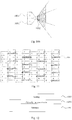
sub-pixel column 101 enters a human's eye through agrating 102. But, as illustrated inFIG. 1 , a first viewpoint image displayed by a first sub-pixel column can be seen in a first viewing angle region, which is a gray shaded region defined by a line A11 and a line A12, a second viewpoint image displayed by a second sub-pixel column can be seen in a second viewing angle region, which is a display region marked with dots and defined by a line A21 and a line A22, and a third viewpoint image displayed by a third sub-pixel column can be seen in a third viewing angle region, which is a region marked with vertical lines and defined by a line A31 and a line A31. InFIG. 1, 1 stands for a first sub-pixel unit, 2 stands for a second sub-pixel unit, 3 stands for a third sub-pixel unit; however, because the first viewing angle region, the second viewing angle region and the third viewing angle region are very close to each other, and the viewing angle range is limited within the range of 180 degrees, the interference occurs between the viewpoint images, and it can not be achieved that multiple persons view one display.
EP 0 752 610 A1 discloses that a liquid crystal spatial light modulator comprises columns and rows of picture elements (24-26). The columns are arranged as groups of columns, for instance under respective parallax generating elements in an autostereoscopic 3D display. The picture elements (24-26) are arranged as sets to form colour picture elements such that the picture elements (24-26) of each set are disposed at the apices of a polygon, such as a triangle (21), and are disposed in corresponding columns of the groups of columns.US 2005/083246 A1 discloses a stereoscopic display device and a display method, which is made possible to satisfy such a condition that moire or color moire is suppressed and a fast image processing is made easy and such a condition that sufficient image quality can be obtained both at a flat image display time and at a stereoscopic image display time simultaneously. A vertical period of pixel rows having the pixels arranged in one row in a lateral direction is three times a lateral period of the pixels, the pixels developing red, green and blue are alternately arranged in a lateral direction in the same row, the pixels in one row of two rows adjacent in a vertical direction are arranged such that lateral positions thereof are shifted to the pixels in the other row by 1/2 of the lateral period of the pixels, the pixels in rows adjacent in the same column through one row interposed therebetween are the pixels developing different colors of red, green and blue, and a pitch of the elemental images is equal to a width of 18n (n=1,2, 3 ... ) pieces of the pixels, and a lateral pitch of the beam control element is smaller than the width of the 18n pieces of the pixels. - Embodiments of the present disclosure provide a system comprising a grating and a substrate and provide a display panel, which is capable of increasing the viewing angle of each viewpoint image through the arrangement of the sub-pixel units on the substrate, and reducing the interference between different viewpoint images, because within each viewing angle, only the viewpoint image corresponding to the viewing angle can be seen.
- In an aspect, an embodiment of the present disclosure provides a system comprising a grating and a substrate wherein the substrate comprises a plurality of sub-pixel groups arranged periodically, wherein each of the plurality of sub-pixel groups comprises: a first type of sub-pixel group which is configured for displaying a plurality of viewpoint images and comprises a first sub-pixel unit configured for displaying a first viewpoint image, a second sub-pixel unit configured for displaying a second viewpoint image and a third sub-pixel unit configured for displaying a third viewpoint image; each of the plurality of sub-pixel groups at least comprises a first sub-pixel column and a second sub-pixel columns; and the first sub-pixel unit is located in the first sub-pixel column of each of the plurality of sub-pixel groups, the second sub-pixel unit and the third sub-pixel unit are located in the second sub-pixel column of each of the plurality of sub-pixel groups, the second sub-pixel column and the first sub-pixel column are adjacent to each other and are staggered a preset distance in a vertical direction, and the preset distance is smaller than a width of one sub-pixel unit, the first sub-pixel unit, the second sub-pixel unit and the third sub-pixel unit are adjacent to each other, wherein
an opening region of the grating corresponds to the first type of sub-pixel group, and a shape of the opening region of the grating is: a shape formed by a triangle and a quadrilateral, with a side of the triangle coinciding with a side of the quadrilateral; or, a shape formed by two triangles, with a vertex of one of the triangles coinciding with a side of the other one of the triangles. - An embodiment of the present disclosure provides a display panel, and the display panel includes the above-mentioned system.
- In order to clearly illustrate the technical solution of the embodiments of the invention, the drawings of the embodiments will be briefly described in the following; it is obvious that the described drawings are only related to some embodiments of the invention and thus are not limitative of the invention.
-
FIG. 1 is a schematic view of viewing angles of a substrate provided in a current multi-view display technology; -
FIG. 2 is a structural schematic view of sub-pixel units corresponding to a substrate provided by a first embodiment of the present disclosure; -
FIG. 3a is a structural schematic view of sub-pixel units corresponding to a substrate provided by the first embodiment of the present disclosure, upon a second type of sub-pixel unit being a black sub-pixel unit; -
FIG. 3b is a structural schematic view of sub-pixel units corresponding to a substrate provided by the first embodiment of the present disclosure, upon the second type of sub-pixel unit being a white sub-pixel unit; -
FIG. 4 is a structural substrate of a substrate provided by the first embodiment of the present disclosure; -
FIG. 5a is a structural schematic view of a first viewing angle region of a substrate provided by the first embodiment of the present disclosure; -
FIG. 5b is a structural schematic view of a second viewing angle region and a third viewing angle region of the substrate provided by the first embodiment of the present disclosure; -
FIG. 6 is a structural schematic view of a grating corresponding to a substrate provided by the first embodiment of the present disclosure; -
FIG. 7 is a structural schematic view of another grating corresponding to a substrate provided by the first embodiment of the present disclosure; -
FIG. 8 is a structural schematic view of sub-pixel units corresponding to a substrate provided by a second embodiment of the present disclosure; -
FIG. 9 is a structural schematic view of a substrate provided by the second embodiment of the present disclosure; -
FIG. 10a is a structural schematic view of a first viewing angle region and a third viewing angle region of a substrate provided by the second embodiment of the present disclosure; -
FIG. 10b is a structural schematic view of a second viewing angle region and a fourth viewing angle region of the substrate provided by the second embodiment of the present disclosure; -
FIG. 11 is a structural schematic view of a grating corresponding to a substrate provided by the second embodiment of the present disclosure; and -
FIG. 12 is a sectional schematic view of a display panel provided by an embodiment of the disclosure. - In order to make objects, technical details and advantages of the embodiments of the invention apparent, the technical solutions of the embodiment will be described in a clearly and fully understandable way in connection with the drawings related to the embodiments of the invention. It is obvious that the described embodiments are just a part but not all of the embodiments of the invention. Based on the described embodiments herein, those skilled in the art can obtain other embodiment(s), without any inventive work, which should be within the scope of the invention.
- Embodiments of the present disclosure provides a substrate, a grating and a display panel, by changing arrangement of sub-pixels on the substrate, the viewing angle of each viewpoint image is increased, and because within each viewing angle region, only the viewpoint image corresponding to the viewing angle region can be seen, it can not be affected by viewpoint images displayed by other viewing angle regions.
- The technical solutions in the embodiments will be described in a clearly and fully understandable way in connection with the drawings related to the embodiments of the disclosure. Apparently, the described embodiments are just a part but not all of the embodiments of the disclosure. Based on the described embodiments herein, those skilled in the art can obtain other embodiment(s), without any inventive work, which should be within the scope of the disclosure.
- An embodiment of the present disclosure provides a substrate including a plurality of sub-pixel groups arranged periodically, each sub-pixel group includes a plurality of sub-pixel units and each sub-pixel group includes a first type of sub-pixel group configured for displaying a plurality of viewpoint images.
- The substrate provided by an embodiment of the present disclosure will be explained below in conjunction with the accompanying drawings and implementations. As shown in the drawings, a
first sub-pixel unit 1, asecond sub-pixel unit 2, athird sub-pixel unit 3 and afourth sub-pixel unit 4 belong to the first type of sub-pixel unit, and a sub-pixel unit displaying a preset gray value, such as black or white, belong to a second type of sub-pixel unit. - Referring to
FIG. 2 , a first embodiment of the present disclosure provides a substrate, when each sub-pixel group in the substrate includes a plurality of a first type of sub-pixel groups for displaying a plurality of viewpoint images and each first type of sub-pixel group includes three first type of sub-pixel units, that is, the first type of sub-pixel groups each include: afirst sub-pixel unit 201 configured for displaying a first viewpoint image, asecond sub-pixel unit 202 configured for displaying a second viewpoint image and athird sub-pixel unit 203 configured for displaying a third viewpoint image, an exemplary arrangement of the first sub-pixel unit, the second sub-pixel unit and the third exemplary sub-pixel unit on the substrate is as follows. - The
first sub-pixel unit 201 is located in a first sub-pixel column, thesecond sub-pixel unit 202 and thethird sub-pixel unit 203 are located in a second sub-pixel column. - The
first sub-pixel unit 201 is adjacent to thesecond sub-pixel unit 202 and also adjacent to thethird sub-pixel unit 203. - As illustrated in
FIG. 2 , the first sub-pixel column is the sub-pixel column marked with oblique lines, and the second sub-pixel column is the sub-pixel column marked with horizontal lines. - The second sub-pixel column and the first sub-pixel column are adjacent to each other, and are staggered a preset distance d in a vertical direction, and the preset distance d is smaller than a width e of one sub-pixel unit.
- In order to increase the range of each viewing angle, the each sub-pixel group may also include: a second type of sub-pixel group configured for displaying a preset gray value. Referring to
Fig. 3a , when a second type of sub-pixel unit has a preset gray value of zero, i.e. when the second type of sub-pixel unit is ablack sub-pixel unit 301, the viewing angle of viewpoint image can be increased correspondingly; and referring toFig. 3b , when the second type of sub-pixel unit has a maximum preset gray value, i.e., when the second type of sub-pixel unit is awhite sub-pixel unit 302, the ambient light for viewing can be increased, and the energy loss can be reduced. - Exemplarily, referring to
Fig. 3a andFig. 3b , when the second type of sub-pixel group includes one second type of sub-pixel unit, i.e., a fifth sub-pixel unit, in each sub-pixel group, an exemplary arrangement of the first sub-pixel unit, the second sub-pixel unit, the third sub-pixel unit and the fifth sub-pixel unit on the substrate is as follows. - The first sub-pixel unit is located in the first sub-pixel column, the second sub-pixel unit and the third sub-pixel unit are located in the second sub-pixel column, and the fifth sub-pixel unit is located in the first sub-pixel column.
- The first sub-pixel unit is adjacent to the second sub-pixel unit and also adjacent to the third sub-pixel unit; and the fifth sub-pixel unit is adjacent to the first sub-pixel unit and also adjacent to the third sub-pixel unit.
- The arrangements, of the first sub-pixel unit, the second sub-pixel unit, the third sub-pixel unit and the fifth sub-pixel unit, provided by embodiments of the present disclosure are not limited to the arrangement illustrated in
Fig. 3a andFig. 3b . For example, the first type of sub-pixel groups may include a first sub-pixel group, a second sub-pixel group and a third sub-pixel group, the first sub-pixel group includes a plurality of the first sub-pixel units, the second sub-pixel group includes a plurality of the second sub-pixel units, the third sub-pixel group includes a plurality of the third sub-pixel units, the first sub-pixel group is located in the first sub-pixel column, the second sub-pixel group and the third sub-pixel group are located in the second sub-pixel column, the fifth sub-pixel unit is located in the first sub-pixel column; and the first sub-pixel group is adjacent to the second sub-pixel group, and is also adjacent to the third sub-pixel group. Alternatively, the second type of sub-pixel group includes a plurality of the second type of sub-pixel units, for example, when the second type of sub-pixel group includes a fifth sub-pixel unit and a sixth sub-pixel unit, the first sub-pixel unit and the fifth sub-pixel unit are located in the first sub-pixel column; the second sub-pixel unit, the third sub-pixel unit and the sixth sub-pixel unit are located in the second sub-pixel column; the first sub-pixel unit is adjacent to the second sub-pixel unit, and also adjacent to the sixth sub-pixel unit; and the fifth sub-pixel unit is adjacent to the sixth sub-pixel unit and also adjacent to the third sub-pixel unit. - Therefore, according to the sub-pixel group illustrated in
Fig. 3a , a substrate provided by the first embodiment of the present disclosure may be obtained, as illustrated inFig. 4 . Through the arrangement of the sub-pixel units of the substrate provided in the first embodiment of the present disclosure, it can be achieved that the first viewpoint image is seen within the first viewing angle, the second viewpoint image is seen within the second viewing angle, and the third viewpoint image is seen within the third viewing angle, and the first viewing angle, the second viewing angle and the third viewing angle are all 120 degrees in the horizontal plane. Exemplarily, regions of the viewing angles may be referred toFig. 5a andFig. 5b , a region marked with oblique lines inFig. 5a is the first viewing angle, a region marked with vertical lines inFig. 5b is the second viewing angle, and a gray region inFig. 5b is the third viewing angle. - A shape of an opening region of a grating corresponding to the substrate provided by the first embodiment may be: a shape formed by a triangle and a quadrilateral, with a side of the triangle coinciding with a side of the quadrilateral; or, a shape formed by two triangles, with a vertex of one of the triangles coinciding with a side of the other one of the triangles.
- Exemplarily, when the shape of the opening region of the grating is formed by a triangle and a quadrilateral, a half of the triangle of the opening region of the grating corresponds to the second sub-pixel unit, the other half of the triangle of the opening region of the grating corresponds to the third sub-pixel unit, and the quadrilateral of the opening region of the grating corresponds to the first sub-pixel unit. The relative relationship between the
opening region 601 of the grating and the sub-pixel units of the substrate may be referred toFig. 6 . - Exemplarily, when the shape of the opening region of the grating is formed by two triangles, a half of a first triangle of the opening region of the grating corresponds to the second sub-pixel unit, the other half of the first triangle of the opening region of the grating corresponds to the third sub-pixel unit, and a second triangle of the opening region of the grating corresponds to the first sub-pixel unit. The relative relationship between the
opening region 701 of the grating and the sub-pixel units of the substrate may be seen inFig. 7 . - Through the design of the opening region formed by the two triangles, it can be avoided that the second viewpoint image or the third viewpoint image is seen within the first viewing angle, namely the occurrence of the interference between viewpoint images is avoided.
- Exemplarily, the shape of the opening region of the grating is: a shape formed by an equilateral triangle and a quadrilateral, with a side of the triangle coinciding with a side of the quadrilateral; or, a shape formed by an equilateral triangle and a non-equilateral triangle, with a vertex of the non-equilateral triangle coinciding with a side of the equilateral triangle, and with a side of the non-equilateral triangle parallel to the side of the equilateral triangle; or a shape formed by two equilateral triangles, with a vertex of one equilateral triangle coinciding with a side of the other equilateral triangle and with a side of the one equilateral triangle parallel to the side of the other equilateral triangle.
- Exemplarily, in the shape formed by an equilateral triangle and a non-equilateral triangle, a vertex of the non-equilateral triangle is located at a center point of a side of the equilateral triangle, and a side of the non-equilateral triangle is parallel to the side of the equilateral triangle; or in the shape formed by two equilateral triangles, a vertex of one equilateral triangle is located at a center point of a side of the other equilateral triangle and a side of the one equilateral triangle is parallel to the side of the other equilateral triangle.
- Exemplarily, the quadrilateral may be a rectangle or a square.
- Exemplarily, the opening region of the grating may also include a plurality of designs of combinations of the above patterns.
- Referring to
FIG. 8 , a second embodiment of the present disclosure provides a substrate, when each sub-pixel group in the substrate includes a plurality of a first type of sub-pixel groups for displaying a plurality of viewpoint images, and the first type of sub-pixel groups each include four first type of sub-pixel units, that is, the first type of sub-pixel groups each further include afourth sub-pixel unit 801 configured for displaying a fourth viewpoint image, an exemplary arrangement of thefirst sub-pixel unit 201, thesecond sub-pixel unit 202, thethird sub-pixel unit 203 and thefourth sub-pixel unit 801 on the substrate is as follows. - The
first sub-pixel unit 201 is located in the first sub-pixel column, thesecond sub-pixel unit 202 and thethird sub-pixel unit 203 are located in the second sub-pixel column, and thefourth sub-pixel unit 801 is located in the third sub-pixel column. - The
first sub-pixel unit 201 is adjacent to thesecond sub-pixel unit 202 and also adjacent to thethird sub-pixel unit 203; and thefourth sub-pixel unit 801 is adjacent to thesecond sub-pixel unit 202 and also adjacent to thethird sub-pixel unit 203. - As shown in
FIG. 8 , the first sub-pixel column is the sub-pixel column marked with oblique lines, the second sub-pixel column is the sub-pixel column marked with horizontal lines, and the third sub-pixel column is the sub-pixel unit marked with vertical lines. - The second sub-pixel column is located between the first sub-pixel column and the third sub-pixel column, the second sub-pixel column and the first sub-pixel column are staggered a preset distance d in the vertical direction, and similarly, the second sub-pixel column and the third sub-pixel column are staggered the same preset distance d in the vertical direction, and the preset distance d is smaller than the width e of one sub-pixel unit.
- The arrangements, of the first sub-pixel unit, the second sub-pixel unit, the third sub-pixel unit and the fourth sub-pixel unit, provided by embodiments of the present disclosure are not limited to the arrangement in the second embodiment. For example, the first type of sub-pixel groups may include a first sub-pixel group, a second sub-pixel group, a third sub-pixel group and a fourth sub-pixel group; the first sub-pixel group includes a plurality of the first sub-pixel units, the second sub-pixel group includes a plurality of the second sub-pixel units, the third sub-pixel group includes a plurality of the third sub-pixel units, and the fourth sub-pixel group includes a plurality of fourth sub-pixel units; the first sub-pixel group is located in the first sub-pixel column, and the second sub-pixel group and the third sub-pixel group are located in the second sub-pixel column; and the fourth sub-pixel group is adjacent to the second sub-pixel group, and also adjacent to the third sub-pixel group. Alternatively, each sub-pixel group in the substrate provided by the second embodiment of the present disclosure further includes a second type of sub-pixel group which includes a plurality of the second type of sub-pixel units, for example, when the second type of sub-pixel group includes a fifth sub-pixel unit and a sixth sub-pixel unit, the first sub-pixel unit, the fourth sub-pixel unit and the fifth sub-pixel unit are located in the first sub-pixel column; the second sub-pixel unit, the third sub-pixel unit and the sixth sub-pixel unit are located in the second sub-pixel column; the fifth sub-pixel unit is located between the first sub-pixel unit and the fourth sub-pixel unit, and the sixth sub-pixel unit is located between the second sub-pixel unit and the third sub-pixel unit.
- Therefore, according to the sub-pixel group illustrated in
Fig. 8 , the substrate provided by the second embodiment of the present disclosure is obtained, as illustrated inFig. 9 . Through the arrangement of the sub-pixel units inFig. 9 , it can be achieved that the first viewpoint image is seen within the first viewing angle, the third viewpoint image is seen within the third viewing angle, the second viewpoint image is seen within the second viewing angle, and the fourth viewpoint image is seen within the fourth viewing angle. Regions of the viewing angles may be referred toFig. 10a andFig. 10b , in which 1001 stands for a sub-pixel unit, and 1002 stands for a grating; a region marked with oblique lines inFig. 10a is the first viewing angle, a gray region inFig. 10a is the third viewing angle, a region marked with oblique lines inFig. 10b is the second viewing angle, and a gray region inFig. 10b is the fourth viewing angle. - A shape of an opening region of a grating corresponding to the substrate provided by the second embodiment of the present disclosure may be a quadrilateral 1101. The relative relationship between the opening region of the grating and the sub-pixel units of the substrate may be referred to
Fig. 11 . - As illustrated in
Fig. 12 , in correspondence to the substrate and the grating provided by the first and second embodiments of the present disclosure, an embodiment of the present disclosure further provides a display panel, and the display panel includes: the above-describedsubstrate 1201, the above-mentionedgrating 1203 arranged above the substrate, and an optically transparent resin (Optical Clear Resin, OCR) 1202 for bonding thesubstrate 1201 and thegrating 1203. - Exemplarily, the
substrate 1201 may be a color filter substrate or an array substrate. - Exemplarily, the display panel further includes a device configured to provide a voltage signal to the first type of sub-pixel group.
- In correspondence to the display panel provided by the embodiment of the present disclosure, an embodiment of the present disclosure further provides a display device including the display panel illustrated in
Fig. 12 . - Exemplarily, the display device may be a liquid crystal display or a plasma display.
- Furthermore, an embodiment of the present disclosure further provides a multiple viewing angle displaying method, and the method includes the following steps.
- S1301, according to a preset arrangement of viewpoint images, a viewpoint image signal is inputted into sub-pixel units displaying a corresponding viewpoint image.
- S1302, based on positions of the sub-pixel units and a best viewing distance, an opening region of a grating and a size of the opening region are determined. In this step, the grating may be a solid state barrier-type grating(barrier) and/or a transparent air-cushion type grating (active barrier) and/or a lenticular lens grating and/or electronic liquid crystal lens (ELC).
- S1303, the substrate of S1301 is aligned with and attached to the grating of S1302 precisely.
- In summary, embodiments of the present disclosure provide a substrate, a grating and a display panel, to increase the viewing angle of each viewpoint image, and within each viewing angle, only the viewpoint image corresponding to the viewing angle can be seen, without the influence of viewpoint images displayed by other viewing angles; by allowing each sub-pixel group to include a plurality of sub-pixel units configured for displaying a plurality of viewpoint images, the viewing angles of viewpoint images in different directions are increased; and by separately adding a second type of sub-pixel unit, which only displays a gray value rather than a viewpoint image, to each sub-pixel group, the interference phenomenon between images is reduced upon the displayed images being viewed from different directions.
Claims (9)
- A system comprising a grating (1203) and a substrate (1201), wherein the substrate (1201) comprises a plurality of sub-pixel groups arranged periodically, wherein each of the plurality of sub-pixel groups comprises: a first type of sub-pixel group which is configured for displaying a plurality of viewpoint images and comprises a first sub-pixel unit (201) configured for displaying a first viewpoint image, a second sub-pixel unit (202) configured for displaying a second viewpoint image and a third sub-pixel unit (203) configured for displaying a third viewpoint image;
each of the plurality of sub-pixel groups at least comprises a first sub-pixel column and a second sub-pixel column; and the first sub-pixel unit (201) is located in the first sub-pixel column of each of the plurality of sub-pixel groups, the second sub-pixel unit (202) and the third sub-pixel unit (203) are located in the second sub-pixel column of each of the plurality of sub-pixel groups, the second sub-pixel column and the first sub-pixel column are adjacent to each other and are staggered a preset distance in a vertical direction, and the preset distance is smaller than a width of one sub-pixel unit,
the first sub-pixel unit (201), the second sub-pixel unit (202) and the third sub-pixel unit (203) are adjacent to each other,
wherein an opening region of the grating (1203) corresponds to the first type of sub-pixel group, and a shape of the opening region of the grating (1203) is: a shape formed by a triangle and a quadrilateral, with a side of the triangle coinciding with a side of the quadrilateral; or, a shape formed by two triangles, with a vertex of one of the triangles coinciding with a side of the other one of the triangles. - The system according to claim 1, wherein each of the plurality of sub-pixel groups further comprises: a second type of sub-pixel group configured for displaying a preset gray value.
- The system according to claim 2, wherein the second type of sub-pixel group comprises a fifth sub-pixel unit (301; 302), wherein the fifth sub-pixel unit is located in the first sub-pixel column, and adjacent to the first sub-pixel unit (201) and the third sub-pixel unit (203).
- The system according to claim 1, wherein the first type of sub-pixel group further comprises: a fourth sub-pixel unit (801) configured for displaying a fourth viewpoint image;
each of the plurality of sub-pixel groups further comprises: a third sub-pixel column adjacent to the second sub-pixel column;
the fourth sub-pixel unit (801) is located in the third sub-pixel column, and the third sub-pixel column and the second sub-pixel column are staggered the preset distance in the vertical direction. - The system according to claim 1, wherein the triangles are equilateral triangles.
- The system according to claim 1 or 5, wherein under a condition that the shape of the opening region of the grating (1203) is the shape formed by the triangle and the quadrilateral, a part of the triangle of the opening region of the grating (1203) corresponds to the second sub-pixel unit (202), the rest part of the triangle of the opening region of the grating (1203) corresponds to the third sub-pixel unit (203), and the quadrilateral of the opening region of the grating (1203) corresponds to the first sub-pixel unit (201).
- The system according to claim 1 or 5, wherein under a condition that the shape of the opening region of the grating (1203) is the shape formed by the two triangles, a part of a first triangle of the opening region of the grating (1203) corresponds to the second sub-pixel unit (202), the rest part of the first triangle of the opening region of the grating (1203) corresponds to the third sub-pixel unit (203), and a second triangle of the opening region of the grating (1203) corresponds to the first sub-pixel unit (201).
- A display panel, comprising the system according to any one of claims 1 to 7.
- The display panel according to claim 8, further comprising a device configured for providing a voltage signal to the first type of sub-pixel group.
Applications Claiming Priority (2)
| Application Number | Priority Date | Filing Date | Title |
|---|---|---|---|
| CN201510025630.9A CN104503116B (en) | 2015-01-19 | 2015-01-19 | A kind of substrate, grating, display panel and display device |
| PCT/CN2015/076995 WO2016115784A1 (en) | 2015-01-19 | 2015-04-20 | Substrate, grating and display panel |
Publications (3)
| Publication Number | Publication Date |
|---|---|
| EP3249450A1 EP3249450A1 (en) | 2017-11-29 |
| EP3249450A4 EP3249450A4 (en) | 2018-08-01 |
| EP3249450B1 true EP3249450B1 (en) | 2020-05-06 |
Family
ID=52944523
Family Applications (1)
| Application Number | Title | Priority Date | Filing Date |
|---|---|---|---|
| EP15839118.5A Active EP3249450B1 (en) | 2015-01-19 | 2015-04-20 | Substrate, grating and display panel |
Country Status (6)
| Country | Link |
|---|---|
| US (1) | US9794549B2 (en) |
| EP (1) | EP3249450B1 (en) |
| JP (1) | JP6679504B2 (en) |
| KR (1) | KR101945428B1 (en) |
| CN (1) | CN104503116B (en) |
| WO (1) | WO2016115784A1 (en) |
Families Citing this family (8)
| Publication number | Priority date | Publication date | Assignee | Title |
|---|---|---|---|---|
| CN104297962B (en) | 2014-11-03 | 2017-02-15 | 京东方科技集团股份有限公司 | Array substrate, optical grating, display panel and display device |
| CN104503116B (en) | 2015-01-19 | 2017-10-10 | 京东方科技集团股份有限公司 | A kind of substrate, grating, display panel and display device |
| CN104978941A (en) | 2015-07-30 | 2015-10-14 | 京东方科技集团股份有限公司 | Multi-visual-angle display device and driving method for the same |
| WO2017036430A2 (en) * | 2016-11-28 | 2017-03-09 | Viewtrix Technology Co., Ltd | Distributive-driving of display panel |
| CN106875852B (en) | 2017-02-27 | 2021-08-17 | 北京京东方光电科技有限公司 | Display substrate, display panel, display device and display method thereof |
| KR102467221B1 (en) * | 2017-12-18 | 2022-11-14 | 엘지디스플레이 주식회사 | Multi-view display device |
| JP7270050B2 (en) * | 2019-02-16 | 2023-05-09 | レイア、インコーポレイテッド | Multi-view display with light control film and method |
| WO2020167373A1 (en) * | 2019-02-16 | 2020-08-20 | Leia Inc. | Horizontal parallax multiview display and method having light control film |
Family Cites Families (18)
| Publication number | Priority date | Publication date | Assignee | Title |
|---|---|---|---|---|
| US6023315A (en) * | 1995-07-04 | 2000-02-08 | Sharp Kabushiki Kaisha | Spatial light modulator and directional display |
| JP3620490B2 (en) * | 2000-11-22 | 2005-02-16 | ソニー株式会社 | Active matrix display device |
| TWI227340B (en) * | 2002-02-25 | 2005-02-01 | Himax Tech Inc | Color filter and liquid crystal display |
| JP4069745B2 (en) * | 2002-12-26 | 2008-04-02 | 株式会社デンソー | Organic EL panel |
| JP4015090B2 (en) * | 2003-09-08 | 2007-11-28 | 株式会社東芝 | Stereoscopic display device and image display method |
| JP4345467B2 (en) * | 2003-12-12 | 2009-10-14 | セイコーエプソン株式会社 | 3D image display device |
| WO2008110991A1 (en) * | 2007-03-15 | 2008-09-18 | Koninklijke Philips Electronics N.V. | A multiple view display and a computer system |
| JP5176993B2 (en) * | 2009-02-02 | 2013-04-03 | セイコーエプソン株式会社 | Electro-optical device and electronic apparatus |
| CN101752407B (en) * | 2009-12-31 | 2011-03-30 | 四川虹视显示技术有限公司 | OLED display, mask and mask alignment method thereof |
| US20120299947A1 (en) * | 2010-01-22 | 2012-11-29 | Sharp Kabushiki Kaisha | Display device |
| JP5694026B2 (en) * | 2011-03-25 | 2015-04-01 | 株式会社ジャパンディスプレイ | Display device |
| US8416373B2 (en) * | 2011-04-06 | 2013-04-09 | Himax Display, Inc. | Display device and method for manufacturing the same |
| CN202693831U (en) * | 2012-07-16 | 2013-01-23 | 京东方科技集团股份有限公司 | Slit grating and display device |
| KR20140089860A (en) | 2013-01-07 | 2014-07-16 | 삼성전자주식회사 | Display apparatus and display method thereof |
| JP6115274B2 (en) * | 2013-04-11 | 2017-04-19 | ソニー株式会社 | Display device and electronic device |
| CN103745684B (en) * | 2013-11-13 | 2016-09-28 | 上海和辉光电有限公司 | Pel array, present image method on display and display |
| CN103777393B (en) * | 2013-12-16 | 2016-03-02 | 北京京东方光电科技有限公司 | Display panel and display packing, display device |
| CN104503116B (en) * | 2015-01-19 | 2017-10-10 | 京东方科技集团股份有限公司 | A kind of substrate, grating, display panel and display device |
-
2015
- 2015-01-19 CN CN201510025630.9A patent/CN104503116B/en active Active
- 2015-04-20 US US14/894,441 patent/US9794549B2/en active Active
- 2015-04-20 EP EP15839118.5A patent/EP3249450B1/en active Active
- 2015-04-20 KR KR1020167031256A patent/KR101945428B1/en active IP Right Grant
- 2015-04-20 JP JP2016569032A patent/JP6679504B2/en active Active
- 2015-04-20 WO PCT/CN2015/076995 patent/WO2016115784A1/en active Application Filing
Non-Patent Citations (1)
| Title |
|---|
| None * |
Also Published As
| Publication number | Publication date |
|---|---|
| US20160219271A1 (en) | 2016-07-28 |
| CN104503116A (en) | 2015-04-08 |
| EP3249450A4 (en) | 2018-08-01 |
| KR20160142879A (en) | 2016-12-13 |
| EP3249450A1 (en) | 2017-11-29 |
| JP6679504B2 (en) | 2020-04-15 |
| KR101945428B1 (en) | 2019-02-08 |
| JP2018503846A (en) | 2018-02-08 |
| WO2016115784A1 (en) | 2016-07-28 |
| CN104503116B (en) | 2017-10-10 |
| US9794549B2 (en) | 2017-10-17 |
Similar Documents
| Publication | Publication Date | Title |
|---|---|---|
| EP3249450B1 (en) | Substrate, grating and display panel | |
| US10241342B2 (en) | Stereoscopic display device and method for manufacturing the same | |
| JP6154323B2 (en) | Video display device | |
| US10230942B2 (en) | Pixel array, display device and display method | |
| US20130250568A1 (en) | Display apparatus and electronic apparatus | |
| US9964671B2 (en) | Display substrate, display panel, and stereoscopic display device | |
| EP2827592A1 (en) | 3d display method and display device | |
| KR101329962B1 (en) | Three-dimensional image display | |
| US10015476B2 (en) | Display module, display device and driving method | |
| WO2015045251A1 (en) | Naked-eye stereoscopic video device | |
| CN105445949A (en) | Three-dimensional display device | |
| JP2013217951A (en) | Naked eye stereoscopic display device | |
| US10477193B2 (en) | Three dimensional display device and method of driving the same | |
| CN105492959A (en) | Multi-view display device | |
| CN111323935A (en) | N-viewpoint three-dimensional display device and driving method thereof | |
| CA2971908C (en) | Autostereoscopic display device | |
| CN104460018A (en) | 3D display device | |
| US10264244B2 (en) | Display panel and a display driving method thereof, a display driving device and a display device | |
| TW201413645A (en) | Multi-scene three dimensional image display method | |
| US8427591B2 (en) | 3D liquid crystal display system | |
| CN103838030A (en) | Bidirectional three-dimensional display device | |
| WO2023216541A1 (en) | Display apparatus | |
| KR101100392B1 (en) | Liquid crystal display device for three-diemensional display | |
| JP2019022208A (en) | Display device, electronic apparatus and program |
Legal Events
| Date | Code | Title | Description |
|---|---|---|---|
| STAA | Information on the status of an ep patent application or granted ep patent |
Free format text: STATUS: THE INTERNATIONAL PUBLICATION HAS BEEN MADE |
|
| PUAI | Public reference made under article 153(3) epc to a published international application that has entered the european phase |
Free format text: ORIGINAL CODE: 0009012 |
|
| STAA | Information on the status of an ep patent application or granted ep patent |
Free format text: STATUS: REQUEST FOR EXAMINATION WAS MADE |
|
| 17P | Request for examination filed |
Effective date: 20160316 |
|
| AK | Designated contracting states |
Kind code of ref document: A1 Designated state(s): AL AT BE BG CH CY CZ DE DK EE ES FI FR GB GR HR HU IE IS IT LI LT LU LV MC MK MT NL NO PL PT RO RS SE SI SK SM TR |
|
| AX | Request for extension of the european patent |
Extension state: BA ME |
|
| RIN1 | Information on inventor provided before grant (corrected) |
Inventor name: WEI, WEI |
|
| DAV | Request for validation of the european patent (deleted) | ||
| DAX | Request for extension of the european patent (deleted) | ||
| A4 | Supplementary search report drawn up and despatched |
Effective date: 20180703 |
|
| RIC1 | Information provided on ipc code assigned before grant |
Ipc: H04N 13/351 20180101ALI20180627BHEP Ipc: G02B 27/22 20060101AFI20180627BHEP Ipc: H04N 13/324 20180101ALI20180627BHEP Ipc: H04N 13/31 20180101ALI20180627BHEP |
|
| STAA | Information on the status of an ep patent application or granted ep patent |
Free format text: STATUS: EXAMINATION IS IN PROGRESS |
|
| 17Q | First examination report despatched |
Effective date: 20190315 |
|
| REG | Reference to a national code |
Ref country code: DE Ref legal event code: R079 Ref document number: 602015052469 Country of ref document: DE Free format text: PREVIOUS MAIN CLASS: G02F0001130000 Ipc: H04N0013310000 |
|
| GRAP | Despatch of communication of intention to grant a patent |
Free format text: ORIGINAL CODE: EPIDOSNIGR1 |
|
| STAA | Information on the status of an ep patent application or granted ep patent |
Free format text: STATUS: GRANT OF PATENT IS INTENDED |
|
| RIC1 | Information provided on ipc code assigned before grant |
Ipc: H04N 13/31 20180101AFI20200206BHEP Ipc: H04N 13/324 20180101ALI20200206BHEP Ipc: H04N 13/351 20180101ALI20200206BHEP Ipc: G02B 30/27 20200101ALI20200206BHEP |
|
| INTG | Intention to grant announced |
Effective date: 20200224 |
|
| GRAS | Grant fee paid |
Free format text: ORIGINAL CODE: EPIDOSNIGR3 |
|
| GRAA | (expected) grant |
Free format text: ORIGINAL CODE: 0009210 |
|
| STAA | Information on the status of an ep patent application or granted ep patent |
Free format text: STATUS: THE PATENT HAS BEEN GRANTED |
|
| AK | Designated contracting states |
Kind code of ref document: B1 Designated state(s): AL AT BE BG CH CY CZ DE DK EE ES FI FR GB GR HR HU IE IS IT LI LT LU LV MC MK MT NL NO PL PT RO RS SE SI SK SM TR |
|
| REG | Reference to a national code |
Ref country code: GB Ref legal event code: FG4D |
|
| REG | Reference to a national code |
Ref country code: CH Ref legal event code: EP Ref country code: AT Ref legal event code: REF Ref document number: 1268724 Country of ref document: AT Kind code of ref document: T Effective date: 20200515 |
|
| REG | Reference to a national code |
Ref country code: IE Ref legal event code: FG4D |
|
| REG | Reference to a national code |
Ref country code: DE Ref legal event code: R096 Ref document number: 602015052469 Country of ref document: DE |
|
| REG | Reference to a national code |
Ref country code: LT Ref legal event code: MG4D |
|
| REG | Reference to a national code |
Ref country code: NL Ref legal event code: MP Effective date: 20200506 |
|
| PG25 | Lapsed in a contracting state [announced via postgrant information from national office to epo] |
Ref country code: SE Free format text: LAPSE BECAUSE OF FAILURE TO SUBMIT A TRANSLATION OF THE DESCRIPTION OR TO PAY THE FEE WITHIN THE PRESCRIBED TIME-LIMIT Effective date: 20200506 Ref country code: LT Free format text: LAPSE BECAUSE OF FAILURE TO SUBMIT A TRANSLATION OF THE DESCRIPTION OR TO PAY THE FEE WITHIN THE PRESCRIBED TIME-LIMIT Effective date: 20200506 Ref country code: PT Free format text: LAPSE BECAUSE OF FAILURE TO SUBMIT A TRANSLATION OF THE DESCRIPTION OR TO PAY THE FEE WITHIN THE PRESCRIBED TIME-LIMIT Effective date: 20200907 Ref country code: IS Free format text: LAPSE BECAUSE OF FAILURE TO SUBMIT A TRANSLATION OF THE DESCRIPTION OR TO PAY THE FEE WITHIN THE PRESCRIBED TIME-LIMIT Effective date: 20200906 Ref country code: GR Free format text: LAPSE BECAUSE OF FAILURE TO SUBMIT A TRANSLATION OF THE DESCRIPTION OR TO PAY THE FEE WITHIN THE PRESCRIBED TIME-LIMIT Effective date: 20200807 Ref country code: NO Free format text: LAPSE BECAUSE OF FAILURE TO SUBMIT A TRANSLATION OF THE DESCRIPTION OR TO PAY THE FEE WITHIN THE PRESCRIBED TIME-LIMIT Effective date: 20200806 Ref country code: FI Free format text: LAPSE BECAUSE OF FAILURE TO SUBMIT A TRANSLATION OF THE DESCRIPTION OR TO PAY THE FEE WITHIN THE PRESCRIBED TIME-LIMIT Effective date: 20200506 |
|
| PG25 | Lapsed in a contracting state [announced via postgrant information from national office to epo] |
Ref country code: LV Free format text: LAPSE BECAUSE OF FAILURE TO SUBMIT A TRANSLATION OF THE DESCRIPTION OR TO PAY THE FEE WITHIN THE PRESCRIBED TIME-LIMIT Effective date: 20200506 Ref country code: HR Free format text: LAPSE BECAUSE OF FAILURE TO SUBMIT A TRANSLATION OF THE DESCRIPTION OR TO PAY THE FEE WITHIN THE PRESCRIBED TIME-LIMIT Effective date: 20200506 Ref country code: BG Free format text: LAPSE BECAUSE OF FAILURE TO SUBMIT A TRANSLATION OF THE DESCRIPTION OR TO PAY THE FEE WITHIN THE PRESCRIBED TIME-LIMIT Effective date: 20200806 Ref country code: RS Free format text: LAPSE BECAUSE OF FAILURE TO SUBMIT A TRANSLATION OF THE DESCRIPTION OR TO PAY THE FEE WITHIN THE PRESCRIBED TIME-LIMIT Effective date: 20200506 |
|
| REG | Reference to a national code |
Ref country code: AT Ref legal event code: MK05 Ref document number: 1268724 Country of ref document: AT Kind code of ref document: T Effective date: 20200506 |
|
| PG25 | Lapsed in a contracting state [announced via postgrant information from national office to epo] |
Ref country code: AL Free format text: LAPSE BECAUSE OF FAILURE TO SUBMIT A TRANSLATION OF THE DESCRIPTION OR TO PAY THE FEE WITHIN THE PRESCRIBED TIME-LIMIT Effective date: 20200506 Ref country code: NL Free format text: LAPSE BECAUSE OF FAILURE TO SUBMIT A TRANSLATION OF THE DESCRIPTION OR TO PAY THE FEE WITHIN THE PRESCRIBED TIME-LIMIT Effective date: 20200506 |
|
| PG25 | Lapsed in a contracting state [announced via postgrant information from national office to epo] |
Ref country code: CZ Free format text: LAPSE BECAUSE OF FAILURE TO SUBMIT A TRANSLATION OF THE DESCRIPTION OR TO PAY THE FEE WITHIN THE PRESCRIBED TIME-LIMIT Effective date: 20200506 Ref country code: RO Free format text: LAPSE BECAUSE OF FAILURE TO SUBMIT A TRANSLATION OF THE DESCRIPTION OR TO PAY THE FEE WITHIN THE PRESCRIBED TIME-LIMIT Effective date: 20200506 Ref country code: IT Free format text: LAPSE BECAUSE OF FAILURE TO SUBMIT A TRANSLATION OF THE DESCRIPTION OR TO PAY THE FEE WITHIN THE PRESCRIBED TIME-LIMIT Effective date: 20200506 Ref country code: ES Free format text: LAPSE BECAUSE OF FAILURE TO SUBMIT A TRANSLATION OF THE DESCRIPTION OR TO PAY THE FEE WITHIN THE PRESCRIBED TIME-LIMIT Effective date: 20200506 Ref country code: DK Free format text: LAPSE BECAUSE OF FAILURE TO SUBMIT A TRANSLATION OF THE DESCRIPTION OR TO PAY THE FEE WITHIN THE PRESCRIBED TIME-LIMIT Effective date: 20200506 Ref country code: AT Free format text: LAPSE BECAUSE OF FAILURE TO SUBMIT A TRANSLATION OF THE DESCRIPTION OR TO PAY THE FEE WITHIN THE PRESCRIBED TIME-LIMIT Effective date: 20200506 Ref country code: EE Free format text: LAPSE BECAUSE OF FAILURE TO SUBMIT A TRANSLATION OF THE DESCRIPTION OR TO PAY THE FEE WITHIN THE PRESCRIBED TIME-LIMIT Effective date: 20200506 Ref country code: SM Free format text: LAPSE BECAUSE OF FAILURE TO SUBMIT A TRANSLATION OF THE DESCRIPTION OR TO PAY THE FEE WITHIN THE PRESCRIBED TIME-LIMIT Effective date: 20200506 |
|
| REG | Reference to a national code |
Ref country code: DE Ref legal event code: R097 Ref document number: 602015052469 Country of ref document: DE |
|
| PG25 | Lapsed in a contracting state [announced via postgrant information from national office to epo] |
Ref country code: SK Free format text: LAPSE BECAUSE OF FAILURE TO SUBMIT A TRANSLATION OF THE DESCRIPTION OR TO PAY THE FEE WITHIN THE PRESCRIBED TIME-LIMIT Effective date: 20200506 Ref country code: PL Free format text: LAPSE BECAUSE OF FAILURE TO SUBMIT A TRANSLATION OF THE DESCRIPTION OR TO PAY THE FEE WITHIN THE PRESCRIBED TIME-LIMIT Effective date: 20200506 |
|
| PLBE | No opposition filed within time limit |
Free format text: ORIGINAL CODE: 0009261 |
|
| STAA | Information on the status of an ep patent application or granted ep patent |
Free format text: STATUS: NO OPPOSITION FILED WITHIN TIME LIMIT |
|
| 26N | No opposition filed |
Effective date: 20210209 |
|
| PG25 | Lapsed in a contracting state [announced via postgrant information from national office to epo] |
Ref country code: SI Free format text: LAPSE BECAUSE OF FAILURE TO SUBMIT A TRANSLATION OF THE DESCRIPTION OR TO PAY THE FEE WITHIN THE PRESCRIBED TIME-LIMIT Effective date: 20200506 |
|
| PG25 | Lapsed in a contracting state [announced via postgrant information from national office to epo] |
Ref country code: MC Free format text: LAPSE BECAUSE OF FAILURE TO SUBMIT A TRANSLATION OF THE DESCRIPTION OR TO PAY THE FEE WITHIN THE PRESCRIBED TIME-LIMIT Effective date: 20200506 |
|
| PG25 | Lapsed in a contracting state [announced via postgrant information from national office to epo] |
Ref country code: LU Free format text: LAPSE BECAUSE OF NON-PAYMENT OF DUE FEES Effective date: 20210420 |
|
| REG | Reference to a national code |
Ref country code: BE Ref legal event code: MM Effective date: 20210430 |
|
| PG25 | Lapsed in a contracting state [announced via postgrant information from national office to epo] |
Ref country code: LI Free format text: LAPSE BECAUSE OF NON-PAYMENT OF DUE FEES Effective date: 20210430 Ref country code: CH Free format text: LAPSE BECAUSE OF NON-PAYMENT OF DUE FEES Effective date: 20210430 |
|
| PG25 | Lapsed in a contracting state [announced via postgrant information from national office to epo] |
Ref country code: IE Free format text: LAPSE BECAUSE OF NON-PAYMENT OF DUE FEES Effective date: 20210420 |
|
| PG25 | Lapsed in a contracting state [announced via postgrant information from national office to epo] |
Ref country code: BE Free format text: LAPSE BECAUSE OF NON-PAYMENT OF DUE FEES Effective date: 20210430 |
|
| PG25 | Lapsed in a contracting state [announced via postgrant information from national office to epo] |
Ref country code: HU Free format text: LAPSE BECAUSE OF FAILURE TO SUBMIT A TRANSLATION OF THE DESCRIPTION OR TO PAY THE FEE WITHIN THE PRESCRIBED TIME-LIMIT; INVALID AB INITIO Effective date: 20150420 |
|
| PG25 | Lapsed in a contracting state [announced via postgrant information from national office to epo] |
Ref country code: CY Free format text: LAPSE BECAUSE OF FAILURE TO SUBMIT A TRANSLATION OF THE DESCRIPTION OR TO PAY THE FEE WITHIN THE PRESCRIBED TIME-LIMIT Effective date: 20200506 |
|
| PGFP | Annual fee paid to national office [announced via postgrant information from national office to epo] |
Ref country code: FR Payment date: 20230424 Year of fee payment: 9 Ref country code: DE Payment date: 20220620 Year of fee payment: 9 |
|
| PGFP | Annual fee paid to national office [announced via postgrant information from national office to epo] |
Ref country code: GB Payment date: 20230419 Year of fee payment: 9 |