EP3249376A1 - Device for conditioning the atmosphere in tests of alternative internal combustion engines, method and use of said device - Google Patents
Device for conditioning the atmosphere in tests of alternative internal combustion engines, method and use of said device Download PDFInfo
- Publication number
- EP3249376A1 EP3249376A1 EP16739819.7A EP16739819A EP3249376A1 EP 3249376 A1 EP3249376 A1 EP 3249376A1 EP 16739819 A EP16739819 A EP 16739819A EP 3249376 A1 EP3249376 A1 EP 3249376A1
- Authority
- EP
- European Patent Office
- Prior art keywords
- duct
- atmosphere
- turbine
- inlet
- pressure
- Prior art date
- Legal status (The legal status is an assumption and is not a legal conclusion. Google has not performed a legal analysis and makes no representation as to the accuracy of the status listed.)
- Granted
Links
Images

Classifications
-
- G—PHYSICS
- G01—MEASURING; TESTING
- G01M—TESTING STATIC OR DYNAMIC BALANCE OF MACHINES OR STRUCTURES; TESTING OF STRUCTURES OR APPARATUS, NOT OTHERWISE PROVIDED FOR
- G01M15/00—Testing of engines
- G01M15/02—Details or accessories of testing apparatus
-
- G—PHYSICS
- G01—MEASURING; TESTING
- G01M—TESTING STATIC OR DYNAMIC BALANCE OF MACHINES OR STRUCTURES; TESTING OF STRUCTURES OR APPARATUS, NOT OTHERWISE PROVIDED FOR
- G01M15/00—Testing of engines
- G01M15/04—Testing internal-combustion engines
-
- G—PHYSICS
- G01—MEASURING; TESTING
- G01M—TESTING STATIC OR DYNAMIC BALANCE OF MACHINES OR STRUCTURES; TESTING OF STRUCTURES OR APPARATUS, NOT OTHERWISE PROVIDED FOR
- G01M15/00—Testing of engines
- G01M15/04—Testing internal-combustion engines
- G01M15/09—Testing internal-combustion engines by monitoring pressure in fluid ducts, e.g. in lubrication or cooling parts
-
- G—PHYSICS
- G01—MEASURING; TESTING
- G01M—TESTING STATIC OR DYNAMIC BALANCE OF MACHINES OR STRUCTURES; TESTING OF STRUCTURES OR APPARATUS, NOT OTHERWISE PROVIDED FOR
- G01M15/00—Testing of engines
- G01M15/04—Testing internal-combustion engines
- G01M15/042—Testing internal-combustion engines by monitoring a single specific parameter not covered by groups G01M15/06 - G01M15/12
- G01M15/048—Testing internal-combustion engines by monitoring a single specific parameter not covered by groups G01M15/06 - G01M15/12 by monitoring temperature
-
- G—PHYSICS
- G01—MEASURING; TESTING
- G01M—TESTING STATIC OR DYNAMIC BALANCE OF MACHINES OR STRUCTURES; TESTING OF STRUCTURES OR APPARATUS, NOT OTHERWISE PROVIDED FOR
- G01M15/00—Testing of engines
- G01M15/04—Testing internal-combustion engines
- G01M15/10—Testing internal-combustion engines by monitoring exhaust gases or combustion flame
Definitions
- the present invention generally relates to the field of testing combustion engines, and more specifically to a device for conditioning the atmosphere while testing combustion engines.
- Testing and characterizing reciprocating internal combustion engines in test benches require in many circumstances precise pressure and/or temperature control, both in the intake and in the exhaust. This is the case, for example, of testing campaigns intended for calibrating engine control with altitude, cold-starting studies, repeatability of reference conditions in testing campaigns extending over time, etc.
- the problem raised is to obtain control over pressure so that it is less than atmospheric pressure, i.e., for simulating a high altitude situation.
- This case occurs, for example, when engine operation is to be studied at a level with a higher altitude than that of the laboratory in which testing is performed, or in the case of studying engines and aviation equipment.
- it is also desirable to reproduce low altitude conditions by increasing atmospheric pressure for example when sea level conditions are to be reproduced in a testing room which is geographically located at a high altitude, or when engine behavior inside a mine below sea level is to be studied.
- patent document ES2398095 A1 discloses an installation for simulating the pressure and temperature conditions of the air drawn in by a reciprocating internal combustion engine operating at a height. Said installation comprises, inter alia, a radial centripetal turbine for expanding airflow to the pressure and temperature of the air drawn in by the reciprocating internal combustion engine.
- the installation disclosed in patent document ES2398095 A1 is primarily dedicated to studying higher altitudes for the application thereof in aviation, but not to studying the operation of engines in lower altitude conditions, such as mines located below sea level.
- Patent document WO2008036993 A2 discloses a method and device for supplying conditioned combustion gas to an internal combustion engine.
- the exhaust gases can be mixed with the air that is introduced in the intake of the engine.
- the internal combustion engine exhaust gases are discharged through an exhaust pipe by means of an intake system for the combustion engine exhaust gas, preferably a system including a filter, a diluting duct and a fan.
- Patent document ES2485618 also belonging to the same applicants as the present patent document and considered the closest prior art with respect to the present invention, discloses an installation for simulating the pressure and temperature conditions of the air drawn in by a reciprocating internal combustion engine operating at heights that are both higher than and lower than the height at which the installation is located.
- the installation of patent document ES2485618 is relatively complex, whereby increasing its manufacturing difficulty, and therefore its cost.
- this complexity results in pressure drops, so it does not allow simulating small differences in altitude between the altitude at which the installation is located and the altitude to be simulated in the reciprocating internal combustion engine.
- the present invention discloses a device for conditioning the atmosphere for testing combustion engines which solves the aforementioned drawbacks of the prior art.
- the device of the present invention comprises:
- the configuration of the set of three-way valves, bypass valves and the on/off valve allows use of the device for increasing or reducing inlet air pressure with respect to atmospheric air, as well as easily switching from the inlet air pressure increase mode to the inlet air pressure reduction mode. Furthermore, said novel configuration of valves in the device of the present invention allows performing temperature variations simulating small height variations, for example of +/-200 m, +/-100 m, +/-50 m or even less, with respect to the height at which the device is located.
- the present invention also discloses a method for conditioning the atmosphere for testing combustion engines by means of a device according to the first aspect of the present invention, wherein said method comprises the steps of:
- the method of the invention allows performing pressure variations simulating not only large but also small height variations.
- the inlet air pressure variation step is performed by means of the combined action of a turbocharger, a turbine and a bypass valve controlling the amount of inlet air.
- the present invention also discloses the use of a device according to the first aspect of the present invention for conditioning pressure from the atmosphere when testing combustion engines by means of pressure variations simulating very small height variations, for example of +/-200 m, +/-100 m, +/-50 m or even less, with respect to the height at which the device is located.
- FIG. 1 A device according to a preferred embodiment of the present invention will be described below according to two different operating modes, referring to Figures 1 and 2 , respectively.
- the device is used to simulate a higher altitude with respect to the geographic level at which the combustion engine is being tested, i.e., at a lower pressure. This is the case for example of operating the engine in high mountain areas.
- the device is used to simulate a lower altitude with respect to the geographic level at which the combustion engine is being tested, i.e., at a higher pressure. This is the case of operating the engine at sea level (when the test room is installed at greater heights), for example, or even below sea level, for example, inside mines.
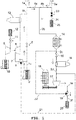
- Figure 1 shows a first preferred embodiment of the invention which allows switching from a vacuum to overpressure without having to change the position of the engine or the position of an air filter (2).
- the device comprises an inlet duct (1) arranged for being connected at a first end (1a) to an intake of a combustion engine (not shown) to be tested.
- the inlet duct (1) has a filter (2) at a second end (1c) through which air is drawn in from the outer atmosphere.
- the filter (2) allows preventing impurities from entering the device.
- the device also comprises an outlet duct (3) arranged for being connected at a first end (3a) to the exhaust of the combustion engine and which expels exhaust gases into the atmosphere through a second end (3f).
- the inlet duct (1) and the outlet duct (3) are communicated by means of a first communication duct (4), split into two sections (4a) and (4b), located close to the first ends (1a, 3a) of the inlet and outlet ducts, respectively.
- the intake of the device is thereby in communication with the exhaust thereof.
- reference numbers 1, 3 and 4 refer to the inlet duct, outlet duct and first communication duct, respectively, in their entirety.
- reference numbers When each of these reference numbers is followed by a letter (1a, 1b, 1c...; 3a, 3b, 3c...), it refers to a section of the corresponding duct. This notation is used exclusively for the sake of clarity, and the person skilled in the art will understand that they are not necessarily different ducts but rather sections of one and the same duct.
- the device also comprises a bypass valve (6) located in the inlet duct (1).
- the device further comprises a super-charging turbo assembly arranged in the inlet duct (1), which diverts the airflow in the inlet duct (1) circulating towards the bypass valve (6).
- the turbo assembly in turn comprises a turbine (8) coupled to a dissipation system for dissipating the energy generated during expansion.
- the turbine (8) is preferably a variable-geometry turbine (VGT) and more preferably a radial centripetal-type turbine.
- the dissipation system for dissipating the energy generated during expansion in the turbine consists of a radial-flow centrifugal compressor (9).
- the compressor (9) is connected to a filter (10) through which it draws in air from the atmosphere and to at least one back pressure valve (11) and a muffler (12) through which the compressor (9) discharges the drawn in air into the atmosphere.
- a first three-way valve (5) is located upstream of the turbine (8), said valve (5) being positioned for this configuration such that it allows the passage of air from the inlet duct (1c) to the turbine (8) and prevents the passage thereof to a second communication duct (21), herein described in further detail below.
- the bypass valve (6) and the turbine (8) can be controlled to obtain a desired mass flow rate and pressure value in the inlet duct (1b). Therefore, the inlet airflow in the inlet duct (1b) located downstream of the first three-way valve (5) and the bypass valve (6) is a mixture of air that expands in the turbine (8) and of air that is diverted through the bypass valve (6).
- a condensate separator (13) is arranged downstream of the turbine (8), before the drawn in air passes into the inlet duct (1b) again.
- the outlet duct (3) in the vacuum-generating operating mode shown in Figure 1 is described next.
- the control valve (23) is closed and an on/off valve (15) is open. Therefore, the exhaust gases from the outlet duct (3a), diluted with inlet air from the first communication duct (4a), are cooled (14) in a heat exchanger to a temperature safe for introduction into a turbocharger (17).
- the heat exchanger (14) can use any suitable fluid as the coolant fluid, such as tap water at room temperature.
- the turbocharger (17) is charged by turbocharger charging means, consisting of at least one electric engine (18) in this case.
- the turbocharger (17) draws in the cooled mixture of air and exhaust gases from the outlet duct (3d) in order to remove said mixture from the device.
- the electric engine (18) controls the rotational speed of the turbocharger (17) until a given desired value of the mass flow rate and pressure in the air that is taken in is reached, controlling these conditions together with the turbine (8) and the bypass valve (6).
- the mixture of air and exhaust gases drawn in by the turbocharger (17) passes through the outlet duct (3e), where a second three-way valve (19) prevents its passage towards a duct (22) and allows its passage towards the outlet duct (3f), to be discharged in the end into the atmosphere through a muffler (20).
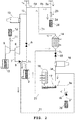
- FIG. 2 operation of a device according to the same embodiment shown in Figure 1 is described, but this time operating in an overpressure generating mode.
- the device is simulating atmospheric conditions at a level with an altitude that is less than that of the room where the test is being performed, i.e., at a higher pressure.
- the air is drawn in through the air filter (2).
- the first three-way valve (5) is closed in the direction of entry into the turbine (8) and open for diverting the flow towards a second communication duct (21), which connects the inlet duct (1c) upstream of the bypass valve (6) with the outlet duct (3d) upstream of the turbocharger (17).
- the bypass valve (6) is closed, preventing the passage of air towards the duct (1b).
- valve (15) which is located in the duct (3c) between the heat exchanger (14) and the point of connection of the outlet duct (3d) with the second communication duct (21), is closed, such that the only free path for the airflow that is drawn in is through the turbocharger (17).
- the second three-way valve (19) which connects the outlet duct (3e) downstream of the turbocharger (17) and the outlet duct (3c) between the heat exchanger (14) and the on/off valve (15), is closed in the direction towards the duct (3f), such that the airflow that is drawn in is diverted through the duct (22) and discharged into the duct (3c).
- the air drawn in from the duct (22) is discharged into the heat exchanger (14) and does not recede because the valve (15) is closed, as mentioned above.
- the only free path for the flow is towards the inlet duct (1a) coupled to the intake of the engine.
- the exhaust gases of the engine are discharged into the outlet duct (3a) and mixed with the drawn in dilution air from the duct (4b).
- the gases exit into the atmosphere through the control valve (23), arranged in a duct (24) that connects the outlet duct (3a) with the atmosphere, and that is at least partially open, and through a muffler (25).
- a section of the outlet duct (3b) connects the heat exchanger (14) with the first communication duct (4) at a point between the connection of the inlet duct (1) and the connection of the duct (24).
- the pressure drops experienced by the air as it travels through the device are due to the different mechanical obstacles it encounters (valves, pipe length, etc.).
- the reduced complexity of the device of the preferred embodiment of the present invention allows reducing these mechanical obstacles, and accordingly allows the device to simulate small pressure variations (which translate into small height variations).
- the bypass valve (6) and the direct path created between the filter (2) and the end (1a) allow improved operation of the device in vacuum mode.
- the control valve (23) and the direct path created between the end (3a) and the muffler (25) allow the improved operation of the device in overpressure mode.
- the combined action of the turbine (8) and bypass valve (6) allows cooling inlet air when the device is working in vacuum mode.
- the rotational speed of the turbocharger (17) and the position of the control valve (23) allow controlling (together with the heat exchanger (14)) the temperature of the air with respect to the atmosphere.
- conditioning and “condition” refer to performing pressure variations, temperature variations and a combination of pressure and temperature variations.
- the turbine (8) can also be coupled to an electric generator (26) which absorbs the energy obtained during expansion in the turbine (8).
- the turbocharger charging means consist of a turbine (27).
- the assembly of the turbine (27) and turbocharger (17) coupled to the same shaft can be a super-charging turbo assembly.
- the turbine (27) is operated by means of a gas flow in which the gases are generated to that end in a flow bench.
- the turbine (27) controls the rotational speed of the turbocharger (17) until a given desired mass flow rate and pressure value is achieved in the air that is taken in, controlling these conditions together with the turbine (8) and the bypass valve (6).
- the device according to the present invention has a series of advantages with respect to the prior art, such as automatic switching from a vacuum to overpressure and the possibility of simulating altitudes close to the geographic level at which the installation described in the present invention is located.
- the present invention discloses a method for conditioning the atmosphere for testing combustion engines using a device according to the first aspect of the present invention, wherein said method comprises the steps of:
- the inlet air pressure variation step in the method of the preferred embodiment of the present invention is performed by means of the combined action of a turbocharger, a turbine and a bypass valve controlling the amount of inlet air.
- the method of the present invention allows performing pressure variations simulating small height variations, for example of +/-200 m, with respect to the height at which the method is carried out, or even less, for example of +/-100 m, +/-50 m, etc.
- the inlet air pressure variation step can comprise either reducing inlet air pressure or increasing inlet air pressure.
- the method of the present invention can also comprise the step of switching between an inlet air pressure increase mode and an inlet air pressure reduction mode. Said switching of the pressure variation mode is done by simply adjusting two three-way valves, two control valves and an on/off valve.
- the method according to the preferred embodiment of the present invention further comprises the step of subjecting the atmospheric inlet air to a temperature variation step.
- this temperature variation step is performed by means of the combined use of the turbine (8) and bypass valve (6) (vacuum mode) and by means of the combined use of the turbocharger (17), control valve (23) and heat exchanger (14) (overpressure mode).
- the present invention also relates to the use of a device according to the first aspect of the present invention, as defined above in reference to Figures 1 to 4 , for conditioning pressure from the atmosphere when testing combustion engines by means of pressure variations simulating small height variations with respect to the height at which the device is located.
- a small height variation corresponds to a small pressure variation.
- the greater the airflow the device can generate the larger the size of the engines that can be tested with it.
- Height variation with respect to the device Mass flow rate (prior art) Mass flow rate (present invention) +200 m 400 kg/h 1300 kg/h +500 m 600 kg/h 1200 kg/h +1000 m 900 kg/h 1150 kg/h +2000 m 850 kg/h 1000 kg/h -200 m 200 kg/h 1900 kg/h -500 m 400 kg/h 1800 kg/h -1000 m 650 kg/h 1700 kg/h -2000 m 800 kg/h 1550 kg/h
- the device of the present invention allows obtaining much higher mass flow rates than those that could be obtained with the device of patent document ES2485618 . Since there is a higher mass flow rate, in the event of a fluctuation, the drawn in pressure does not change and the connection of the engine to the device does not affect operation of the engine itself, which allows simulating small pressure variations (which translate into in small height variations).
- the preceding table shows specific height variation values reaching up to +/-200 m
- the person skilled in the art will understand that the data in the preceding table demonstrates the tendency of the device of the present invention to provide a higher mass flow rate than the device of the prior art, regardless of the tested height variation. Therefore, the device of the present invention will also work with even smaller height variations, for example of +/-100 m, +/-50 m, etc.
- turbocharger and turbine could be coupled to other systems providing or dissipating energy, respectively, not necessarily limited to those herein described above.
Landscapes
- Physics & Mathematics (AREA)
- General Physics & Mathematics (AREA)
- Chemical & Material Sciences (AREA)
- Engineering & Computer Science (AREA)
- Combustion & Propulsion (AREA)
- Testing Of Engines (AREA)
- Supercharger (AREA)
Abstract
Description
- The present invention generally relates to the field of testing combustion engines, and more specifically to a device for conditioning the atmosphere while testing combustion engines.
- Testing and characterizing reciprocating internal combustion engines in test benches require in many circumstances precise pressure and/or temperature control, both in the intake and in the exhaust. This is the case, for example, of testing campaigns intended for calibrating engine control with altitude, cold-starting studies, repeatability of reference conditions in testing campaigns extending over time, etc.
- In many cases the problem raised is to obtain control over pressure so that it is less than atmospheric pressure, i.e., for simulating a high altitude situation. This case occurs, for example, when engine operation is to be studied at a level with a higher altitude than that of the laboratory in which testing is performed, or in the case of studying engines and aviation equipment. However, in other cases it is also desirable to reproduce low altitude conditions by increasing atmospheric pressure, for example when sea level conditions are to be reproduced in a testing room which is geographically located at a high altitude, or when engine behavior inside a mine below sea level is to be studied.
- Some methods are already known in the art for performing this type of atmospheric condition simulation.
- For example, patent document
ES2398095 A1 ES2398095 A1 - Patent document
WO2008036993 A2 discloses a method and device for supplying conditioned combustion gas to an internal combustion engine. The exhaust gases can be mixed with the air that is introduced in the intake of the engine. The internal combustion engine exhaust gases are discharged through an exhaust pipe by means of an intake system for the combustion engine exhaust gas, preferably a system including a filter, a diluting duct and a fan. - Patent document
ES2485618 ES2485618 - Therefore, although some methods and devices are known for providing a simulation of atmospheric conditions at different altitudes for testing internal combustion engines, there is still a need in the art for alternative methods and devices that provide advantages with respect to the prior art. For example, it would be desirable to have a device which allows precisely simulating small differences in altitude between the location of the installation in which testing is performed and the altitude to be simulated in the combustion engine.
- In a first aspect, the present invention discloses a device for conditioning the atmosphere for testing combustion engines which solves the aforementioned drawbacks of the prior art. To that end, the device of the present invention comprises:
- an inlet duct arranged for being connected at a first end to an intake of a combustion engine to be tested and which draws in air from the external atmosphere through a second end;
- an outlet duct arranged for being connected at a first end to the exhaust of the combustion engine and which expels exhaust gases into the atmosphere through a second end;
- a first communication duct communicating the inlet duct with the outlet duct close to its respective first ends, such that the intake of the device is in communication with the exhaust thereof;
- a bypass valve arranged in the inlet duct;
- a super-charging turbo assembly which diverts the airflow in the inlet duct circulating towards the bypass valve, the turbo assembly comprising a turbine coupled to a dissipation system for dissipating the energy generated during expansion, the bypass valve and the turbine being able to be controlled to obtain a desired pressure and airflow value in the inlet duct;
- a heat exchanger in the outlet duct for cooling the exhaust gases to a safe temperature; and
- a turbocharger in the outlet duct downstream of the heat exchanger, charged by turbocharger charging means, to control, together with the turbine and the bypass valve, the pressure of the intake air and the intake airflow.
- The device of the present invention is characterized in that it further comprises:
- a first three-way valve that connects the inlet duct upstream of the bypass valve with the outlet duct upstream of the turbocharger through a second communication duct;
- an on/off valve in the duct between the heat exchanger and the point of connection of the outlet duct with the second communication duct;
- a second three-way valve that connects the outlet duct downstream of the turbocharger and the outlet duct, between the heat exchanger and the on/off valve;
- a control valve in a duct that connects the outlet duct with the atmosphere; and
- a section of the outlet duct that connects the heat exchanger with the first communication duct between the connection of the inlet duct and the connection of the duct.
- Therefore, the configuration of the set of three-way valves, bypass valves and the on/off valve allows use of the device for increasing or reducing inlet air pressure with respect to atmospheric air, as well as easily switching from the inlet air pressure increase mode to the inlet air pressure reduction mode. Furthermore, said novel configuration of valves in the device of the present invention allows performing temperature variations simulating small height variations, for example of +/-200 m, +/-100 m, +/-50 m or even less, with respect to the height at which the device is located.
- In a second aspect, the present invention also discloses a method for conditioning the atmosphere for testing combustion engines by means of a device according to the first aspect of the present invention, wherein said method comprises the steps of:
- subjecting atmospheric inlet air to a pressure variation step;
- diverting inlet air towards the outlet in order to put exhaust gases in direct communication with the inlet air;
- introducing inlet air subjected to pressure variations at the intake of an engine to be tested;
- reducing the temperature of the exhaust gases to a safe temperature for the passage thereof through a turbocharger; and
- expelling exhaust gases from the engine being tested into the atmosphere.
- Therefore, by using the device according to the first aspect of the present invention, the method of the invention allows performing pressure variations simulating not only large but also small height variations.
- In the method of the invention, the inlet air pressure variation step is performed by means of the combined action of a turbocharger, a turbine and a bypass valve controlling the amount of inlet air.
- Finally, according to a third aspect of the present invention, the present invention also discloses the use of a device according to the first aspect of the present invention for conditioning pressure from the atmosphere when testing combustion engines by means of pressure variations simulating very small height variations, for example of +/-200 m, +/-100 m, +/-50 m or even less, with respect to the height at which the device is located.
- The present invention will be better understood in reference to the following drawings illustrating preferred embodiments of the invention which are provided by way of example and must not be interpreted as being limiting of the invention in anyway.
-
Figure 1 shows a diagram of the device according to the first embodiment of the present invention, according to a first operating mode. -
Figure 2 shows a diagram of the device according to the first embodiment of the present invention, according to a second operating mode. -
Figure 3 shows a diagram of an alternative embodiment for dissipating the energy generated during expansion in the turbine of the device of the present invention. -
Figure 4 shows a diagram of an alternative embodiment of the turbocharger of the device of the present invention. - A device according to a preferred embodiment of the present invention will be described below according to two different operating modes, referring to
Figures 1 and2 , respectively. InFigure 1 , the device is used to simulate a higher altitude with respect to the geographic level at which the combustion engine is being tested, i.e., at a lower pressure. This is the case for example of operating the engine in high mountain areas. - In
Figure 2 , the device is used to simulate a lower altitude with respect to the geographic level at which the combustion engine is being tested, i.e., at a higher pressure. This is the case of operating the engine at sea level (when the test room is installed at greater heights), for example, or even below sea level, for example, inside mines. -
Figure 1 shows a first preferred embodiment of the invention which allows switching from a vacuum to overpressure without having to change the position of the engine or the position of an air filter (2). - As seen in
Figure 1 , the device comprises an inlet duct (1) arranged for being connected at a first end (1a) to an intake of a combustion engine (not shown) to be tested. The inlet duct (1) has a filter (2) at a second end (1c) through which air is drawn in from the outer atmosphere. The filter (2) allows preventing impurities from entering the device. - The device also comprises an outlet duct (3) arranged for being connected at a first end (3a) to the exhaust of the combustion engine and which expels exhaust gases into the atmosphere through a second end (3f). The inlet duct (1) and the outlet duct (3) are communicated by means of a first communication duct (4), split into two sections (4a) and (4b), located close to the first ends (1a, 3a) of the inlet and outlet ducts, respectively. The intake of the device is thereby in communication with the exhaust thereof.
- As they are used throughout the present description, reference numbers 1, 3 and 4 refer to the inlet duct, outlet duct and first communication duct, respectively, in their entirety. When each of these reference numbers is followed by a letter (1a, 1b, 1c...; 3a, 3b, 3c...), it refers to a section of the corresponding duct. This notation is used exclusively for the sake of clarity, and the person skilled in the art will understand that they are not necessarily different ducts but rather sections of one and the same duct.
- So in
Figure 1 , which represents a case where the device is generating a vacuum, inlet air circulates through the first communication duct (4a) from the inlet duct (1) to the outlet duct (3), said air being the difference between the air drawn in by the equipment through the filter (2) and the air required by the engine. Therefore, there is a mixture of air and exhaust gas in the outlet duct (3b). To that end, a control valve (23) (herein described in further detail below) is completely closed. - The device also comprises a bypass valve (6) located in the inlet duct (1).
- The device further comprises a super-charging turbo assembly arranged in the inlet duct (1), which diverts the airflow in the inlet duct (1) circulating towards the bypass valve (6). The turbo assembly in turn comprises a turbine (8) coupled to a dissipation system for dissipating the energy generated during expansion. The turbine (8) is preferably a variable-geometry turbine (VGT) and more preferably a radial centripetal-type turbine.
- According to the preferred embodiment of the present invention shown in
Figures 1 and2 , the dissipation system for dissipating the energy generated during expansion in the turbine consists of a radial-flow centrifugal compressor (9). The compressor (9) is connected to a filter (10) through which it draws in air from the atmosphere and to at least one back pressure valve (11) and a muffler (12) through which the compressor (9) discharges the drawn in air into the atmosphere. - Furthermore, a first three-way valve (5) is located upstream of the turbine (8), said valve (5) being positioned for this configuration such that it allows the passage of air from the inlet duct (1c) to the turbine (8) and prevents the passage thereof to a second communication duct (21), herein described in further detail below.
- The bypass valve (6) and the turbine (8) can be controlled to obtain a desired mass flow rate and pressure value in the inlet duct (1b). Therefore, the inlet airflow in the inlet duct (1b) located downstream of the first three-way valve (5) and the bypass valve (6) is a mixture of air that expands in the turbine (8) and of air that is diverted through the bypass valve (6).
- Finally, a condensate separator (13) is arranged downstream of the turbine (8), before the drawn in air passes into the inlet duct (1b) again.
- The outlet duct (3) in the vacuum-generating operating mode shown in
Figure 1 is described next. In this case, the control valve (23) is closed and an on/off valve (15) is open. Therefore, the exhaust gases from the outlet duct (3a), diluted with inlet air from the first communication duct (4a), are cooled (14) in a heat exchanger to a temperature safe for introduction into a turbocharger (17). - The heat exchanger (14) can use any suitable fluid as the coolant fluid, such as tap water at room temperature.
- After the heat exchanger (14) and before the turbocharger (17), the exhaust gases are passed through a condensate separator (16).
- The turbocharger (17) is charged by turbocharger charging means, consisting of at least one electric engine (18) in this case. The turbocharger (17) draws in the cooled mixture of air and exhaust gases from the outlet duct (3d) in order to remove said mixture from the device. The electric engine (18) controls the rotational speed of the turbocharger (17) until a given desired value of the mass flow rate and pressure in the air that is taken in is reached, controlling these conditions together with the turbine (8) and the bypass valve (6).
- The mixture of air and exhaust gases drawn in by the turbocharger (17) passes through the outlet duct (3e), where a second three-way valve (19) prevents its passage towards a duct (22) and allows its passage towards the outlet duct (3f), to be discharged in the end into the atmosphere through a muffler (20).
- Now referring to
Figure 2 , operation of a device according to the same embodiment shown inFigure 1 is described, but this time operating in an overpressure generating mode. In other words, in the operating mode ofFigure 2 the device is simulating atmospheric conditions at a level with an altitude that is less than that of the room where the test is being performed, i.e., at a higher pressure. - The elements in
Figure 2 are the same as those shown inFigure 1 and have the same reference numbers, so they will not be described in further detail. The only difference betweenFigures 1 and2 is the position of the opening of the valves and therefore the path followed by the air as it passes through the installation. - Therefore in the embodiment of
Figure 2 , to work at a pressure that is higher than atmospheric pressure, i.e., in the case of an overpressure-generating operation of the device, the air is drawn in through the air filter (2). In this case, the first three-way valve (5) is closed in the direction of entry into the turbine (8) and open for diverting the flow towards a second communication duct (21), which connects the inlet duct (1c) upstream of the bypass valve (6) with the outlet duct (3d) upstream of the turbocharger (17). The bypass valve (6) is closed, preventing the passage of air towards the duct (1b). - Furthermore, the valve (15), which is located in the duct (3c) between the heat exchanger (14) and the point of connection of the outlet duct (3d) with the second communication duct (21), is closed, such that the only free path for the airflow that is drawn in is through the turbocharger (17). The second three-way valve (19), which connects the outlet duct (3e) downstream of the turbocharger (17) and the outlet duct (3c) between the heat exchanger (14) and the on/off valve (15), is closed in the direction towards the duct (3f), such that the airflow that is drawn in is diverted through the duct (22) and discharged into the duct (3c).
- Therefore, the air drawn in from the duct (22) is discharged into the heat exchanger (14) and does not recede because the valve (15) is closed, as mentioned above. The only free path for the flow is towards the inlet duct (1a) coupled to the intake of the engine.
- In addition, the exhaust gases of the engine are discharged into the outlet duct (3a) and mixed with the drawn in dilution air from the duct (4b). Finally, the gases exit into the atmosphere through the control valve (23), arranged in a duct (24) that connects the outlet duct (3a) with the atmosphere, and that is at least partially open, and through a muffler (25).
- It can be seen that a section of the outlet duct (3b) connects the heat exchanger (14) with the first communication duct (4) at a point between the connection of the inlet duct (1) and the connection of the duct (24).
- Therefore, it can be seen that configuration of the set of three-way valves (5, 19), bypass valves (6, 23) and on/off valve (15) allows use of the device for increasing or reducing inlet air pressure with respect to atmospheric air. Switching from one operating mode to another is done in a quick and simple manner by simply acting on this series of valves. Furthermore, the specific arrangement of ducts and valves, herein described in detail above and shown in the attached drawings, provides significant improvements with respect to similar devices known in the prior art. For example, the specific design of the device disclosed in the present invention is simpler than similar devices in the prior art, so it is easier and less expensive to manufacture as well as to automate and be operated by operators.
- In addition, in a manner that is very advantageous with respect to the prior art, reducing the design complexity of the device of the present invention with respect to the prior art makes it possible to precisely simulate very small height variations, for example of +/-200 m, +/-100 m, +/-50 m or less, with respect to the height at which the device is located, which was not possible with similar devices in the prior art, for example the device disclosed in patent document
ES 2485618 - In fact, the pressure drops experienced by the air as it travels through the device are due to the different mechanical obstacles it encounters (valves, pipe length, etc.). The reduced complexity of the device of the preferred embodiment of the present invention allows reducing these mechanical obstacles, and accordingly allows the device to simulate small pressure variations (which translate into small height variations). Specifically, the bypass valve (6) and the direct path created between the filter (2) and the end (1a) allow improved operation of the device in vacuum mode. In turn, the control valve (23) and the direct path created between the end (3a) and the muffler (25) allow the improved operation of the device in overpressure mode.
- In addition, the person skilled in the art will understand that the combined action of the turbine (8) and bypass valve (6) allows cooling inlet air when the device is working in vacuum mode. In addition, when the device is working in overpressure mode, the rotational speed of the turbocharger (17) and the position of the control valve (23) allow controlling (together with the heat exchanger (14)) the temperature of the air with respect to the atmosphere.
- Therefore, as they are used herein the terms "conditioning" and "condition" refer to performing pressure variations, temperature variations and a combination of pressure and temperature variations.
- Now referring to the embodiment shown in
Figure 3 , it can be seen that the turbine (8) can also be coupled to an electric generator (26) which absorbs the energy obtained during expansion in the turbine (8). - According to another preferred embodiment shown in
Figure 4 , the turbocharger charging means consist of a turbine (27). The assembly of the turbine (27) and turbocharger (17) coupled to the same shaft can be a super-charging turbo assembly. The turbine (27) is operated by means of a gas flow in which the gases are generated to that end in a flow bench. In this embodiment of the present invention, the turbine (27) controls the rotational speed of the turbocharger (17) until a given desired mass flow rate and pressure value is achieved in the air that is taken in, controlling these conditions together with the turbine (8) and the bypass valve (6). - As can be inferred from the preceding description, and as mentioned above herein, the device according to the present invention has a series of advantages with respect to the prior art, such as automatic switching from a vacuum to overpressure and the possibility of simulating altitudes close to the geographic level at which the installation described in the present invention is located.
- The present invention discloses a method for conditioning the atmosphere for testing combustion engines using a device according to the first aspect of the present invention, wherein said method comprises the steps of:
- subjecting atmospheric inlet air to a pressure variation step;
- diverting inlet air towards the outlet in order to put exhaust gases in direct communication with the inlet air;
- introducing inlet air subjected to pressure variations at the intake of an engine to be tested;
- reducing the temperature of the exhaust gases to a safe temperature for the passage thereof through a turbocharger; and
- expelling exhaust gases from the engine being tested into the atmosphere.
- The inlet air pressure variation step in the method of the preferred embodiment of the present invention is performed by means of the combined action of a turbocharger, a turbine and a bypass valve controlling the amount of inlet air.
- Therefore, the method of the present invention allows performing pressure variations simulating small height variations, for example of +/-200 m, with respect to the height at which the method is carried out, or even less, for example of +/-100 m, +/-50 m, etc.
- According to the present invention, the inlet air pressure variation step can comprise either reducing inlet air pressure or increasing inlet air pressure.
- Furthermore, the method of the present invention can also comprise the step of switching between an inlet air pressure increase mode and an inlet air pressure reduction mode. Said switching of the pressure variation mode is done by simply adjusting two three-way valves, two control valves and an on/off valve.
- In addition, the method according to the preferred embodiment of the present invention further comprises the step of subjecting the atmospheric inlet air to a temperature variation step. By using the device of the present invention as described above herein, this temperature variation step is performed by means of the combined use of the turbine (8) and bypass valve (6) (vacuum mode) and by means of the combined use of the turbocharger (17), control valve (23) and heat exchanger (14) (overpressure mode).
- Finally, the present invention also relates to the use of a device according to the first aspect of the present invention, as defined above in reference to
Figures 1 to 4 , for conditioning pressure from the atmosphere when testing combustion engines by means of pressure variations simulating small height variations with respect to the height at which the device is located. - Comparative data relating to the operation of a device according to the preferred embodiment of the present invention with respect to the operation of a device of the prior art (device from patent document
ES2485618 - The following table shows the maximum airflow rates that can be reached for different height variations by means of the device of patent document
ES2485618 - As explained above, a small height variation corresponds to a small pressure variation. In turn, the greater the airflow the device can generate, the larger the size of the engines that can be tested with it.
Height variation with respect to the device Mass flow rate (prior art) Mass flow rate (present invention) +200 m 400 kg/h 1300 kg/h +500 m 600 kg/h 1200 kg/h +1000 m 900 kg/h 1150 kg/h +2000 m 850 kg/h 1000 kg/h -200 m 200 kg/h 1900 kg/h -500 m 400 kg/h 1800 kg/h -1000 m 650 kg/h 1700 kg/h -2000 m 800 kg/h 1550 kg/h - As can be seen in the preceding table, for all height variations the device of the present invention allows obtaining much higher mass flow rates than those that could be obtained with the device of patent document
ES2485618 - For example, a 1.6 L engine moves about 275 kg/h. Therefore, engines larger than this could not really be tested with the device of the prior art. This involves a very limited range of use of the device of the prior art for small heights.
- In addition, it can be seen that with the device of the prior art the flow rate increases as the height variation increases to +1000 m, which means that the device is not very operative between zero and that height (1000 m) in the vacuum mode. The same occurs in the case of overpressure to -5000 m (data not shown). With the device of the present invention, it can be seen that the mass flow rate obtained always decreases as the height variation increases, whether this is a positive or negative variation, which is more consistent with what actually happens with engines, and therefore the device of the present invention is more operative.
- Although the preceding table shows specific height variation values reaching up to +/-200 m, the person skilled in the art will understand that the data in the preceding table demonstrates the tendency of the device of the present invention to provide a higher mass flow rate than the device of the prior art, regardless of the tested height variation. Therefore, the device of the present invention will also work with even smaller height variations, for example of +/-100 m, +/-50 m, etc.
- Although the present invention has been described in reference to preferred embodiments thereof, the person skilled in the art will understand that modifications and variations can be applied to the described embodiments without departing from the scope of the present invention as a result. For example, the turbocharger and turbine could be coupled to other systems providing or dissipating energy, respectively, not necessarily limited to those herein described above.
- Likewise, although preferred embodiments of the device of the present invention comprising a single turbine (8), a single bypass valve (6), a single heat exchanger (14) and a single turbocharger (17) have been described, it will be evident for a person skilled in the art that alternative embodiments of the device of the present invention can include several of these elements.
- The person skilled in the art will also understand that although the present invention has been described by referring to internal combustion engine testing, said invention can also be applied with minor modifications to the testing of other associated elements which may also have to work at different altitudes (such as for example, air filters, mufflers, and exhaust gas cleaning elements (post-treatment), etc.)
Claims (17)
- A device for conditioning the atmosphere when testing reciprocating internal combustion engines, wherein the device comprises:- an inlet duct (1) arranged for being connected at a first end (1a) to an intake of a combustion engine to be tested and which draws in air from the external atmosphere through a second end (1c);- an outlet duct (3) arranged for being connected at a first end (3a) to the exhaust of the combustion engine and which expels exhaust gases into the atmosphere through a second end (3f);- a first communication duct (4) communicating the inlet duct (1) with the outlet duct (3) close to its respective first ends (1a, 3a), such that the intake of the device is in communication with the exhaust thereof;- a bypass valve (6) arranged in the inlet duct (1);- a super-charging turbo assembly which diverts the airflow in the inlet duct (1) circulating towards the bypass valve (6), the turbo assembly comprising a turbine (8) coupled to a dissipation system for dissipating the energy generated during expansion, the bypass valve (6) and the turbine (8) being able to be controlled to obtain the desired pressure and airflow value in the inlet duct (1);- a heat exchanger (14) in the outlet duct for cooling the exhaust gases to a safe temperature; and- a turbocharger (17) in the outlet duct (3) downstream of the heat exchanger (14), charged by turbocharger charging means, to control, together with the turbine (8) and the bypass valve (6), the pressure of the intake air and the intake airflow;characterized in that it further comprises- a first three-way valve (5) that connects the inlet duct (1c) upstream of the bypass valve (6) with the outlet duct (3d) upstream of the turbocharger (17) through a second communication duct (21);- an on/off valve (15) in the duct (3c) between the heat exchanger (14) and the point of connection of the outlet duct (3d) with the second communication duct (21);- a second three-way valve (19) that connects the outlet duct (3e) downstream of the turbocharger (17) and the outlet duct (3c), between the heat exchanger (14) and the on/off valve (15);- a control valve (23) in a duct (24) that connects the outlet duct (3a) with the atmosphere; and- a section of the outlet duct (3b) that connects the heat exchanger (14) with the first communication duct (4) between the connection of the inlet duct (1) and the connection of the duct (24);such that the configuration of the set of three-way valves (5, 19), bypass valves (6, 23) and the on/off valve (15) allows use of the device for increasing or reducing inlet air pressure with respect to atmospheric air.
- The device according to the preceding claim, characterized in that it further comprises a muffler (20) at the second end of the outlet duct (3f).
- The device according to any of the preceding claims, characterized in that it further comprises a muffler (25) at an outlet end of the duct (24).
- The device according to any of the preceding claims, characterized in that the dissipation system for dissipating the energy generated during expansion in the turbine (8) consists of a radial-flow centrifugal compressor (9) which is connected to a filter (10) through which it draws in air from the atmosphere and to a back pressure valve (11) and a muffler (12) through which it discharges the air which is given off into the atmosphere.
- The device according to any of claims 1 to 3, characterized in that the dissipation system for dissipating the energy generated during expansion in the turbine (8) consists of an electric generator (26).
- The device according to any of the preceding claims, characterized in that the turbine (8) is a variable-geometry turbine.
- The device according to claim 6, characterized in that the variable-geometry turbine is a radial centripetal-type turbine.
- The device according to any of the preceding claims, characterized in that the turbocharger charging means are selected from an electric engine (18) and a turbine (27).
- The device according to any of the preceding claims, characterized in that it further comprises a filter (2) at the end of the device through which air is drawn in from the outer atmosphere to prevent impurities from entering the device.
- The device according to any of the preceding claims, characterized in that it further comprises at least one condensate separator (13, 16).
- A method for conditioning the atmosphere for testing combustion engines by means of a device for conditioning the atmosphere according to any of claims 1 to 10, wherein the method comprises the steps of:- subjecting atmospheric inlet air to a pressure variation step;- diverting inlet air towards the outlet in order to put exhaust gases in direct communication with the inlet air;- introducing inlet air subjected to pressure variations at the intake of an engine to be tested;- reducing the temperature of the exhaust gases to a safe temperature for the passage thereof through a turbocharger; and- expelling exhaust gases from the engine being tested into the atmosphere;wherein the method allows performing pressure variations simulating small height variations with respect to the height at which the method is carried out,
wherein the inlet air pressure variation step is performed by means of the combined action of a turbocharger, a turbine and a bypass valve controlling the amount of inlet air. - The method according to claim 11, characterized in that the obtained pressure variations simulate height variations of +/-200 m with respect to the height at which the method is carried out.
- The method according to any of claims 11 and 12, characterized in that the inlet air pressure variation step comprises reducing inlet air pressure.
- The method according to any of claims 11 and 12, characterized in that the inlet air pressure variation step comprises increasing inlet air pressure.
- The method according to any of claims 11 and 12, characterized in that it comprises the step of:- switching between an inlet air pressure increase mode and an inlet air pressure reduction mode,wherein said switching of the pressure variation mode is done by simply adjusting two three-way valves, two control valves and an on/off valve.
- The method according to any of claims 11 to 15, characterized in that it further comprises the step of subjecting the atmospheric inlet air to a temperature variation step.
- Use of a device as defined in any of claims 1 to 10 for conditioning pressure from the atmosphere when testing combustion engines by means of pressure variations simulating small height variations with respect to the height at which the method is carried out.
Applications Claiming Priority (2)
| Application Number | Priority Date | Filing Date | Title |
|---|---|---|---|
| ES201530075A ES2544516B1 (en) | 2015-01-21 | 2015-01-21 | Device for conditioning the atmosphere in tests of alternative internal combustion engines, procedure and use of said device |
| PCT/ES2016/070008 WO2016116642A1 (en) | 2015-01-21 | 2016-01-12 | Device for conditioning the atmosphere in tests of alternative internal combustion engines, method and use of said device |
Publications (3)
| Publication Number | Publication Date |
|---|---|
| EP3249376A1 true EP3249376A1 (en) | 2017-11-29 |
| EP3249376A4 EP3249376A4 (en) | 2018-08-15 |
| EP3249376B1 EP3249376B1 (en) | 2020-02-26 |
Family
ID=53939550
Family Applications (1)
| Application Number | Title | Priority Date | Filing Date |
|---|---|---|---|
| EP16739819.7A Active EP3249376B1 (en) | 2015-01-21 | 2016-01-12 | Device for conditioning the atmosphere in tests of internal combustion engines, method and use of said device |
Country Status (7)
| Country | Link |
|---|---|
| US (1) | US10684195B2 (en) |
| EP (1) | EP3249376B1 (en) |
| JP (1) | JP6662884B2 (en) |
| KR (1) | KR102045131B1 (en) |
| CN (1) | CN107407618B (en) |
| ES (2) | ES2544516B1 (en) |
| WO (1) | WO2016116642A1 (en) |
Cited By (1)
| Publication number | Priority date | Publication date | Assignee | Title |
|---|---|---|---|---|
| CN110274766A (en) * | 2019-07-11 | 2019-09-24 | 北京易盛泰和科技有限公司 | A kind of internal combustion engine altitude environment simulation system and analogy method |
Families Citing this family (10)
| Publication number | Priority date | Publication date | Assignee | Title |
|---|---|---|---|---|
| KR101953905B1 (en) * | 2016-12-29 | 2019-03-04 | 주식회사 현대케피코 | Methood for response assessment of map sensor |
| WO2019114935A1 (en) | 2017-12-12 | 2019-06-20 | Horiba Europe Gmbh | Device, method and use for conditioning intake air for testing internal combustion engines |
| CN112485008B (en) * | 2020-11-11 | 2022-07-29 | 中汽研汽车检验中心(天津)有限公司 | Aftertreatment temperature control device and method for diesel engine in-loop |
| ES2875173B2 (en) * | 2021-03-11 | 2023-06-15 | Univ Valencia Politecnica | DEVICE AND PROCEDURE FOR EMULATION OF SUPERCHARGING SYSTEMS |
| KR102610207B1 (en) * | 2021-06-30 | 2023-12-06 | 한국항공우주연구원 | Device for Simulating High-altitude Pressure Conditions using Turbo-Charger System |
| CN115266173A (en) * | 2022-08-05 | 2022-11-01 | 康湃能动流体科技(江苏)有限公司 | Turboexpander test environment simulation system and working method |
| CN116007910B (en) * | 2022-09-29 | 2025-11-21 | 国家能源集团宁夏煤业有限责任公司 | Filtering detection device |
| CN116539313B (en) * | 2023-03-27 | 2025-09-02 | 华南理工大学 | A performance test bench and test method for an electric turbocompound air compressor |
| CN116754237B (en) * | 2023-06-19 | 2026-04-24 | 一汽解放汽车有限公司 | Simulation test system for fuel cell engine turbochargers |
| CN118518366B (en) * | 2024-07-19 | 2024-10-01 | 潍坊富源增压器有限公司 | Large-scale turbocharger test bench |
Family Cites Families (12)
| Publication number | Priority date | Publication date | Assignee | Title |
|---|---|---|---|---|
| US3996793A (en) * | 1976-04-05 | 1976-12-14 | Robert Topper | Pressure control test apparatus |
| US7181379B2 (en) * | 2003-03-17 | 2007-02-20 | Environmental Testing Corporation | Variable altitude simulator system for testing engines and vehicles |
| JP4136809B2 (en) * | 2003-06-25 | 2008-08-20 | 株式会社島津製作所 | Air conditioner for aircraft |
| CN101096926B (en) * | 2006-06-30 | 2011-02-02 | 卡特彼勒公司 | Altitude compensation of turbo-charger exhaust valve |
| AT8868U3 (en) * | 2006-09-28 | 2007-10-15 | Avl List Gmbh | METHOD AND DEVICE FOR SUPPLYING A COMBUSTION ENGINE COMBUSTION ENGINE COMBUSTION ENGINE |
| CN201600243U (en) * | 2009-12-21 | 2010-10-06 | 中国人民解放军军事交通学院 | An experimental device for measuring engine performance in a simulated plateau environment |
| KR20120011565A (en) * | 2010-07-29 | 2012-02-08 | 현대자동차주식회사 | Intake and exhaust system of the engine |
| ES2398095B1 (en) * | 2011-01-31 | 2014-01-27 | Universidad Politécnica De Valencia | INSTALLATION TO SIMULATE THE AIR PRESSURE AND TEMPERATURE CONDITIONS ASPIRED BY AN ALTERNATIVE INTERNAL COMBUSTION ENGINE. |
| CN102818706B (en) * | 2012-08-28 | 2015-05-20 | 上海交通大学 | Simulating test method for plateau performance of supercharged engine and device for implementing simulating test method |
| ES2485618B1 (en) * | 2014-01-24 | 2015-04-01 | Universitat Politècnica De València | Atmospheric conditioning device for combustion engine testing, related procedure and use |
| US9650973B1 (en) * | 2015-10-30 | 2017-05-16 | Ford Global Technologies, Llc | Methods and systems for airflow control |
| WO2019114935A1 (en) * | 2017-12-12 | 2019-06-20 | Horiba Europe Gmbh | Device, method and use for conditioning intake air for testing internal combustion engines |
-
2015
- 2015-01-21 ES ES201530075A patent/ES2544516B1/en active Active
-
2016
- 2016-01-12 JP JP2017536334A patent/JP6662884B2/en active Active
- 2016-01-12 CN CN201680006605.9A patent/CN107407618B/en active Active
- 2016-01-12 ES ES16739819T patent/ES2791297T3/en active Active
- 2016-01-12 KR KR1020177023062A patent/KR102045131B1/en active Active
- 2016-01-12 EP EP16739819.7A patent/EP3249376B1/en active Active
- 2016-01-12 US US15/545,132 patent/US10684195B2/en active Active
- 2016-01-12 WO PCT/ES2016/070008 patent/WO2016116642A1/en not_active Ceased
Cited By (1)
| Publication number | Priority date | Publication date | Assignee | Title |
|---|---|---|---|---|
| CN110274766A (en) * | 2019-07-11 | 2019-09-24 | 北京易盛泰和科技有限公司 | A kind of internal combustion engine altitude environment simulation system and analogy method |
Also Published As
| Publication number | Publication date |
|---|---|
| EP3249376B1 (en) | 2020-02-26 |
| JP6662884B2 (en) | 2020-03-11 |
| ES2791297T3 (en) | 2020-11-03 |
| KR102045131B1 (en) | 2019-11-14 |
| ES2544516B1 (en) | 2016-05-12 |
| US20180283990A1 (en) | 2018-10-04 |
| WO2016116642A1 (en) | 2016-07-28 |
| ES2544516A1 (en) | 2015-08-31 |
| JP2018504596A (en) | 2018-02-15 |
| EP3249376A4 (en) | 2018-08-15 |
| KR20170125022A (en) | 2017-11-13 |
| CN107407618A (en) | 2017-11-28 |
| US10684195B2 (en) | 2020-06-16 |
| CN107407618B (en) | 2019-11-29 |
Similar Documents
| Publication | Publication Date | Title |
|---|---|---|
| EP3249376B1 (en) | Device for conditioning the atmosphere in tests of internal combustion engines, method and use of said device | |
| EP3098586B1 (en) | Device for atmosphere conditioning for testing combustion engines, and associated method and use | |
| US9260974B2 (en) | System and method for active clearance control | |
| EP3705685B1 (en) | System and method of reducing post-shutdown engine temperatures | |
| US9399951B2 (en) | Modular louver system | |
| CN107120146B (en) | Active HPC Gap Control | |
| EP3228836A1 (en) | Conditioned low pressure compressor compartment for gas turbine engine | |
| JP5788025B2 (en) | A device for simulating the pressure and temperature conditions of air taken in by a reciprocating internal combustion engine | |
| JP2017106442A (en) | Gas turbine engine fluid cooling systems and methods of assembling the same | |
| EP3184781A1 (en) | High pressure bleed air muffling device with multiple sources | |
| CN107690407A (en) | Without primary heat exchanger and exhaust (cabin bleed) assistance | |
| JP5932121B1 (en) | Gas turbine plant and method for improving existing gas turbine plant | |
| US10036321B2 (en) | Systems and methods for utilizing gas turbine compartment ventilation discharge air |
Legal Events
| Date | Code | Title | Description |
|---|---|---|---|
| STAA | Information on the status of an ep patent application or granted ep patent |
Free format text: STATUS: THE INTERNATIONAL PUBLICATION HAS BEEN MADE |
|
| PUAI | Public reference made under article 153(3) epc to a published international application that has entered the european phase |
Free format text: ORIGINAL CODE: 0009012 |
|
| STAA | Information on the status of an ep patent application or granted ep patent |
Free format text: STATUS: REQUEST FOR EXAMINATION WAS MADE |
|
| 17P | Request for examination filed |
Effective date: 20170802 |
|
| AK | Designated contracting states |
Kind code of ref document: A1 Designated state(s): AL AT BE BG CH CY CZ DE DK EE ES FI FR GB GR HR HU IE IS IT LI LT LU LV MC MK MT NL NO PL PT RO RS SE SI SK SM TR |
|
| AX | Request for extension of the european patent |
Extension state: BA ME |
|
| DAV | Request for validation of the european patent (deleted) | ||
| DAX | Request for extension of the european patent (deleted) | ||
| A4 | Supplementary search report drawn up and despatched |
Effective date: 20180717 |
|
| RIC1 | Information provided on ipc code assigned before grant |
Ipc: G01M 15/02 20060101ALI20180711BHEP Ipc: G01M 15/10 20060101ALI20180711BHEP Ipc: G01M 15/04 20060101AFI20180711BHEP |
|
| RIC1 | Information provided on ipc code assigned before grant |
Ipc: G01M 15/02 20060101ALI20190709BHEP Ipc: G01M 15/10 20060101ALI20190709BHEP Ipc: G01M 15/09 20060101ALI20190709BHEP Ipc: G01M 15/04 20060101AFI20190709BHEP |
|
| GRAP | Despatch of communication of intention to grant a patent |
Free format text: ORIGINAL CODE: EPIDOSNIGR1 |
|
| STAA | Information on the status of an ep patent application or granted ep patent |
Free format text: STATUS: GRANT OF PATENT IS INTENDED |
|
| RIN1 | Information on inventor provided before grant (corrected) |
Inventor name: DESANTES FERNANDEZ, JOSE MARIA Inventor name: PAYRI GONZALEZ, FRANCISCO Inventor name: GALINDO LUCAS, JOSE Inventor name: PIQUERAS CABRERA, PEDRO Inventor name: SERRANO CRUZ, JOSE RAMON |
|
| INTG | Intention to grant announced |
Effective date: 20190919 |
|
| RAP1 | Party data changed (applicant data changed or rights of an application transferred) |
Owner name: UNIVERSITAT POLITECNICA DE VALENCIA |
|
| GRAS | Grant fee paid |
Free format text: ORIGINAL CODE: EPIDOSNIGR3 |
|
| GRAA | (expected) grant |
Free format text: ORIGINAL CODE: 0009210 |
|
| STAA | Information on the status of an ep patent application or granted ep patent |
Free format text: STATUS: THE PATENT HAS BEEN GRANTED |
|
| GRAT | Correction requested after decision to grant or after decision to maintain patent in amended form |
Free format text: ORIGINAL CODE: EPIDOSNCDEC |
|
| AK | Designated contracting states |
Kind code of ref document: B1 Designated state(s): AL AT BE BG CH CY CZ DE DK EE ES FI FR GB GR HR HU IE IS IT LI LT LU LV MC MK MT NL NO PL PT RO RS SE SI SK SM TR |
|
| REG | Reference to a national code |
Ref country code: GB Ref legal event code: FG4D |
|
| REG | Reference to a national code |
Ref country code: CH Ref legal event code: EP |
|
| REG | Reference to a national code |
Ref country code: AT Ref legal event code: REF Ref document number: 1238236 Country of ref document: AT Kind code of ref document: T Effective date: 20200315 |
|
| REG | Reference to a national code |
Ref country code: IE Ref legal event code: FG4D |
|
| REG | Reference to a national code |
Ref country code: DE Ref legal event code: R096 Ref document number: 602016030588 Country of ref document: DE |
|
| RAP2 | Party data changed (patent owner data changed or rights of a patent transferred) |
Owner name: UNIVERSITAT POLITECNICA DE VALENCIA |
|
| PG25 | Lapsed in a contracting state [announced via postgrant information from national office to epo] |
Ref country code: NO Free format text: LAPSE BECAUSE OF FAILURE TO SUBMIT A TRANSLATION OF THE DESCRIPTION OR TO PAY THE FEE WITHIN THE PRESCRIBED TIME-LIMIT Effective date: 20200526 Ref country code: FI Free format text: LAPSE BECAUSE OF FAILURE TO SUBMIT A TRANSLATION OF THE DESCRIPTION OR TO PAY THE FEE WITHIN THE PRESCRIBED TIME-LIMIT Effective date: 20200226 Ref country code: RS Free format text: LAPSE BECAUSE OF FAILURE TO SUBMIT A TRANSLATION OF THE DESCRIPTION OR TO PAY THE FEE WITHIN THE PRESCRIBED TIME-LIMIT Effective date: 20200226 |
|
| REG | Reference to a national code |
Ref country code: NL Ref legal event code: MP Effective date: 20200226 |
|
| REG | Reference to a national code |
Ref country code: LT Ref legal event code: MG4D |
|
| PG25 | Lapsed in a contracting state [announced via postgrant information from national office to epo] |
Ref country code: LV Free format text: LAPSE BECAUSE OF FAILURE TO SUBMIT A TRANSLATION OF THE DESCRIPTION OR TO PAY THE FEE WITHIN THE PRESCRIBED TIME-LIMIT Effective date: 20200226 Ref country code: IS Free format text: LAPSE BECAUSE OF FAILURE TO SUBMIT A TRANSLATION OF THE DESCRIPTION OR TO PAY THE FEE WITHIN THE PRESCRIBED TIME-LIMIT Effective date: 20200626 Ref country code: SE Free format text: LAPSE BECAUSE OF FAILURE TO SUBMIT A TRANSLATION OF THE DESCRIPTION OR TO PAY THE FEE WITHIN THE PRESCRIBED TIME-LIMIT Effective date: 20200226 Ref country code: HR Free format text: LAPSE BECAUSE OF FAILURE TO SUBMIT A TRANSLATION OF THE DESCRIPTION OR TO PAY THE FEE WITHIN THE PRESCRIBED TIME-LIMIT Effective date: 20200226 Ref country code: BG Free format text: LAPSE BECAUSE OF FAILURE TO SUBMIT A TRANSLATION OF THE DESCRIPTION OR TO PAY THE FEE WITHIN THE PRESCRIBED TIME-LIMIT Effective date: 20200526 |
|
| PG25 | Lapsed in a contracting state [announced via postgrant information from national office to epo] |
Ref country code: NL Free format text: LAPSE BECAUSE OF FAILURE TO SUBMIT A TRANSLATION OF THE DESCRIPTION OR TO PAY THE FEE WITHIN THE PRESCRIBED TIME-LIMIT Effective date: 20200226 |
|
| PG25 | Lapsed in a contracting state [announced via postgrant information from national office to epo] |
Ref country code: PT Free format text: LAPSE BECAUSE OF FAILURE TO SUBMIT A TRANSLATION OF THE DESCRIPTION OR TO PAY THE FEE WITHIN THE PRESCRIBED TIME-LIMIT Effective date: 20200719 Ref country code: SM Free format text: LAPSE BECAUSE OF FAILURE TO SUBMIT A TRANSLATION OF THE DESCRIPTION OR TO PAY THE FEE WITHIN THE PRESCRIBED TIME-LIMIT Effective date: 20200226 Ref country code: EE Free format text: LAPSE BECAUSE OF FAILURE TO SUBMIT A TRANSLATION OF THE DESCRIPTION OR TO PAY THE FEE WITHIN THE PRESCRIBED TIME-LIMIT Effective date: 20200226 Ref country code: DK Free format text: LAPSE BECAUSE OF FAILURE TO SUBMIT A TRANSLATION OF THE DESCRIPTION OR TO PAY THE FEE WITHIN THE PRESCRIBED TIME-LIMIT Effective date: 20200226 Ref country code: CZ Free format text: LAPSE BECAUSE OF FAILURE TO SUBMIT A TRANSLATION OF THE DESCRIPTION OR TO PAY THE FEE WITHIN THE PRESCRIBED TIME-LIMIT Effective date: 20200226 Ref country code: RO Free format text: LAPSE BECAUSE OF FAILURE TO SUBMIT A TRANSLATION OF THE DESCRIPTION OR TO PAY THE FEE WITHIN THE PRESCRIBED TIME-LIMIT Effective date: 20200226 Ref country code: LT Free format text: LAPSE BECAUSE OF FAILURE TO SUBMIT A TRANSLATION OF THE DESCRIPTION OR TO PAY THE FEE WITHIN THE PRESCRIBED TIME-LIMIT Effective date: 20200226 Ref country code: SK Free format text: LAPSE BECAUSE OF FAILURE TO SUBMIT A TRANSLATION OF THE DESCRIPTION OR TO PAY THE FEE WITHIN THE PRESCRIBED TIME-LIMIT Effective date: 20200226 |
|
| REG | Reference to a national code |
Ref country code: ES Ref legal event code: FG2A Ref document number: 2791297 Country of ref document: ES Kind code of ref document: T3 Effective date: 20201103 |
|
| REG | Reference to a national code |
Ref country code: AT Ref legal event code: MK05 Ref document number: 1238236 Country of ref document: AT Kind code of ref document: T Effective date: 20200226 |
|
| REG | Reference to a national code |
Ref country code: DE Ref legal event code: R097 Ref document number: 602016030588 Country of ref document: DE |
|
| PLBE | No opposition filed within time limit |
Free format text: ORIGINAL CODE: 0009261 |
|
| STAA | Information on the status of an ep patent application or granted ep patent |
Free format text: STATUS: NO OPPOSITION FILED WITHIN TIME LIMIT |
|
| PG25 | Lapsed in a contracting state [announced via postgrant information from national office to epo] |
Ref country code: IT Free format text: LAPSE BECAUSE OF FAILURE TO SUBMIT A TRANSLATION OF THE DESCRIPTION OR TO PAY THE FEE WITHIN THE PRESCRIBED TIME-LIMIT Effective date: 20200226 Ref country code: AT Free format text: LAPSE BECAUSE OF FAILURE TO SUBMIT A TRANSLATION OF THE DESCRIPTION OR TO PAY THE FEE WITHIN THE PRESCRIBED TIME-LIMIT Effective date: 20200226 |
|
| 26N | No opposition filed |
Effective date: 20201127 |
|
| PG25 | Lapsed in a contracting state [announced via postgrant information from national office to epo] |
Ref country code: PL Free format text: LAPSE BECAUSE OF FAILURE TO SUBMIT A TRANSLATION OF THE DESCRIPTION OR TO PAY THE FEE WITHIN THE PRESCRIBED TIME-LIMIT Effective date: 20200226 Ref country code: SI Free format text: LAPSE BECAUSE OF FAILURE TO SUBMIT A TRANSLATION OF THE DESCRIPTION OR TO PAY THE FEE WITHIN THE PRESCRIBED TIME-LIMIT Effective date: 20200226 |
|
| PG25 | Lapsed in a contracting state [announced via postgrant information from national office to epo] |
Ref country code: MC Free format text: LAPSE BECAUSE OF FAILURE TO SUBMIT A TRANSLATION OF THE DESCRIPTION OR TO PAY THE FEE WITHIN THE PRESCRIBED TIME-LIMIT Effective date: 20200226 |
|
| REG | Reference to a national code |
Ref country code: CH Ref legal event code: PL |
|
| GBPC | Gb: european patent ceased through non-payment of renewal fee |
Effective date: 20210112 |
|
| PG25 | Lapsed in a contracting state [announced via postgrant information from national office to epo] |
Ref country code: LU Free format text: LAPSE BECAUSE OF NON-PAYMENT OF DUE FEES Effective date: 20210112 |
|
| REG | Reference to a national code |
Ref country code: BE Ref legal event code: MM Effective date: 20210131 |
|
| PG25 | Lapsed in a contracting state [announced via postgrant information from national office to epo] |
Ref country code: FR Free format text: LAPSE BECAUSE OF NON-PAYMENT OF DUE FEES Effective date: 20210131 |
|
| PG25 | Lapsed in a contracting state [announced via postgrant information from national office to epo] |
Ref country code: GB Free format text: LAPSE BECAUSE OF NON-PAYMENT OF DUE FEES Effective date: 20210112 Ref country code: LI Free format text: LAPSE BECAUSE OF NON-PAYMENT OF DUE FEES Effective date: 20210131 Ref country code: CH Free format text: LAPSE BECAUSE OF NON-PAYMENT OF DUE FEES Effective date: 20210131 |
|
| PG25 | Lapsed in a contracting state [announced via postgrant information from national office to epo] |
Ref country code: IE Free format text: LAPSE BECAUSE OF NON-PAYMENT OF DUE FEES Effective date: 20210112 |
|
| PG25 | Lapsed in a contracting state [announced via postgrant information from national office to epo] |
Ref country code: BE Free format text: LAPSE BECAUSE OF NON-PAYMENT OF DUE FEES Effective date: 20210131 |
|
| PG25 | Lapsed in a contracting state [announced via postgrant information from national office to epo] |
Ref country code: HU Free format text: LAPSE BECAUSE OF FAILURE TO SUBMIT A TRANSLATION OF THE DESCRIPTION OR TO PAY THE FEE WITHIN THE PRESCRIBED TIME-LIMIT; INVALID AB INITIO Effective date: 20160112 |
|
| P01 | Opt-out of the competence of the unified patent court (upc) registered |
Effective date: 20230517 |
|
| PG25 | Lapsed in a contracting state [announced via postgrant information from national office to epo] |
Ref country code: CY Free format text: LAPSE BECAUSE OF FAILURE TO SUBMIT A TRANSLATION OF THE DESCRIPTION OR TO PAY THE FEE WITHIN THE PRESCRIBED TIME-LIMIT Effective date: 20200226 |
|
| PG25 | Lapsed in a contracting state [announced via postgrant information from national office to epo] |
Ref country code: GR Free format text: LAPSE BECAUSE OF FAILURE TO SUBMIT A TRANSLATION OF THE DESCRIPTION OR TO PAY THE FEE WITHIN THE PRESCRIBED TIME-LIMIT Effective date: 20200226 |
|
| PG25 | Lapsed in a contracting state [announced via postgrant information from national office to epo] |
Ref country code: MK Free format text: LAPSE BECAUSE OF FAILURE TO SUBMIT A TRANSLATION OF THE DESCRIPTION OR TO PAY THE FEE WITHIN THE PRESCRIBED TIME-LIMIT Effective date: 20200226 |
|
| PG25 | Lapsed in a contracting state [announced via postgrant information from national office to epo] |
Ref country code: TR Free format text: LAPSE BECAUSE OF FAILURE TO SUBMIT A TRANSLATION OF THE DESCRIPTION OR TO PAY THE FEE WITHIN THE PRESCRIBED TIME-LIMIT Effective date: 20200226 |
|
| PG25 | Lapsed in a contracting state [announced via postgrant information from national office to epo] |
Ref country code: MT Free format text: LAPSE BECAUSE OF FAILURE TO SUBMIT A TRANSLATION OF THE DESCRIPTION OR TO PAY THE FEE WITHIN THE PRESCRIBED TIME-LIMIT Effective date: 20200226 |
|
| PGFP | Annual fee paid to national office [announced via postgrant information from national office to epo] |
Ref country code: ES Payment date: 20260131 Year of fee payment: 11 |
|
| PGFP | Annual fee paid to national office [announced via postgrant information from national office to epo] |
Ref country code: DE Payment date: 20260128 Year of fee payment: 11 |