EP3095990A1 - Cooled cooling air system for a gas turbine engine - Google Patents
Cooled cooling air system for a gas turbine engine Download PDFInfo
- Publication number
- EP3095990A1 EP3095990A1 EP16170021.6A EP16170021A EP3095990A1 EP 3095990 A1 EP3095990 A1 EP 3095990A1 EP 16170021 A EP16170021 A EP 16170021A EP 3095990 A1 EP3095990 A1 EP 3095990A1
- Authority
- EP
- European Patent Office
- Prior art keywords
- heat exchanger
- compressor
- cooled
- air
- gas turbine
- Prior art date
- Legal status (The legal status is an assumption and is not a legal conclusion. Google has not performed a legal analysis and makes no representation as to the accuracy of the status listed.)
- Granted
Links
Images


Classifications
-
- F—MECHANICAL ENGINEERING; LIGHTING; HEATING; WEAPONS; BLASTING
- F02—COMBUSTION ENGINES; HOT-GAS OR COMBUSTION-PRODUCT ENGINE PLANTS
- F02C—GAS-TURBINE PLANTS; AIR INTAKES FOR JET-PROPULSION PLANTS; CONTROLLING FUEL SUPPLY IN AIR-BREATHING JET-PROPULSION PLANTS
- F02C7/00—Features, components parts, details or accessories, not provided for in, or of interest apart form groups F02C1/00 - F02C6/00; Air intakes for jet-propulsion plants
- F02C7/12—Cooling of plants
- F02C7/16—Cooling of plants characterised by cooling medium
- F02C7/18—Cooling of plants characterised by cooling medium the medium being gaseous, e.g. air
- F02C7/185—Cooling means for reducing the temperature of the cooling air or gas
-
- F—MECHANICAL ENGINEERING; LIGHTING; HEATING; WEAPONS; BLASTING
- F02—COMBUSTION ENGINES; HOT-GAS OR COMBUSTION-PRODUCT ENGINE PLANTS
- F02C—GAS-TURBINE PLANTS; AIR INTAKES FOR JET-PROPULSION PLANTS; CONTROLLING FUEL SUPPLY IN AIR-BREATHING JET-PROPULSION PLANTS
- F02C6/00—Plural gas-turbine plants; Combinations of gas-turbine plants with other apparatus; Adaptations of gas- turbine plants for special use
- F02C6/04—Gas-turbine plants providing heated or pressurised working fluid for other apparatus, e.g. without mechanical power output
- F02C6/06—Gas-turbine plants providing heated or pressurised working fluid for other apparatus, e.g. without mechanical power output providing compressed gas
- F02C6/08—Gas-turbine plants providing heated or pressurised working fluid for other apparatus, e.g. without mechanical power output providing compressed gas the gas being bled from the gas-turbine compressor
-
- F—MECHANICAL ENGINEERING; LIGHTING; HEATING; WEAPONS; BLASTING
- F02—COMBUSTION ENGINES; HOT-GAS OR COMBUSTION-PRODUCT ENGINE PLANTS
- F02C—GAS-TURBINE PLANTS; AIR INTAKES FOR JET-PROPULSION PLANTS; CONTROLLING FUEL SUPPLY IN AIR-BREATHING JET-PROPULSION PLANTS
- F02C7/00—Features, components parts, details or accessories, not provided for in, or of interest apart form groups F02C1/00 - F02C6/00; Air intakes for jet-propulsion plants
- F02C7/12—Cooling of plants
- F02C7/14—Cooling of plants of fluids in the plant, e.g. lubricant or fuel
- F02C7/141—Cooling of plants of fluids in the plant, e.g. lubricant or fuel of working fluid
- F02C7/143—Cooling of plants of fluids in the plant, e.g. lubricant or fuel of working fluid before or between the compressor stages
-
- F—MECHANICAL ENGINEERING; LIGHTING; HEATING; WEAPONS; BLASTING
- F02—COMBUSTION ENGINES; HOT-GAS OR COMBUSTION-PRODUCT ENGINE PLANTS
- F02C—GAS-TURBINE PLANTS; AIR INTAKES FOR JET-PROPULSION PLANTS; CONTROLLING FUEL SUPPLY IN AIR-BREATHING JET-PROPULSION PLANTS
- F02C9/00—Controlling gas-turbine plants; Controlling fuel supply in air- breathing jet-propulsion plants
- F02C9/16—Control of working fluid flow
- F02C9/18—Control of working fluid flow by bleeding, bypassing or acting on variable working fluid interconnections between turbines or compressors or their stages
-
- F—MECHANICAL ENGINEERING; LIGHTING; HEATING; WEAPONS; BLASTING
- F05—INDEXING SCHEMES RELATING TO ENGINES OR PUMPS IN VARIOUS SUBCLASSES OF CLASSES F01-F04
- F05D—INDEXING SCHEME FOR ASPECTS RELATING TO NON-POSITIVE-DISPLACEMENT MACHINES OR ENGINES, GAS-TURBINES OR JET-PROPULSION PLANTS
- F05D2240/00—Components
- F05D2240/40—Use of a multiplicity of similar components
-
- F—MECHANICAL ENGINEERING; LIGHTING; HEATING; WEAPONS; BLASTING
- F05—INDEXING SCHEMES RELATING TO ENGINES OR PUMPS IN VARIOUS SUBCLASSES OF CLASSES F01-F04
- F05D—INDEXING SCHEME FOR ASPECTS RELATING TO NON-POSITIVE-DISPLACEMENT MACHINES OR ENGINES, GAS-TURBINES OR JET-PROPULSION PLANTS
- F05D2260/00—Function
- F05D2260/20—Heat transfer, e.g. cooling
- F05D2260/211—Heat transfer, e.g. cooling by intercooling, e.g. during a compression cycle
-
- Y—GENERAL TAGGING OF NEW TECHNOLOGICAL DEVELOPMENTS; GENERAL TAGGING OF CROSS-SECTIONAL TECHNOLOGIES SPANNING OVER SEVERAL SECTIONS OF THE IPC; TECHNICAL SUBJECTS COVERED BY FORMER USPC CROSS-REFERENCE ART COLLECTIONS [XRACs] AND DIGESTS
- Y02—TECHNOLOGIES OR APPLICATIONS FOR MITIGATION OR ADAPTATION AGAINST CLIMATE CHANGE
- Y02T—CLIMATE CHANGE MITIGATION TECHNOLOGIES RELATED TO TRANSPORTATION
- Y02T50/00—Aeronautics or air transport
- Y02T50/60—Efficient propulsion technologies, e.g. for aircraft
Definitions
- the present disclosure relates generally to gas turbine engines, and more specifically to a cooled cooling air system for a gas turbine engine.
- Gas turbine engines such as those utilized on commercial and military aircraft, include a compressor section that draws in air, a combustor section that mixes the compressed air with a fuel, and ignites the mixture, and a turbine section across which the results of the combustion are expanded. The expansion across the turbine section drives the turbine section to rotate, which in turn drives rotation of the compressor.
- this configuration results in excess heat at the aft stages of the compressor section and in the turbine section.
- portions of the compressor section and the turbine section are actively cooled using cooled cooling air.
- a gas turbine engine in one exemplary embodiment, includes a compressor section, a combustor fluidly connected to the compressor section via a primary flowpath, a turbine section fluidly connected to the combustor via the primary flowpath, and a cascading cooling system having a first inlet connected to a first compressor bleed, a second inlet connected to a second compressor bleed downstream of the first compressor bleed, and a third inlet connected to a third compressor bleed downstream of the second compressor bleed.
- the cascading cooling system includes at least one heat exchanger configured to incrementally generate cooling air for at least one of an aft compressor stage and a foremost turbine stage relative to fluid flow through the turbine section.
- the third compressor bleed is at an outlet of the compressor section.
- the at least one heat exchanger includes a first heat exchanger, a second heat exchanger in series with the first heat exchanger, and a third heat exchanger in series with the second heat exchanger.
- a heat sink input of the second heat exchanger is a cooled flow output of the first heat exchanger and originates at the first inlet
- a heat sink input of the third heat exchanger is a cooled flow output of the second heat exchanger and originates at the second inlet
- a cooled flow output of the third heat exchanger is provided to an aft most compressor stage as a cooled cooling flow and originates at the third inlet.
- the at least one heat exchanger includes a parallel heat exchanger having at least a first heat sink input, a first cooled flow input and a second cooled flow input, and wherein fluid passing through the first cooled flow input is simultaneously cooled by the first heat sink input and cools the second cooled flow input.
- the at least one heat exchanger further includes a third cooled flow input, and fluid passing through the second cooled flow input is simultaneously cooled by the first cooled flow input and cools the third cooled flow input.
- the third cooled flow input is returned to an aft most compressor stage as a cooled cooling flow.
- Another exemplary embodiment of any of the above described gas turbine engines further includes an auxiliary compressor system having an auxiliary turbine connected to an auxiliary compressor such that rotation of the auxiliary turbine drives rotation of the auxiliary compressor, and wherein an input of the auxiliary turbine is connected to a heat sink outlet of a third heat exchanger such that cooling air originating at the second compressor bleed is compressed in the auxiliary compressor.
- an output of the auxiliary compressor system is provided to a foremost stage of the turbine section as cooled cooling air.
- an input of the auxiliary turbine is at least one of an output heat sink air of a second heat exchanger, and an output heat sink air of a fourth heat exchanger, and wherein an output of the auxiliary turbine is returned to a compressor section inlet.
- the input of the auxiliary turbine is a combination of a heat sink output of the second heat exchanger, and a heat sink output of the fourth heat exchanger, and wherein the combination is controlled by a modulation valve.
- fluid flow through the auxiliary turbine is at least partially controlled by a modulation valve downstream of an auxiliary turbine outlet, and wherein fluid flow to the inlet of the auxiliary compressor is at least partially controlled by a modulation valve connecting the heat sink outlet of the third heat exchanger to a second or later stage of the turbine section.
- each of the modulation valves is controlled by at least one controller.
- the gas turbine engine is a geared turbofan engine.
- the gas turbine engine is a multiple bypass flow engine.
- An exemplary method for generating cooled cooling air in a gas turbine engine includes providing air from a plurality of compressor bleeds as inputs to a cascading heat exchanger, incrementally cooling air received via the inputs such that a first of the inputs is a heat sink for a second of the inputs, and the second of the inputs is a heat sink for a third of the inputs, and actively cooling at least one of an aft most compressor stage and a fore most turbine stage using cooled cooling air output from the cascading heat exchanger.
- incrementally cooling air received via the inputs includes cooling the air using a plurality of serially arranged heat exchangers, each of the serially arranged heat exchangers increasing a pressure of cooled output air relative to a serially previous heat exchanger.
- incrementally cooling air received via the inputs includes cooling the air using at least one parallel heat exchanger configured such that air from at least one of the inputs simultaneously cools an adjacent air flow and is cooled by another adjacent airflow.
- a gas turbine engine in one exemplary embodiment, includes a compressor section, a combustor fluidly connected to the compressor section via a primary flowpath, a turbine section fluidly connected to the combustor via the primary flowpath, and a cascading cooling system having a plurality of inlets, each of the inlets connected to one of a plurality of compressor bleeds.
- the cascading cooling system includes at least one heat exchanger configured to incrementally generate a cooled cooling air across a plurality of stages, each of the stages having approximately the same pressure differential as each other of the stages.
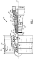
- FIG. 1 schematically illustrates a gas turbine engine 20.
- the gas turbine engine 20 is disclosed herein as a two-spool turbofan that generally incorporates a fan section 22, a compressor section 24, a combustor section 26 and a turbine section 28.
- Alternative engines might include an augmentor section (not shown) among other systems or features.
- the fan section 22 drives air along a bypass flow path B in a bypass duct defined within a nacelle 15, while the compressor section 24 drives air along a core flow path C for compression and communication into the combustor section 26 then expansion through the turbine section 28.
- the exemplary engine 20 generally includes a low speed spool 30 and a high speed spool 32 mounted for rotation about an engine central longitudinal axis A relative to an engine static structure 36 via several bearing systems 38. It should be understood that various bearing systems 38 at various locations may alternatively or additionally be provided, and the location of bearing systems 38 may be varied as appropriate to the application.
- the low speed spool 30 generally includes an inner shaft 40 that interconnects a fan 42, a first (or low) pressure compressor 44 and a first (or low) pressure turbine 46.
- the inner shaft 40 is connected to the fan 42 through a speed change mechanism, which in exemplary gas turbine engine 20 is illustrated as a geared architecture 48 to drive the fan 42 at a lower speed than the low speed spool 30.
- the high speed spool 32 includes an outer shaft 50 that interconnects a second (or high) pressure compressor 52 and a second (or high) pressure turbine 54.
- a combustor 56 is arranged in exemplary gas turbine 20 between the high pressure compressor 52 and the high pressure turbine 54.
- a mid-turbine frame 57 of the engine static structure 36 is arranged generally between the high pressure turbine 54 and the low pressure turbine 46.
- the mid-turbine frame 57 further supports bearing systems 38 in the turbine section 28.
- the inner shaft 40 and the outer shaft 50 are concentric and rotate via bearing systems 38 about the engine central longitudinal axis A which is collinear with their longitudinal axes.
- the core airflow is compressed by the low pressure compressor 44 then the high pressure compressor 52, mixed and burned with fuel in the combustor 56, then expanded over the high pressure turbine 54 and low pressure turbine 46.
- the mid-turbine frame 57 includes airfoils 59 which are in the core airflow path C.
- the turbines 46, 54 rotationally drive the respective low speed spool 30 and high speed spool 32 in response to the expansion.
- gear system 48 may be located aft of combustor section 26 or even aft of turbine section 28, and fan section 22 may be positioned forward or aft of the location of gear system 48.
- a first stage fan 180 delivers air into an outer housing 181.
- the outer housing 181 defines an outer bypass duct 182 outwardly of an inner housing 183.
- the outer bypass duct 182 is alternatively referred to as a "third stream", and air from the outer bypass duct 182 is referred to as third stream air.
- a second stage fan 184 delivers air downstream of the first stage fan 180 into an inner bypass duct 186.
- the inner bypass duct 186 is defined between an inner periphery of the inner housing 183 and an outer periphery of a core housing 187.
- Core housing 187 defines a radially inner extent of inner bypass duct 186.
- Controls 196 and 198 are shown schematically. In one example, the controls are nozzles which control the flow of air through the bypass flow ducts 182 and 186.
- the first stage fan 180 delivers air inwardly of outer housing 181 and inwardly of inner housing 183.
- a second stage fan 184 delivers air inwardly of inner housing 183, but does not deliver air inwardly of the outer housing 181.
- a core engine inlet 188 receives air downstream of the second stage fan 184. That air passes into a compressor 190, a combustor 192 and a turbine 194. It should be understood that the compressor 190 may include multiple rotors and the turbine 194 may also comprise multiple rotors. The turbine rotors drive the compressor 190 and the fan stages 180 and 184.
- the aft stages of the compressor section 24, 190 and the turbine section 28, 194 of a given engine 20 are actively cooled using cooled cooling air sourced at one or more compressor bleeds.
- the cooling air bleed from the compressor section 24, 190 is cooled in a heat exchanger using air from the bypass flowpath B as a heat sink, in the example of Figure 1 , or using air from the third stream 182, in the example of Figure 2 .
- a fraction of air is bled from the compressor section 24, 190 diffuser and cooled in a heat exchanger and is returned to the compressor section 24, 190 and/or the turbine section 28, 194.
- the pressure differential between the cold side of the heat exchanger (the bypass flow path B or the third stream 182) and the compressor bleed can be excessively high.
- the magnitude of cooling required in a single cooling step incurs a large thermal gradient across the heat exchanger.
- the high pressure differential and large thermal gradients places high stresses on the heat exchanger in the cooling step.
- the high stresses in turn, reduce the life cycle of the heat exchanger, require the heat exchanger to be excessively large and heavy to accommodate the higher stresses, or both.
- an example gas turbine engine 200 utilizes a cascaded heat exchanger configuration to provide cooled cooling air to the segments of the engine 200 being actively cooled.
- the example gas turbine engine 200 includes a compressor section 210 having multiple stages 212, a combustor section 220, and a turbine section 230 having multiple stages 232.
- a mid compressor bleed 240 withdraws a first bleed air 241 from a compressor flowpath between compressor stages 212 at approximately midway through the compressor section 210.
- the first bleed air 241 is provided to a first heat exchanger 250.
- Also provided to the heat exchanger 250 is cold air 260 from the bypass flowpath (in the case of a geared turbofan engine) or the third stream (in the case of a multiple bypass flow engine).
- the cold air 260 is used as a heat sink in the first heat exchanger 250 to cool the first bleed air 241.
- the second bleed air 243 is provided to a second heat exchanger 251.
- Also provided to the second heat exchanger 251 is the cooled air output of the first heat exchanger 250.
- the cooled air output of the first heat exchanger 250 is the first bleed air 241.
- the first bleed air 241 acts as a heat sink for the second bleed air 243 in the second heat exchanger 251.
- a third compressor bleed 244 is positioned at an aft end of the compressor section 210.
- the third compressor bleed 244 removes a third bleed air 245 from the compressor flowpath, and provides the third bleed air 245 to a third heat exchanger 252.
- Also provided to the third heat exchanger 252 is the cooled air output of the second heat exchanger 251.
- the cooled air output of the second heat exchanger 251 is the second bleed air 243.
- the second bleed air 243 acts as a heat sink for the third bleed air 245 in the third heat exchanger 252. Once cooled in the third heat exchanger, the third bleed air is returned to the aftmost stage 212 of the compressor section 210 and actively cools the aftmost stage 212.
- the pressure difference between the third bleed air 245 and the compressor flowpath at the point where the third bleed air 245 is returned to the compressor flowpath is minimal.
- the heat sink air from the second heat exchanger 251 is provided to a fourth heat exchanger 253.
- the fourth heat exchanger 253 is provided cold air 260 from the bypass flowpath (in the case of a geared turbofan engine) or the third stream (in the case of a multiple bypass flow engine).
- the cold air 260 cools the heat sink air from the second heat exchanger 251.
- the heat sink air in the first heat exchanger 250 and the fourth heat exchanger 253 is drawn from the same source.
- the first heat exchanger 250 and the fourth heat exchanger 253 can be combined into a single heat exchanger 254.
- the output heat sink air from both the first heat exchanger 250 and the fourth heat exchanger 253, or the combined heat exchanger 254, is returned to the bypass flowpath or the third stream.
- the auxiliary compressor system 270 includes an auxiliary turbine 272 and an auxiliary compressor 274.
- the cooled air output of the fourth heat exchanger 253 (the first bleed air 241) is provided to the turbine 272, and expanded across the auxiliary turbine 272.
- the expansion across the turbine drives rotation of the auxiliary compressor 274.
- the auxiliary compressor 274 receives and compresses at least a portion of the second bleed air 243 after the second bleed air 243 has been utilized as a heat sink in the third heat exchanger 252.
- An auxiliary compressor output 276 is provided as cooled cooling air to the first turbine stage 232.
- a portion of the second bleed air 243 is provided to a second or later stage 232 of the turbine section 230 and provides active cooling. The portion is removed from the second bleed air 243 prior to the second bleed air 243 being provided to the auxiliary compressor 274 at a branch 278.
- a valve 280 controls the amount of air removed from the second bleed air 243 prior to being provided to the auxiliary compressor 274.
- the valve 280 is connected to and controlled by an engine controller 282, or any other similar control device.
- the flow of first bleed air 241 through the auxiliary turbine 272 is controlled via a second valve 284.
- the second valve 284 is also controlled via the engine controller 282.
- Expanded air 273 is output from the auxiliary turbine 272 and returned to an inlet of the compressor section 210, where it is ingested and recompressed through the compressor section 210.
- the gas turbine engine 200 can further include an auxiliary generator 290.
- An exemplary gas turbine engine 200 with the additional inclusion of an auxiliary generator 290 is illustrated in Figure 4 .
- the auxiliary generator 290 is connected to the auxiliary compressor 274, and is driven to rotate by the rotation of the auxiliary compressor 274.
- the rotation of the auxiliary generator 290 generates electrical power according to known electricity generation principles.
- the auxiliary generator 290 can be connected to aircraft electrical systems and provide electrical power to onboard electronic systems.
- the pressure differential between the first bleed air 241 and the heat sink air of the first heat exchanger 250 is relatively small.
- the heat sink configuration is cascaded upward in pressure, while maintaining approximately the same relatively small pressure differential, such that the cooled air in each heat exchanger 250, 251, 252, 253 is cooled by a heat sink air with a relatively small pressure differential.
- the pressure differential in each heat exchanger 250, 251, 252, 253 is approximately the same. This upward cascade in cooling and pressure is referred to as a cascaded cooled cooling air system.
- Figure 5 illustrates an alternate heat exchanger 250 arrangement for providing cascaded cooled cooling air to cool an aft stage of a compressor 310 and at least a first stage of a turbine 330.
- the example gas turbine engine 300 of Figure 5 includes a compressor section 310 having multiple stages 312, a combustor section 320, and a turbine section 330 having multiple stages 332.
- the example gas turbine engine of Figure 5 utilizes a single parallel heat exchanger 350.
- the parallel heat exchanger 350 utilizes parallel flows, where a single flow acts as a heat sink to one adjacent flow and is actively cooled by another adjacent flow.
- the example of Figure 5 utilizes a first compressor bleed 340 at an approximate mid-point in the compressor 310, a second compressor bleed 341 aft of the first compressor bleed 340, and a third compressor bleed aft of the second compressor bleed 341.
- the cooled cooling air for each area in the example of Figure 5 is generated in the same manner as described above with regards to the examples of Figures 3 and 4 .
- an auxiliary compressor system 370 is connected to the outputs of the parallel heat exchanger 350 in the example of Figure 5 .
- the heating and cooling flows through the parallel heat exchanger 350 are cooled via identical heat sinks as the sequential heat exchangers 250, 251, 252, 253 described above with regards to Figure 3 and 4 , and provide for the same heating and cooling generation.
- any number of sequential heat exchangers can be combined into at least one parallel heat exchanger, provided the required heat duties sustain a positive temperature gradient between each adjacent pair of fluids.. Further, the number of sequential heat exchangers and parallel heat exchangers to be used in a given example can be determined based on the available volume, weight limitations, and cooling requirements of any given engine.
- Figure 6 illustrates another example configuration of a cascaded heat exchanger configuration for generating cooled cooling air in a gas turbine engine 400.
- the example of Figure 5 utilizes a first compressor bleed 440 at an approximate mid-point in the compressor 410, a second compressor bleed 441 aft of the first compressor bleed 440, and a third compressor bleed 442 aft of the second compressor bleed 441.
- a first heat exchanger 450 and a fourth heat exchanger 453 utilize air from the bypass duct or the third stream as a heat sink.
- the first heat exchanger 450 receives air from the first compressor bleed 440 and cools the air using the heat sink air.
- the cooled first bleed air 441 is provided as a heat sink in a parallel heat exchanger 451.
- the parallel heat exchanger 451 receives the second bleed air 443 and the third bleed air 444.
- the second bleed air 443 is simultaneously cooled by the first bleed air 441 and cools the third bleed air 444.
- Each of the outputs of the parallel heat exchanger 451 is provided to an auxiliary compressor system 470. The remainder of the features and connections are substantially similar to the features illustrated in Figures 3 and 4 and described above.
- Figure 7 illustrates a modification that can be applied to the gas turbine engine 200 in an example gas turbine engine 600.
- the heat exchangers 650, 651, 652, 653 are arranged in the same sequential cascading manner as in the example of Figure 3 .
- the example of Figure 7 includes multiple diverter valves 691, 692.
- the diverter valves 691, 692 enable an increased power extraction from the auxiliary turbine 672.
- the fourth heat exchanger 653 can be partially or wholly bypassed such that an inlet temperature of the auxiliary turbine 672 is higher. Higher inlet temperatures increase the power output from the auxiliary turbine utilized to drive the auxiliary compressor 674 and an attached generator 690.
- the second diverter valve 691 shunts auxiliary turbine discharge from the auxiliary turbine 672 to the fan bypass stream (in the case of an engine according to Figure 1 ) or the third stream (in the case of an engine according to Figure 2 ).
- the fan bypass stream or the third stream is at a lower pressure than the inlet to the core compressor.
- the expansion across the auxiliary turbine 672 is increased to expand the cooled air to match the inlet pressure of the bypass flow or the third duct flow, allowing the auxiliary turbine to extract more work from the cooled air.
- each of the heat exchangers and the auxiliary compressor system can be positioned in a core cowling that surrounds the compressor, combustor, and turbine sections of the gas turbine engine.
- the heat exchangers, auxiliary compressor system, generator, or any other elements can be disposed in any other location within the gas turbine engine.
Abstract
Description
- The present disclosure relates generally to gas turbine engines, and more specifically to a cooled cooling air system for a gas turbine engine.
- Gas turbine engines, such as those utilized on commercial and military aircraft, include a compressor section that draws in air, a combustor section that mixes the compressed air with a fuel, and ignites the mixture, and a turbine section across which the results of the combustion are expanded. The expansion across the turbine section drives the turbine section to rotate, which in turn drives rotation of the compressor.
- In some example engines, this configuration results in excess heat at the aft stages of the compressor section and in the turbine section. In order to prevent the excess heat from damaging engine components, or reducing the lifecycle of engine components, portions of the compressor section and the turbine section are actively cooled using cooled cooling air.
- In one exemplary embodiment a gas turbine engine includes a compressor section, a combustor fluidly connected to the compressor section via a primary flowpath, a turbine section fluidly connected to the combustor via the primary flowpath, and a cascading cooling system having a first inlet connected to a first compressor bleed, a second inlet connected to a second compressor bleed downstream of the first compressor bleed, and a third inlet connected to a third compressor bleed downstream of the second compressor bleed. The cascading cooling system includes at least one heat exchanger configured to incrementally generate cooling air for at least one of an aft compressor stage and a foremost turbine stage relative to fluid flow through the turbine section.
- In another exemplary embodiment of the above described gas turbine engine, the third compressor bleed is at an outlet of the compressor section.
- In another exemplary embodiment of any of the above described gas turbine engines, the at least one heat exchanger includes a first heat exchanger, a second heat exchanger in series with the first heat exchanger, and a third heat exchanger in series with the second heat exchanger.
- In another exemplary embodiment of any of the above described gas turbine engines, a heat sink input of the second heat exchanger is a cooled flow output of the first heat exchanger and originates at the first inlet, and wherein a heat sink input of the third heat exchanger is a cooled flow output of the second heat exchanger and originates at the second inlet.
- In another exemplary embodiment of any of the above described gas turbine engines, a cooled flow output of the third heat exchanger is provided to an aft most compressor stage as a cooled cooling flow and originates at the third inlet.
- In another exemplary embodiment of any of the above described gas turbine engines, the at least one heat exchanger includes a parallel heat exchanger having at least a first heat sink input, a first cooled flow input and a second cooled flow input, and wherein fluid passing through the first cooled flow input is simultaneously cooled by the first heat sink input and cools the second cooled flow input.
- In another exemplary embodiment of any of the above described gas turbine engines, the at least one heat exchanger further includes a third cooled flow input, and fluid passing through the second cooled flow input is simultaneously cooled by the first cooled flow input and cools the third cooled flow input.
- In another exemplary embodiment of any of the above described gas turbine engines, the third cooled flow input is returned to an aft most compressor stage as a cooled cooling flow.
- Another exemplary embodiment of any of the above described gas turbine engines further includes an auxiliary compressor system having an auxiliary turbine connected to an auxiliary compressor such that rotation of the auxiliary turbine drives rotation of the auxiliary compressor, and wherein an input of the auxiliary turbine is connected to a heat sink outlet of a third heat exchanger such that cooling air originating at the second compressor bleed is compressed in the auxiliary compressor.
- In another exemplary embodiment of any of the above described gas turbine engines, an output of the auxiliary compressor system is provided to a foremost stage of the turbine section as cooled cooling air.
- In another exemplary embodiment of any of the above described gas turbine engines, an input of the auxiliary turbine is at least one of an output heat sink air of a second heat exchanger, and an output heat sink air of a fourth heat exchanger, and wherein an output of the auxiliary turbine is returned to a compressor section inlet.
- In another exemplary embodiment of any of the above described gas turbine engines, the input of the auxiliary turbine is a combination of a heat sink output of the second heat exchanger, and a heat sink output of the fourth heat exchanger, and wherein the combination is controlled by a modulation valve.
- In another exemplary embodiment of any of the above described gas turbine engines, fluid flow through the auxiliary turbine is at least partially controlled by a modulation valve downstream of an auxiliary turbine outlet, and wherein fluid flow to the inlet of the auxiliary compressor is at least partially controlled by a modulation valve connecting the heat sink outlet of the third heat exchanger to a second or later stage of the turbine section.
- In another exemplary embodiment of any of the above described gas turbine engines, each of the modulation valves is controlled by at least one controller.
- In another exemplary embodiment of any of the above described gas turbine engines, the gas turbine engine is a geared turbofan engine.
- In another exemplary embodiment of any of the above described gas turbine engines, the gas turbine engine is a multiple bypass flow engine.
- An exemplary method for generating cooled cooling air in a gas turbine engine includes providing air from a plurality of compressor bleeds as inputs to a cascading heat exchanger, incrementally cooling air received via the inputs such that a first of the inputs is a heat sink for a second of the inputs, and the second of the inputs is a heat sink for a third of the inputs, and actively cooling at least one of an aft most compressor stage and a fore most turbine stage using cooled cooling air output from the cascading heat exchanger.
- In a further example of the above described exemplary method for generating cooled cooling air in a gas turbine engine, incrementally cooling air received via the inputs includes cooling the air using a plurality of serially arranged heat exchangers, each of the serially arranged heat exchangers increasing a pressure of cooled output air relative to a serially previous heat exchanger.
- In a further example of any of the above described exemplary methods for generating cooled cooling air in a gas turbine engine, incrementally cooling air received via the inputs includes cooling the air using at least one parallel heat exchanger configured such that air from at least one of the inputs simultaneously cools an adjacent air flow and is cooled by another adjacent airflow.
- In one exemplary embodiment a gas turbine engine includes a compressor section, a combustor fluidly connected to the compressor section via a primary flowpath, a turbine section fluidly connected to the combustor via the primary flowpath, and a cascading cooling system having a plurality of inlets, each of the inlets connected to one of a plurality of compressor bleeds. The cascading cooling system includes at least one heat exchanger configured to incrementally generate a cooled cooling air across a plurality of stages, each of the stages having approximately the same pressure differential as each other of the stages.
- These and other features of the present invention can be best understood from the following specification and drawings, the following of which is a brief description.
-
-
Figure 1 schematically illustrates a first exemplary gas turbine engine. -
Figure 2 schematically illustrates a second exemplary gas turbine engine. -
Figure 3 schematically illustrates a first example cooled cooling air system for a gas turbine engine. -
Figure 4 schematically illustrates the first example cooled cooling air system for a gas turbine engine with the addition of an auxiliary generator. -
Figure 5 schematically illustrates a second example cooled cooling air system for a gas turbine engine. -
Figure 6 schematically illustrates a third example cooled cooling air system for a gas turbine engine. -
Figure 7 schematically illustrates a fourth example cooled cooling air system for a gas turbine engine. -
Figure 1 schematically illustrates agas turbine engine 20. Thegas turbine engine 20 is disclosed herein as a two-spool turbofan that generally incorporates a fan section 22, a compressor section 24, acombustor section 26 and a turbine section 28. Alternative engines might include an augmentor section (not shown) among other systems or features. The fan section 22 drives air along a bypass flow path B in a bypass duct defined within anacelle 15, while the compressor section 24 drives air along a core flow path C for compression and communication into thecombustor section 26 then expansion through the turbine section 28. Although depicted as a two-spool turbofan gas turbine engine in the disclosed non-limiting embodiment, it should be understood that the concepts described herein are not limited to use with two-spool turbofans as the teachings may be applied to other types of turbine engines including three-spool architectures. - The
exemplary engine 20 generally includes a low speed spool 30 and a high speed spool 32 mounted for rotation about an engine central longitudinal axis A relative to an enginestatic structure 36 viaseveral bearing systems 38. It should be understood thatvarious bearing systems 38 at various locations may alternatively or additionally be provided, and the location ofbearing systems 38 may be varied as appropriate to the application. - The low speed spool 30 generally includes an
inner shaft 40 that interconnects afan 42, a first (or low) pressure compressor 44 and a first (or low)pressure turbine 46. Theinner shaft 40 is connected to thefan 42 through a speed change mechanism, which in exemplarygas turbine engine 20 is illustrated as a gearedarchitecture 48 to drive thefan 42 at a lower speed than the low speed spool 30. The high speed spool 32 includes anouter shaft 50 that interconnects a second (or high)pressure compressor 52 and a second (or high)pressure turbine 54. Acombustor 56 is arranged inexemplary gas turbine 20 between thehigh pressure compressor 52 and thehigh pressure turbine 54. A mid-turbine frame 57 of the enginestatic structure 36 is arranged generally between thehigh pressure turbine 54 and thelow pressure turbine 46. The mid-turbine frame 57 further supports bearingsystems 38 in the turbine section 28. Theinner shaft 40 and theouter shaft 50 are concentric and rotate viabearing systems 38 about the engine central longitudinal axis A which is collinear with their longitudinal axes. - The core airflow is compressed by the low pressure compressor 44 then the
high pressure compressor 52, mixed and burned with fuel in thecombustor 56, then expanded over thehigh pressure turbine 54 andlow pressure turbine 46. The mid-turbine frame 57 includesairfoils 59 which are in the core airflow path C. Theturbines combustor section 26, turbine section 28, and fandrive gear system 48 may be varied. For example,gear system 48 may be located aft ofcombustor section 26 or even aft of turbine section 28, and fan section 22 may be positioned forward or aft of the location ofgear system 48. - With regards to engines for military applications, there has recently been provision of multiple bypass flow engines. An example multiple bypass flow engine is shown schematically in
Figure 2 . Afirst stage fan 180 delivers air into anouter housing 181. Theouter housing 181 defines anouter bypass duct 182 outwardly of aninner housing 183. Theouter bypass duct 182 is alternatively referred to as a "third stream", and air from theouter bypass duct 182 is referred to as third stream air. Asecond stage fan 184 delivers air downstream of thefirst stage fan 180 into aninner bypass duct 186. Theinner bypass duct 186 is defined between an inner periphery of theinner housing 183 and an outer periphery of acore housing 187.Core housing 187 defines a radially inner extent ofinner bypass duct 186.Controls bypass flow ducts - The
first stage fan 180 delivers air inwardly ofouter housing 181 and inwardly ofinner housing 183. Asecond stage fan 184 delivers air inwardly ofinner housing 183, but does not deliver air inwardly of theouter housing 181. - A
core engine inlet 188 receives air downstream of thesecond stage fan 184. That air passes into acompressor 190, acombustor 192 and aturbine 194. It should be understood that thecompressor 190 may include multiple rotors and theturbine 194 may also comprise multiple rotors. The turbine rotors drive thecompressor 190 and the fan stages 180 and 184. - In some examples, the aft stages of the
compressor section 24, 190 and theturbine section 28, 194 of a givenengine 20 are actively cooled using cooled cooling air sourced at one or more compressor bleeds. The cooling air bleed from thecompressor section 24, 190 is cooled in a heat exchanger using air from the bypass flowpath B as a heat sink, in the example ofFigure 1 , or using air from thethird stream 182, in the example ofFigure 2 . A fraction of air is bled from thecompressor section 24, 190 diffuser and cooled in a heat exchanger and is returned to thecompressor section 24, 190 and/or theturbine section 28, 194. - When the air is fully cooled in a single step, the pressure differential between the cold side of the heat exchanger (the bypass flow path B or the third stream 182) and the compressor bleed can be excessively high. Further, the magnitude of cooling required in a single cooling step incurs a large thermal gradient across the heat exchanger. The high pressure differential and large thermal gradients places high stresses on the heat exchanger in the cooling step. The high stresses in turn, reduce the life cycle of the heat exchanger, require the heat exchanger to be excessively large and heavy to accommodate the higher stresses, or both.
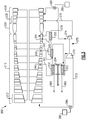
- In order to minimize the weight requirements and the thermal stresses on the heat exchanger, an example
gas turbine engine 200, schematically illustrated inFigure 3 , utilizes a cascaded heat exchanger configuration to provide cooled cooling air to the segments of theengine 200 being actively cooled. The examplegas turbine engine 200 includes acompressor section 210 havingmultiple stages 212, acombustor section 220, and aturbine section 230 havingmultiple stages 232. - A
mid compressor bleed 240 withdraws afirst bleed air 241 from a compressor flowpath betweencompressor stages 212 at approximately midway through thecompressor section 210. Thefirst bleed air 241 is provided to afirst heat exchanger 250. Also provided to theheat exchanger 250 iscold air 260 from the bypass flowpath (in the case of a geared turbofan engine) or the third stream (in the case of a multiple bypass flow engine). Thecold air 260 is used as a heat sink in thefirst heat exchanger 250 to cool thefirst bleed air 241. - A
second compressor bleed 242, aft of themid compressor bleed 240, withdraws asecond bleed air 243 from between compressor stages 212. Thesecond bleed air 243 is provided to a second heat exchanger 251. Also provided to the second heat exchanger 251 is the cooled air output of thefirst heat exchanger 250. The cooled air output of thefirst heat exchanger 250 is thefirst bleed air 241. Thefirst bleed air 241 acts as a heat sink for thesecond bleed air 243 in the second heat exchanger 251. - A
third compressor bleed 244 is positioned at an aft end of thecompressor section 210. Thethird compressor bleed 244 removes a third bleed air 245 from the compressor flowpath, and provides the third bleed air 245 to a third heat exchanger 252. Also provided to the third heat exchanger 252 is the cooled air output of the second heat exchanger 251. The cooled air output of the second heat exchanger 251 is thesecond bleed air 243. Thesecond bleed air 243 acts as a heat sink for the third bleed air 245 in the third heat exchanger 252. Once cooled in the third heat exchanger, the third bleed air is returned to theaftmost stage 212 of thecompressor section 210 and actively cools theaftmost stage 212. Because the third bleed air 245 is pulled from athird compressor bleed 244 at the aftmost stage, the pressure difference between the third bleed air 245 and the compressor flowpath at the point where the third bleed air 245 is returned to the compressor flowpath is minimal. - The heat sink air from the second heat exchanger 251 is provided to a
fourth heat exchanger 253. As with thefirst heat exchanger 250, thefourth heat exchanger 253 is providedcold air 260 from the bypass flowpath (in the case of a geared turbofan engine) or the third stream (in the case of a multiple bypass flow engine). Thecold air 260 cools the heat sink air from the second heat exchanger 251. - The heat sink air in the
first heat exchanger 250 and thefourth heat exchanger 253 is drawn from the same source. As a result, in some configurations, thefirst heat exchanger 250 and thefourth heat exchanger 253 can be combined into asingle heat exchanger 254. The output heat sink air from both thefirst heat exchanger 250 and thefourth heat exchanger 253, or the combinedheat exchanger 254, is returned to the bypass flowpath or the third stream. - Also included within the
gas turbine engine 200 is anauxiliary compressor system 270. Theauxiliary compressor system 270 includes anauxiliary turbine 272 and anauxiliary compressor 274. The cooled air output of the fourth heat exchanger 253 (the first bleed air 241) is provided to theturbine 272, and expanded across theauxiliary turbine 272. The expansion across the turbine drives rotation of theauxiliary compressor 274. Theauxiliary compressor 274, in turn, receives and compresses at least a portion of thesecond bleed air 243 after thesecond bleed air 243 has been utilized as a heat sink in the third heat exchanger 252. - An
auxiliary compressor output 276 is provided as cooled cooling air to thefirst turbine stage 232. In some example cooling systems, a portion of thesecond bleed air 243 is provided to a second or later stage 232 of theturbine section 230 and provides active cooling. The portion is removed from thesecond bleed air 243 prior to thesecond bleed air 243 being provided to theauxiliary compressor 274 at abranch 278. Avalve 280 controls the amount of air removed from thesecond bleed air 243 prior to being provided to theauxiliary compressor 274. Thevalve 280 is connected to and controlled by anengine controller 282, or any other similar control device. - In some examples, the flow of
first bleed air 241 through theauxiliary turbine 272 is controlled via asecond valve 284. Thesecond valve 284 is also controlled via theengine controller 282.Expanded air 273 is output from theauxiliary turbine 272 and returned to an inlet of thecompressor section 210, where it is ingested and recompressed through thecompressor section 210. - In some examples, the
gas turbine engine 200 can further include an auxiliary generator 290. An exemplarygas turbine engine 200 with the additional inclusion of an auxiliary generator 290 is illustrated inFigure 4 . The auxiliary generator 290 is connected to theauxiliary compressor 274, and is driven to rotate by the rotation of theauxiliary compressor 274. The rotation of the auxiliary generator 290 generates electrical power according to known electricity generation principles. The auxiliary generator 290 can be connected to aircraft electrical systems and provide electrical power to onboard electronic systems. - With continued reference to
Figures 3 and4 , the pressure differential between thefirst bleed air 241 and the heat sink air of thefirst heat exchanger 250 is relatively small. The heat sink configuration is cascaded upward in pressure, while maintaining approximately the same relatively small pressure differential, such that the cooled air in eachheat exchanger heat exchanger - With continued reference to
Figures 3 and4 ,Figure 5 illustrates analternate heat exchanger 250 arrangement for providing cascaded cooled cooling air to cool an aft stage of acompressor 310 and at least a first stage of aturbine 330. As with the example ofFigures 3 and4 , the examplegas turbine engine 300 ofFigure 5 includes acompressor section 310 havingmultiple stages 312, acombustor section 320, and aturbine section 330 havingmultiple stages 332. In place of the first, second, third andfourth heat exchangers Figures 3 and4 , the example gas turbine engine ofFigure 5 utilizes a singleparallel heat exchanger 350. Theparallel heat exchanger 350 utilizes parallel flows, where a single flow acts as a heat sink to one adjacent flow and is actively cooled by another adjacent flow. - As with the examples of
Figures 3 and4 , the example ofFigure 5 utilizes afirst compressor bleed 340 at an approximate mid-point in thecompressor 310, asecond compressor bleed 341 aft of thefirst compressor bleed 340, and a third compressor bleed aft of thesecond compressor bleed 341. The cooled cooling air for each area in the example ofFigure 5 is generated in the same manner as described above with regards to the examples ofFigures 3 and4 . Similarly, anauxiliary compressor system 370 is connected to the outputs of theparallel heat exchanger 350 in the example ofFigure 5 . - The heating and cooling flows through the
parallel heat exchanger 350 are cooled via identical heat sinks as thesequential heat exchangers Figure 3 and4 , and provide for the same heating and cooling generation. One of skill in the art, having the benefit of this disclosure, will understand that any number of sequential heat exchangers can be combined into at least one parallel heat exchanger, provided the required heat duties sustain a positive temperature gradient between each adjacent pair of fluids.. Further, the number of sequential heat exchangers and parallel heat exchangers to be used in a given example can be determined based on the available volume, weight limitations, and cooling requirements of any given engine. - With continued reference to
Figures 3 and4 ,Figure 6 illustrates another example configuration of a cascaded heat exchanger configuration for generating cooled cooling air in agas turbine engine 400. The example ofFigure 5 utilizes afirst compressor bleed 440 at an approximate mid-point in thecompressor 410, asecond compressor bleed 441 aft of thefirst compressor bleed 440, and a third compressor bleed 442 aft of thesecond compressor bleed 441. As with the examples ofFigures 3 and4 , a first heat exchanger 450 and a fourth heat exchanger 453 utilize air from the bypass duct or the third stream as a heat sink. The first heat exchanger 450 receives air from thefirst compressor bleed 440 and cools the air using the heat sink air. - The cooled
first bleed air 441 is provided as a heat sink in aparallel heat exchanger 451. Theparallel heat exchanger 451 receives the second bleed air 443 and thethird bleed air 444. The second bleed air 443 is simultaneously cooled by thefirst bleed air 441 and cools thethird bleed air 444. Each of the outputs of theparallel heat exchanger 451 is provided to anauxiliary compressor system 470. The remainder of the features and connections are substantially similar to the features illustrated inFigures 3 and4 and described above. - With continued reference to
Figures 3 and4 ,Figure 7 illustrates a modification that can be applied to thegas turbine engine 200 in an examplegas turbine engine 600. Theheat exchangers Figure 3 . In addition to the heat sink flows, and cooled air flows ofFigures 3 and4 , the example ofFigure 7 includesmultiple diverter valves diverter valves auxiliary turbine 672. Thefourth heat exchanger 653 can be partially or wholly bypassed such that an inlet temperature of theauxiliary turbine 672 is higher. Higher inlet temperatures increase the power output from the auxiliary turbine utilized to drive theauxiliary compressor 674 and an attachedgenerator 690. - Further, the
second diverter valve 691 shunts auxiliary turbine discharge from theauxiliary turbine 672 to the fan bypass stream (in the case of an engine according toFigure 1 ) or the third stream (in the case of an engine according toFigure 2 ). The fan bypass stream or the third stream is at a lower pressure than the inlet to the core compressor. The expansion across theauxiliary turbine 672 is increased to expand the cooled air to match the inlet pressure of the bypass flow or the third duct flow, allowing the auxiliary turbine to extract more work from the cooled air. - With reference to
Figures 3-7 , the illustrated heat exchangers and cooled cooling air systems can be located in any physical location within a gas turbine engine, subject to design restraints. By way of example, each of the heat exchangers and the auxiliary compressor system can be positioned in a core cowling that surrounds the compressor, combustor, and turbine sections of the gas turbine engine. In alternative examples, the heat exchangers, auxiliary compressor system, generator, or any other elements, can be disposed in any other location within the gas turbine engine. - It is further understood that any of the above described concepts can be used alone or in combination with any or all of the other above described concepts. Although an embodiment of this invention has been disclosed, a worker of ordinary skill in this art would recognize that certain modifications would come within the scope of this invention. For that reason, the following claims should be studied to determine the true scope and content of this invention.
Claims (15)
- A gas turbine engine (20;200;300;400;600) comprising:a compressor section (24;190;210;310;410;610);a combustor (26;192;220;320;420;620) fluidly connected to the compressor section (24;...610) via a primary flowpath;a turbine (28;194;230;330;430;630) section fluidly connected to the combustor (26;...620) via the primary flowpath;a cascading cooling system having a first inlet connected to a first compressor bleed (240;340;440;640), a second inlet connected to a second compressor bleed (242;342;442;642) downstream of the first compressor bleed (240;340;440;640), and a third inlet connected to a third compressor bleed (244;344;444;644) downstream of the second compressor bleed (242;...642);the cascading cooling system including at least one heat exchanger (250,251,252,253;350;450,451,453;650,651,652,653) configured to incrementally generate cooling air for at least one of an aft compressor stage and a foremost turbine stage relative to fluid flow through the turbine section (28;...630).
- The gas turbine engine (20;...600) of claim 1, wherein the third compressor bleed (244;...644) is at an outlet of the compressor section (24;...610).
- The gas turbine engine (20;200;600) of claim 1 or 2, wherein the at least one heat exchanger (250,251,252,253;650,651,652,653) includes a first heat exchanger (250;650), a second heat exchanger (251;651) in series with the first heat exchanger (250;650), and a third heat exchanger (252;652) in series with the second heat exchanger (251;651).
- The gas turbine engine (20;200;600) of claim 3, wherein a heat sink input of the second heat exchanger (251;651) is a cooled flow output of the first heat exchanger (250;650) and originates at the first inlet, and wherein a heat sink input of the third heat exchanger (252;652) is a cooled flow output of the second heat exchanger (251;651) and originates at the second inlet and wherein, optionally, a cooled flow output of the third heat exchanger (252;652) is provided to an aft most compressor stage as a cooled cooling flow and originates at the third inlet.
- The gas turbine engine (20;300;400) of claim 1 or 2, wherein the at least one heat exchanger (350;450;451;453) includes a parallel heat exchanger (350;451) having at least a first heat sink input, a first cooled flow input and a second cooled flow input, and wherein fluid passing through the first cooled flow input is simultaneously cooled by said first heat sink input and cools said second cooled flow input.
- The gas turbine engine (20;300;400) of claim 5, wherein the at least one heat exchanger (350;450;451;453) further includes a third cooled flow input, and fluid passing through the second cooled flow input is simultaneously cooled by said first cooled flow input and cools said third cooled flow input and wherein, optionally, said third cooled flow input is returned to an aft most compressor stage as a cooled cooling flow.
- The gas turbine engine (20;...600) of any preceding claim further comprising an auxiliary compressor system (270;370;470) having an auxiliary turbine (272;672) connected to an auxiliary compressor (274;674) such that rotation of the auxiliary turbine (272;672) drives rotation of the auxiliary compressor (274;674), and wherein an input of the auxiliary turbine (272;672) is connected to a heat sink outlet of a third heat exchanger (253;350;453;653) such that cooling air originating at the second compressor bleed (242;...642) is compressed in the auxiliary compressor (274;674).
- The gas turbine engine (20;...600) of claim 7, wherein an output of the auxiliary compressor system (274;674) is provided to a foremost stage of the turbine section as cooled cooling air.
- The gas turbine engine (20;... 600) of claim 7 or 8, wherein an input of the auxiliary turbine (272;672) is at least one of an output heat sink air of a second heat exchanger (350;651), and an output heat sink air of a fourth heat exchanger (253;350;453;653), and wherein an output of the auxiliary turbine (272;672) is returned to a compressor section inlet.
- The gas turbine engine (20;600) of claim 9, wherein the input of the auxiliary turbine (672) is a combination of a heat sink output of said second heat exchanger (651), and a heat sink output of said fourth heat exchanger (653), and wherein the combination is controlled by a modulation valve (692).
- The gas turbine engine (20;200;300;600) of any of claims 7 to 10, wherein fluid flow through said auxiliary turbine (272;672) is at least partially controlled by a modulation valve (284) downstream of an auxiliary turbine outlet, and wherein fluid flow to said inlet of said auxiliary compressor (274;674) is at least partially controlled by a modulation valve (280) connecting the heat sink outlet of said third heat exchanger (252;350;652) to a second or later stage of said turbine section (28;194;230;330;630).
- The gas turbine engine (20;...600) of any preceding claim , wherein the gas turbine engine (20;...600) is:a geared turbofan engine; and/ora multiple bypass flow engine
- A method for generating cooled cooling air in a gas turbine engine (20;...600) comprising:providing air from a plurality of compressor bleeds (240,242,244;340,342,344;440,442,444;640,642,644) as inputs to a cascading heat exchanger;incrementally cooling air received via said inputs such that a first of said inputs is a heat sink for a second of said inputs, and the second of said inputs is a heat sink for a third of said inputs; andactively cooling at least one of an aft most compressor stage and a fore most turbine stage using cooled cooling air output from said cascading heat exchanger.
- The method of claim 13, wherein incrementally cooling air received via said inputs comprises cooling said air using a plurality of serially arranged heat exchangers (250,251,252;450,451;650,651,652), each of the serially arranged heat exchangers (250;...652) increasing a pressure of cooled output air relative to a serially previous heat exchanger (250;...652).
- The method of claim 13 or 14, wherein incrementally cooling air received via said inputs comprises cooling said air using at least one parallel heat exchanger (350;451) configured such that air from at least one of said inputs simultaneously cools an adjacent air flow and is cooled by another adjacent airflow.
Applications Claiming Priority (1)
| Application Number | Priority Date | Filing Date | Title |
|---|---|---|---|
| US14/714,554 US10100739B2 (en) | 2015-05-18 | 2015-05-18 | Cooled cooling air system for a gas turbine engine |
Publications (2)
| Publication Number | Publication Date |
|---|---|
| EP3095990A1 true EP3095990A1 (en) | 2016-11-23 |
| EP3095990B1 EP3095990B1 (en) | 2020-12-02 |
Family
ID=56120906
Family Applications (1)
| Application Number | Title | Priority Date | Filing Date |
|---|---|---|---|
| EP16170021.6A Active EP3095990B1 (en) | 2015-05-18 | 2016-05-17 | Gas turbine engine and method of operating the same |
Country Status (2)
| Country | Link |
|---|---|
| US (2) | US10100739B2 (en) |
| EP (1) | EP3095990B1 (en) |
Cited By (1)
| Publication number | Priority date | Publication date | Assignee | Title |
|---|---|---|---|---|
| EP3348812A1 (en) * | 2017-01-17 | 2018-07-18 | United Technologies Corporation | Cooled gas turbine engine cooling air with cold air dump |
Families Citing this family (15)
| Publication number | Priority date | Publication date | Assignee | Title |
|---|---|---|---|---|
| EP3168431A1 (en) * | 2015-11-13 | 2017-05-17 | General Electric Technology GmbH | Heat exchangers and cooling methods for gas turbines |
| US10443508B2 (en) * | 2015-12-14 | 2019-10-15 | United Technologies Corporation | Intercooled cooling air with auxiliary compressor control |
| USD795787S1 (en) * | 2016-02-19 | 2017-08-29 | Neva Aerospace Limited | Turbine |
| US11073085B2 (en) * | 2016-11-08 | 2021-07-27 | Raytheon Technologies Corporation | Intercooled cooling air heat exchanger arrangement |
| US11725584B2 (en) | 2018-01-17 | 2023-08-15 | General Electric Company | Heat engine with heat exchanger |
| WO2020005220A1 (en) * | 2018-06-27 | 2020-01-02 | Mitsubishi Hitachi Power Systems Americas, Inc. | Organic rankine cycle for combined-cycle power plant |
| US11066999B2 (en) | 2019-01-16 | 2021-07-20 | Raytheon Technologies Corporation | Fuel cooled cooling air |
| JP7349266B2 (en) * | 2019-05-31 | 2023-09-22 | 三菱重工業株式会社 | Gas turbine and its control method and combined cycle plant |
| US11434824B2 (en) * | 2021-02-03 | 2022-09-06 | General Electric Company | Fuel heater and energy conversion system |
| US11788470B2 (en) | 2021-03-01 | 2023-10-17 | General Electric Company | Gas turbine engine thermal management |
| US11591965B2 (en) | 2021-03-29 | 2023-02-28 | General Electric Company | Thermal management system for transferring heat between fluids |
| US11674396B2 (en) | 2021-07-30 | 2023-06-13 | General Electric Company | Cooling air delivery assembly |
| US11920500B2 (en) | 2021-08-30 | 2024-03-05 | General Electric Company | Passive flow modulation device |
| US11702958B2 (en) | 2021-09-23 | 2023-07-18 | General Electric Company | System and method of regulating thermal transport bus pressure |
| US11692448B1 (en) | 2022-03-04 | 2023-07-04 | General Electric Company | Passive valve assembly for a nozzle of a gas turbine engine |
Citations (6)
| Publication number | Priority date | Publication date | Assignee | Title |
|---|---|---|---|---|
| JPH1136889A (en) * | 1997-07-15 | 1999-02-09 | Mitsubishi Heavy Ind Ltd | Gas turbine cooler |
| US5918458A (en) * | 1997-02-14 | 1999-07-06 | General Electric Company | System and method of providing clean filtered cooling air to a hot portion of a gas turbine engine |
| US6487863B1 (en) * | 2001-03-30 | 2002-12-03 | Siemens Westinghouse Power Corporation | Method and apparatus for cooling high temperature components in a gas turbine |
| US20120180509A1 (en) * | 2011-01-14 | 2012-07-19 | Hamilton Sundstrand Corporation | Low pressure bleed architecture |
| US20130036747A1 (en) * | 2011-06-16 | 2013-02-14 | Alstom Technology Ltd | Method for cooling a gas turbine plant and gas turbine plant for implementing the method |
| US20140311157A1 (en) * | 2012-12-19 | 2014-10-23 | Vincent P. Laurello | Vane carrier temperature control system in a gas turbine engine |
Family Cites Families (142)
| Publication number | Priority date | Publication date | Assignee | Title |
|---|---|---|---|---|
| US2692476A (en) | 1950-11-13 | 1954-10-26 | Boeing Co | Gas turbine engine air starting motor constituting air supply mechanism |
| GB1244340A (en) | 1968-12-23 | 1971-08-25 | Rolls Royce | Front fan gas turbine engine |
| US3878677A (en) | 1974-04-10 | 1975-04-22 | United Aircraft Corp | Auxiliary turbine/compressor system for turbine engine |
| US4254618A (en) | 1977-08-18 | 1981-03-10 | General Electric Company | Cooling air cooler for a gas turbofan engine |
| JPS5477820A (en) | 1977-12-02 | 1979-06-21 | Hitachi Ltd | Method of cooling gas turbine blade |
| IT8322002V0 (en) | 1983-05-31 | 1983-05-31 | Same Spa | INTERNAL COMBUSTION ENGINE GROUP WITH INJECTION PUMP VENTILATION SYSTEM. |
| US4561246A (en) | 1983-12-23 | 1985-12-31 | United Technologies Corporation | Bearing compartment for a gas turbine engine |
| US4882902A (en) | 1986-04-30 | 1989-11-28 | General Electric Company | Turbine cooling air transferring apparatus |
| DE59102139D1 (en) | 1990-03-23 | 1994-08-18 | Asea Brown Boveri | Axial gas turbine. |
| US5056335A (en) | 1990-04-02 | 1991-10-15 | General Electric Company | Auxiliary refrigerated air system employing input air from turbine engine compressor after bypassing and conditioning within auxiliary system |
| US5123242A (en) | 1990-07-30 | 1992-06-23 | General Electric Company | Precooling heat exchange arrangement integral with mounting structure fairing of gas turbine engine |
| US5269135A (en) | 1991-10-28 | 1993-12-14 | General Electric Company | Gas turbine engine fan cooled heat exchanger |
| US5392614A (en) | 1992-03-23 | 1995-02-28 | General Electric Company | Gas turbine engine cooling system |
| US5305616A (en) | 1992-03-23 | 1994-04-26 | General Electric Company | Gas turbine engine cooling system |
| US5414992A (en) * | 1993-08-06 | 1995-05-16 | United Technologies Corporation | Aircraft cooling method |
| US5452573A (en) | 1994-01-31 | 1995-09-26 | United Technologies Corporation | High pressure air source for aircraft and engine requirements |
| US5498126A (en) | 1994-04-28 | 1996-03-12 | United Technologies Corporation | Airfoil with dual source cooling |
| DE19531562A1 (en) | 1995-08-28 | 1997-03-06 | Abb Management Ag | Process for operating a power plant |
| US5724806A (en) | 1995-09-11 | 1998-03-10 | General Electric Company | Extracted, cooled, compressed/intercooled, cooling/combustion air for a gas turbine engine |
| GB9606546D0 (en) | 1996-03-28 | 1996-06-05 | Rolls Royce Plc | Gas turbine engine system |
| JPH1193694A (en) | 1997-09-18 | 1999-04-06 | Toshiba Corp | Gas turbine plant |
| US6430931B1 (en) | 1997-10-22 | 2002-08-13 | General Electric Company | Gas turbine in-line intercooler |
| US6065282A (en) | 1997-10-29 | 2000-05-23 | Mitsubishi Heavy Industries, Ltd. | System for cooling blades in a gas turbine |
| US6050079A (en) | 1997-12-24 | 2000-04-18 | General Electric Company | Modulated turbine cooling system |
| US6134880A (en) | 1997-12-31 | 2000-10-24 | Concepts Eti, Inc. | Turbine engine with intercooler in bypass air passage |
| AU1177100A (en) | 1999-11-10 | 2001-06-06 | Hitachi Limited | Gas turbine equipment and gas turbine cooling method |
| DE10001112A1 (en) | 2000-01-13 | 2001-07-19 | Alstom Power Schweiz Ag Baden | Cooling air cooler for gas turbine unit, with water separator on cooling air side behind jet device in flow direction |
| DE10009655C1 (en) | 2000-02-29 | 2001-05-23 | Mtu Aero Engines Gmbh | Air cooling system for the paddles of a high pressure gas turbine has flow chambers at each paddle for the leading and trailing edges and the center profile with a heat exchanger to cool the air flow to the paddle edges |
| DE10122695A1 (en) | 2001-05-10 | 2002-11-21 | Siemens Ag | Process for cooling a gas turbine and gas turbine plant |
| JP3849473B2 (en) | 2001-08-29 | 2006-11-22 | 株式会社日立製作所 | Method for cooling a high-temperature part of a gas turbine |
| US6550253B2 (en) | 2001-09-12 | 2003-04-22 | General Electric Company | Apparatus and methods for controlling flow in turbomachinery |
| US6651929B2 (en) | 2001-10-29 | 2003-11-25 | Pratt & Whitney Canada Corp. | Passive cooling system for auxiliary power unit installation |
| US6523346B1 (en) | 2001-11-02 | 2003-02-25 | Alstom (Switzerland) Ltd | Process for controlling the cooling air mass flow of a gas turbine set |
| US8037686B2 (en) | 2002-11-01 | 2011-10-18 | George Lasker | Uncoupled, thermal-compressor, gas-turbine engine |
| EP1418319A1 (en) | 2002-11-11 | 2004-05-12 | Siemens Aktiengesellschaft | Gas turbine |
| FR2851295B1 (en) | 2003-02-19 | 2006-06-23 | Snecma Moteurs | AIR COLLECTION SYSTEM OF A TURBOJET ENGINE |
| EP1508747A1 (en) | 2003-08-18 | 2005-02-23 | Siemens Aktiengesellschaft | Gas turbine diffusor and gas turbine for the production of energy |
| US7246484B2 (en) * | 2003-08-25 | 2007-07-24 | General Electric Company | FLADE gas turbine engine with counter-rotatable fans |
| US7347637B2 (en) | 2003-09-04 | 2008-03-25 | Sharp Kabushiki Kaisha | Hybrid paper supply module and image forming apparatus equipped with such hybrid paper supply module |
| US20070199331A1 (en) | 2003-09-19 | 2007-08-30 | Maguire Alan R | Power transmission arrangement |
| US7284377B2 (en) | 2004-05-28 | 2007-10-23 | General Electric Company | Method and apparatus for operating an intercooler for a gas turbine engine |
| US7306424B2 (en) | 2004-12-29 | 2007-12-11 | United Technologies Corporation | Blade outer seal with micro axial flow cooling system |
| FR2882096B1 (en) | 2005-02-11 | 2012-04-20 | Snecma Moteurs | DUAL-BODY TURBOMOTEUR WITH MOTION-TENSIONING MEANS ON LOW-PRESSURE, HIGH-PRESSURE ROTORS, TURBOMOTING MOTION-TENSIONING MODULE, AND TURBOMOTING MOUNTING METHOD |
| US7500365B2 (en) | 2005-05-05 | 2009-03-10 | United Technologies Corporation | Accessory gearbox |
| FR2889250B1 (en) | 2005-07-28 | 2007-09-07 | Airbus France Sas | PROPELLER ASSEMBLY FOR AIRCRAFT AND AIRCRAFT COMPRISING AT LEAST ONE SUCH PROPELLER ASSEMBLY |
| US20070022735A1 (en) | 2005-07-29 | 2007-02-01 | General Electric Company | Pto assembly for a gas turbine engine |
| FR2891313A1 (en) | 2005-09-26 | 2007-03-30 | Airbus France Sas | DOUBLE FLOW TURBOMOTEUR HAVING A PRE-COOLER |
| FR2896276B1 (en) | 2006-01-19 | 2008-02-15 | Airbus France Sas | DOUBLE FLOW TURBOMOTEUR PROVIDED WITH A PRECOLFER. |
| US7532969B2 (en) | 2006-03-09 | 2009-05-12 | Pratt & Whitney Canada Corp. | Gas turbine speed detection |
| GB0607771D0 (en) | 2006-04-20 | 2006-05-31 | Rolls Royce Plc | A heat exchanger arrangement |
| GB0607773D0 (en) | 2006-04-20 | 2006-05-31 | Rolls Royce Plc | A gas turbine engine |
| US8776952B2 (en) | 2006-05-11 | 2014-07-15 | United Technologies Corporation | Thermal management system for turbofan engines |
| US7765788B2 (en) | 2006-07-06 | 2010-08-03 | United Technologies Corporation | Cooling exchanger duct |
| US20080028763A1 (en) | 2006-08-03 | 2008-02-07 | United Technologies Corporation | Thermal management system with thrust recovery for a gas turbine engine fan nacelle assembly |
| GB0617769D0 (en) | 2006-09-09 | 2006-10-18 | Rolls Royce Plc | An engine |
| US7823389B2 (en) | 2006-11-15 | 2010-11-02 | General Electric Company | Compound clearance control engine |
| WO2008082335A1 (en) | 2006-12-29 | 2008-07-10 | Volvo Aero Corporation | A power transmission device for a gas turbine engine |
| EP1944475B1 (en) | 2007-01-08 | 2015-08-12 | United Technologies Corporation | Heat exchange system |
| US8015828B2 (en) | 2007-04-03 | 2011-09-13 | General Electric Company | Power take-off system and gas turbine engine assembly including same |
| US7882691B2 (en) | 2007-07-05 | 2011-02-08 | Hamilton Sundstrand Corporation | High to low pressure spool summing gearbox for accessory power extraction and electric start |
| US8434997B2 (en) | 2007-08-22 | 2013-05-07 | United Technologies Corporation | Gas turbine engine case for clearance control |
| US8205432B2 (en) * | 2007-10-03 | 2012-06-26 | United Technologies Corporation | Epicyclic gear train for turbo fan engine |
| US8104289B2 (en) | 2007-10-09 | 2012-01-31 | United Technologies Corp. | Systems and methods involving multiple torque paths for gas turbine engines |
| US8402742B2 (en) * | 2007-12-05 | 2013-03-26 | United Technologies Corporation | Gas turbine engine systems involving tip fans |
| US8590286B2 (en) * | 2007-12-05 | 2013-11-26 | United Technologies Corp. | Gas turbine engine systems involving tip fans |
| US9234481B2 (en) | 2008-01-25 | 2016-01-12 | United Technologies Corporation | Shared flow thermal management system |
| US8096747B2 (en) | 2008-02-01 | 2012-01-17 | General Electric Company | Apparatus and related methods for turbine cooling |
| JP5092143B2 (en) | 2008-03-07 | 2012-12-05 | 独立行政法人 宇宙航空研究開発機構 | High bypass ratio turbofan jet engine |
| US8192143B2 (en) | 2008-05-21 | 2012-06-05 | United Technologies Corporation | Gearbox assembly |
| EP2128023B1 (en) | 2008-05-29 | 2012-05-23 | Pratt & Whitney Canada Corp. | A gas turbine engine with a bleed air cooler assembly |
| JP5297114B2 (en) | 2008-08-06 | 2013-09-25 | 三菱重工業株式会社 | gas turbine |
| US8266889B2 (en) | 2008-08-25 | 2012-09-18 | General Electric Company | Gas turbine engine fan bleed heat exchanger system |
| GB0821684D0 (en) | 2008-11-28 | 2008-12-31 | Rolls Royce Plc | Aeroengine starter/generator arrangement |
| US8181443B2 (en) | 2008-12-10 | 2012-05-22 | Pratt & Whitney Canada Corp. | Heat exchanger to cool turbine air cooling flow |
| US8087249B2 (en) | 2008-12-23 | 2012-01-03 | General Electric Company | Turbine cooling air from a centrifugal compressor |
| US9885313B2 (en) | 2009-03-17 | 2018-02-06 | United Technologes Corporation | Gas turbine engine bifurcation located fan variable area nozzle |
| US9014791B2 (en) | 2009-04-17 | 2015-04-21 | Echogen Power Systems, Llc | System and method for managing thermal issues in gas turbine engines |
| DE102009021384A1 (en) | 2009-05-14 | 2010-11-18 | Mtu Aero Engines Gmbh | Flow device with cavity cooling |
| US8516786B2 (en) | 2009-08-13 | 2013-08-27 | General Electric Company | System and method for injection of cooling air into exhaust gas flow |
| US8307662B2 (en) | 2009-10-15 | 2012-11-13 | General Electric Company | Gas turbine engine temperature modulated cooling flow |
| US20110120083A1 (en) | 2009-11-20 | 2011-05-26 | Rollin George Giffin | Gas turbine engine with outer fans |
| US8516828B2 (en) | 2010-02-19 | 2013-08-27 | United Technologies Corporation | Bearing compartment pressurization and shaft ventilation system |
| EP2553251B1 (en) | 2010-03-26 | 2018-11-07 | Rolls-Royce North American Technologies, Inc. | Adaptive fan system for a variable cycle turbofan engine |
| US8256229B2 (en) | 2010-04-09 | 2012-09-04 | United Technologies Corporation | Rear hub cooling for high pressure compressor |
| GB201007063D0 (en) | 2010-04-28 | 2010-06-09 | Rolls Royce Plc | A gas turbine engine |
| US8727703B2 (en) | 2010-09-07 | 2014-05-20 | Siemens Energy, Inc. | Gas turbine engine |
| US8602717B2 (en) | 2010-10-28 | 2013-12-10 | United Technologies Corporation | Compression system for turbomachine heat exchanger |
| US9410482B2 (en) | 2010-12-24 | 2016-08-09 | Rolls-Royce North American Technologies, Inc. | Gas turbine engine heat exchanger |
| US8397487B2 (en) | 2011-02-28 | 2013-03-19 | General Electric Company | Environmental control system supply precooler bypass |
| US8814502B2 (en) | 2011-05-31 | 2014-08-26 | Pratt & Whitney Canada Corp. | Dual input drive AGB for gas turbine engines |
| US9200592B2 (en) | 2011-06-28 | 2015-12-01 | United Technologies Corporation | Mechanism for turbine engine start from low spool |
| US20130040545A1 (en) | 2011-08-11 | 2013-02-14 | Hamilton Sundstrand Corporation | Low pressure compressor bleed exit for an aircraft pressurization system |
| EP2562369B1 (en) * | 2011-08-22 | 2015-01-14 | Alstom Technology Ltd | Method for operating a gas turbine plant and gas turbine plant for implementing the method |
| US8978352B2 (en) | 2011-10-21 | 2015-03-17 | United Technologies Corporation | Apparatus and method for operating a gas turbine engine during windmilling |
| US8966875B2 (en) | 2011-10-21 | 2015-03-03 | United Technologies Corporation | Constant speed transmission for gas turbine engine |
| US9068515B2 (en) | 2011-12-07 | 2015-06-30 | United Technologies Corporation | Accessory gearbox with tower shaft removal capability |
| US9045998B2 (en) | 2011-12-12 | 2015-06-02 | Honeywell International Inc. | System for directing air flow to a plurality of plena |
| GB201121428D0 (en) | 2011-12-14 | 2012-01-25 | Rolls Royce Plc | Controller |
| GB201121426D0 (en) | 2011-12-14 | 2012-01-25 | Rolls Royce Plc | Controller |
| US8955794B2 (en) | 2012-01-24 | 2015-02-17 | The Boeing Company | Bleed air systems for use with aircrafts and related methods |
| US9243563B2 (en) | 2012-01-25 | 2016-01-26 | Honeywell International Inc. | Gas turbine engine in-board cooled cooling air system |
| US10018116B2 (en) | 2012-01-31 | 2018-07-10 | United Technologies Corporation | Gas turbine engine buffer system providing zoned ventilation |
| US9394803B2 (en) | 2012-03-14 | 2016-07-19 | United Technologies Corporation | Bypass air-pump system within the core engine to provide air for an environmental control system in a gas turbine engine |
| US8961108B2 (en) | 2012-04-04 | 2015-02-24 | United Technologies Corporation | Cooling system for a turbine vane |
| US9249731B2 (en) | 2012-06-05 | 2016-02-02 | United Technologies Corporation | Nacelle bifurcation for gas turbine engine |
| US8973465B2 (en) | 2012-07-20 | 2015-03-10 | United Technologies Corporation | Gearbox for gas turbine engine |
| US10184404B2 (en) | 2012-09-20 | 2019-01-22 | United Technologies Corporation | Geared gas turbine engine accessory gearbox |
| WO2014055114A1 (en) | 2012-10-02 | 2014-04-10 | United Technologies Corporation | Geared turbofan engine with high compressor exit temperature |
| ITBO20120626A1 (en) | 2012-11-15 | 2014-05-16 | Magneti Marelli Spa | HEAT EXCHANGER WITH THERMAL ENERGY RECOVERY FOR AN INTERNAL COMBUSTION ENGINE EXHAUST SYSTEM |
| US9622620B2 (en) | 2012-11-19 | 2017-04-18 | Helen Of Troy Limited | Device for cutting small food items |
| WO2014092777A1 (en) | 2012-12-10 | 2014-06-19 | United Technologies Corporation | Gas turbine engine with plural accessory air paths |
| WO2014120125A1 (en) | 2013-01-29 | 2014-08-07 | United Technologies Corporation | Gas turbine engine with lower bifurcation heat exchanger |
| CN203441604U (en) | 2013-02-15 | 2014-02-19 | 通用电气公司 | System for reducing backpressure in gas turbine system |
| EP2961943B1 (en) | 2013-02-28 | 2022-03-30 | Raytheon Technologies Corporation | Method and apparatus for handling pre-diffuser flow to a bearing compartment |
| GB201308788D0 (en) | 2013-05-16 | 2013-06-26 | Rolls Royce Plc | Heat exchange arrangement |
| US9429072B2 (en) | 2013-05-22 | 2016-08-30 | General Electric Company | Return fluid air cooler system for turbine cooling with optional power extraction |
| US9422063B2 (en) | 2013-05-31 | 2016-08-23 | General Electric Company | Cooled cooling air system for a gas turbine |
| EP3022421B1 (en) | 2013-07-17 | 2020-03-04 | United Technologies Corporation | Gas turbine engine comprising a cooling airflow conduit |
| WO2015047533A1 (en) | 2013-09-24 | 2015-04-02 | United Technologies Corporation | Bypass duct heat exchanger placement |
| US9764435B2 (en) | 2013-10-28 | 2017-09-19 | Honeywell International Inc. | Counter-flow heat exchange systems |
| JP6296286B2 (en) * | 2014-03-24 | 2018-03-20 | 三菱日立パワーシステムズ株式会社 | Exhaust heat recovery system, gas turbine plant equipped with the same, exhaust heat recovery method, and additional method of exhaust heat recovery system |
| US10024238B2 (en) | 2014-04-03 | 2018-07-17 | United Technologies Corporation | Cooling system with a bearing compartment bypass |
| US20170328231A1 (en) | 2014-05-09 | 2017-11-16 | United Technologies Corporation | Turbine clearance control system and method for improved variable cycle gas turbine engine fuel burn |
| GB201408415D0 (en) | 2014-05-13 | 2014-06-25 | Rolls Royce Plc | Bifurcation fairing |
| US20150354465A1 (en) | 2014-06-06 | 2015-12-10 | United Technologies Corporation | Turbine stage cooling |
| US10018360B2 (en) | 2014-06-06 | 2018-07-10 | United Technologies Corporation | Turbine stage cooling |
| EP3018304B1 (en) | 2014-11-06 | 2020-10-14 | United Technologies Corporation | Thermal management system for a gas turbine engine |
| US20160169118A1 (en) | 2014-12-12 | 2016-06-16 | United Technologies Corporation | Dual tower shaft gearbox for gas turbine engine |
| US10443501B2 (en) | 2015-02-05 | 2019-10-15 | Powerphase Llc | Turbocooled vane of a gas turbine engine |
| US10006370B2 (en) | 2015-02-12 | 2018-06-26 | United Technologies Corporation | Intercooled cooling air with heat exchanger packaging |
| US9850819B2 (en) | 2015-04-24 | 2017-12-26 | United Technologies Corporation | Intercooled cooling air with dual pass heat exchanger |
| US10221862B2 (en) | 2015-04-24 | 2019-03-05 | United Technologies Corporation | Intercooled cooling air tapped from plural locations |
| US20160369697A1 (en) | 2015-06-16 | 2016-12-22 | United Technologies Corporation | Cooled cooling air system for a turbofan engine |
| US10794288B2 (en) | 2015-07-07 | 2020-10-06 | Raytheon Technologies Corporation | Cooled cooling air system for a turbofan engine |
| EP3121411B1 (en) | 2015-07-21 | 2018-12-12 | United Technologies Corporation | Intercooled cooling air using existing heat exchanger |
| US10253695B2 (en) | 2015-08-14 | 2019-04-09 | United Technologies Corporation | Heat exchanger for cooled cooling air with adjustable damper |
| US10060353B2 (en) | 2015-08-14 | 2018-08-28 | United Technologies Corporation | Heat exchanger for cooled cooling air |
| US20170159568A1 (en) | 2015-12-03 | 2017-06-08 | General Electric Company | Intercooling system and method for a gas turbine engine |
| US10443508B2 (en) | 2015-12-14 | 2019-10-15 | United Technologies Corporation | Intercooled cooling air with auxiliary compressor control |
| US10364749B2 (en) | 2015-12-18 | 2019-07-30 | United Technologies Corporation | Cooling air heat exchanger scoop |
| US20170184027A1 (en) | 2015-12-29 | 2017-06-29 | General Electric Company | Method and system for compressor and turbine cooling |
| US10563582B2 (en) | 2016-01-19 | 2020-02-18 | United Technologies Corporation | Heat exchanger array |
-
2015
- 2015-05-18 US US14/714,554 patent/US10100739B2/en active Active
-
2016
- 2016-05-17 EP EP16170021.6A patent/EP3095990B1/en active Active
-
2018
- 2018-06-25 US US16/017,042 patent/US10914235B2/en active Active
Patent Citations (6)
| Publication number | Priority date | Publication date | Assignee | Title |
|---|---|---|---|---|
| US5918458A (en) * | 1997-02-14 | 1999-07-06 | General Electric Company | System and method of providing clean filtered cooling air to a hot portion of a gas turbine engine |
| JPH1136889A (en) * | 1997-07-15 | 1999-02-09 | Mitsubishi Heavy Ind Ltd | Gas turbine cooler |
| US6487863B1 (en) * | 2001-03-30 | 2002-12-03 | Siemens Westinghouse Power Corporation | Method and apparatus for cooling high temperature components in a gas turbine |
| US20120180509A1 (en) * | 2011-01-14 | 2012-07-19 | Hamilton Sundstrand Corporation | Low pressure bleed architecture |
| US20130036747A1 (en) * | 2011-06-16 | 2013-02-14 | Alstom Technology Ltd | Method for cooling a gas turbine plant and gas turbine plant for implementing the method |
| US20140311157A1 (en) * | 2012-12-19 | 2014-10-23 | Vincent P. Laurello | Vane carrier temperature control system in a gas turbine engine |
Cited By (2)
| Publication number | Priority date | Publication date | Assignee | Title |
|---|---|---|---|---|
| EP3348812A1 (en) * | 2017-01-17 | 2018-07-18 | United Technologies Corporation | Cooled gas turbine engine cooling air with cold air dump |
| US10458332B2 (en) | 2017-01-17 | 2019-10-29 | United Technologies Corporation | Cooled gas turbine engine cooling air with cold air dump |
Also Published As
| Publication number | Publication date |
|---|---|
| US20160341126A1 (en) | 2016-11-24 |
| US10914235B2 (en) | 2021-02-09 |
| EP3095990B1 (en) | 2020-12-02 |
| US10100739B2 (en) | 2018-10-16 |
| US20180306116A1 (en) | 2018-10-25 |
Similar Documents
| Publication | Publication Date | Title |
|---|---|---|
| US10914235B2 (en) | Cooled cooling air system for a gas turbine engine | |
| CN109723558B (en) | Gas turbine engine including thermal management system and method of operating the same | |
| US11815024B2 (en) | Thermal management system | |
| US11286853B2 (en) | Cooling system | |
| US11174789B2 (en) | Air cycle assembly for a gas turbine engine assembly | |
| US11384690B2 (en) | System and method of reducing post-shutdown engine temperatures | |
| US11261792B2 (en) | Thermal management system with thermal bus for a gas turbine engine or aircraft | |
| US10480407B2 (en) | Heat exchanger assembly for engine bleed air | |
| CA2861131C (en) | Method of operating a multi-pack environmental control system | |
| US20180009536A1 (en) | Bleed flow extraction system for a gas turbine engine | |
| US9964037B2 (en) | Staged heat exchangers for multi-bypass stream gas turbine engines | |
| EP2848534A1 (en) | Aircraft environmental control system (ECS) selectively powered by three bleed ports | |
| JP2012246927A (en) | Flade turbine cooling and power and thermal management | |
| US11022037B2 (en) | Gas turbine engine thermal management system | |
| US10677161B2 (en) | Gas turbine engine diffuser cooling and mixing arrangement | |
| US20200165974A1 (en) | Waste Heat Recovery System | |
| WO2014055106A1 (en) | Gas turbine engine including bleed system coupled to upstream and downstream locations of compressor | |
| US9777634B2 (en) | Tube fed tangential on-board injector for gas turbine engine | |
| EP3321491B1 (en) | Electrically boosted regenerative bleed air system |
Legal Events
| Date | Code | Title | Description |
|---|---|---|---|
| PUAI | Public reference made under article 153(3) epc to a published international application that has entered the european phase |
Free format text: ORIGINAL CODE: 0009012 |
|
| AK | Designated contracting states |
Kind code of ref document: A1 Designated state(s): AL AT BE BG CH CY CZ DE DK EE ES FI FR GB GR HR HU IE IS IT LI LT LU LV MC MK MT NL NO PL PT RO RS SE SI SK SM TR |
|
| AX | Request for extension of the european patent |
Extension state: BA ME |
|
| STAA | Information on the status of an ep patent application or granted ep patent |
Free format text: STATUS: REQUEST FOR EXAMINATION WAS MADE |
|
| 17P | Request for examination filed |
Effective date: 20170523 |
|
| RBV | Designated contracting states (corrected) |
Designated state(s): AL AT BE BG CH CY CZ DE DK EE ES FI FR GB GR HR HU IE IS IT LI LT LU LV MC MK MT NL NO PL PT RO RS SE SI SK SM TR |
|
| GRAP | Despatch of communication of intention to grant a patent |
Free format text: ORIGINAL CODE: EPIDOSNIGR1 |
|
| STAA | Information on the status of an ep patent application or granted ep patent |
Free format text: STATUS: GRANT OF PATENT IS INTENDED |
|
| INTG | Intention to grant announced |
Effective date: 20200615 |
|
| GRAS | Grant fee paid |
Free format text: ORIGINAL CODE: EPIDOSNIGR3 |
|
| GRAA | (expected) grant |
Free format text: ORIGINAL CODE: 0009210 |
|
| STAA | Information on the status of an ep patent application or granted ep patent |
Free format text: STATUS: THE PATENT HAS BEEN GRANTED |
|
| AK | Designated contracting states |
Kind code of ref document: B1 Designated state(s): AL AT BE BG CH CY CZ DE DK EE ES FI FR GB GR HR HU IE IS IT LI LT LU LV MC MK MT NL NO PL PT RO RS SE SI SK SM TR |
|
| REG | Reference to a national code |
Ref country code: GB Ref legal event code: FG4D |
|
| REG | Reference to a national code |
Ref country code: AT Ref legal event code: REF Ref document number: 1341181 Country of ref document: AT Kind code of ref document: T Effective date: 20201215 Ref country code: CH Ref legal event code: EP |
|
| REG | Reference to a national code |
Ref country code: IE Ref legal event code: FG4D |
|
| REG | Reference to a national code |
Ref country code: DE Ref legal event code: R096 Ref document number: 602016048910 Country of ref document: DE |
|
| RAP2 | Party data changed (patent owner data changed or rights of a patent transferred) |
Owner name: RAYTHEON TECHNOLOGIES CORPORATION |
|
| PG25 | Lapsed in a contracting state [announced via postgrant information from national office to epo] |
Ref country code: NO Free format text: LAPSE BECAUSE OF FAILURE TO SUBMIT A TRANSLATION OF THE DESCRIPTION OR TO PAY THE FEE WITHIN THE PRESCRIBED TIME-LIMIT Effective date: 20210302 Ref country code: RS Free format text: LAPSE BECAUSE OF FAILURE TO SUBMIT A TRANSLATION OF THE DESCRIPTION OR TO PAY THE FEE WITHIN THE PRESCRIBED TIME-LIMIT Effective date: 20201202 Ref country code: FI Free format text: LAPSE BECAUSE OF FAILURE TO SUBMIT A TRANSLATION OF THE DESCRIPTION OR TO PAY THE FEE WITHIN THE PRESCRIBED TIME-LIMIT Effective date: 20201202 Ref country code: GR Free format text: LAPSE BECAUSE OF FAILURE TO SUBMIT A TRANSLATION OF THE DESCRIPTION OR TO PAY THE FEE WITHIN THE PRESCRIBED TIME-LIMIT Effective date: 20210303 |
|
| REG | Reference to a national code |
Ref country code: NL Ref legal event code: MP Effective date: 20201202 |
|
| REG | Reference to a national code |
Ref country code: AT Ref legal event code: MK05 Ref document number: 1341181 Country of ref document: AT Kind code of ref document: T Effective date: 20201202 |
|
| PG25 | Lapsed in a contracting state [announced via postgrant information from national office to epo] |
Ref country code: BG Free format text: LAPSE BECAUSE OF FAILURE TO SUBMIT A TRANSLATION OF THE DESCRIPTION OR TO PAY THE FEE WITHIN THE PRESCRIBED TIME-LIMIT Effective date: 20210302 Ref country code: SE Free format text: LAPSE BECAUSE OF FAILURE TO SUBMIT A TRANSLATION OF THE DESCRIPTION OR TO PAY THE FEE WITHIN THE PRESCRIBED TIME-LIMIT Effective date: 20201202 Ref country code: LV Free format text: LAPSE BECAUSE OF FAILURE TO SUBMIT A TRANSLATION OF THE DESCRIPTION OR TO PAY THE FEE WITHIN THE PRESCRIBED TIME-LIMIT Effective date: 20201202 Ref country code: PL Free format text: LAPSE BECAUSE OF FAILURE TO SUBMIT A TRANSLATION OF THE DESCRIPTION OR TO PAY THE FEE WITHIN THE PRESCRIBED TIME-LIMIT Effective date: 20201202 |
|
| PG25 | Lapsed in a contracting state [announced via postgrant information from national office to epo] |
Ref country code: NL Free format text: LAPSE BECAUSE OF FAILURE TO SUBMIT A TRANSLATION OF THE DESCRIPTION OR TO PAY THE FEE WITHIN THE PRESCRIBED TIME-LIMIT Effective date: 20201202 Ref country code: HR Free format text: LAPSE BECAUSE OF FAILURE TO SUBMIT A TRANSLATION OF THE DESCRIPTION OR TO PAY THE FEE WITHIN THE PRESCRIBED TIME-LIMIT Effective date: 20201202 |
|
| REG | Reference to a national code |
Ref country code: LT Ref legal event code: MG9D |
|
| PG25 | Lapsed in a contracting state [announced via postgrant information from national office to epo] |
Ref country code: SM Free format text: LAPSE BECAUSE OF FAILURE TO SUBMIT A TRANSLATION OF THE DESCRIPTION OR TO PAY THE FEE WITHIN THE PRESCRIBED TIME-LIMIT Effective date: 20201202 Ref country code: LT Free format text: LAPSE BECAUSE OF FAILURE TO SUBMIT A TRANSLATION OF THE DESCRIPTION OR TO PAY THE FEE WITHIN THE PRESCRIBED TIME-LIMIT Effective date: 20201202 Ref country code: CZ Free format text: LAPSE BECAUSE OF FAILURE TO SUBMIT A TRANSLATION OF THE DESCRIPTION OR TO PAY THE FEE WITHIN THE PRESCRIBED TIME-LIMIT Effective date: 20201202 Ref country code: EE Free format text: LAPSE BECAUSE OF FAILURE TO SUBMIT A TRANSLATION OF THE DESCRIPTION OR TO PAY THE FEE WITHIN THE PRESCRIBED TIME-LIMIT Effective date: 20201202 Ref country code: PT Free format text: LAPSE BECAUSE OF FAILURE TO SUBMIT A TRANSLATION OF THE DESCRIPTION OR TO PAY THE FEE WITHIN THE PRESCRIBED TIME-LIMIT Effective date: 20210405 Ref country code: RO Free format text: LAPSE BECAUSE OF FAILURE TO SUBMIT A TRANSLATION OF THE DESCRIPTION OR TO PAY THE FEE WITHIN THE PRESCRIBED TIME-LIMIT Effective date: 20201202 Ref country code: SK Free format text: LAPSE BECAUSE OF FAILURE TO SUBMIT A TRANSLATION OF THE DESCRIPTION OR TO PAY THE FEE WITHIN THE PRESCRIBED TIME-LIMIT Effective date: 20201202 |
|
| PG25 | Lapsed in a contracting state [announced via postgrant information from national office to epo] |
Ref country code: AT Free format text: LAPSE BECAUSE OF FAILURE TO SUBMIT A TRANSLATION OF THE DESCRIPTION OR TO PAY THE FEE WITHIN THE PRESCRIBED TIME-LIMIT Effective date: 20201202 |
|
| REG | Reference to a national code |
Ref country code: DE Ref legal event code: R097 Ref document number: 602016048910 Country of ref document: DE |
|
| PG25 | Lapsed in a contracting state [announced via postgrant information from national office to epo] |
Ref country code: IS Free format text: LAPSE BECAUSE OF FAILURE TO SUBMIT A TRANSLATION OF THE DESCRIPTION OR TO PAY THE FEE WITHIN THE PRESCRIBED TIME-LIMIT Effective date: 20210402 |
|
| PLBE | No opposition filed within time limit |
Free format text: ORIGINAL CODE: 0009261 |
|
| STAA | Information on the status of an ep patent application or granted ep patent |
Free format text: STATUS: NO OPPOSITION FILED WITHIN TIME LIMIT |
|
| PG25 | Lapsed in a contracting state [announced via postgrant information from national office to epo] |
Ref country code: IT Free format text: LAPSE BECAUSE OF FAILURE TO SUBMIT A TRANSLATION OF THE DESCRIPTION OR TO PAY THE FEE WITHIN THE PRESCRIBED TIME-LIMIT Effective date: 20201202 Ref country code: AL Free format text: LAPSE BECAUSE OF FAILURE TO SUBMIT A TRANSLATION OF THE DESCRIPTION OR TO PAY THE FEE WITHIN THE PRESCRIBED TIME-LIMIT Effective date: 20201202 |
|
| 26N | No opposition filed |
Effective date: 20210903 |
|
| PG25 | Lapsed in a contracting state [announced via postgrant information from national office to epo] |
Ref country code: ES Free format text: LAPSE BECAUSE OF FAILURE TO SUBMIT A TRANSLATION OF THE DESCRIPTION OR TO PAY THE FEE WITHIN THE PRESCRIBED TIME-LIMIT Effective date: 20201202 Ref country code: DK Free format text: LAPSE BECAUSE OF FAILURE TO SUBMIT A TRANSLATION OF THE DESCRIPTION OR TO PAY THE FEE WITHIN THE PRESCRIBED TIME-LIMIT Effective date: 20201202 Ref country code: SI Free format text: LAPSE BECAUSE OF FAILURE TO SUBMIT A TRANSLATION OF THE DESCRIPTION OR TO PAY THE FEE WITHIN THE PRESCRIBED TIME-LIMIT Effective date: 20201202 |
|
| REG | Reference to a national code |
Ref country code: CH Ref legal event code: PL |
|
| PG25 | Lapsed in a contracting state [announced via postgrant information from national office to epo] |
Ref country code: CH Free format text: LAPSE BECAUSE OF NON-PAYMENT OF DUE FEES Effective date: 20210531 Ref country code: MC Free format text: LAPSE BECAUSE OF FAILURE TO SUBMIT A TRANSLATION OF THE DESCRIPTION OR TO PAY THE FEE WITHIN THE PRESCRIBED TIME-LIMIT Effective date: 20201202 Ref country code: LU Free format text: LAPSE BECAUSE OF NON-PAYMENT OF DUE FEES Effective date: 20210517 Ref country code: LI Free format text: LAPSE BECAUSE OF NON-PAYMENT OF DUE FEES Effective date: 20210531 |
|
| REG | Reference to a national code |
Ref country code: BE Ref legal event code: MM Effective date: 20210531 |
|
| PG25 | Lapsed in a contracting state [announced via postgrant information from national office to epo] |
Ref country code: IE Free format text: LAPSE BECAUSE OF NON-PAYMENT OF DUE FEES Effective date: 20210517 |
|
| PG25 | Lapsed in a contracting state [announced via postgrant information from national office to epo] |
Ref country code: IS Free format text: LAPSE BECAUSE OF FAILURE TO SUBMIT A TRANSLATION OF THE DESCRIPTION OR TO PAY THE FEE WITHIN THE PRESCRIBED TIME-LIMIT Effective date: 20210402 |
|
| PG25 | Lapsed in a contracting state [announced via postgrant information from national office to epo] |
Ref country code: BE Free format text: LAPSE BECAUSE OF NON-PAYMENT OF DUE FEES Effective date: 20210531 |
|
| PG25 | Lapsed in a contracting state [announced via postgrant information from national office to epo] |
Ref country code: HU Free format text: LAPSE BECAUSE OF FAILURE TO SUBMIT A TRANSLATION OF THE DESCRIPTION OR TO PAY THE FEE WITHIN THE PRESCRIBED TIME-LIMIT; INVALID AB INITIO Effective date: 20160517 |
|
| P01 | Opt-out of the competence of the unified patent court (upc) registered |
Effective date: 20230520 |
|
| PG25 | Lapsed in a contracting state [announced via postgrant information from national office to epo] |
Ref country code: CY Free format text: LAPSE BECAUSE OF FAILURE TO SUBMIT A TRANSLATION OF THE DESCRIPTION OR TO PAY THE FEE WITHIN THE PRESCRIBED TIME-LIMIT Effective date: 20201202 |
|
| PGFP | Annual fee paid to national office [announced via postgrant information from national office to epo] |
Ref country code: FR Payment date: 20230420 Year of fee payment: 8 Ref country code: DE Payment date: 20230419 Year of fee payment: 8 |
|
| PGFP | Annual fee paid to national office [announced via postgrant information from national office to epo] |
Ref country code: GB Payment date: 20230420 Year of fee payment: 8 |