EP3249320A1 - Regenerative air conditioner - Google Patents
Regenerative air conditioner Download PDFInfo
- Publication number
- EP3249320A1 EP3249320A1 EP15872261.1A EP15872261A EP3249320A1 EP 3249320 A1 EP3249320 A1 EP 3249320A1 EP 15872261 A EP15872261 A EP 15872261A EP 3249320 A1 EP3249320 A1 EP 3249320A1
- Authority
- EP
- European Patent Office
- Prior art keywords
- thermal storage
- heat exchanger
- refrigerant
- channel
- thermal
- Prior art date
- Legal status (The legal status is an assumption and is not a legal conclusion. Google has not performed a legal analysis and makes no representation as to the accuracy of the status listed.)
- Granted
Links
Images



Classifications
-
- F—MECHANICAL ENGINEERING; LIGHTING; HEATING; WEAPONS; BLASTING
- F24—HEATING; RANGES; VENTILATING
- F24F—AIR-CONDITIONING; AIR-HUMIDIFICATION; VENTILATION; USE OF AIR CURRENTS FOR SCREENING
- F24F5/00—Air-conditioning systems or apparatus not covered by F24F1/00 or F24F3/00, e.g. using solar heat or combined with household units such as an oven or water heater
-
- F—MECHANICAL ENGINEERING; LIGHTING; HEATING; WEAPONS; BLASTING
- F25—REFRIGERATION OR COOLING; COMBINED HEATING AND REFRIGERATION SYSTEMS; HEAT PUMP SYSTEMS; MANUFACTURE OR STORAGE OF ICE; LIQUEFACTION SOLIDIFICATION OF GASES
- F25B—REFRIGERATION MACHINES, PLANTS OR SYSTEMS; COMBINED HEATING AND REFRIGERATION SYSTEMS; HEAT PUMP SYSTEMS
- F25B5/00—Compression machines, plants or systems, with several evaporator circuits, e.g. for varying refrigerating capacity
- F25B5/02—Compression machines, plants or systems, with several evaporator circuits, e.g. for varying refrigerating capacity arranged in parallel
-
- F—MECHANICAL ENGINEERING; LIGHTING; HEATING; WEAPONS; BLASTING
- F24—HEATING; RANGES; VENTILATING
- F24F—AIR-CONDITIONING; AIR-HUMIDIFICATION; VENTILATION; USE OF AIR CURRENTS FOR SCREENING
- F24F11/00—Control or safety arrangements
- F24F11/89—Arrangement or mounting of control or safety devices
-
- F—MECHANICAL ENGINEERING; LIGHTING; HEATING; WEAPONS; BLASTING
- F25—REFRIGERATION OR COOLING; COMBINED HEATING AND REFRIGERATION SYSTEMS; HEAT PUMP SYSTEMS; MANUFACTURE OR STORAGE OF ICE; LIQUEFACTION SOLIDIFICATION OF GASES
- F25B—REFRIGERATION MACHINES, PLANTS OR SYSTEMS; COMBINED HEATING AND REFRIGERATION SYSTEMS; HEAT PUMP SYSTEMS
- F25B25/00—Machines, plants or systems, using a combination of modes of operation covered by two or more of the groups F25B1/00 - F25B23/00
- F25B25/005—Machines, plants or systems, using a combination of modes of operation covered by two or more of the groups F25B1/00 - F25B23/00 using primary and secondary systems
-
- F—MECHANICAL ENGINEERING; LIGHTING; HEATING; WEAPONS; BLASTING
- F25—REFRIGERATION OR COOLING; COMBINED HEATING AND REFRIGERATION SYSTEMS; HEAT PUMP SYSTEMS; MANUFACTURE OR STORAGE OF ICE; LIQUEFACTION SOLIDIFICATION OF GASES
- F25B—REFRIGERATION MACHINES, PLANTS OR SYSTEMS; COMBINED HEATING AND REFRIGERATION SYSTEMS; HEAT PUMP SYSTEMS
- F25B41/00—Fluid-circulation arrangements
- F25B41/20—Disposition of valves, e.g. of on-off valves or flow control valves
- F25B41/22—Disposition of valves, e.g. of on-off valves or flow control valves between evaporator and compressor
-
- F—MECHANICAL ENGINEERING; LIGHTING; HEATING; WEAPONS; BLASTING
- F25—REFRIGERATION OR COOLING; COMBINED HEATING AND REFRIGERATION SYSTEMS; HEAT PUMP SYSTEMS; MANUFACTURE OR STORAGE OF ICE; LIQUEFACTION SOLIDIFICATION OF GASES
- F25B—REFRIGERATION MACHINES, PLANTS OR SYSTEMS; COMBINED HEATING AND REFRIGERATION SYSTEMS; HEAT PUMP SYSTEMS
- F25B49/00—Arrangement or mounting of control or safety devices
- F25B49/02—Arrangement or mounting of control or safety devices for compression type machines, plants or systems
-
- F—MECHANICAL ENGINEERING; LIGHTING; HEATING; WEAPONS; BLASTING
- F25—REFRIGERATION OR COOLING; COMBINED HEATING AND REFRIGERATION SYSTEMS; HEAT PUMP SYSTEMS; MANUFACTURE OR STORAGE OF ICE; LIQUEFACTION SOLIDIFICATION OF GASES
- F25B—REFRIGERATION MACHINES, PLANTS OR SYSTEMS; COMBINED HEATING AND REFRIGERATION SYSTEMS; HEAT PUMP SYSTEMS
- F25B13/00—Compression machines, plants or systems, with reversible cycle
-
- F—MECHANICAL ENGINEERING; LIGHTING; HEATING; WEAPONS; BLASTING
- F25—REFRIGERATION OR COOLING; COMBINED HEATING AND REFRIGERATION SYSTEMS; HEAT PUMP SYSTEMS; MANUFACTURE OR STORAGE OF ICE; LIQUEFACTION SOLIDIFICATION OF GASES
- F25B—REFRIGERATION MACHINES, PLANTS OR SYSTEMS; COMBINED HEATING AND REFRIGERATION SYSTEMS; HEAT PUMP SYSTEMS
- F25B2313/00—Compression machines, plants or systems with reversible cycle not otherwise provided for
- F25B2313/003—Indoor unit with water as a heat sink or heat source
-
- F—MECHANICAL ENGINEERING; LIGHTING; HEATING; WEAPONS; BLASTING
- F25—REFRIGERATION OR COOLING; COMBINED HEATING AND REFRIGERATION SYSTEMS; HEAT PUMP SYSTEMS; MANUFACTURE OR STORAGE OF ICE; LIQUEFACTION SOLIDIFICATION OF GASES
- F25B—REFRIGERATION MACHINES, PLANTS OR SYSTEMS; COMBINED HEATING AND REFRIGERATION SYSTEMS; HEAT PUMP SYSTEMS
- F25B2313/00—Compression machines, plants or systems with reversible cycle not otherwise provided for
- F25B2313/023—Compression machines, plants or systems with reversible cycle not otherwise provided for using multiple indoor units
- F25B2313/0232—Compression machines, plants or systems with reversible cycle not otherwise provided for using multiple indoor units with bypasses
-
- F—MECHANICAL ENGINEERING; LIGHTING; HEATING; WEAPONS; BLASTING
- F25—REFRIGERATION OR COOLING; COMBINED HEATING AND REFRIGERATION SYSTEMS; HEAT PUMP SYSTEMS; MANUFACTURE OR STORAGE OF ICE; LIQUEFACTION SOLIDIFICATION OF GASES
- F25B—REFRIGERATION MACHINES, PLANTS OR SYSTEMS; COMBINED HEATING AND REFRIGERATION SYSTEMS; HEAT PUMP SYSTEMS
- F25B2400/00—Component parts or details not otherwise provided for in this subclass
- F25B2400/13—Economisers
-
- F—MECHANICAL ENGINEERING; LIGHTING; HEATING; WEAPONS; BLASTING
- F25—REFRIGERATION OR COOLING; COMBINED HEATING AND REFRIGERATION SYSTEMS; HEAT PUMP SYSTEMS; MANUFACTURE OR STORAGE OF ICE; LIQUEFACTION SOLIDIFICATION OF GASES
- F25B—REFRIGERATION MACHINES, PLANTS OR SYSTEMS; COMBINED HEATING AND REFRIGERATION SYSTEMS; HEAT PUMP SYSTEMS
- F25B2400/00—Component parts or details not otherwise provided for in this subclass
- F25B2400/24—Thermal storage element
Definitions
- the present disclosure relates to a thermal storage air conditioner.
- Patent Document 1 A thermal storage air conditioner which cools the air in a room using a thermal storage medium as a cold thermal energy source has been known as disclosed by Patent Document 1.
- a thermal storage heat exchanger having a channel through which a refrigerant flows is arranged in a thermal storage tank storing a thermal storage medium.
- the refrigerant cools the thermal storage medium.
- a thermal storage material in which clathrate hydrates are generated if cooled e.g., a tetra-n-butyl ammonium bromide aqueous solution
- the thermal storage air conditioner of Patent Document 1 performs a cooling and cold thermal energy storage operation to cool the room while storing cold thermal energy.
- Patent Document 1 Japanese Unexamined Patent Publication No. 2007-17089
- thermo storage air conditioner disclosed by Patent Document 1
- the thermal storage heat exchanger outside the thermal storage tank (thermal storage vessel) to form a thermal storage circuit through which the thermal storage medium circulates between the thermal storage heat exchanger and the thermal storage tank. If a cooling and cold thermal energy storage operation is performed in this configuration, the thermal storage medium that has flowed from the thermal storage tank into the thermal storage heat exchanger gives heat to the refrigerant flowing through the thermal storage heat exchanger while passing through the thermal storage heating exchanger, and is cooled.
- the suction pressure of a compressor may be reduced to lower the evaporating pressure of the refrigerant in an indoor heat exchanger to ensure the cooling capacity of the indoor heat exchanger (i.e., capacity to cool the air in the room) during the cooling and cold thermal energy storage operation.
- the suction pressure of the compressor is set to be low such that the evaporating pressure of the refrigerant in the indoor heat exchanger is set to a certain level required for ensuring the cooling capacity. Further, if a cooling load in the room increases to decrease the cooling capacity to an insufficient level, the suction pressure of the compressor is lowered to reduce the evaporating pressure of the refrigerant in the indoor heat exchanger.
- the evaporating pressure of the refrigerant in the thermal storage heat exchanger also decreases with the decrease in the suction pressure of the compressor, thereby lowering the evaporating temperature of the refrigerant.
- the thermal storage medium in the thermal storage heat exchanger may possibly be cooled too much to generate a large amount of clathrate hydrates (solid component). As a result, the circulation efficiency of the thermal storage medium in the thermal storage circuit may possibly decrease.
- thermal storage air conditioner which may substantially prevent the decrease in circulation efficiency of the thermal storage medium while ensuring the cooling capacity during the cooling and cold thermal energy storage operation.
- a first aspect of the present disclosure is directed to a thermal storage air conditioner including: a refrigerant circuit (11) including a compressor (21), an outdoor heat exchanger (22), an indoor heat exchanger (27), a liquid refrigerant channel (12) connecting a liquid end of the outdoor heat exchanger (22) and a liquid end of the indoor heat exchanger (27), a gas refrigerant channel (13) connected to a gas end of the indoor heat exchanger (27), and a bypass channel (14) having one end connected to the liquid refrigerant channel (12) and the other end connected to the gas refrigerant channel (13); a thermal storage circuit (31) which allows a thermal storage medium, which would generate a solid component if cooled, to flow therein; a thermal storage heat exchanger (43) which is connected to the bypass channel (14) and the thermal storage circuit (31), and allows a refrigerant flowing through the bypass channel (14) and the thermal storage medium flowing through the thermal storage circuit (31) to exchange heat; and a pressure regulating mechanism (44) provided in the bypass channel (1
- provision of the pressure regulating mechanism (44) allows the evaporating pressure of the refrigerant in the thermal storage heat exchanger (43) to be regulated such that the evaporating pressure becomes higher than the suction pressure of the compressor (21) during the cooling and cold thermal energy storage operation (i.e., when the refrigerant circuit (11) performs the cooling and cold thermal energy storage cycle).
- This may substantially prevent the decrease in the evaporating pressure of the refrigerant in the thermal storage heat exchanger (43) with the decrease in the suction pressure of the compressor (21), thereby substantially preventing the evaporating temperature of the refrigerant in the thermal storage heat exchanger (43) from decreasing too much.
- the excessive cooling of the thermal storage medium in the thermal storage heat exchanger (43) may be prevented.
- the thermal storage air conditioner further includes an operation control section (100) which instructs the refrigerant circuit (11) to perform the cooling and cold thermal energy storage cycle, and adjusts the amount of pressure reduction by the pressure regulating mechanism (44) such that an evaporating temperature of the refrigerant in the thermal storage heat exchanger (43) does not fall below a predetermined lower limit evaporating temperature.
- the evaporating pressure of the refrigerant in the thermal storage heat exchanger (43) may suitably be determined.
- the thermal storage medium can suitably be cooled in the thermal storage heating exchanger (43).
- a third aspect of the present disclosure is an embodiment of the first or second aspect described above.
- the bypass channel (14) includes a first channel portion (14d) which connects the thermal storage heat exchanger (43) and the gas refrigerant channel (13), and the pressure regulating mechanism (44) includes a pressure regulating valve (45) which is provided in the first channel portion (14d) and has an adjustable degree of opening.
- the amount of pressure reduction by the pressure regulating mechanism (44) may be adjusted by regulating the degree of opening of the pressure regulating valve (45).
- the evaporating pressure of the refrigerant in the thermal storage heat exchanger (43) may be regulated such that the evaporating pressure is higher than the suction pressure of the compressor (21), which may prevent the excessive cooling of the thermal storage medium in the thermal storage heat exchanger (43).
- bypass channel (14) further includes a second channel portion (14e) which is provided in parallel with the first channel portion (14d), and connects the thermal storage heat exchanger (43) and the gas refrigerant channel (13), and the pressure regulating mechanism (44) further includes an open/close valve (46) which is provided in the second channel portion (14e) and configured to be switchable between an open state and a closed state.
- the open/close valve (46) may be opened, while the pressure regulating valve (45) may be fully closed.
- the refrigerant is allowed to flow between the thermal storage heat exchanger (43) and the gas refrigerant channel (13) via the open/close valve (46).
- a pressure loss in the open/close valve (46) is smaller than a pressure loss in the pressure regulating valve (45).
- the pressure loss in the pressure regulating mechanism (44) may be reduced as compared with the case where the refrigerant is allowed to flow between the thermal storage heat exchanger (43) and the gas refrigerant channel (13) via the pressure regulating valve (45).
- the pressure loss in the pressure regulating mechanism (44) may be reduced.
- the excessive cooling of the thermal storage medium in the thermal storage heat exchanger (43) may be prevented. This may substantially prevent the circulation efficiency of the thermal storage medium in the thermal storage circuit (31) from decreasing, while ensuring the cooling capacity (i.e., capacity to cool the room) of the indoor heat exchanger during the cooling and cold thermal energy storage operation.
- the thermal storage medium can suitably be cooled in the thermal storage heating exchanger (43), and thus, the cold thermal energy may suitably be stored during the cooling and cold thermal energy storage operation.
- the pressure loss in the pressure regulating mechanism (44) may be reduced, which allows the other operations to be suitably performed.
- FIG. 1 illustrates an exemplary configuration of a thermal storage air conditioner (10) according to an embodiment.
- the thermal storage air conditioner (10) is comprised of an outdoor unit (20a), an indoor unit (20b), and a thermal storage unit (30), and includes a refrigerant circuit (11), a thermal storage circuit (31), a preheating heat exchanger (41), a thermal storage expansion valve (42), a thermal storage heat exchanger (43), a pressure regulating mechanism (44), and a controller (100).
- the refrigerant circuit (11) is filled with a refrigerant.
- the refrigerant circulates in the refrigerant circuit (11) so that a refrigeration cycle is performed.
- the refrigerant circuit (11) includes a compressor (21), an outdoor heat exchanger (22), an outdoor expansion valve (23), an outdoor subcooling heat exchanger (24), a thermal storage subcooling heat exchanger (25), an indoor expansion valve (26), an indoor heat exchanger (27), and a four-way switching valve (28).
- the refrigerant circuit (11) further includes a liquid refrigerant channel (12), a gas refrigerant channel (13), a bypass channel (14), and a branch channel (15).
- the outdoor unit (20a) is placed outside the room.
- the outdoor unit (20a) includes the compressor (21), the outdoor heat exchanger (22), the outdoor expansion valve (23), the outdoor subcooling heat exchanger (24), and the four-way switching valve (28).
- the outdoor unit (20a) further includes an outdoor fan (22a) which transfers the air to the outdoor heat exchanger (22).
- the indoor unit (20b) is placed inside the room.
- the indoor unit (20b) includes the indoor expansion valve (26) and the indoor heat exchanger (27).
- the indoor unit (20b) further includes an indoor fan (27a) which transfers the air to the indoor heat exchanger (27).
- the thermal storage unit (30) is connected between the outdoor and indoor units (20a, 20b) to be adjacent to the outdoor unit (20a).
- the thermal storage unit (30) includes the thermal storage subcooling heat exchanger (25), the thermal storage circuit (31), the preheating heat exchanger (41), the thermal storage expansion valve (42), the thermal storage heat exchanger (43), and the pressure regulating mechanism (44).
- the compressor (21) has a discharge end connected to a first port of the four-way switching valve (28), and a suction end connected to a second port of the four-way switching valve (28).
- the compressor (21) compresses a refrigerant sucked therein, and discharges the refrigerant thus compressed.
- the compressor (21) has a variable capacity (rotational speed).
- the compressor (21) is a variable capacity compressor, the rotational speed (i.e., the operating frequency) of which is varied by an inverter circuit (not shown).
- the outdoor heat exchanger (22) has a gas end connected to a third port of the four-way switching valve (28) via a first refrigerant pipe (11a), and a liquid end connected to one end of the refrigerant channel (12) via a second refrigerant pipe (11b).
- the outdoor expansion valve (23) and the outdoor subcooling heat exchanger (24) are sequentially arranged in the second refrigerant pipe (11b) in the direction from a liquid end of the outdoor heat exchanger (22) to the one end of the liquid refrigerant channel (12).
- the liquid end of the outdoor heat exchanger (22) is connected to the liquid refrigerant channel (12) via the outdoor expansion valve (23) and the outdoor subcooling heat exchanger (24) arranged in this order.
- the outdoor heat exchanger (22) allows the refrigerant and the outdoor air transferred by the outdoor fan (22a) to exchange heat.
- the outdoor heat exchanger (22) is, for example, a cross-fm-and-tube heat exchanger.
- the outdoor expansion valve (23) has an adjustable degree of opening, adjustment of which regulates the pressure and flow rate of the refrigerant.
- the outdoor expansion valve (23) is configured, for example, as an electronic expansion valve (motor-operated valve).
- the outdoor subcooling heat exchanger (24) includes a high-pressure passage (24a) and a low-pressure passage (24b).
- the high-pressure passage (24a) is inserted in (connected to) the second refrigerant pipe (11b) in series.
- the low-pressure passage (24b) is inserted in an auxiliary pipe (24d) in series.
- the auxiliary pipe (24d) has one end connected to the second refrigerant pipe (11b) between the outdoor expansion valve (23) and the outdoor subcooling heat exchanger (24), and the other end connected to the suction end of the compressor (21).
- the outdoor subcooling heat exchanger (24) is configured to allow the refrigerant flowing through the high-pressure passage (24a) and the refrigerant flowing through the low-pressure passage (24b) to exchange heat so as to subcool the refrigerant flowing through the high-pressure passage (24a).
- the auxiliary pipe (24d) is provided with an outdoor subcooling expansion valve (24c) which regulates the flow rate of the refrigerant flowing through the low-pressure passage (24b).
- the thermal storage subcooling heat exchanger (25) is provided in the liquid refrigerant channel (12).
- the thermal storage subcooling heat exchanger (25) is provided adjacent to the other end of the liquid refrigerant channel (12).
- the thermal storage subcooling heat exchanger (25) has a high-pressure passage (25a) and a low-pressure passage (25b).
- the high-pressure passage (25a) is inserted in the liquid refrigerant channel (12) in series.
- the low-pressure passage (25b) is inserted in an auxiliary pipe (25d) in series.
- the auxiliary pipe (25d) has one end connected to some midpoint of the liquid refrigerant channel (12) between the one end of the liquid refrigerant channel (12) and the thermal storage subcooling heat exchanger (25), and the other end connected to the gas refrigerant channel (13).
- the thermal storage subcooling heat exchanger (25) is configured to allow the refrigerant flowing through the high-pressure passage (25a) and the refrigerant flowing through the low-pressure passage (25b) to exchange heat so as to subcool the refrigerant flowing through the high-pressure passage (25a).
- the auxiliary pipe (25d) is provided with a thermal storage subcooling expansion valve (25c) which regulates the flow rate of the refrigerant flowing through the low-pressure passage (25b).
- the indoor expansion valve (26) is provided for a third refrigerant pipe (11c) connecting the other end of the liquid refrigerant channel (12) and the liquid end of the indoor heat exchanger (27).
- the indoor expansion valve (26) has an adjustable degree of opening, adjustment of which regulates the pressure and flow rate of the refrigerant.
- the indoor expansion valve (26) is configured, for example, as an electronic expansion valve (motor-operated valve).
- the indoor heat exchanger (27) has a liquid end connected the other end of the liquid refrigerant channel (12) via the third refrigerant pipe (11c), and has a gas end connected to one end of the gas refrigerant channel (13) via a fourth refrigerant pipe (11d). Specifically, the liquid end of the indoor heat exchanger (27) is connected to the liquid refrigerant channel (12) via the indoor expansion valve (26).
- the indoor heat exchanger (27) allows the refrigerant and indoor air transferred by the indoor fan (27a) to exchange heat.
- the indoor air that has exchanged heat in the indoor heat exchanger (27) is fed into the room again.
- the indoor heat exchanger (27) is, for example, a cross-fin-and-tube heat exchanger.
- the four-way switching valve (28) switches the connection state of the first to fourth ports between a first state (the state indicated by the solid curves in FIG. 1 ) and a second state (the state indicated by broken curves in FIG. 1 ) according to the operational mode of the thermal storage air conditioner (10).
- the fourth port of the four-way switching valve (28) is connected to the other end of the gas refrigerant channel (13) via a fifth refrigerant pipe (11e).
- the bypass channel (14) has one end connected to the liquid refrigerant channel (12), and the other end connected to the gas refrigerant channel (13).
- the preheating heat exchanger (41), the thermal storage expansion valve (42), the thermal storage heat exchanger (43), and the pressure regulating mechanism (44) are sequentially arranged on the bypass channel (14) in the direction from the one end to other of the bypass channel (14), i.e., from the liquid refrigerant channel (12) to the gas refrigerant channel (13).
- a junction (a first junction (P1)) of the bypass channel (14) and the liquid refrigerant channel (12) is closer to the one end of the liquid refrigerant channel (12), i.e., the second refrigerant pipe (11b), than a junction (a second junction (P2)) of the auxiliary pipe (25d) of the thermal storage subcooling heat exchanger (25) and the liquid refrigerant channel (12) is.
- the bypass channel (14) includes a first primary pipe (14a), a second primary pipe (14b), a third primary pipe (14c), a first branch pipe (14d), and a second branch pipe (14e).
- the first primary pipe (14a) connects the preheating heat exchanger (41) to some midpoint of the liquid refrigerant channel (12).
- the second primary pipe (14b) connects the preheating heat exchanger (14) and the thermal storage heat exchanger (43).
- the third primary pipe (14c) has one end connected to the thermal storage heat exchanger (43).
- the first branch pipe (14d) connects the other end of the third primary pipe (14c) and the gas refrigerant channel (13).
- the second branch pipe (14e) is arranged in parallel with the first branch pipe (14d), and connects the third primary pipe (14c) and the gas refrigerant channel (13).
- first branch pipe (14d) constitutes a pipe (first channel portion) connecting the thermal storage heat exchanger (43) and the gas refrigerant channel (13).
- the second branch pipe (14e) constitutes a pipe (second channel portion) which is arranged in parallel with the first branch pipe (14d) and connects the thermal storage heat exchanger (43) and the gas refrigerant channel (13).
- the branch channel (15) has one end connected to some midpoint of the bypass channel (14) between the thermal storage heat exchanger (43) and the pressure regulating mechanism (44), and the other end connected to some midpoint of the liquid refrigerant channel (12) between the first and second junctions (PI, P2).
- a junction (a third junction (P3)) of the branch channel (15) and the liquid refrigerant channel (12) is located between the first and second junctions (P1, P2) on the liquid refrigerant channel (12).
- the refrigerant circuit (11) further includes a first open/close valve (51), a second open/close valve (52), a third open/close valve (53), a first check valve (51a), a second check valve (52a), and a third check valve (53a).
- the first, second and third open/close valves (51, 52, 53) are configured as solenoid valves.
- the first open/close valve (51) is provided between the first and second junctions (P1, P2) on the liquid refrigerant channel (12).
- the first check valve (51a) is connected in parallel with the first open/close valve (51). Further, the first check valve (51a) is configured to allow the refrigerant to flow from the thermal storage subcooling heat exchanger (25) to the outdoor subcooling heat exchanger (24) during a simple heating operation to be described later.
- the second open/close valve (52) is connected in parallel with the thermal storage expansion valve (42).
- the second check valve (52a) is connected to the second open/close valve (52) in series, and is parallel to the thermal storage expansion valve (42).
- the second check valve (52a) allows the refrigerant to flow only from the preheating heat exchanger (41) toward the thermal storage heat exchanger (43).
- the third open/close valve (53) is provided in the branch channel (15).
- the third check valve (53a) is provided for the branch channel (15), and allows the refrigerant to flow only from the bypass channel (14) toward the liquid refrigerant channel (12).
- the preheating heat exchanger (41) is connected to the bypass channel (14) of the refrigerant circuit (11) and the thermal storage circuit (31), and allows the refrigerant flowing through the bypass channel (14) to exchange heat with the thermal storage medium flowing through the thermal storage circuit (31).
- the preheating heat exchanger (41) includes a refrigerant passage (41a) and a thermal storage medium passage (41b).
- the refrigerant passage (41a) is inserted in the bypass channel (14) in series.
- the refrigerant passage (41a) is connected to the bypass channel (14) between the first and second primary pipes (14a, 14b).
- the thermal storage medium passage (41b) is inserted in the thermal storage circuit (31) in series.
- the preheating heat exchanger (41) allows the refrigerant flowing through the refrigerant passage (41a) and the thermal storage medium flowing through the thermal storage medium passage (41b) to exchange heat.
- the thermal storage expansion valve (42) is provided on the bypass channel (14) between the preheating heat exchanger (41) and the thermal storage heat exchanger (43).
- the thermal storage expansion valve (42) is provided in the second primary pipe (14b) of the bypass channel (14).
- the thermal storage expansion valve (42) has an adjustable degree of opening, adjustment of which regulates the pressure and flow rate of the refrigerant.
- the thermal storage expansion valve (42) is configured, for example, as an electronic expansion valve (motor-operated valve).
- a pressure release valve (42a) is connected in parallel to the thermal storage expansion valve (42).
- the pressure release valve (42a) releases the pressure of the thermal storage heat exchanger (43) side if it exceeds an allowable value while the thermal storage air conditioner (10) is being suspended, for example.
- the thermal storage heat exchanger (43) is connected to the bypass channel (14) of the refrigerant circuit (11) and the thermal storage circuit (31), and allows the refrigerant flowing through the bypass channel (14) to exchange heat with the thermal storage medium flowing through the thermal storage circuit (31).
- the thermal storage heat exchanger (43) includes a refrigerant passage (43a) and a thermal storage medium passage (43b).
- the refrigerant passage (43a) is inserted in the bypass channel (14) in series.
- the refrigerant passage (43a) is connected to the bypass channel (14) between the second and third primary pipes (14b, 14c).
- the thermal storage medium passage (43b) is inserted in the thermal storage circuit (31) in series.
- the thermal storage heat exchanger (43) allows the refrigerant flowing through the refrigerant passage (43a) and the thermal storage medium flowing through the thermal storage medium passage (43b) to exchange heat.
- the pressure regulating mechanism (44) is provided in the bypass channel (14) between the thermal storage heat exchanger (43) and the gas refrigerant channel (13).
- the pressure regulating mechanism (44) is configured to regulate the pressure of the refrigerant flowing between the thermal storage heat exchanger (43) and the gas refrigerant channel (13).
- the pressure regulating mechanism (44) includes a pressure regulating valve (45) and a channel open/close valve (46).
- the pressure regulating valve (45) is provided in the first branch pipe (14d) of the bypass channel (14).
- the degree of opening of the pressure regulating valve (45) is adjustable.
- the pressure regulating valve (45) is configured, for example, as a motor-operated valve.
- the channel open/close valve (46) is provided in the second branch pipe (14e) of the bypass channel (14).
- the channel open/close valve (46) is configured to be switchable between an open state and a closed state.
- the channel open/close valve (46) is configured, for example, as a solenoid valve.
- the thermal storage circuit (31) is filled with a thermal storage medium.
- the thermal storage circuit (31) performs a circulation operation by circulating the thermal storage medium.
- the thermal storage circuit (31) includes a thermal storage tank (32) and a circulation pump (33).
- the thermal storage tank (32) is a hollow vessel in which the thermal storage medium is stored.
- the thermal storage tank (32) has a cylindrical shape with both ends being closed, and is arranged such that its axial direction extends vertically.
- the thermal storage tank (32) has an outlet and an inlet.
- the outlet is located above the inlet.
- the circulation pump (33) circulates the thermal storage medium among the thermal storage tank (32), the preheating heat exchanger (41) and the thermal storage heat exchanger (43) in the thermal storage circuit (31).
- the thermal storage medium circulates as described below. Specifically, the thermal storage medium that has flowed out of the thermal storage tank (32) passes through the thermal storage medium passage (41b) of the preheating heat exchanger (41) and the circulation pump (33), and then flows through the thermal storage medium passage (43b) of the thermal storage heat exchanger (43) into the thermal storage tank (32).
- the controller (100) controls the on/off operations of the circulation pump (33) and the flow rate of the thermal storage medium transferred by the circulation pump (33).
- the thermal storage medium can be a medium in which a solid component is generated when cooled (more specifically, a medium in which a solid component is generated when cooled to a temperature higher than 0°C and lower than 20°C).
- the solid component is a component which has experienced phase transition (i.e., latent heat change) from a liquid phase at its melting point, and generating heat.
- Examples of the solid component may include clathrate hydrates.
- thermal storage medium a thermal storage material in which clathrate hydrates are generated when cooled (i.e., a thermal storage material having flowability) is adopted as the thermal storage medium.
- a thermal storage medium may include: a tetra-n-butyl ammonium bromide aqueous solution containing tetra-n-butyl ammonium bromide (TBAB); a trimethylolethane (TME) aqueous solution; and paraffin-based slurry.
- the tetra-n-butyl ammonium bromide aqueous solution maintains the aqueous solution state even if it is stably cooled and turns into a subcooled state in which the temperature of the aqueous solution is lower than a hydrate formation temperature.
- the subcooled solution transitions to a solution containing clathrate hydrates (i.e., transitions to slurry).
- the subcooled state of the tetra-n-butyl ammonium bromide aqueous solution is changed to the state of slurry with relatively high viscosity due to the generation of clathrate hydrates (hydrate crystals) made of tetra-n-butyl ammonium bromide and water molecules.
- the subcooled state as used herein refers to a state in which clathrate hydrates are not generated and the state of solution is maintained even if the thermal storage medium reaches a temperature lower than or equal to the hydrate formation temperature.
- the clathrate hydrates melt if the temperature of the tetra-n-butyl ammonium bromide aqueous solution becomes higher, by heating, than the hydrate formation temperature. Then, the tetra-n-butyl ammonium bromide aqueous solution in the state of slurry turns to liquid (i.e., a solution) with relatively high flowability.
- a tetra-n-butyl ammonium bromide aqueous solution containing tetra-n-butyl ammonium bromide is adopted as the thermal storage medium.
- the thermal storage medium has a concentration close to a congruent concentration.
- the congruent concentration refers to a concentration of an aqueous solution which does not change before and after the generation of the clathrate hydrates.
- the congruent concentration is set to about 40%.
- the hydrate formation temperature of the tetra-n-butyl ammonium bromide aqueous solution is about 12°C.
- the hydrate formation temperature of the tetra-n-butyl ammonium bromide aqueous solution varies depending on the concentration of the thermal storage medium. For example, if the thermal storage medium has a concentration of about 20%, the hydrate formation temperature is about 8.5°C.
- the thermal storage air conditioner (10) is provided with various sensors, such as a first refrigerant temperature sensor (61) and a second refrigerant temperature sensor (62).
- the first refrigerant temperature sensor (61) detects the temperature of the refrigerant (first refrigerant temperature) adjacent to one end side (the gas refrigerant channel (13) side) of the thermal storage heat exchanger (43).
- the first refrigerant temperature sensor (61) is arranged adjacent to one end of the refrigerant passage (43a) of the thermal storage heat exchanger (43), and detects the temperature of the refrigerant at this position as a first refrigerant temperature.
- the second refrigerant temperature sensor (62) detects the temperature of the refrigerant (second refrigerant temperature) adjacent to the other end side (the liquid refrigerant channel (12) side) of the thermal storage heat exchanger (43).
- the second refrigerant temperature sensor (62) is arranged adjacent to the other end of the refrigerant passage (43a) of the thermal storage heat exchanger (43), and detects the temperature of the refrigerant at this position as a second refrigerant temperature.
- the controller (100) controls the components of the thermal storage air conditioner (10) to control the operation of the thermal storage air conditioner (10) based on the values detected by various sensors.
- This thermal storage air conditioner (10) performs a simple cooling operation, a simple heating operation, a cold thermal energy storage operation, a utilization cooling operation, and a cooling and cold thermal energy storage operation.
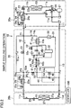
- the simple cooling operation will be described below with reference to FIG. 2 .
- the simple cooling operation is performed to cool the room using only the cold thermal energy obtained through a refrigeration cycle of the refrigerant circuit (11).
- the refrigerant circuit (11) performs a refrigeration cycle (simple cooling cycle) in which the outdoor heat exchanger (22) serves as a condenser and the indoor heat exchanger (27) serves as an evaporator.
- the thermal storage medium in the thermal storage circuit (31) does not circulate.
- the four-way switching valve (28) is set to the first state.
- the discharge end of the compressor (21) is connected to the gas end of the outdoor heat exchanger (22), and the suction end of the compressor (21) is connected to the gas refrigerant channel (13).
- the first open/close valve (51) is opened, and the second and third open/close valves (52, 53) are closed.
- the outdoor expansion valve (23) is fully opened, the degree of opening of the indoor expansion valve (26) is adjusted to a predetermined degree (a degree of opening which allows the refrigerant at the exit of the indoor heat exchanger (27) to have a target degree of superheat), and the thermal storage expansion valve (42) is fully closed.
- the degree of opening of the outdoor subcooling expansion valve (24c) is adjusted to a predetermined degree, and the thermal storage expansion valve (25c) is fully closed.
- the pressure regulating valve (45) is fully closed, and the channel open/close valve (46) is opened. Then, the compressor (21), the outdoor fan (22a), and the indoor fan (27a) are driven, while the circulation pump (33) is stopped.
- the setting and regulation described above are performed in response to the control by the controller (100). The same will be applied to the following description.
- the refrigerant discharged from the compressor (21) flows into the outdoor heat exchanger (22), and is condensed through heat dissipation into the outdoor air in the outdoor heat exchanger (22).
- the refrigerant that has flowed from the outdoor heat exchanger (22) passes through the outdoor expansion valve (23) which is fully opened, flows into the outdoor subcooling heat exchanger (24), and is cooled in the outdoor subcooling heat exchanger (24).
- the refrigerant that has flowed from the outdoor subcooling heat exchanger (24) sequentially passes through the opened first open/close valve (51) and the thermal storage subcooling heat exchanger (25) in the liquid refrigerant channel (12) to flow into the indoor expansion valve (26), and has its pressure reduced by the indoor expansion valve (26).
- the refrigerant that has passed through the indoor expansion valve (26) flows into the indoor heat exchanger (27), and absorbs heat from the indoor air in the indoor heat exchanger (27) to evaporate.
- the indoor air is cooled in this manner.
- the refrigerant that has flowed from the indoor heat exchanger (27) is sucked into the compressor (21) through the gas refrigerant channel (13), and is compressed again.
- the refrigerant may be prevented from accumulating in the refrigerant passage (43a) of the thermal storage heat exchanger (43).
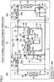
- the simple heating operation will be described below with reference to FIG. 3 .
- the simple heating operation is performed to heat the room using only the warm thermal energy obtained through a refrigeration cycle of the refrigerant circuit (11).
- the refrigerant circuit (11) performs a refrigeration cycle (simple heating cycle) in which the indoor heat exchanger (27) serves as a condenser and the outdoor heat exchanger (22) serves as an evaporator.
- the thermal storage medium in the thermal storage circuit (31) does not circulate.
- the four-way switching valve (28) is set to the second state.
- the discharge end of the compressor (21) is connected to the gas refrigerant channel (13), and the suction end of the compressor (21) is connected to the gas end of the outdoor heat exchanger (22).
- the first, second, and third open/close valves (51, 52, 53) are closed.
- the degree of opening of the outdoor expansion valve (23) is adjusted to a predetermined degree (a degree of opening which allows the refrigerant at the exit of the outdoor heat exchanger (22) to have a target degree of superheat).
- the degree of opening of the indoor expansion valve (26) is adjusted to a predetermined degree (a degree of opening which allows the refrigerant at the exit of the indoor heat exchanger (27) to have a target degree of subcooling), and the thermal storage expansion valve (42) is fully closed.
- the outdoor subcooling expansion valve (24c), and the thermal storage subcooling expansion valve (25c) are fully closed.
- the pressure regulating valve (45) is fully closed, and the channel open/close valve (46) is closed.
- the compressor (21), the outdoor fan (22a), and the indoor fan (27a) are driven, and the circulation pump (33) is stopped.
- the refrigerant discharged from the compressor (21) flows through the gas refrigerant channel (13) into the indoor heat exchanger (27), and is condensed through heat dissipation into the indoor air in the indoor heat exchanger (27).
- the indoor air is cooled in this manner.
- the refrigerant that has flowed from the indoor heat exchanger (27) sequentially passes through the indoor expansion valve (26), and the thermal storage subcooling heat exchanger (25), the third junction (P3), the first check valve (51a), and the first junction (PI) in the liquid refrigerant channel (12), flows through the outdoor subcooling heat exchanger (24), and has its pressure reduced by the outdoor expansion valve (23).
- the refrigerant that has passed through the outdoor expansion valve (23) flows into the outdoor heat exchanger (22), and absorbs heat from the outdoor air in the outdoor heat exchanger (22) to evaporate.
- the refrigerant that has flowed from the outdoor heat exchanger (22) is sucked into the compressor (21), and is compressed again.
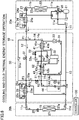
- the cold thermal energy storage operation will be described below with reference to FIG. 4 .
- the cold thermal energy storage operation is performed to store, in the thermal storage tank (32) of the thermal storage circuit (31), the cold thermal energy obtained through the refrigeration cycle of the refrigerant circuit (11).
- the refrigerant circuit (11) performs a refrigeration cycle (cold thermal energy storage cycle) in which the outdoor heat exchanger (22) serves as a condenser, the preheating heat exchanger (41) serves as a subcooler, and the thermal storage heat exchanger (43) serves as an evaporator.
- the thermal storage circuit (31) performs a circulation operation (of circulating the thermal storage medium).
- the four-way switching valve (28) is set to the first state.
- the discharge end of the compressor (21) is connected to the gas end of the outdoor heat exchanger (22), and the suction end of the compressor (21) is connected to the gas refrigerant channel (13).
- the first open/close valve (51) is opened, and the second and third open/close valves (52, 53) are closed.
- the outdoor expansion valve (23) is fully opened, the indoor expansion valve (26) is fully closed, and the degree of opening of the thermal storage expansion valve (42) is adjusted to a predetermined degree (a degree of opening which allows the refrigerant at the exit of the thermal storage heat exchanger to have a target evaporating temperature).
- the outdoor subcooling expansion valve (24c), and the thermal storage subcooling expansion valve (25c) are fully closed.
- the pressure regulating valve (45) is fully closed, and the channel open/close valve (46) is opened.
- the compressor (21) and the outdoor fan (22a) are driven, the indoor fan (27a) is stopped, and the circulation pump (33) is driven.
- the compressor (21) is actuated at a generally constant rotational speed.
- the refrigerant discharged from the compressor (21) flows into the outdoor heat exchanger (22), and is condensed through heat dissipation into the outdoor air in the outdoor heat exchanger (22).
- the refrigerant that has flowed from the outdoor heat exchanger (22) sequentially passes through the outdoor expansion valve (23) being fully opened and the outdoor subcooling heat exchanger (24), and flows into the liquid refrigerant channel (12).
- the refrigerant that has flowed into the liquid refrigerant channel (12) passes through the first junction (PI) and flows into the bypass channel (14).
- the refrigerant that has flowed into the bypass channel (14) flows into the refrigerant passage (41a) of the preheating heat exchanger (41), and is cooled through heat dissipation into the thermal storage medium flowing through the thermal storage medium passage (41b) while passing through the refrigerant passage (41a) of the preheating heat exchanger (41).
- the refrigerant that has flowed from the refrigerant passage (41a) of the preheating heat exchanger (41) has its pressure reduced by the thermal storage expansion valve (42), flows into the refrigerant passage (43a) of the thermal storage heat exchanger (43), and absorbs heat from the thermal storage medium flowing through the thermal storage medium passage (43b) to evaporate while passing through the refrigerant passage (43a) of the thermal storage heat exchanger (43).
- the refrigerant that has flowed from the refrigerant passage (43a) of the thermal storage heat exchanger (43) sequentially passes through the opened channel open/close valve (46) of the pressure regulating mechanism (44) and the gas refrigerant channel (13), and is sucked into the compressor (21) to be compressed again.
- the liquid refrigerant accumulates in the pipe (liquid pipe) of the bypass channel (14) between the first junction (P1) and the indoor expansion valve (26).
- the state of the refrigerant in this pipe is the same as that during the simple cooling operation. This may prevent the generation of a surplus refrigerant.
- the thermal storage medium that has flowed from the thermal storage tank (32) flows into the thermal storage medium passage (41b) of the preheating heat exchanger (41), and is heated by the refrigerant flowing through the refrigerant passage (41a) while passing through the thermal storage medium passage (41b) of the preheating heat exchanger (41).
- the thermal storage medium that has flowed from the thermal storage medium passage (41b) of the preheating heat exchanger (41) flows through the circulation pump (33) into the thermal storage medium passage (43b) of the thermal storage heat exchanger (43), and is cooled by the refrigerant flowing through the refrigerant passage (43a) while passing through the thermal storage medium passage (43b) of the thermal storage heat exchanger (43).
- the thermal storage medium that has flowed from the thermal storage medium passage (43b) of the thermal storage heat exchanger (43) flows into the thermal storage tank (32).
- the cold thermal energy is stored in the thermal storage tank (32) in this manner.
- the utilization cooling operation will be described below with reference to FIG. 5 .
- the utilization cooling operation is performed to cool the room using the cold thermal energy stored in the thermal storage tank (32) and the cold thermal energy obtained through the refrigeration cycle of the refrigerant circuit (11).
- the refrigerant circuit (11) performs a refrigeration cycle (utilization cooling cycle) in which the outdoor heat exchanger (22) serves as a condenser, the preheating heat exchanger (41) and the thermal storage heat exchanger (43) serve as subcoolers, and the indoor heat exchanger (27) serves as an evaporator.
- the thermal storage circuit (31) performs a circulation operation.
- the four-way switching valve (28) is set to the first state.
- the discharge end of the compressor (21) is connected to the gas end of the outdoor heat exchanger (22), and the suction end of the compressor (21) is connected to the gas refrigerant channel (13).
- the first open/close valve (51) is closed, and the second and third open/close valves (52, 53) are opened.
- the outdoor expansion valve (23) is fully opened, the degree of opening of the indoor expansion valve (26) is adjusted to a predetermined degree (a degree of opening which allows the refrigerant at the exit of the indoor heat exchanger to have a target degree of superheat), and the thermal storage expansion valve (42) is fully opened.
- the outdoor subcooling expansion valve (24c) is fully closed, and the degree of opening of the thermal storage subcooling expansion valve (25c) is adjusted to a predetermined degree.
- the pressure regulating valve (45) is fully closed, and the channel open/close valve (46) is closed.
- the compressor (21), the outdoor fan (22a), the indoor fan (27a), and the circulation pump (33) are all driven.
- the refrigerant discharged from the compressor (21) flows into the outdoor heat exchanger (22), and is condensed through heat dissipation into the outdoor air in the outdoor heat exchanger (22).
- the refrigerant that has flowed from the outdoor heat exchanger (22) sequentially passes through the outdoor expansion valve (23) being fully opened and the outdoor subcooling heat exchanger (24), and flows into the liquid refrigerant channel (12).
- the refrigerant that has flowed into the liquid refrigerant channel (12) passes through the first junction (PI) and flows into the bypass channel (14).
- the refrigerant that has flowed into the bypass channel (14) flows into the refrigerant passage (41a) of the preheating heat exchanger (41), and is cooled through heat dissipation into the thermal storage medium flowing through the thermal storage medium passage (41b) while passing through the refrigerant passage (41a) of the preheating heat exchanger (41).
- the refrigerant that has flowed from the refrigerant passage (43a) of the thermal storage heat exchanger (43) sequentially passes through the opened third open/close valve (53) and the third check valve (53a) to flow into the liquid refrigerant channel (12), sequentially passes through the third and second junctions (P3, P2) in the liquid refrigerant channel (12) to flow into the thermal storage subcooling heat exchanger (25), and is cooled in the thermal storage subcooling heat exchanger (25).
- the refrigerant that has passed through the thermal storage subcooling heat exchanger (25) has its pressure reduced by the indoor expansion valve (26), flows into the indoor heat exchanger (27), and absorbs heat from the indoor air in the indoor heat exchanger (27) to evaporate. The indoor air is cooled in this manner.
- the refrigerant that has flowed from the indoor heat exchanger (27) is sucked into the compressor (21) through the gas refrigerant channel (13), and is compressed again.
- the thermal storage medium that has flowed from the thermal storage tank (32) flows into the thermal storage medium passage (41b) of the preheating heat exchanger (41), and absorbs heat from the refrigerant flowing through the refrigerant passage (41a) while passing through the thermal storage medium passage (41b) of the preheating heat exchanger (41).
- the thermal storage medium that has flowed from the thermal storage medium passage (41b) of the preheating heat exchanger (41) flows through the circulation pump (33) into the thermal storage medium passage (43b) of the thermal storage heat exchanger (43), and absorbs heat from the refrigerant flowing through the refrigerant passage (43a) while passing through the thermal storage medium passage (43b) of the thermal storage heat exchanger (43).
- the thermal storage medium that has flowed from the thermal storage medium passage (43b) of the thermal storage heat exchanger (43) flows into the thermal storage tank (32). The cold thermal energy is given to the refrigerant from the thermal storage medium in this manner.
- the cooling and cold thermal energy storage operation will be described below with reference to FIG. 6 .
- the cooling and cold thermal energy storage operation is performed to cool the room using part of the cold thermal energy obtained through the refrigeration cycle of the refrigerant circuit (11), while storing the rest of the cold thermal energy in the thermal storage tank. That is, during the cooling and cold thermal energy storage operation, storing the cold thermal energy and cooling the room are simultaneously performed.
- the refrigerant circuit (11) performs a refrigeration cycle (cooling and cold thermal energy storage cycle) in which the outdoor heat exchanger (22) serves as a condenser, the preheating heat exchanger (41) serves as a subcooler, and the indoor heat exchanger (27) and the thermal storage heat exchanger (43) serve as evaporators.
- the thermal storage circuit (31) performs a circulation operation.
- the four-way switching valve (28) is set to the first state.
- the discharge end of the compressor (21) is connected to the gas end of the outdoor heat exchanger (22), and the suction end of the compressor (21) is connected to the gas refrigerant channel (13).
- the first open/close valve (51) is opened, and the second and third open/close valves (52, 53) are closed.
- the outdoor expansion valve (23) is fully opened, the degree of opening of the indoor expansion valve (26) is adjusted to a predetermined degree (a degree of opening which allows the refrigerant at the exit of the indoor heat exchanger to have a target degree of superheat), and the degree of opening of the thermal storage expansion valve (42) is adjusted to a predetermined degree (a degree of opening which allows the refrigerant at the exit of the thermal storage heat exchanger (43) to have a target degree of superheat).
- the outdoor subcooling expansion valve (24c) is fully closed, and the degree of opening of the thermal storage subcooling expansion valve (25c) is adjusted to a predetermined degree.
- the degree of opening of the pressure regulating valve (45) is adjusted to a predetermined degree, and the channel open/close valve (46) is closed.
- the compressor (21), the outdoor fan (22a), the indoor fan (27a), and the circulation pump (33) are all driven.
- the refrigerant discharged from the compressor (21) flows into the outdoor heat exchanger (22), and is condensed through heat dissipation into the outdoor air in the outdoor heat exchanger (22).
- the refrigerant that has flowed from the outdoor heat exchanger (22) sequentially passes through the fully opened outdoor expansion valve (23) and the outdoor subcooling heat exchanger (24), and flows into the liquid refrigerant channel (12).
- Part of the refrigerant that has flowed into the liquid refrigerant channel (12) and passed through the first junction (P1) flows into the opened first open/close valve (51), and the rest of the refrigerant flows into the bypass channel (14).
- the refrigerant that has passed through the first open/close valve (51) flows into, and is cooled in, the thermal storage subcooling heat exchanger (25).
- the refrigerant that has passed through the thermal storage subcooling heat exchanger (25) has its pressure reduced by the indoor expansion valve (26), flows into the indoor heat exchanger (27), and absorbs heat from the indoor air in the indoor heat exchanger (27) to evaporate.
- the indoor air is cooled in this manner.
- the refrigerant that has flowed from the indoor heat exchanger (27) flows into the gas refrigerant channel (13).
- the refrigerant that has flowed into the bypass channel (14) flows into the refrigerant passage (41a) of the preheating heat exchanger (41), and is cooled through heat dissipation into the thermal storage medium flowing through the thermal storage medium passage (41b) while passing through the refrigerant passage (41a) of the preheating heat exchanger (41).
- the refrigerant that has flowed from the refrigerant passage (41a) of the preheating heat exchanger (41) has its pressure reduced by the thermal storage expansion valve (42), flows into the refrigerant passage (43a) of the thermal storage heat exchanger (43), and absorbs heat from the thermal storage medium flowing through the thermal storage medium passage (43b) to evaporate while passing through the refrigerant passage (43a) of the thermal storage heat exchanger (43).
- the refrigerant that has flowed from the refrigerant passage (43a) of the thermal storage heat exchanger (43) has its pressure reduced by the pressure regulating valve (45) of the pressure regulating mechanism (44), and flows into the gas refrigerant channel (13).
- the refrigerant that has passed through the indoor heat exchanger (27) merges with the refrigerant that has passed through the pressure regulating valve (45) of the pressure regulating mechanism (44), and is sucked into the compressor (21) to be compressed again.
- the thermal storage medium that has flowed from the thermal storage tank (32) flows into the thermal storage medium passage (41b) of the preheating heat exchanger (41), and is heated by the refrigerant flowing through the refrigerant passage (41a) while passing through the thermal storage medium passage (41b) of the preheating heat exchanger (41).
- the thermal storage medium that has flowed from the thermal storage medium passage (41b) of the preheating heat exchanger (41) flows through the circulation pump (33) into the thermal storage medium passage (43b) of the thermal storage heat exchanger (43), and is cooled by the refrigerant flowing through the refrigerant passage (43a) while passing through the thermal storage medium passage (43b) of the thermal storage heat exchanger (43).
- the thermal storage medium that has flowed from the thermal storage medium passage (43b) of the thermal storage heat exchanger (43) flows into the thermal storage tank (32).
- the cold thermal energy is stored in the thermal storage tank (32) in this manner.
- the refrigerant flowing through the refrigerant passage (41a) of the preheating heat exchanger (41) heats the thermal storage medium flowing through the thermal storage medium passage (41b).
- the clathrate hydrates contained in the thermal storage medium flowed from the thermal storage tank (32) melt. This may prevent the circulation efficiency of the thermal storage medium from decreasing due to mass generation of the clathrate hydrates in the thermal storage circuit (31).
- the mass generation of the clathrate hydrates in the thermal storage medium, and the resulting clogging of the pipe forming the thermal storage circuit (31) may be prevented.
- the control (by the controller (100)) during the cooling and cold thermal energy storage operation shown in FIG. 6 will be described below.
- the controller (100) performs, in parallel, superheat degree control for the indoor unit, superheat degree control for the thermal storage unit, target low pressure control, and evaporating temperature control for the thermal storage unit.
- the temperature and degree of superheat to be described below can be detected based on the values detected by various sensors (not shown).
- the controller (100) regulates the degree of opening of the indoor expansion valve (26) such that the degree of superheat of the refrigerant at the exit of the indoor heat exchanger (27) (hereinafter will be referred to as the "degree of superheat of the indoor-unit refrigerant") is set to a predetermined target degree of superheat of the indoor-unit refrigerant.
- the controller (100) increases the degree of opening of the indoor expansion valve (26) if the degree of superheat of the indoor-unit refrigerant is higher than the associated target degree of superheat, and reduces the degree of opening of the indoor expansion valve (26) if the degree of superheat of the indoor-unit refrigerant is lower than the associated target degree of superheat.
- the controller (100) determines the target degree of superheat of the indoor-unit refrigerant such that it decreases with increase in difference between the temperature of the indoor air and a predetermined target cooling temperature (a difference obtained by subtracting the temperature of the indoor air from the target cooling temperature).
- the controller (100) regulates the degree of opening of the thermal storage expansion valve (42) such that the degree of superheat of the refrigerant at the exit of the thermal storage heat exchanger (43) (hereinafter will be referred to as the "degree of superheat of the thermal-storage-unit refrigerant") is set to a predetermined target degree of superheat of the thermal-storage-unit refrigerant.
- the controller (100) increases the degree of opening of the thermal storage expansion valve (42) if the degree of superheat of the thermal-storage-unit refrigerant is higher than the associated target degree of superheat, and decreases the degree of opening of the thermal storage expansion valve (42) if the degree of superheat of the thermal-storage-unit refrigerant is lower than the associated target degree of superheat.
- the degree of superheat of the thermal-storage-unit refrigerant can be calculated based on the values detected by the first and second refrigerant temperature sensors (61, 62).
- the controller (100) controls the rotational speed of the compressor (21) such that the low pressure in the refrigerant circuit (11) (the suction pressure of the compressor (21) in this example) reaches the predetermined target low pressure. Specifically, the controller (100) increases the rotational speed of the compressor (21) if the suction pressure of the compressor (21) is higher than the target low pressure, and reduces the rotational speed of the compressor (21) if the suction pressure of the compressor (21) is lower than the target low pressure. Note that the controller (100) determines the target low pressure such that the target low pressure decreases with increase in cooling load (i.e., a difference between the temperature of the indoor air and the target refrigerant temperature).
- the controller (100) adjusts the amount of pressure reduction by the pressure regulating mechanism (44) such that the evaporating temperature of the refrigerant in the thermal storage heat exchanger (43) (hereinafter will be referred to as the "evaporating temperature of the thermal-storage-unit refrigerant") does not fall below a predetermined lower limit evaporating temperature.
- the lower limit evaporating temperature is set to be a lower limit temperature in the range of the evaporating temperature of the refrigerant suitable for cooling the thermal storage medium in the thermal storage heat exchanger (43) (hereinafter will be referred to as the "suitable range of the evaporating temperature").
- the suitable range of the evaporating temperature can be determined based on the hydrate formation temperature in the thermal storage medium and the size (heat exchange area) of the thermal storage heat exchanger (43). For example, if a tetra-n-butyl ammonium bromide aqueous solution is adopted as the thermal storage medium, the suitable range of the evaporating temperature may be from about 4°C to 7°C. The lower limit evaporating temperature may be set to 4°C.
- the controller (100) regulates the degree of opening of the pressure regulating valve (45) of the pressure regulating mechanism (44) such that the evaporating temperature of the thermal-storage-unit refrigerant reaches a predetermined reference evaporating temperature. Specifically, the controller (100) reduces the degree of opening of the pressure regulating valve (45) if the evaporating temperature of the thermal-storage-unit refrigerant is lower than the reference evaporating temperature, and increases the degree of opening of the pressure regulating valve (45) if the evaporating temperature of the thermal-storage-unit refrigerant is higher than the reference evaporating temperature.
- the reference evaporating temperature is set to be a temperature obtained by adding a predetermined temperature (e.g., 1°C) to the lower limit evaporating temperature (i.e., a temperature higher than the lower limit evaporating temperature).
- a predetermined temperature e.g. 1°C
- the reference evaporating temperature is suitably set to be equal to or lower than the upper limit temperature in the suitable range of the evaporating temperature.
- the controller (100) is configured to perform the evaporating temperature control for the thermal storage unit using the value detected by the second refrigerant temperature sensor (62) (i.e., the temperature of the refrigerant at the inlet of the thermal storage heat exchanger (43)) as the evaporating temperature of the thermal-storage-unit refrigerant.
- the cooling load increases (i.e., if the temperature of the indoor air is higher than the target cooling temperature)
- the target low pressure decreases.
- the suction pressure of the compressor (21) becomes higher than the target low pressure
- the rotational speed of the compressor (21) increases to lower the suction pressure of the compressor (21).
- the evaporating pressure of the refrigerant in the indoor heat exchanger (27) decreases to lower the evaporating temperature of the refrigerant in the indoor heat exchanger (27).
- the cooling capacity i.e., capacity to cool the room
- the evaporating pressure of the refrigerant in the thermal storage heat exchanger (43) also decreases with decrease in the suction pressure of the compressor (21).
- the evaporating temperature of the refrigerant in the thermal storage heat exchanger (43) decreases to lower the value detected by the second refrigerant temperature sensor (62) (i.e., the temperature of the refrigerant at the inlet of the thermal storage heat exchanger (43)).
- the degree of opening of the pressure regulating valve (45) of the pressure regulating mechanism (44) decreases.
- the amount of pressure reduction by the pressure regulating valve (45) increases to raise the evaporating pressure of the refrigerant in the thermal storage heat exchanger (43).
- the evaporating temperature of the refrigerant in the thermal storage heat exchanger (43) increases.
- provision of the pressure regulating mechanism (44) allows the evaporating pressure of the refrigerant in the thermal storage heat exchanger (43) to be regulated such that the evaporating pressure becomes higher than the suction pressure of the compressor (21) during the cooling and cold thermal energy storage operation (i.e., when the refrigerant circuit (11) performs the cooling and cold thermal energy storage cycle).
- This may substantially prevent the evaporating pressure of the refrigerant in the thermal storage heat exchanger (43) from decreasing with the decrease in the suction pressure of the compressor (21), thereby substantially preventing the evaporating temperature of the refrigerant in the thermal storage heat exchanger (43) from decreasing too much.
- thermal storage heat exchanger (43) excessive cooling of the thermal storage medium in the thermal storage heat exchanger (43) may be prevented, which may substantially prevent the circulation efficiency of the thermal storage medium in the thermal storage circuit (31) from decreasing.
- the thermal storage medium in the thermal storage heat exchanger (43) is not cooled too much.
- mass generation of the clathrate hydrates i.e., solid components
- mass generation of the clathrate hydrates is less likely to occur, which may substantially prevent the circulation efficiency of the thermal storage medium from decreasing (specifically, the pipe forming the thermal storage circuit (31) from being clogged with the clathrate hydrates).
- the excessive cooling of the thermal storage medium in the thermal storage heat exchanger (43) may be prevented. This may substantially prevent the circulation efficiency of the thermal storage medium in the thermal storage circuit (31) from decreasing, while ensuring the cooling capacity (i.e., capacity to cool the room) of the indoor heat exchanger during the cooling and cold thermal energy storage operation.
- the amount of pressure reduction by the pressure regulating mechanism (44) (specifically, the degree of opening of the pressure regulating valve (45)) is adjusted such that the evaporating temperature of the refrigerant in the thermal storage heat exchanger (43) does not fall below the lower limit evaporating temperature.
- the evaporating temperature of the refrigerant in the thermal storage heat exchanger (43) may suitably be determined. Since the thermal storage medium can suitably be cooled in the thermal storage heating exchanger (43), the cold thermal energy may suitably be stored during the cooling and cold thermal energy storage operation.
- the pressure regulating mechanism (44) is comprised of the pressure regulating valve (45)
- the amount of pressure reduction by the pressure regulating mechanism (44) may be adjusted by regulating the degree of opening of the pressure regulating valve (45).
- the evaporating pressure of the refrigerant in the thermal storage heat exchanger (43) may be regulated such that the evaporating pressure is higher than the suction pressure of the compressor (21), which may prevent the excessive cooling of the thermal storage medium in the thermal storage heat exchanger (43).
- the pressure regulating mechanism (44) is comprised of the pressure regulating valve (45) and the channel open/close valve (46), the channel open/close valve (46) may be opened, while the pressure regulating valve (45) is fully closed.
- the refrigerant is allowed to flow between the thermal storage heat exchanger (43) and the gas refrigerant channel (13) via the channel open/close valve (46).
- a pressure loss in the channel open/close valve (46) is smaller than a pressure loss in the pressure regulating valve (45).
- the pressure loss in the pressure regulating mechanism (44) may be reduced as compared with the case where the refrigerant is allowed to flow between the thermal storage heat exchanger (43) and the gas refrigerant channel (13) via the pressure regulating valve (45).
- the pressure loss in the pressure regulating mechanism (44) may be reduced, which allows the other operations to be suitably performed.
- the thermal storage medium may be other thermal storage materials than the tetra-n-butyl ammonium bromide aqueous solution.
- the concentration of the thermal storage medium is not necessarily 40%.
- the thermal storage air conditioner described above is useful as an air conditioner which is able to store cold thermal energy by using the thermal storage effect of a thermal storage medium.
Landscapes
- Engineering & Computer Science (AREA)
- Mechanical Engineering (AREA)
- General Engineering & Computer Science (AREA)
- Physics & Mathematics (AREA)
- Thermal Sciences (AREA)
- Chemical & Material Sciences (AREA)
- Combustion & Propulsion (AREA)
- Life Sciences & Earth Sciences (AREA)
- Sustainable Development (AREA)
- Air Conditioning Control Device (AREA)
- Compression-Type Refrigeration Machines With Reversible Cycles (AREA)
Abstract
Description
- The present disclosure relates to a thermal storage air conditioner.
- A thermal storage air conditioner which cools the air in a room using a thermal storage medium as a cold thermal energy source has been known as disclosed by
Patent Document 1. According toPatent Document 1, a thermal storage heat exchanger having a channel through which a refrigerant flows is arranged in a thermal storage tank storing a thermal storage medium. The refrigerant cools the thermal storage medium. A thermal storage material in which clathrate hydrates are generated if cooled (e.g., a tetra-n-butyl ammonium bromide aqueous solution) is adopted as the thermal storage medium. The thermal storage air conditioner ofPatent Document 1 performs a cooling and cold thermal energy storage operation to cool the room while storing cold thermal energy. - Patent Document 1: Japanese Unexamined Patent Publication No.
2007-17089 - Regarding the thermal storage air conditioner disclosed by
Patent Document 1, it may be possible to arrange the thermal storage heat exchanger outside the thermal storage tank (thermal storage vessel) to form a thermal storage circuit through which the thermal storage medium circulates between the thermal storage heat exchanger and the thermal storage tank. If a cooling and cold thermal energy storage operation is performed in this configuration, the thermal storage medium that has flowed from the thermal storage tank into the thermal storage heat exchanger gives heat to the refrigerant flowing through the thermal storage heat exchanger while passing through the thermal storage heating exchanger, and is cooled. - Further, in the above-described configuration, the suction pressure of a compressor may be reduced to lower the evaporating pressure of the refrigerant in an indoor heat exchanger to ensure the cooling capacity of the indoor heat exchanger (i.e., capacity to cool the air in the room) during the cooling and cold thermal energy storage operation. For example, if there is a large pressure loss between a gas end of the indoor heat exchanger and a suction end of the compressor (more specifically, if the gas end of the indoor heat exchanger and the suction end of the compressor are connected via a long pipe, or there is a large difference in height between the gas end of the indoor heat exchanger and the suction end of the compressor), the suction pressure of the compressor is set to be low such that the evaporating pressure of the refrigerant in the indoor heat exchanger is set to a certain level required for ensuring the cooling capacity. Further, if a cooling load in the room increases to decrease the cooling capacity to an insufficient level, the suction pressure of the compressor is lowered to reduce the evaporating pressure of the refrigerant in the indoor heat exchanger.
- However, if the suction pressure of the compressor is lowered to reduce the evaporating pressure of the refrigerant in the indoor heat exchanger, the evaporating pressure of the refrigerant in the thermal storage heat exchanger also decreases with the decrease in the suction pressure of the compressor, thereby lowering the evaporating temperature of the refrigerant. Thus, the thermal storage medium in the thermal storage heat exchanger may possibly be cooled too much to generate a large amount of clathrate hydrates (solid component). As a result, the circulation efficiency of the thermal storage medium in the thermal storage circuit may possibly decrease.
- In view of the foregoing background, it is therefore an object of the present disclosure to provide a thermal storage air conditioner which may substantially prevent the decrease in circulation efficiency of the thermal storage medium while ensuring the cooling capacity during the cooling and cold thermal energy storage operation.
- A first aspect of the present disclosure is directed to a thermal storage air conditioner including: a refrigerant circuit (11) including a compressor (21), an outdoor heat exchanger (22), an indoor heat exchanger (27), a liquid refrigerant channel (12) connecting a liquid end of the outdoor heat exchanger (22) and a liquid end of the indoor heat exchanger (27), a gas refrigerant channel (13) connected to a gas end of the indoor heat exchanger (27), and a bypass channel (14) having one end connected to the liquid refrigerant channel (12) and the other end connected to the gas refrigerant channel (13); a thermal storage circuit (31) which allows a thermal storage medium, which would generate a solid component if cooled, to flow therein; a thermal storage heat exchanger (43) which is connected to the bypass channel (14) and the thermal storage circuit (31), and allows a refrigerant flowing through the bypass channel (14) and the thermal storage medium flowing through the thermal storage circuit (31) to exchange heat; and a pressure regulating mechanism (44) provided in the bypass channel (14) between the thermal storage heat exchanger (43) and the gas refrigerant channel (13), wherein the refrigerant circuit (11) performs a cooling and cold thermal energy storage cycle in which a discharge end of the compressor (21) is connected to a gas end of the outdoor heat exchanger (22), a suction end of the compressor (21) is connected to the gas refrigerant channel (13), the outdoor heat exchanger (22) serves as a condenser, and the indoor heat exchanger (27) and the thermal storage heat exchanger (43) serve as evaporators, and the pressure regulating mechanism (44) is configured to regulate a pressure of the refrigerant flowing between the thermal storage heat exchanger (43) and the gas refrigerant channel (13).
- According to the first aspect, provision of the pressure regulating mechanism (44) allows the evaporating pressure of the refrigerant in the thermal storage heat exchanger (43) to be regulated such that the evaporating pressure becomes higher than the suction pressure of the compressor (21) during the cooling and cold thermal energy storage operation (i.e., when the refrigerant circuit (11) performs the cooling and cold thermal energy storage cycle). This may substantially prevent the decrease in the evaporating pressure of the refrigerant in the thermal storage heat exchanger (43) with the decrease in the suction pressure of the compressor (21), thereby substantially preventing the evaporating temperature of the refrigerant in the thermal storage heat exchanger (43) from decreasing too much. Thus, the excessive cooling of the thermal storage medium in the thermal storage heat exchanger (43) may be prevented.
- A second aspect of the present disclosure is an embodiment of the first aspect described above. According to the second aspect, the thermal storage air conditioner further includes an operation control section (100) which instructs the refrigerant circuit (11) to perform the cooling and cold thermal energy storage cycle, and adjusts the amount of pressure reduction by the pressure regulating mechanism (44) such that an evaporating temperature of the refrigerant in the thermal storage heat exchanger (43) does not fall below a predetermined lower limit evaporating temperature.
- According to the second aspect, the evaporating pressure of the refrigerant in the thermal storage heat exchanger (43) may suitably be determined. Thus, the thermal storage medium can suitably be cooled in the thermal storage heating exchanger (43).
- A third aspect of the present disclosure is an embodiment of the first or second aspect described above. According to the third aspect, the bypass channel (14) includes a first channel portion (14d) which connects the thermal storage heat exchanger (43) and the gas refrigerant channel (13), and the pressure regulating mechanism (44) includes a pressure regulating valve (45) which is provided in the first channel portion (14d) and has an adjustable degree of opening.
- According to the third aspect, the amount of pressure reduction by the pressure regulating mechanism (44) may be adjusted by regulating the degree of opening of the pressure regulating valve (45). As a result, the evaporating pressure of the refrigerant in the thermal storage heat exchanger (43) may be regulated such that the evaporating pressure is higher than the suction pressure of the compressor (21), which may prevent the excessive cooling of the thermal storage medium in the thermal storage heat exchanger (43).
- A fourth aspect of the present disclosure is an embodiment of the third aspect described above. According to the fourth aspect, the bypass channel (14) further includes a second channel portion (14e) which is provided in parallel with the first channel portion (14d), and connects the thermal storage heat exchanger (43) and the gas refrigerant channel (13), and the pressure regulating mechanism (44) further includes an open/close valve (46) which is provided in the second channel portion (14e) and configured to be switchable between an open state and a closed state.
- According to the fourth aspect, the open/close valve (46) may be opened, while the pressure regulating valve (45) may be fully closed. Thus, the refrigerant is allowed to flow between the thermal storage heat exchanger (43) and the gas refrigerant channel (13) via the open/close valve (46). A pressure loss in the open/close valve (46) is smaller than a pressure loss in the pressure regulating valve (45). Thus, the pressure loss in the pressure regulating mechanism (44) may be reduced as compared with the case where the refrigerant is allowed to flow between the thermal storage heat exchanger (43) and the gas refrigerant channel (13) via the pressure regulating valve (45). As a result, during other operations than the cooling and cold thermal energy storage operation, the pressure loss in the pressure regulating mechanism (44) may be reduced.
- According to the first and third aspects, the excessive cooling of the thermal storage medium in the thermal storage heat exchanger (43) may be prevented. This may substantially prevent the circulation efficiency of the thermal storage medium in the thermal storage circuit (31) from decreasing, while ensuring the cooling capacity (i.e., capacity to cool the room) of the indoor heat exchanger during the cooling and cold thermal energy storage operation.
- According to the second aspect, the thermal storage medium can suitably be cooled in the thermal storage heating exchanger (43), and thus, the cold thermal energy may suitably be stored during the cooling and cold thermal energy storage operation.
- According to the fourth aspect, during other operations than the cooling and cold thermal energy storage operation, the pressure loss in the pressure regulating mechanism (44) may be reduced, which allows the other operations to be suitably performed.
-
- [
FIG. 1] FIG. 1 illustrates a configuration of a thermal storage air conditioner. - [
FIG. 2] FIG. 2 shows the flow of a refrigerant during a simple cooling operation. - [
FIG. 3] FIG. 3 shows the flow of a refrigerant during a simple heating operation. - [
FIG. 4] FIG. 4 shows the flow of a refrigerant and the flow of a thermal storage medium during a cold thermal energy storage operation. - [
FIG. 5] FIG. 5 shows the flow of a refrigerant and the flow of a thermal storage medium during a utilization cooling operation. - [
FIG. 6] FIG. 6 shows the flow of a refrigerant and the flow of a thermal storage medium during a cooling and cold thermal energy storage operation. - Embodiments of the present disclosure will now be described in detail with reference to the drawings. Note that like reference characters designate identical or corresponding components in the drawings, and description of components designated by like reference characters will not be repeated.
-
FIG. 1 illustrates an exemplary configuration of a thermal storage air conditioner (10) according to an embodiment. The thermal storage air conditioner (10) is comprised of an outdoor unit (20a), an indoor unit (20b), and a thermal storage unit (30), and includes a refrigerant circuit (11), a thermal storage circuit (31), a preheating heat exchanger (41), a thermal storage expansion valve (42), a thermal storage heat exchanger (43), a pressure regulating mechanism (44), and a controller (100). - The refrigerant circuit (11) is filled with a refrigerant. The refrigerant circulates in the refrigerant circuit (11) so that a refrigeration cycle is performed. The refrigerant circuit (11) includes a compressor (21), an outdoor heat exchanger (22), an outdoor expansion valve (23), an outdoor subcooling heat exchanger (24), a thermal storage subcooling heat exchanger (25), an indoor expansion valve (26), an indoor heat exchanger (27), and a four-way switching valve (28). The refrigerant circuit (11) further includes a liquid refrigerant channel (12), a gas refrigerant channel (13), a bypass channel (14), and a branch channel (15).
- The outdoor unit (20a) is placed outside the room. The outdoor unit (20a) includes the compressor (21), the outdoor heat exchanger (22), the outdoor expansion valve (23), the outdoor subcooling heat exchanger (24), and the four-way switching valve (28). The outdoor unit (20a) further includes an outdoor fan (22a) which transfers the air to the outdoor heat exchanger (22).
- The indoor unit (20b) is placed inside the room. The indoor unit (20b) includes the indoor expansion valve (26) and the indoor heat exchanger (27). The indoor unit (20b) further includes an indoor fan (27a) which transfers the air to the indoor heat exchanger (27).
- The thermal storage unit (30) is connected between the outdoor and indoor units (20a, 20b) to be adjacent to the outdoor unit (20a). The thermal storage unit (30) includes the thermal storage subcooling heat exchanger (25), the thermal storage circuit (31), the preheating heat exchanger (41), the thermal storage expansion valve (42), the thermal storage heat exchanger (43), and the pressure regulating mechanism (44).
- The compressor (21) has a discharge end connected to a first port of the four-way switching valve (28), and a suction end connected to a second port of the four-way switching valve (28). The compressor (21) compresses a refrigerant sucked therein, and discharges the refrigerant thus compressed. The compressor (21) has a variable capacity (rotational speed). For example, the compressor (21) is a variable capacity compressor, the rotational speed (i.e., the operating frequency) of which is varied by an inverter circuit (not shown).
- The outdoor heat exchanger (22) has a gas end connected to a third port of the four-way switching valve (28) via a first refrigerant pipe (11a), and a liquid end connected to one end of the refrigerant channel (12) via a second refrigerant pipe (11b). The outdoor expansion valve (23) and the outdoor subcooling heat exchanger (24) are sequentially arranged in the second refrigerant pipe (11b) in the direction from a liquid end of the outdoor heat exchanger (22) to the one end of the liquid refrigerant channel (12). Specifically, the liquid end of the outdoor heat exchanger (22) is connected to the liquid refrigerant channel (12) via the outdoor expansion valve (23) and the outdoor subcooling heat exchanger (24) arranged in this order. The outdoor heat exchanger (22) allows the refrigerant and the outdoor air transferred by the outdoor fan (22a) to exchange heat. The outdoor heat exchanger (22) is, for example, a cross-fm-and-tube heat exchanger.
- The outdoor expansion valve (23) has an adjustable degree of opening, adjustment of which regulates the pressure and flow rate of the refrigerant. The outdoor expansion valve (23) is configured, for example, as an electronic expansion valve (motor-operated valve).
- The outdoor subcooling heat exchanger (24) includes a high-pressure passage (24a) and a low-pressure passage (24b). The high-pressure passage (24a) is inserted in (connected to) the second refrigerant pipe (11b) in series. The low-pressure passage (24b) is inserted in an auxiliary pipe (24d) in series. The auxiliary pipe (24d) has one end connected to the second refrigerant pipe (11b) between the outdoor expansion valve (23) and the outdoor subcooling heat exchanger (24), and the other end connected to the suction end of the compressor (21). The outdoor subcooling heat exchanger (24) is configured to allow the refrigerant flowing through the high-pressure passage (24a) and the refrigerant flowing through the low-pressure passage (24b) to exchange heat so as to subcool the refrigerant flowing through the high-pressure passage (24a). The auxiliary pipe (24d) is provided with an outdoor subcooling expansion valve (24c) which regulates the flow rate of the refrigerant flowing through the low-pressure passage (24b).
- The thermal storage subcooling heat exchanger (25) is provided in the liquid refrigerant channel (12). The thermal storage subcooling heat exchanger (25) is provided adjacent to the other end of the liquid refrigerant channel (12). The thermal storage subcooling heat exchanger (25) has a high-pressure passage (25a) and a low-pressure passage (25b). The high-pressure passage (25a) is inserted in the liquid refrigerant channel (12) in series. The low-pressure passage (25b) is inserted in an auxiliary pipe (25d) in series. The auxiliary pipe (25d) has one end connected to some midpoint of the liquid refrigerant channel (12) between the one end of the liquid refrigerant channel (12) and the thermal storage subcooling heat exchanger (25), and the other end connected to the gas refrigerant channel (13). The thermal storage subcooling heat exchanger (25) is configured to allow the refrigerant flowing through the high-pressure passage (25a) and the refrigerant flowing through the low-pressure passage (25b) to exchange heat so as to subcool the refrigerant flowing through the high-pressure passage (25a). The auxiliary pipe (25d) is provided with a thermal storage subcooling expansion valve (25c) which regulates the flow rate of the refrigerant flowing through the low-pressure passage (25b).
- The indoor expansion valve (26) is provided for a third refrigerant pipe (11c) connecting the other end of the liquid refrigerant channel (12) and the liquid end of the indoor heat exchanger (27). The indoor expansion valve (26) has an adjustable degree of opening, adjustment of which regulates the pressure and flow rate of the refrigerant. The indoor expansion valve (26) is configured, for example, as an electronic expansion valve (motor-operated valve).
- The indoor heat exchanger (27) has a liquid end connected the other end of the liquid refrigerant channel (12) via the third refrigerant pipe (11c), and has a gas end connected to one end of the gas refrigerant channel (13) via a fourth refrigerant pipe (11d). Specifically, the liquid end of the indoor heat exchanger (27) is connected to the liquid refrigerant channel (12) via the indoor expansion valve (26). The indoor heat exchanger (27) allows the refrigerant and indoor air transferred by the indoor fan (27a) to exchange heat. The indoor air that has exchanged heat in the indoor heat exchanger (27) is fed into the room again. The indoor heat exchanger (27) is, for example, a cross-fin-and-tube heat exchanger.
- The four-way switching valve (28) switches the connection state of the first to fourth ports between a first state (the state indicated by the solid curves in
FIG. 1 ) and a second state (the state indicated by broken curves inFIG. 1 ) according to the operational mode of the thermal storage air conditioner (10). The fourth port of the four-way switching valve (28) is connected to the other end of the gas refrigerant channel (13) via a fifth refrigerant pipe (11e). - The bypass channel (14) has one end connected to the liquid refrigerant channel (12), and the other end connected to the gas refrigerant channel (13). The preheating heat exchanger (41), the thermal storage expansion valve (42), the thermal storage heat exchanger (43), and the pressure regulating mechanism (44) are sequentially arranged on the bypass channel (14) in the direction from the one end to other of the bypass channel (14), i.e., from the liquid refrigerant channel (12) to the gas refrigerant channel (13).
- A junction (a first junction (P1)) of the bypass channel (14) and the liquid refrigerant channel (12) is closer to the one end of the liquid refrigerant channel (12), i.e., the second refrigerant pipe (11b), than a junction (a second junction (P2)) of the auxiliary pipe (25d) of the thermal storage subcooling heat exchanger (25) and the liquid refrigerant channel (12) is. In this example, the bypass channel (14) includes a first primary pipe (14a), a second primary pipe (14b), a third primary pipe (14c), a first branch pipe (14d), and a second branch pipe (14e). The first primary pipe (14a) connects the preheating heat exchanger (41) to some midpoint of the liquid refrigerant channel (12). The second primary pipe (14b) connects the preheating heat exchanger (14) and the thermal storage heat exchanger (43). The third primary pipe (14c) has one end connected to the thermal storage heat exchanger (43). The first branch pipe (14d) connects the other end of the third primary pipe (14c) and the gas refrigerant channel (13). The second branch pipe (14e) is arranged in parallel with the first branch pipe (14d), and connects the third primary pipe (14c) and the gas refrigerant channel (13). Specifically, the first branch pipe (14d) constitutes a pipe (first channel portion) connecting the thermal storage heat exchanger (43) and the gas refrigerant channel (13). The second branch pipe (14e) constitutes a pipe (second channel portion) which is arranged in parallel with the first branch pipe (14d) and connects the thermal storage heat exchanger (43) and the gas refrigerant channel (13).
- The branch channel (15) has one end connected to some midpoint of the bypass channel (14) between the thermal storage heat exchanger (43) and the pressure regulating mechanism (44), and the other end connected to some midpoint of the liquid refrigerant channel (12) between the first and second junctions (PI, P2). Specifically, a junction (a third junction (P3)) of the branch channel (15) and the liquid refrigerant channel (12) is located between the first and second junctions (P1, P2) on the liquid refrigerant channel (12).
- The refrigerant circuit (11) further includes a first open/close valve (51), a second open/close valve (52), a third open/close valve (53), a first check valve (51a), a second check valve (52a), and a third check valve (53a). For example, the first, second and third open/close valves (51, 52, 53) are configured as solenoid valves.
- The first open/close valve (51) is provided between the first and second junctions (P1, P2) on the liquid refrigerant channel (12). The first check valve (51a) is connected in parallel with the first open/close valve (51). Further, the first check valve (51a) is configured to allow the refrigerant to flow from the thermal storage subcooling heat exchanger (25) to the outdoor subcooling heat exchanger (24) during a simple heating operation to be described later.
- The second open/close valve (52) is connected in parallel with the thermal storage expansion valve (42). The second check valve (52a) is connected to the second open/close valve (52) in series, and is parallel to the thermal storage expansion valve (42). The second check valve (52a) allows the refrigerant to flow only from the preheating heat exchanger (41) toward the thermal storage heat exchanger (43).
- The third open/close valve (53) is provided in the branch channel (15). The third check valve (53a) is provided for the branch channel (15), and allows the refrigerant to flow only from the bypass channel (14) toward the liquid refrigerant channel (12).
- The preheating heat exchanger (41) is connected to the bypass channel (14) of the refrigerant circuit (11) and the thermal storage circuit (31), and allows the refrigerant flowing through the bypass channel (14) to exchange heat with the thermal storage medium flowing through the thermal storage circuit (31). Specifically, the preheating heat exchanger (41) includes a refrigerant passage (41a) and a thermal storage medium passage (41b). The refrigerant passage (41a) is inserted in the bypass channel (14) in series. In this example, the refrigerant passage (41a) is connected to the bypass channel (14) between the first and second primary pipes (14a, 14b). The thermal storage medium passage (41b) is inserted in the thermal storage circuit (31) in series. The preheating heat exchanger (41) allows the refrigerant flowing through the refrigerant passage (41a) and the thermal storage medium flowing through the thermal storage medium passage (41b) to exchange heat.
- The thermal storage expansion valve (42) is provided on the bypass channel (14) between the preheating heat exchanger (41) and the thermal storage heat exchanger (43). In this example, the thermal storage expansion valve (42) is provided in the second primary pipe (14b) of the bypass channel (14). The thermal storage expansion valve (42) has an adjustable degree of opening, adjustment of which regulates the pressure and flow rate of the refrigerant. The thermal storage expansion valve (42) is configured, for example, as an electronic expansion valve (motor-operated valve).
- A pressure release valve (42a) is connected in parallel to the thermal storage expansion valve (42). The pressure release valve (42a) releases the pressure of the thermal storage heat exchanger (43) side if it exceeds an allowable value while the thermal storage air conditioner (10) is being suspended, for example.
- The thermal storage heat exchanger (43) is connected to the bypass channel (14) of the refrigerant circuit (11) and the thermal storage circuit (31), and allows the refrigerant flowing through the bypass channel (14) to exchange heat with the thermal storage medium flowing through the thermal storage circuit (31). Specifically, the thermal storage heat exchanger (43) includes a refrigerant passage (43a) and a thermal storage medium passage (43b). The refrigerant passage (43a) is inserted in the bypass channel (14) in series. In this example, the refrigerant passage (43a) is connected to the bypass channel (14) between the second and third primary pipes (14b, 14c). The thermal storage medium passage (43b) is inserted in the thermal storage circuit (31) in series. The thermal storage heat exchanger (43) allows the refrigerant flowing through the refrigerant passage (43a) and the thermal storage medium flowing through the thermal storage medium passage (43b) to exchange heat.
- The pressure regulating mechanism (44) is provided in the bypass channel (14) between the thermal storage heat exchanger (43) and the gas refrigerant channel (13). The pressure regulating mechanism (44) is configured to regulate the pressure of the refrigerant flowing between the thermal storage heat exchanger (43) and the gas refrigerant channel (13).
- In this example, the pressure regulating mechanism (44) includes a pressure regulating valve (45) and a channel open/close valve (46). The pressure regulating valve (45) is provided in the first branch pipe (14d) of the bypass channel (14). The degree of opening of the pressure regulating valve (45) is adjustable. The pressure regulating valve (45) is configured, for example, as a motor-operated valve. The channel open/close valve (46) is provided in the second branch pipe (14e) of the bypass channel (14). The channel open/close valve (46) is configured to be switchable between an open state and a closed state. The channel open/close valve (46) is configured, for example, as a solenoid valve.
- The thermal storage circuit (31) is filled with a thermal storage medium. The thermal storage circuit (31) performs a circulation operation by circulating the thermal storage medium. The thermal storage circuit (31) includes a thermal storage tank (32) and a circulation pump (33).
- The thermal storage tank (32) is a hollow vessel in which the thermal storage medium is stored. For example, the thermal storage tank (32) has a cylindrical shape with both ends being closed, and is arranged such that its axial direction extends vertically. The thermal storage tank (32) has an outlet and an inlet. For example, the outlet is located above the inlet.
- The circulation pump (33) circulates the thermal storage medium among the thermal storage tank (32), the preheating heat exchanger (41) and the thermal storage heat exchanger (43) in the thermal storage circuit (31). The thermal storage medium circulates as described below. Specifically, the thermal storage medium that has flowed out of the thermal storage tank (32) passes through the thermal storage medium passage (41b) of the preheating heat exchanger (41) and the circulation pump (33), and then flows through the thermal storage medium passage (43b) of the thermal storage heat exchanger (43) into the thermal storage tank (32). The controller (100) controls the on/off operations of the circulation pump (33) and the flow rate of the thermal storage medium transferred by the circulation pump (33).
- The thermal storage medium will now be described. The thermal storage medium can be a medium in which a solid component is generated when cooled (more specifically, a medium in which a solid component is generated when cooled to a temperature higher than 0°C and lower than 20°C). The solid component is a component which has experienced phase transition (i.e., latent heat change) from a liquid phase at its melting point, and generating heat. Examples of the solid component may include clathrate hydrates.
- An exemplary example will be described below. In this example, a thermal storage material in which clathrate hydrates are generated when cooled (i.e., a thermal storage material having flowability) is adopted as the thermal storage medium. Examples of such a thermal storage medium may include: a tetra-n-butyl ammonium bromide aqueous solution containing tetra-n-butyl ammonium bromide (TBAB); a trimethylolethane (TME) aqueous solution; and paraffin-based slurry. For example, the tetra-n-butyl ammonium bromide aqueous solution maintains the aqueous solution state even if it is stably cooled and turns into a subcooled state in which the temperature of the aqueous solution is lower than a hydrate formation temperature. However, once some trigger is given in this subcooled state, the subcooled solution transitions to a solution containing clathrate hydrates (i.e., transitions to slurry). That is, the subcooled state of the tetra-n-butyl ammonium bromide aqueous solution is changed to the state of slurry with relatively high viscosity due to the generation of clathrate hydrates (hydrate crystals) made of tetra-n-butyl ammonium bromide and water molecules. The subcooled state as used herein refers to a state in which clathrate hydrates are not generated and the state of solution is maintained even if the thermal storage medium reaches a temperature lower than or equal to the hydrate formation temperature. On the other hand, the clathrate hydrates melt if the temperature of the tetra-n-butyl ammonium bromide aqueous solution becomes higher, by heating, than the hydrate formation temperature. Then, the tetra-n-butyl ammonium bromide aqueous solution in the state of slurry turns to liquid (i.e., a solution) with relatively high flowability.
- In the present embodiment, a tetra-n-butyl ammonium bromide aqueous solution containing tetra-n-butyl ammonium bromide is adopted as the thermal storage medium. In particular, it is recommended that the thermal storage medium has a concentration close to a congruent concentration. The congruent concentration refers to a concentration of an aqueous solution which does not change before and after the generation of the clathrate hydrates. In the present embodiment, the congruent concentration is set to about 40%. In this case, the hydrate formation temperature of the tetra-n-butyl ammonium bromide aqueous solution is about 12°C.
- Note that the hydrate formation temperature of the tetra-n-butyl ammonium bromide aqueous solution varies depending on the concentration of the thermal storage medium. For example, if the thermal storage medium has a concentration of about 20%, the hydrate formation temperature is about 8.5°C.
- The thermal storage air conditioner (10) is provided with various sensors, such as a first refrigerant temperature sensor (61) and a second refrigerant temperature sensor (62).
- The first refrigerant temperature sensor (61) detects the temperature of the refrigerant (first refrigerant temperature) adjacent to one end side (the gas refrigerant channel (13) side) of the thermal storage heat exchanger (43). In this example, the first refrigerant temperature sensor (61) is arranged adjacent to one end of the refrigerant passage (43a) of the thermal storage heat exchanger (43), and detects the temperature of the refrigerant at this position as a first refrigerant temperature.
- The second refrigerant temperature sensor (62) detects the temperature of the refrigerant (second refrigerant temperature) adjacent to the other end side (the liquid refrigerant channel (12) side) of the thermal storage heat exchanger (43). In this example, the second refrigerant temperature sensor (62) is arranged adjacent to the other end of the refrigerant passage (43a) of the thermal storage heat exchanger (43), and detects the temperature of the refrigerant at this position as a second refrigerant temperature.
- The controller (100) controls the components of the thermal storage air conditioner (10) to control the operation of the thermal storage air conditioner (10) based on the values detected by various sensors. This thermal storage air conditioner (10) performs a simple cooling operation, a simple heating operation, a cold thermal energy storage operation, a utilization cooling operation, and a cooling and cold thermal energy storage operation.
- The simple cooling operation will be described below with reference to
FIG. 2 . The simple cooling operation is performed to cool the room using only the cold thermal energy obtained through a refrigeration cycle of the refrigerant circuit (11). - The refrigerant circuit (11) performs a refrigeration cycle (simple cooling cycle) in which the outdoor heat exchanger (22) serves as a condenser and the indoor heat exchanger (27) serves as an evaporator. The thermal storage medium in the thermal storage circuit (31) does not circulate.
- Specifically, the four-way switching valve (28) is set to the first state. As a result, the discharge end of the compressor (21) is connected to the gas end of the outdoor heat exchanger (22), and the suction end of the compressor (21) is connected to the gas refrigerant channel (13). Further, the first open/close valve (51) is opened, and the second and third open/close valves (52, 53) are closed. The outdoor expansion valve (23) is fully opened, the degree of opening of the indoor expansion valve (26) is adjusted to a predetermined degree (a degree of opening which allows the refrigerant at the exit of the indoor heat exchanger (27) to have a target degree of superheat), and the thermal storage expansion valve (42) is fully closed. The degree of opening of the outdoor subcooling expansion valve (24c) is adjusted to a predetermined degree, and the thermal storage expansion valve (25c) is fully closed. The pressure regulating valve (45) is fully closed, and the channel open/close valve (46) is opened. Then, the compressor (21), the outdoor fan (22a), and the indoor fan (27a) are driven, while the circulation pump (33) is stopped. The setting and regulation described above are performed in response to the control by the controller (100). The same will be applied to the following description.
- The refrigerant discharged from the compressor (21) flows into the outdoor heat exchanger (22), and is condensed through heat dissipation into the outdoor air in the outdoor heat exchanger (22). The refrigerant that has flowed from the outdoor heat exchanger (22) passes through the outdoor expansion valve (23) which is fully opened, flows into the outdoor subcooling heat exchanger (24), and is cooled in the outdoor subcooling heat exchanger (24). The refrigerant that has flowed from the outdoor subcooling heat exchanger (24) sequentially passes through the opened first open/close valve (51) and the thermal storage subcooling heat exchanger (25) in the liquid refrigerant channel (12) to flow into the indoor expansion valve (26), and has its pressure reduced by the indoor expansion valve (26). The refrigerant that has passed through the indoor expansion valve (26) flows into the indoor heat exchanger (27), and absorbs heat from the indoor air in the indoor heat exchanger (27) to evaporate. The indoor air is cooled in this manner. The refrigerant that has flowed from the indoor heat exchanger (27) is sucked into the compressor (21) through the gas refrigerant channel (13), and is compressed again.
- Since the channel open/close valve (46) of the pressure regulating mechanism (44) is opened, the refrigerant may be prevented from accumulating in the refrigerant passage (43a) of the thermal storage heat exchanger (43).
- The simple heating operation will be described below with reference to
FIG. 3 . The simple heating operation is performed to heat the room using only the warm thermal energy obtained through a refrigeration cycle of the refrigerant circuit (11). - The refrigerant circuit (11) performs a refrigeration cycle (simple heating cycle) in which the indoor heat exchanger (27) serves as a condenser and the outdoor heat exchanger (22) serves as an evaporator. The thermal storage medium in the thermal storage circuit (31) does not circulate.
- Specifically, the four-way switching valve (28) is set to the second state. As a result, the discharge end of the compressor (21) is connected to the gas refrigerant channel (13), and the suction end of the compressor (21) is connected to the gas end of the outdoor heat exchanger (22). Further, the first, second, and third open/close valves (51, 52, 53) are closed. The degree of opening of the outdoor expansion valve (23) is adjusted to a predetermined degree (a degree of opening which allows the refrigerant at the exit of the outdoor heat exchanger (22) to have a target degree of superheat). The degree of opening of the indoor expansion valve (26) is adjusted to a predetermined degree (a degree of opening which allows the refrigerant at the exit of the indoor heat exchanger (27) to have a target degree of subcooling), and the thermal storage expansion valve (42) is fully closed. The outdoor subcooling expansion valve (24c), and the thermal storage subcooling expansion valve (25c) are fully closed. The pressure regulating valve (45) is fully closed, and the channel open/close valve (46) is closed. The compressor (21), the outdoor fan (22a), and the indoor fan (27a) are driven, and the circulation pump (33) is stopped.
- The refrigerant discharged from the compressor (21) flows through the gas refrigerant channel (13) into the indoor heat exchanger (27), and is condensed through heat dissipation into the indoor air in the indoor heat exchanger (27). The indoor air is cooled in this manner. The refrigerant that has flowed from the indoor heat exchanger (27) sequentially passes through the indoor expansion valve (26), and the thermal storage subcooling heat exchanger (25), the third junction (P3), the first check valve (51a), and the first junction (PI) in the liquid refrigerant channel (12), flows through the outdoor subcooling heat exchanger (24), and has its pressure reduced by the outdoor expansion valve (23). The refrigerant that has passed through the outdoor expansion valve (23) flows into the outdoor heat exchanger (22), and absorbs heat from the outdoor air in the outdoor heat exchanger (22) to evaporate. The refrigerant that has flowed from the outdoor heat exchanger (22) is sucked into the compressor (21), and is compressed again.
- The cold thermal energy storage operation will be described below with reference to
FIG. 4 . The cold thermal energy storage operation is performed to store, in the thermal storage tank (32) of the thermal storage circuit (31), the cold thermal energy obtained through the refrigeration cycle of the refrigerant circuit (11). - The refrigerant circuit (11) performs a refrigeration cycle (cold thermal energy storage cycle) in which the outdoor heat exchanger (22) serves as a condenser, the preheating heat exchanger (41) serves as a subcooler, and the thermal storage heat exchanger (43) serves as an evaporator. The thermal storage circuit (31) performs a circulation operation (of circulating the thermal storage medium).
- Specifically, the four-way switching valve (28) is set to the first state. As a result, the discharge end of the compressor (21) is connected to the gas end of the outdoor heat exchanger (22), and the suction end of the compressor (21) is connected to the gas refrigerant channel (13). Further, the first open/close valve (51) is opened, and the second and third open/close valves (52, 53) are closed. The outdoor expansion valve (23) is fully opened, the indoor expansion valve (26) is fully closed, and the degree of opening of the thermal storage expansion valve (42) is adjusted to a predetermined degree (a degree of opening which allows the refrigerant at the exit of the thermal storage heat exchanger to have a target evaporating temperature). The outdoor subcooling expansion valve (24c), and the thermal storage subcooling expansion valve (25c) are fully closed. The pressure regulating valve (45) is fully closed, and the channel open/close valve (46) is opened. The compressor (21) and the outdoor fan (22a) are driven, the indoor fan (27a) is stopped, and the circulation pump (33) is driven. The compressor (21) is actuated at a generally constant rotational speed.
- The refrigerant discharged from the compressor (21) flows into the outdoor heat exchanger (22), and is condensed through heat dissipation into the outdoor air in the outdoor heat exchanger (22). The refrigerant that has flowed from the outdoor heat exchanger (22) sequentially passes through the outdoor expansion valve (23) being fully opened and the outdoor subcooling heat exchanger (24), and flows into the liquid refrigerant channel (12). The refrigerant that has flowed into the liquid refrigerant channel (12) passes through the first junction (PI) and flows into the bypass channel (14). The refrigerant that has flowed into the bypass channel (14) flows into the refrigerant passage (41a) of the preheating heat exchanger (41), and is cooled through heat dissipation into the thermal storage medium flowing through the thermal storage medium passage (41b) while passing through the refrigerant passage (41a) of the preheating heat exchanger (41). The refrigerant that has flowed from the refrigerant passage (41a) of the preheating heat exchanger (41) has its pressure reduced by the thermal storage expansion valve (42), flows into the refrigerant passage (43a) of the thermal storage heat exchanger (43), and absorbs heat from the thermal storage medium flowing through the thermal storage medium passage (43b) to evaporate while passing through the refrigerant passage (43a) of the thermal storage heat exchanger (43). The refrigerant that has flowed from the refrigerant passage (43a) of the thermal storage heat exchanger (43) sequentially passes through the opened channel open/close valve (46) of the pressure regulating mechanism (44) and the gas refrigerant channel (13), and is sucked into the compressor (21) to be compressed again.
- Since the first open/close valve (51) is opened, the liquid refrigerant accumulates in the pipe (liquid pipe) of the bypass channel (14) between the first junction (P1) and the indoor expansion valve (26). Thus, the state of the refrigerant in this pipe is the same as that during the simple cooling operation. This may prevent the generation of a surplus refrigerant.
- In the thermal storage circuit (31), the thermal storage medium that has flowed from the thermal storage tank (32) flows into the thermal storage medium passage (41b) of the preheating heat exchanger (41), and is heated by the refrigerant flowing through the refrigerant passage (41a) while passing through the thermal storage medium passage (41b) of the preheating heat exchanger (41). The thermal storage medium that has flowed from the thermal storage medium passage (41b) of the preheating heat exchanger (41) flows through the circulation pump (33) into the thermal storage medium passage (43b) of the thermal storage heat exchanger (43), and is cooled by the refrigerant flowing through the refrigerant passage (43a) while passing through the thermal storage medium passage (43b) of the thermal storage heat exchanger (43). The thermal storage medium that has flowed from the thermal storage medium passage (43b) of the thermal storage heat exchanger (43) flows into the thermal storage tank (32). The cold thermal energy is stored in the thermal storage tank (32) in this manner.
- The utilization cooling operation will be described below with reference to
FIG. 5 . The utilization cooling operation is performed to cool the room using the cold thermal energy stored in the thermal storage tank (32) and the cold thermal energy obtained through the refrigeration cycle of the refrigerant circuit (11). - The refrigerant circuit (11) performs a refrigeration cycle (utilization cooling cycle) in which the outdoor heat exchanger (22) serves as a condenser, the preheating heat exchanger (41) and the thermal storage heat exchanger (43) serve as subcoolers, and the indoor heat exchanger (27) serves as an evaporator. The thermal storage circuit (31) performs a circulation operation.
- Specifically, the four-way switching valve (28) is set to the first state. As a result, the discharge end of the compressor (21) is connected to the gas end of the outdoor heat exchanger (22), and the suction end of the compressor (21) is connected to the gas refrigerant channel (13). Further, the first open/close valve (51) is closed, and the second and third open/close valves (52, 53) are opened. The outdoor expansion valve (23) is fully opened, the degree of opening of the indoor expansion valve (26) is adjusted to a predetermined degree (a degree of opening which allows the refrigerant at the exit of the indoor heat exchanger to have a target degree of superheat), and the thermal storage expansion valve (42) is fully opened. The outdoor subcooling expansion valve (24c) is fully closed, and the degree of opening of the thermal storage subcooling expansion valve (25c) is adjusted to a predetermined degree. The pressure regulating valve (45) is fully closed, and the channel open/close valve (46) is closed. The compressor (21), the outdoor fan (22a), the indoor fan (27a), and the circulation pump (33) are all driven.
- The refrigerant discharged from the compressor (21) flows into the outdoor heat exchanger (22), and is condensed through heat dissipation into the outdoor air in the outdoor heat exchanger (22). The refrigerant that has flowed from the outdoor heat exchanger (22) sequentially passes through the outdoor expansion valve (23) being fully opened and the outdoor subcooling heat exchanger (24), and flows into the liquid refrigerant channel (12). The refrigerant that has flowed into the liquid refrigerant channel (12) passes through the first junction (PI) and flows into the bypass channel (14). The refrigerant that has flowed into the bypass channel (14) flows into the refrigerant passage (41a) of the preheating heat exchanger (41), and is cooled through heat dissipation into the thermal storage medium flowing through the thermal storage medium passage (41b) while passing through the refrigerant passage (41a) of the preheating heat exchanger (41). The refrigerant that has flowed from the refrigerant passage (41a) of the preheating heat exchanger (41) flows through the fully opened thermal storage expansion valve (42) and the opened second open/close valve (52) into the refrigerant passage (43a) of the thermal storage heat exchanger (43), and is cooled through heat dissipation into the thermal storage medium flowing through the thermal storage medium passage (43b) while passing through the refrigerant passage (43a) of the thermal storage heat exchanger (43). The refrigerant that has flowed from the refrigerant passage (43a) of the thermal storage heat exchanger (43) sequentially passes through the opened third open/close valve (53) and the third check valve (53a) to flow into the liquid refrigerant channel (12), sequentially passes through the third and second junctions (P3, P2) in the liquid refrigerant channel (12) to flow into the thermal storage subcooling heat exchanger (25), and is cooled in the thermal storage subcooling heat exchanger (25). The refrigerant that has passed through the thermal storage subcooling heat exchanger (25) has its pressure reduced by the indoor expansion valve (26), flows into the indoor heat exchanger (27), and absorbs heat from the indoor air in the indoor heat exchanger (27) to evaporate. The indoor air is cooled in this manner. The refrigerant that has flowed from the indoor heat exchanger (27) is sucked into the compressor (21) through the gas refrigerant channel (13), and is compressed again.
- In the thermal storage circuit (31), the thermal storage medium that has flowed from the thermal storage tank (32) flows into the thermal storage medium passage (41b) of the preheating heat exchanger (41), and absorbs heat from the refrigerant flowing through the refrigerant passage (41a) while passing through the thermal storage medium passage (41b) of the preheating heat exchanger (41). The thermal storage medium that has flowed from the thermal storage medium passage (41b) of the preheating heat exchanger (41) flows through the circulation pump (33) into the thermal storage medium passage (43b) of the thermal storage heat exchanger (43), and absorbs heat from the refrigerant flowing through the refrigerant passage (43a) while passing through the thermal storage medium passage (43b) of the thermal storage heat exchanger (43). The thermal storage medium that has flowed from the thermal storage medium passage (43b) of the thermal storage heat exchanger (43) flows into the thermal storage tank (32). The cold thermal energy is given to the refrigerant from the thermal storage medium in this manner.
- The cooling and cold thermal energy storage operation will be described below with reference to
FIG. 6 . The cooling and cold thermal energy storage operation is performed to cool the room using part of the cold thermal energy obtained through the refrigeration cycle of the refrigerant circuit (11), while storing the rest of the cold thermal energy in the thermal storage tank. That is, during the cooling and cold thermal energy storage operation, storing the cold thermal energy and cooling the room are simultaneously performed. - The refrigerant circuit (11) performs a refrigeration cycle (cooling and cold thermal energy storage cycle) in which the outdoor heat exchanger (22) serves as a condenser, the preheating heat exchanger (41) serves as a subcooler, and the indoor heat exchanger (27) and the thermal storage heat exchanger (43) serve as evaporators. The thermal storage circuit (31) performs a circulation operation.
- Specifically, the four-way switching valve (28) is set to the first state. As a result, the discharge end of the compressor (21) is connected to the gas end of the outdoor heat exchanger (22), and the suction end of the compressor (21) is connected to the gas refrigerant channel (13). Further, the first open/close valve (51) is opened, and the second and third open/close valves (52, 53) are closed. The outdoor expansion valve (23) is fully opened, the degree of opening of the indoor expansion valve (26) is adjusted to a predetermined degree (a degree of opening which allows the refrigerant at the exit of the indoor heat exchanger to have a target degree of superheat), and the degree of opening of the thermal storage expansion valve (42) is adjusted to a predetermined degree (a degree of opening which allows the refrigerant at the exit of the thermal storage heat exchanger (43) to have a target degree of superheat). The outdoor subcooling expansion valve (24c) is fully closed, and the degree of opening of the thermal storage subcooling expansion valve (25c) is adjusted to a predetermined degree. The degree of opening of the pressure regulating valve (45) is adjusted to a predetermined degree, and the channel open/close valve (46) is closed. The compressor (21), the outdoor fan (22a), the indoor fan (27a), and the circulation pump (33) are all driven.
- The refrigerant discharged from the compressor (21) flows into the outdoor heat exchanger (22), and is condensed through heat dissipation into the outdoor air in the outdoor heat exchanger (22). The refrigerant that has flowed from the outdoor heat exchanger (22) sequentially passes through the fully opened outdoor expansion valve (23) and the outdoor subcooling heat exchanger (24), and flows into the liquid refrigerant channel (12). Part of the refrigerant that has flowed into the liquid refrigerant channel (12) and passed through the first junction (P1) flows into the opened first open/close valve (51), and the rest of the refrigerant flows into the bypass channel (14). The refrigerant that has passed through the first open/close valve (51) flows into, and is cooled in, the thermal storage subcooling heat exchanger (25). The refrigerant that has passed through the thermal storage subcooling heat exchanger (25) has its pressure reduced by the indoor expansion valve (26), flows into the indoor heat exchanger (27), and absorbs heat from the indoor air in the indoor heat exchanger (27) to evaporate. The indoor air is cooled in this manner. The refrigerant that has flowed from the indoor heat exchanger (27) flows into the gas refrigerant channel (13). On the other hand, the refrigerant that has flowed into the bypass channel (14) flows into the refrigerant passage (41a) of the preheating heat exchanger (41), and is cooled through heat dissipation into the thermal storage medium flowing through the thermal storage medium passage (41b) while passing through the refrigerant passage (41a) of the preheating heat exchanger (41). The refrigerant that has flowed from the refrigerant passage (41a) of the preheating heat exchanger (41) has its pressure reduced by the thermal storage expansion valve (42), flows into the refrigerant passage (43a) of the thermal storage heat exchanger (43), and absorbs heat from the thermal storage medium flowing through the thermal storage medium passage (43b) to evaporate while passing through the refrigerant passage (43a) of the thermal storage heat exchanger (43). The refrigerant that has flowed from the refrigerant passage (43a) of the thermal storage heat exchanger (43) has its pressure reduced by the pressure regulating valve (45) of the pressure regulating mechanism (44), and flows into the gas refrigerant channel (13). In the gas refrigerant channel (13), the refrigerant that has passed through the indoor heat exchanger (27) merges with the refrigerant that has passed through the pressure regulating valve (45) of the pressure regulating mechanism (44), and is sucked into the compressor (21) to be compressed again.
- In the thermal storage circuit (31), the thermal storage medium that has flowed from the thermal storage tank (32) flows into the thermal storage medium passage (41b) of the preheating heat exchanger (41), and is heated by the refrigerant flowing through the refrigerant passage (41a) while passing through the thermal storage medium passage (41b) of the preheating heat exchanger (41). The thermal storage medium that has flowed from the thermal storage medium passage (41b) of the preheating heat exchanger (41) flows through the circulation pump (33) into the thermal storage medium passage (43b) of the thermal storage heat exchanger (43), and is cooled by the refrigerant flowing through the refrigerant passage (43a) while passing through the thermal storage medium passage (43b) of the thermal storage heat exchanger (43). The thermal storage medium that has flowed from the thermal storage medium passage (43b) of the thermal storage heat exchanger (43) flows into the thermal storage tank (32). The cold thermal energy is stored in the thermal storage tank (32) in this manner.
- Thus, the refrigerant flowing through the refrigerant passage (41a) of the preheating heat exchanger (41) heats the thermal storage medium flowing through the thermal storage medium passage (41b). As a result, the clathrate hydrates contained in the thermal storage medium flowed from the thermal storage tank (32) melt. This may prevent the circulation efficiency of the thermal storage medium from decreasing due to mass generation of the clathrate hydrates in the thermal storage circuit (31). More specifically, in the pipe through which the thermal storage medium that has flowed from the preheating heat exchanger (41) flows (including the thermal storage medium passage (43b) of the thermal storage heat exchanger (43)), the mass generation of the clathrate hydrates in the thermal storage medium, and the resulting clogging of the pipe forming the thermal storage circuit (31) may be prevented.
- The control (by the controller (100)) during the cooling and cold thermal energy storage operation shown in
FIG. 6 will be described below. During the cooling and cold thermal energy storage operation, the controller (100) performs, in parallel, superheat degree control for the indoor unit, superheat degree control for the thermal storage unit, target low pressure control, and evaporating temperature control for the thermal storage unit. The temperature and degree of superheat to be described below can be detected based on the values detected by various sensors (not shown). - During the superheat degree control for the indoor unit, the controller (100) regulates the degree of opening of the indoor expansion valve (26) such that the degree of superheat of the refrigerant at the exit of the indoor heat exchanger (27) (hereinafter will be referred to as the "degree of superheat of the indoor-unit refrigerant") is set to a predetermined target degree of superheat of the indoor-unit refrigerant. Specifically, the controller (100) increases the degree of opening of the indoor expansion valve (26) if the degree of superheat of the indoor-unit refrigerant is higher than the associated target degree of superheat, and reduces the degree of opening of the indoor expansion valve (26) if the degree of superheat of the indoor-unit refrigerant is lower than the associated target degree of superheat. Note that the controller (100) determines the target degree of superheat of the indoor-unit refrigerant such that it decreases with increase in difference between the temperature of the indoor air and a predetermined target cooling temperature (a difference obtained by subtracting the temperature of the indoor air from the target cooling temperature).
- During the superheat degree control for the thermal storage unit, the controller (100) regulates the degree of opening of the thermal storage expansion valve (42) such that the degree of superheat of the refrigerant at the exit of the thermal storage heat exchanger (43) (hereinafter will be referred to as the "degree of superheat of the thermal-storage-unit refrigerant") is set to a predetermined target degree of superheat of the thermal-storage-unit refrigerant. Specifically, the controller (100) increases the degree of opening of the thermal storage expansion valve (42) if the degree of superheat of the thermal-storage-unit refrigerant is higher than the associated target degree of superheat, and decreases the degree of opening of the thermal storage expansion valve (42) if the degree of superheat of the thermal-storage-unit refrigerant is lower than the associated target degree of superheat. Note that the degree of superheat of the thermal-storage-unit refrigerant can be calculated based on the values detected by the first and second refrigerant temperature sensors (61, 62).
- During the target low pressure control, the controller (100) controls the rotational speed of the compressor (21) such that the low pressure in the refrigerant circuit (11) (the suction pressure of the compressor (21) in this example) reaches the predetermined target low pressure. Specifically, the controller (100) increases the rotational speed of the compressor (21) if the suction pressure of the compressor (21) is higher than the target low pressure, and reduces the rotational speed of the compressor (21) if the suction pressure of the compressor (21) is lower than the target low pressure. Note that the controller (100) determines the target low pressure such that the target low pressure decreases with increase in cooling load (i.e., a difference between the temperature of the indoor air and the target refrigerant temperature).
- During the evaporating temperature control for the thermal storage unit, the controller (100) adjusts the amount of pressure reduction by the pressure regulating mechanism (44) such that the evaporating temperature of the refrigerant in the thermal storage heat exchanger (43) (hereinafter will be referred to as the "evaporating temperature of the thermal-storage-unit refrigerant") does not fall below a predetermined lower limit evaporating temperature. Note that the lower limit evaporating temperature is set to be a lower limit temperature in the range of the evaporating temperature of the refrigerant suitable for cooling the thermal storage medium in the thermal storage heat exchanger (43) (hereinafter will be referred to as the "suitable range of the evaporating temperature"). The suitable range of the evaporating temperature can be determined based on the hydrate formation temperature in the thermal storage medium and the size (heat exchange area) of the thermal storage heat exchanger (43). For example, if a tetra-n-butyl ammonium bromide aqueous solution is adopted as the thermal storage medium, the suitable range of the evaporating temperature may be from about 4°C to 7°C. The lower limit evaporating temperature may be set to 4°C.
- In this example, the controller (100) regulates the degree of opening of the pressure regulating valve (45) of the pressure regulating mechanism (44) such that the evaporating temperature of the thermal-storage-unit refrigerant reaches a predetermined reference evaporating temperature. Specifically, the controller (100) reduces the degree of opening of the pressure regulating valve (45) if the evaporating temperature of the thermal-storage-unit refrigerant is lower than the reference evaporating temperature, and increases the degree of opening of the pressure regulating valve (45) if the evaporating temperature of the thermal-storage-unit refrigerant is higher than the reference evaporating temperature. The reference evaporating temperature is set to be a temperature obtained by adding a predetermined temperature (e.g., 1°C) to the lower limit evaporating temperature (i.e., a temperature higher than the lower limit evaporating temperature). Note that the reference evaporating temperature is suitably set to be equal to or lower than the upper limit temperature in the suitable range of the evaporating temperature.
- Further, in this example, the controller (100) is configured to perform the evaporating temperature control for the thermal storage unit using the value detected by the second refrigerant temperature sensor (62) (i.e., the temperature of the refrigerant at the inlet of the thermal storage heat exchanger (43)) as the evaporating temperature of the thermal-storage-unit refrigerant.
- If the cooling load increases (i.e., if the temperature of the indoor air is higher than the target cooling temperature), the target low pressure decreases. Thus, the suction pressure of the compressor (21) becomes higher than the target low pressure, and then the rotational speed of the compressor (21) increases to lower the suction pressure of the compressor (21). As a result, the evaporating pressure of the refrigerant in the indoor heat exchanger (27) decreases to lower the evaporating temperature of the refrigerant in the indoor heat exchanger (27). In this manner, the cooling capacity (i.e., capacity to cool the room) of the indoor heat exchanger (27) is ensured.
- The evaporating pressure of the refrigerant in the thermal storage heat exchanger (43) also decreases with decrease in the suction pressure of the compressor (21). Thus, the evaporating temperature of the refrigerant in the thermal storage heat exchanger (43) decreases to lower the value detected by the second refrigerant temperature sensor (62) (i.e., the temperature of the refrigerant at the inlet of the thermal storage heat exchanger (43)). Then, if the temperature of the refrigerant at the inlet of the thermal storage heat exchanger (43) becomes lower than the reference evaporating temperature, the degree of opening of the pressure regulating valve (45) of the pressure regulating mechanism (44) decreases. Thus, the amount of pressure reduction by the pressure regulating valve (45) increases to raise the evaporating pressure of the refrigerant in the thermal storage heat exchanger (43). As a result, the evaporating temperature of the refrigerant in the thermal storage heat exchanger (43) increases.
- As can be seen from the foregoing, provision of the pressure regulating mechanism (44) allows the evaporating pressure of the refrigerant in the thermal storage heat exchanger (43) to be regulated such that the evaporating pressure becomes higher than the suction pressure of the compressor (21) during the cooling and cold thermal energy storage operation (i.e., when the refrigerant circuit (11) performs the cooling and cold thermal energy storage cycle). This may substantially prevent the evaporating pressure of the refrigerant in the thermal storage heat exchanger (43) from decreasing with the decrease in the suction pressure of the compressor (21), thereby substantially preventing the evaporating temperature of the refrigerant in the thermal storage heat exchanger (43) from decreasing too much. Therefore, excessive cooling of the thermal storage medium in the thermal storage heat exchanger (43) may be prevented, which may substantially prevent the circulation efficiency of the thermal storage medium in the thermal storage circuit (31) from decreasing. In this example, the thermal storage medium in the thermal storage heat exchanger (43) is not cooled too much. Thus, mass generation of the clathrate hydrates (i.e., solid components) is less likely to occur, which may substantially prevent the circulation efficiency of the thermal storage medium from decreasing (specifically, the pipe forming the thermal storage circuit (31) from being clogged with the clathrate hydrates). In this manner, the excessive cooling of the thermal storage medium in the thermal storage heat exchanger (43) may be prevented. This may substantially prevent the circulation efficiency of the thermal storage medium in the thermal storage circuit (31) from decreasing, while ensuring the cooling capacity (i.e., capacity to cool the room) of the indoor heat exchanger during the cooling and cold thermal energy storage operation.
- Further, the amount of pressure reduction by the pressure regulating mechanism (44) (specifically, the degree of opening of the pressure regulating valve (45)) is adjusted such that the evaporating temperature of the refrigerant in the thermal storage heat exchanger (43) does not fall below the lower limit evaporating temperature. Thus, the evaporating temperature of the refrigerant in the thermal storage heat exchanger (43) may suitably be determined. Since the thermal storage medium can suitably be cooled in the thermal storage heating exchanger (43), the cold thermal energy may suitably be stored during the cooling and cold thermal energy storage operation.
- Moreover, since the pressure regulating mechanism (44) is comprised of the pressure regulating valve (45), the amount of pressure reduction by the pressure regulating mechanism (44) may be adjusted by regulating the degree of opening of the pressure regulating valve (45). As a result, the evaporating pressure of the refrigerant in the thermal storage heat exchanger (43) may be regulated such that the evaporating pressure is higher than the suction pressure of the compressor (21), which may prevent the excessive cooling of the thermal storage medium in the thermal storage heat exchanger (43).
- In addition, since the pressure regulating mechanism (44) is comprised of the pressure regulating valve (45) and the channel open/close valve (46), the channel open/close valve (46) may be opened, while the pressure regulating valve (45) is fully closed. Thus, the refrigerant is allowed to flow between the thermal storage heat exchanger (43) and the gas refrigerant channel (13) via the channel open/close valve (46). A pressure loss in the channel open/close valve (46) is smaller than a pressure loss in the pressure regulating valve (45). Thus, the pressure loss in the pressure regulating mechanism (44) may be reduced as compared with the case where the refrigerant is allowed to flow between the thermal storage heat exchanger (43) and the gas refrigerant channel (13) via the pressure regulating valve (45). As a result, during other operations than the cooling and cold thermal energy storage operation, the pressure loss in the pressure regulating mechanism (44) may be reduced, which allows the other operations to be suitably performed.
- The thermal storage medium may be other thermal storage materials than the tetra-n-butyl ammonium bromide aqueous solution. The concentration of the thermal storage medium is not necessarily 40%.
- The above-described embodiments may suitably be combined as needed. Note that the foregoing description of the embodiments is merely beneficial examples in nature, and is not intended to limit the scope, application, or uses of the present disclosure.
- As can be seen from the foregoing, the thermal storage air conditioner described above is useful as an air conditioner which is able to store cold thermal energy by using the thermal storage effect of a thermal storage medium.
-
- 10
- Thermal Storage Air Conditioner
- 11
- Refrigerant Circuit
- 12
- Liquid Refrigerant Channel
- 13
- Gas Refrigerant Channel
- 14
- Bypass Channel
- 14d
- First Branch Channel (First Channel Portion)
- 14e
- Second Branch Channel (Second Channel Portion)
- 15
- Branch Channel
- 20a
- Outdoor Unit
- 20b
- Indoor Unit
- 21
- Compressor
- 22
- Outdoor Heat Exchanger
- 22a
- Outdoor Fan
- 23
- Outdoor Expansion Valve
- 24
- Outdoor Subcooling Heat Exchanger
- 25
- Thermal Storage Subcooling Heat Exchanger
- 26
- Indoor Expansion Valve
- 27
- Indoor Heat Exchanger
- 27a
- Indoor Fan
- 28
- Four-Way Switching Valve
- 30
- Thermal Storage Unit
- 31
- Thermal Storage Circuit
- 32
- Thermal Storage Tank
- 33
- Circulation Pump
- 41
- Preheating Heat Exchanger
- 42
- Thermal Storage Expansion Valve
- 43
- Thermal Storage Heat Exchanger
- 44
- Pressure Regulating Mechanism
- 45
- Pressure Regulating Valve
- 46
- Channel Open/Close Valve (Open/Close Valve)
- 51
- First Open/Close Valve
- 52
- Second Open/Close Valve
- 53
- Third Open/Close Valve
- 61
- First Refrigerant Temperature Sensor
- 62
- Second Refrigerant Temperature Sensor
- 100
- Controller (Operation Control Section)
Claims (4)
- A thermal storage air conditioner comprising:a refrigerant circuit (11) including a compressor (21), an outdoor heat exchanger (22), an indoor heat exchanger (27), a liquid refrigerant channel (12) connecting a liquid end of the outdoor heat exchanger (22) and a liquid end of the indoor heat exchanger (27), a gas refrigerant channel (13) connected to a gas end of the indoor heat exchanger (27), and a bypass channel (14) having one end connected to the liquid refrigerant channel (12) and the other end connected to the gas refrigerant channel (13);a thermal storage circuit (31) which allows a thermal storage medium, which would generate a solid component if cooled, to flow therein;a thermal storage heat exchanger (43) which is connected to the bypass channel (14) and the thermal storage circuit (31), and allows a refrigerant flowing through the bypass channel (14) and the thermal storage medium flowing through the thermal storage circuit (31) to exchange heat; anda pressure regulating mechanism (44) provided in the bypass channel (14) between the thermal storage heat exchanger (43) and the gas refrigerant channel (13), whereinthe refrigerant circuit (11) performs a cooling and cold thermal energy storage cycle in which a discharge end of the compressor (21) is connected to a gas end of the outdoor heat exchanger (22), a suction end of the compressor (21) is connected to the gas refrigerant channel (13), the outdoor heat exchanger (22) serves as a condenser, and the indoor heat exchanger (27) and the thermal storage heat exchanger (43) serve as evaporators, andthe pressure regulating mechanism (44) is configured to regulate a pressure of the refrigerant flowing between the thermal storage heat exchanger (43) and the gas refrigerant channel (13).
- The thermal storage air conditioner of claim 1, further comprising:an operation control section (100) which instructs the refrigerant circuit (11) to perform the cooling and cold thermal energy storage cycle, and adjusts the amount of pressure reduction by the pressure regulating mechanism (44) such that an evaporating temperature of the refrigerant in the thermal storage heat exchanger (43) does not fall below a predetermined lower limit evaporating temperature.
- The thermal storage air conditioner of claim 1 or 2, wherein
the bypass channel (14) includes a first channel portion (14d) which connects the thermal storage heat exchanger (43) and the gas refrigerant channel (13), and
the pressure regulating mechanism (44) includes a pressure regulating valve (45) which is provided in the first channel portion (14d) and has an adjustable degree of opening. - The thermal storage air conditioner of claim 3, wherein
the bypass channel (14) further includes a second channel portion (14e) which is provided in parallel with the first channel portion (14d), and connects the thermal storage heat exchanger (43) and the gas refrigerant channel (13), and
the pressure regulating mechanism (44) further includes an open/close valve (46) which is provided in the second channel portion (14e) and configured to be switchable between an open state and a closed state.
Applications Claiming Priority (2)
| Application Number | Priority Date | Filing Date | Title |
|---|---|---|---|
| JP2014266167A JP6020550B2 (en) | 2014-12-26 | 2014-12-26 | Thermal storage air conditioner |
| PCT/JP2015/006407 WO2016103690A1 (en) | 2014-12-26 | 2015-12-22 | Regenerative air conditioner |
Publications (3)
| Publication Number | Publication Date |
|---|---|
| EP3249320A1 true EP3249320A1 (en) | 2017-11-29 |
| EP3249320A4 EP3249320A4 (en) | 2018-10-17 |
| EP3249320B1 EP3249320B1 (en) | 2020-09-30 |
Family
ID=56149751
Family Applications (1)
| Application Number | Title | Priority Date | Filing Date |
|---|---|---|---|
| EP15872261.1A Active EP3249320B1 (en) | 2014-12-26 | 2015-12-22 | Thermal storage air conditioner |
Country Status (4)
| Country | Link |
|---|---|
| EP (1) | EP3249320B1 (en) |
| JP (1) | JP6020550B2 (en) |
| ES (1) | ES2833435T3 (en) |
| WO (1) | WO2016103690A1 (en) |
Cited By (3)
| Publication number | Priority date | Publication date | Assignee | Title |
|---|---|---|---|---|
| CN110360687A (en) * | 2019-09-02 | 2019-10-22 | 北京纳源丰科技发展有限公司 | A kind of anti-freezing economical computer room heat pipe air conditioner system |
| EP3786547A1 (en) * | 2019-08-30 | 2021-03-03 | SAB Engineers GmbH | Cold storage system and associated method |
| GB2628670A (en) * | 2023-03-31 | 2024-10-02 | Okechukwu Osigwe Godwin | Apparatus and method for refrigeration |
Families Citing this family (3)
| Publication number | Priority date | Publication date | Assignee | Title |
|---|---|---|---|---|
| CN107166586A (en) * | 2017-05-26 | 2017-09-15 | 郑州云海信息技术有限公司 | A kind of data center's energy-saving air conditioning system and adjusting method |
| TWI665412B (en) * | 2017-08-30 | 2019-07-11 | 潤弘精密工程事業股份有限公司 | Housing system for heat balance and air conditioning system for energy-saving using the same |
| KR20250015212A (en) * | 2023-07-24 | 2025-02-03 | 엘지전자 주식회사 | Heat Supplier |
Family Cites Families (12)
| Publication number | Priority date | Publication date | Assignee | Title |
|---|---|---|---|---|
| JP3213773B2 (en) * | 1992-09-16 | 2001-10-02 | 株式会社日立製作所 | Air conditioner |
| JPH11118265A (en) * | 1997-10-20 | 1999-04-30 | Hitachi Ltd | Heat storage unit |
| JPH11270920A (en) * | 1998-03-20 | 1999-10-05 | Mitsubishi Electric Corp | Multifunctional heat pump system and its operation control method |
| JP2006029738A (en) * | 2004-07-21 | 2006-02-02 | Mitsubishi Electric Corp | Thermal storage air conditioner |
| JP2007010288A (en) * | 2005-07-04 | 2007-01-18 | Jfe Engineering Kk | Method for enhancing cooling / heating capacity of existing heat pump air conditioner, heat storage unit device, and heat pump air conditioner using the device |
| CN101360959B (en) * | 2006-01-20 | 2011-06-15 | 开利公司 | Method for controlling temperature in compartments of refrigerated transport unit |
| JP2008292122A (en) * | 2007-05-28 | 2008-12-04 | Kansai Electric Power Co Inc:The | Thermal storage system and thermal storage air conditioner using the same |
| WO2010099454A2 (en) * | 2009-02-28 | 2010-09-02 | Electrolux Home Products, Inc. | Method and apparatus for making clear ice |
| US8511109B2 (en) * | 2009-07-15 | 2013-08-20 | Whirlpool Corporation | High efficiency refrigerator |
| JP2011058650A (en) * | 2009-09-07 | 2011-03-24 | Hitachi Appliances Inc | Ice heat storage type refrigerating device |
| KR101060232B1 (en) * | 2009-12-29 | 2011-08-29 | (주)센도리 | Regenerative System Air Conditioning Unit |
| US9327577B2 (en) * | 2013-01-25 | 2016-05-03 | GM Global Technology Operations LLC | Vehicle heat pump system and method utilizing thermal storage |
-
2014
- 2014-12-26 JP JP2014266167A patent/JP6020550B2/en not_active Expired - Fee Related
-
2015
- 2015-12-22 WO PCT/JP2015/006407 patent/WO2016103690A1/en not_active Ceased
- 2015-12-22 EP EP15872261.1A patent/EP3249320B1/en active Active
- 2015-12-22 ES ES15872261T patent/ES2833435T3/en active Active
Cited By (4)
| Publication number | Priority date | Publication date | Assignee | Title |
|---|---|---|---|---|
| EP3786547A1 (en) * | 2019-08-30 | 2021-03-03 | SAB Engineers GmbH | Cold storage system and associated method |
| CN110360687A (en) * | 2019-09-02 | 2019-10-22 | 北京纳源丰科技发展有限公司 | A kind of anti-freezing economical computer room heat pipe air conditioner system |
| CN110360687B (en) * | 2019-09-02 | 2021-05-25 | 北京纳源丰科技发展有限公司 | Water-saving anti-freezing heat pipe air conditioning system for machine room |
| GB2628670A (en) * | 2023-03-31 | 2024-10-02 | Okechukwu Osigwe Godwin | Apparatus and method for refrigeration |
Also Published As
| Publication number | Publication date |
|---|---|
| ES2833435T3 (en) | 2021-06-15 |
| EP3249320B1 (en) | 2020-09-30 |
| JP6020550B2 (en) | 2016-11-02 |
| WO2016103690A1 (en) | 2016-06-30 |
| JP2016125736A (en) | 2016-07-11 |
| EP3249320A4 (en) | 2018-10-17 |
Similar Documents
| Publication | Publication Date | Title |
|---|---|---|
| EP3249320B1 (en) | Thermal storage air conditioner | |
| CN104797893B (en) | Conditioner | |
| US10539335B2 (en) | Regenerative air conditioner | |
| US9671119B2 (en) | Air-conditioning apparatus | |
| KR100856991B1 (en) | Refrigerating air conditioner, operation control method of refrigerating air conditioner, and refrigerant quantity control method of refrigerating air conditioner | |
| EP2602573B1 (en) | Air conditioning device | |
| US10718540B2 (en) | Thermal storage air conditioner | |
| JP6359102B2 (en) | Outdoor unit and refrigeration cycle equipment | |
| CN104813117B (en) | Conditioner | |
| US20150107290A1 (en) | Air-conditioning apparatus | |
| JP6020549B2 (en) | Thermal storage air conditioner | |
| US20150089971A1 (en) | Air conditioner | |
| GB2567333A (en) | Heat pump device | |
| CN104995463A (en) | Air conditioning device | |
| EP3109566B1 (en) | Air conditioning device | |
| JP2009014208A (en) | Refrigerating device | |
| CN112739966A (en) | Heat pump device | |
| US11112151B2 (en) | Heat source unit for refrigeration apparatus including a heat-source-side heat exchanger having a heat exchange region of variable size | |
| EP3135608A1 (en) | Heat storage tank unit and air conditioning system | |
| JP6020548B2 (en) | Thermal storage air conditioner | |
| JP6052275B2 (en) | Thermal storage air conditioner | |
| JP2016125713A (en) | Storage air conditioner | |
| JP2016125717A (en) | Storage air conditioner | |
| JP2016125695A (en) | Storage air conditioner | |
| WO2016103726A1 (en) | Heat-storage-type air conditioner |
Legal Events
| Date | Code | Title | Description |
|---|---|---|---|
| STAA | Information on the status of an ep patent application or granted ep patent |
Free format text: STATUS: THE INTERNATIONAL PUBLICATION HAS BEEN MADE |
|
| PUAI | Public reference made under article 153(3) epc to a published international application that has entered the european phase |
Free format text: ORIGINAL CODE: 0009012 |
|
| STAA | Information on the status of an ep patent application or granted ep patent |
Free format text: STATUS: REQUEST FOR EXAMINATION WAS MADE |
|
| 17P | Request for examination filed |
Effective date: 20170725 |
|
| AK | Designated contracting states |
Kind code of ref document: A1 Designated state(s): AL AT BE BG CH CY CZ DE DK EE ES FI FR GB GR HR HU IE IS IT LI LT LU LV MC MK MT NL NO PL PT RO RS SE SI SK SM TR |
|
| AX | Request for extension of the european patent |
Extension state: BA ME |
|
| DAV | Request for validation of the european patent (deleted) | ||
| DAX | Request for extension of the european patent (deleted) | ||
| A4 | Supplementary search report drawn up and despatched |
Effective date: 20180919 |
|
| RIC1 | Information provided on ipc code assigned before grant |
Ipc: F24F 5/00 20060101ALI20180913BHEP Ipc: F25B 41/04 20060101ALI20180913BHEP Ipc: F25B 25/00 20060101ALI20180913BHEP Ipc: F25B 5/02 20060101ALI20180913BHEP Ipc: F25B 49/02 20060101ALI20180913BHEP Ipc: F25B 5/00 20060101ALI20180913BHEP Ipc: F25B 13/00 20060101AFI20180913BHEP |
|
| STAA | Information on the status of an ep patent application or granted ep patent |
Free format text: STATUS: EXAMINATION IS IN PROGRESS |
|
| 17Q | First examination report despatched |
Effective date: 20190513 |
|
| GRAP | Despatch of communication of intention to grant a patent |
Free format text: ORIGINAL CODE: EPIDOSNIGR1 |
|
| STAA | Information on the status of an ep patent application or granted ep patent |
Free format text: STATUS: GRANT OF PATENT IS INTENDED |
|
| INTG | Intention to grant announced |
Effective date: 20191108 |
|
| GRAJ | Information related to disapproval of communication of intention to grant by the applicant or resumption of examination proceedings by the epo deleted |
Free format text: ORIGINAL CODE: EPIDOSDIGR1 |
|
| STAA | Information on the status of an ep patent application or granted ep patent |
Free format text: STATUS: EXAMINATION IS IN PROGRESS |
|
| INTC | Intention to grant announced (deleted) | ||
| GRAP | Despatch of communication of intention to grant a patent |
Free format text: ORIGINAL CODE: EPIDOSNIGR1 |
|
| STAA | Information on the status of an ep patent application or granted ep patent |
Free format text: STATUS: GRANT OF PATENT IS INTENDED |
|
| INTG | Intention to grant announced |
Effective date: 20200514 |
|
| GRAS | Grant fee paid |
Free format text: ORIGINAL CODE: EPIDOSNIGR3 |
|
| GRAA | (expected) grant |
Free format text: ORIGINAL CODE: 0009210 |
|
| STAA | Information on the status of an ep patent application or granted ep patent |
Free format text: STATUS: THE PATENT HAS BEEN GRANTED |
|
| AK | Designated contracting states |
Kind code of ref document: B1 Designated state(s): AL AT BE BG CH CY CZ DE DK EE ES FI FR GB GR HR HU IE IS IT LI LT LU LV MC MK MT NL NO PL PT RO RS SE SI SK SM TR |
|
| REG | Reference to a national code |
Ref country code: GB Ref legal event code: FG4D Ref country code: CH Ref legal event code: EP |
|
| REG | Reference to a national code |
Ref country code: AT Ref legal event code: REF Ref document number: 1319200 Country of ref document: AT Kind code of ref document: T Effective date: 20201015 |
|
| REG | Reference to a national code |
Ref country code: DE Ref legal event code: R096 Ref document number: 602015059975 Country of ref document: DE |
|
| REG | Reference to a national code |
Ref country code: IE Ref legal event code: FG4D |
|
| PG25 | Lapsed in a contracting state [announced via postgrant information from national office to epo] |
Ref country code: BG Free format text: LAPSE BECAUSE OF FAILURE TO SUBMIT A TRANSLATION OF THE DESCRIPTION OR TO PAY THE FEE WITHIN THE PRESCRIBED TIME-LIMIT Effective date: 20201230 Ref country code: GR Free format text: LAPSE BECAUSE OF FAILURE TO SUBMIT A TRANSLATION OF THE DESCRIPTION OR TO PAY THE FEE WITHIN THE PRESCRIBED TIME-LIMIT Effective date: 20201231 Ref country code: NO Free format text: LAPSE BECAUSE OF FAILURE TO SUBMIT A TRANSLATION OF THE DESCRIPTION OR TO PAY THE FEE WITHIN THE PRESCRIBED TIME-LIMIT Effective date: 20201230 Ref country code: SE Free format text: LAPSE BECAUSE OF FAILURE TO SUBMIT A TRANSLATION OF THE DESCRIPTION OR TO PAY THE FEE WITHIN THE PRESCRIBED TIME-LIMIT Effective date: 20200930 Ref country code: HR Free format text: LAPSE BECAUSE OF FAILURE TO SUBMIT A TRANSLATION OF THE DESCRIPTION OR TO PAY THE FEE WITHIN THE PRESCRIBED TIME-LIMIT Effective date: 20200930 Ref country code: FI Free format text: LAPSE BECAUSE OF FAILURE TO SUBMIT A TRANSLATION OF THE DESCRIPTION OR TO PAY THE FEE WITHIN THE PRESCRIBED TIME-LIMIT Effective date: 20200930 |
|
| REG | Reference to a national code |
Ref country code: AT Ref legal event code: MK05 Ref document number: 1319200 Country of ref document: AT Kind code of ref document: T Effective date: 20200930 |
|
| PG25 | Lapsed in a contracting state [announced via postgrant information from national office to epo] |
Ref country code: LV Free format text: LAPSE BECAUSE OF FAILURE TO SUBMIT A TRANSLATION OF THE DESCRIPTION OR TO PAY THE FEE WITHIN THE PRESCRIBED TIME-LIMIT Effective date: 20200930 Ref country code: RS Free format text: LAPSE BECAUSE OF FAILURE TO SUBMIT A TRANSLATION OF THE DESCRIPTION OR TO PAY THE FEE WITHIN THE PRESCRIBED TIME-LIMIT Effective date: 20200930 |
|
| REG | Reference to a national code |
Ref country code: NL Ref legal event code: MP Effective date: 20200930 |
|
| REG | Reference to a national code |
Ref country code: LT Ref legal event code: MG4D |
|
| PG25 | Lapsed in a contracting state [announced via postgrant information from national office to epo] |
Ref country code: LT Free format text: LAPSE BECAUSE OF FAILURE TO SUBMIT A TRANSLATION OF THE DESCRIPTION OR TO PAY THE FEE WITHIN THE PRESCRIBED TIME-LIMIT Effective date: 20200930 Ref country code: NL Free format text: LAPSE BECAUSE OF FAILURE TO SUBMIT A TRANSLATION OF THE DESCRIPTION OR TO PAY THE FEE WITHIN THE PRESCRIBED TIME-LIMIT Effective date: 20200930 Ref country code: EE Free format text: LAPSE BECAUSE OF FAILURE TO SUBMIT A TRANSLATION OF THE DESCRIPTION OR TO PAY THE FEE WITHIN THE PRESCRIBED TIME-LIMIT Effective date: 20200930 Ref country code: SM Free format text: LAPSE BECAUSE OF FAILURE TO SUBMIT A TRANSLATION OF THE DESCRIPTION OR TO PAY THE FEE WITHIN THE PRESCRIBED TIME-LIMIT Effective date: 20200930 Ref country code: PT Free format text: LAPSE BECAUSE OF FAILURE TO SUBMIT A TRANSLATION OF THE DESCRIPTION OR TO PAY THE FEE WITHIN THE PRESCRIBED TIME-LIMIT Effective date: 20210201 Ref country code: RO Free format text: LAPSE BECAUSE OF FAILURE TO SUBMIT A TRANSLATION OF THE DESCRIPTION OR TO PAY THE FEE WITHIN THE PRESCRIBED TIME-LIMIT Effective date: 20200930 Ref country code: CZ Free format text: LAPSE BECAUSE OF FAILURE TO SUBMIT A TRANSLATION OF THE DESCRIPTION OR TO PAY THE FEE WITHIN THE PRESCRIBED TIME-LIMIT Effective date: 20200930 |
|
| PG25 | Lapsed in a contracting state [announced via postgrant information from national office to epo] |
Ref country code: IS Free format text: LAPSE BECAUSE OF FAILURE TO SUBMIT A TRANSLATION OF THE DESCRIPTION OR TO PAY THE FEE WITHIN THE PRESCRIBED TIME-LIMIT Effective date: 20210130 Ref country code: PL Free format text: LAPSE BECAUSE OF FAILURE TO SUBMIT A TRANSLATION OF THE DESCRIPTION OR TO PAY THE FEE WITHIN THE PRESCRIBED TIME-LIMIT Effective date: 20200930 Ref country code: AT Free format text: LAPSE BECAUSE OF FAILURE TO SUBMIT A TRANSLATION OF THE DESCRIPTION OR TO PAY THE FEE WITHIN THE PRESCRIBED TIME-LIMIT Effective date: 20200930 Ref country code: AL Free format text: LAPSE BECAUSE OF FAILURE TO SUBMIT A TRANSLATION OF THE DESCRIPTION OR TO PAY THE FEE WITHIN THE PRESCRIBED TIME-LIMIT Effective date: 20200930 |
|
| REG | Reference to a national code |
Ref country code: ES Ref legal event code: FG2A Ref document number: 2833435 Country of ref document: ES Kind code of ref document: T3 Effective date: 20210615 |
|
| PG25 | Lapsed in a contracting state [announced via postgrant information from national office to epo] |
Ref country code: SK Free format text: LAPSE BECAUSE OF FAILURE TO SUBMIT A TRANSLATION OF THE DESCRIPTION OR TO PAY THE FEE WITHIN THE PRESCRIBED TIME-LIMIT Effective date: 20200930 |
|
| REG | Reference to a national code |
Ref country code: DE Ref legal event code: R097 Ref document number: 602015059975 Country of ref document: DE |
|
| REG | Reference to a national code |
Ref country code: CH Ref legal event code: PL |
|
| PLBE | No opposition filed within time limit |
Free format text: ORIGINAL CODE: 0009261 |
|
| STAA | Information on the status of an ep patent application or granted ep patent |
Free format text: STATUS: NO OPPOSITION FILED WITHIN TIME LIMIT |
|
| PG25 | Lapsed in a contracting state [announced via postgrant information from national office to epo] |
Ref country code: DK Free format text: LAPSE BECAUSE OF FAILURE TO SUBMIT A TRANSLATION OF THE DESCRIPTION OR TO PAY THE FEE WITHIN THE PRESCRIBED TIME-LIMIT Effective date: 20200930 Ref country code: MC Free format text: LAPSE BECAUSE OF FAILURE TO SUBMIT A TRANSLATION OF THE DESCRIPTION OR TO PAY THE FEE WITHIN THE PRESCRIBED TIME-LIMIT Effective date: 20200930 |
|
| REG | Reference to a national code |
Ref country code: BE Ref legal event code: MM Effective date: 20201231 |
|
| 26N | No opposition filed |
Effective date: 20210701 |
|
| PG25 | Lapsed in a contracting state [announced via postgrant information from national office to epo] |
Ref country code: IE Free format text: LAPSE BECAUSE OF NON-PAYMENT OF DUE FEES Effective date: 20201222 Ref country code: LU Free format text: LAPSE BECAUSE OF NON-PAYMENT OF DUE FEES Effective date: 20201222 |
|
| PG25 | Lapsed in a contracting state [announced via postgrant information from national office to epo] |
Ref country code: LI Free format text: LAPSE BECAUSE OF NON-PAYMENT OF DUE FEES Effective date: 20201231 Ref country code: SI Free format text: LAPSE BECAUSE OF FAILURE TO SUBMIT A TRANSLATION OF THE DESCRIPTION OR TO PAY THE FEE WITHIN THE PRESCRIBED TIME-LIMIT Effective date: 20200930 Ref country code: CH Free format text: LAPSE BECAUSE OF NON-PAYMENT OF DUE FEES Effective date: 20201231 |
|
| PGFP | Annual fee paid to national office [announced via postgrant information from national office to epo] |
Ref country code: FR Payment date: 20211115 Year of fee payment: 7 Ref country code: GB Payment date: 20211028 Year of fee payment: 7 Ref country code: DE Payment date: 20211102 Year of fee payment: 7 |
|
| PGFP | Annual fee paid to national office [announced via postgrant information from national office to epo] |
Ref country code: IT Payment date: 20211110 Year of fee payment: 7 |
|
| PG25 | Lapsed in a contracting state [announced via postgrant information from national office to epo] |
Ref country code: IS Free format text: LAPSE BECAUSE OF FAILURE TO SUBMIT A TRANSLATION OF THE DESCRIPTION OR TO PAY THE FEE WITHIN THE PRESCRIBED TIME-LIMIT Effective date: 20210130 Ref country code: TR Free format text: LAPSE BECAUSE OF FAILURE TO SUBMIT A TRANSLATION OF THE DESCRIPTION OR TO PAY THE FEE WITHIN THE PRESCRIBED TIME-LIMIT Effective date: 20200930 Ref country code: MT Free format text: LAPSE BECAUSE OF FAILURE TO SUBMIT A TRANSLATION OF THE DESCRIPTION OR TO PAY THE FEE WITHIN THE PRESCRIBED TIME-LIMIT Effective date: 20200930 Ref country code: CY Free format text: LAPSE BECAUSE OF FAILURE TO SUBMIT A TRANSLATION OF THE DESCRIPTION OR TO PAY THE FEE WITHIN THE PRESCRIBED TIME-LIMIT Effective date: 20200930 |
|
| PGFP | Annual fee paid to national office [announced via postgrant information from national office to epo] |
Ref country code: ES Payment date: 20220104 Year of fee payment: 7 |
|
| PG25 | Lapsed in a contracting state [announced via postgrant information from national office to epo] |
Ref country code: MK Free format text: LAPSE BECAUSE OF FAILURE TO SUBMIT A TRANSLATION OF THE DESCRIPTION OR TO PAY THE FEE WITHIN THE PRESCRIBED TIME-LIMIT Effective date: 20200930 |
|
| PG25 | Lapsed in a contracting state [announced via postgrant information from national office to epo] |
Ref country code: BE Free format text: LAPSE BECAUSE OF NON-PAYMENT OF DUE FEES Effective date: 20201231 |
|
| REG | Reference to a national code |
Ref country code: DE Ref legal event code: R119 Ref document number: 602015059975 Country of ref document: DE |
|
| GBPC | Gb: european patent ceased through non-payment of renewal fee |
Effective date: 20221222 |
|
| PG25 | Lapsed in a contracting state [announced via postgrant information from national office to epo] |
Ref country code: GB Free format text: LAPSE BECAUSE OF NON-PAYMENT OF DUE FEES Effective date: 20221222 Ref country code: DE Free format text: LAPSE BECAUSE OF NON-PAYMENT OF DUE FEES Effective date: 20230701 |
|
| PG25 | Lapsed in a contracting state [announced via postgrant information from national office to epo] |
Ref country code: FR Free format text: LAPSE BECAUSE OF NON-PAYMENT OF DUE FEES Effective date: 20221231 |
|
| PG25 | Lapsed in a contracting state [announced via postgrant information from national office to epo] |
Ref country code: IT Free format text: LAPSE BECAUSE OF NON-PAYMENT OF DUE FEES Effective date: 20221222 |
|
| REG | Reference to a national code |
Ref country code: ES Ref legal event code: FD2A Effective date: 20240202 |
|
| PG25 | Lapsed in a contracting state [announced via postgrant information from national office to epo] |
Ref country code: ES Free format text: LAPSE BECAUSE OF NON-PAYMENT OF DUE FEES Effective date: 20221223 |
|
| PG25 | Lapsed in a contracting state [announced via postgrant information from national office to epo] |
Ref country code: ES Free format text: LAPSE BECAUSE OF NON-PAYMENT OF DUE FEES Effective date: 20221223 |