EP3249317A1 - Oil return circuit and oil return method for refrigerating cycle - Google Patents
Oil return circuit and oil return method for refrigerating cycle Download PDFInfo
- Publication number
- EP3249317A1 EP3249317A1 EP16755055.7A EP16755055A EP3249317A1 EP 3249317 A1 EP3249317 A1 EP 3249317A1 EP 16755055 A EP16755055 A EP 16755055A EP 3249317 A1 EP3249317 A1 EP 3249317A1
- Authority
- EP
- European Patent Office
- Prior art keywords
- oil
- circuit
- compressor
- temperature
- refrigerant
- Prior art date
- Legal status (The legal status is an assumption and is not a legal conclusion. Google has not performed a legal analysis and makes no representation as to the accuracy of the status listed.)
- Granted
Links
Images
Classifications
-
- F—MECHANICAL ENGINEERING; LIGHTING; HEATING; WEAPONS; BLASTING
- F25—REFRIGERATION OR COOLING; COMBINED HEATING AND REFRIGERATION SYSTEMS; HEAT PUMP SYSTEMS; MANUFACTURE OR STORAGE OF ICE; LIQUEFACTION SOLIDIFICATION OF GASES
- F25B—REFRIGERATION MACHINES, PLANTS OR SYSTEMS; COMBINED HEATING AND REFRIGERATION SYSTEMS; HEAT PUMP SYSTEMS
- F25B1/00—Compression machines, plants or systems with non-reversible cycle
-
- F—MECHANICAL ENGINEERING; LIGHTING; HEATING; WEAPONS; BLASTING
- F25—REFRIGERATION OR COOLING; COMBINED HEATING AND REFRIGERATION SYSTEMS; HEAT PUMP SYSTEMS; MANUFACTURE OR STORAGE OF ICE; LIQUEFACTION SOLIDIFICATION OF GASES
- F25B—REFRIGERATION MACHINES, PLANTS OR SYSTEMS; COMBINED HEATING AND REFRIGERATION SYSTEMS; HEAT PUMP SYSTEMS
- F25B31/00—Compressor arrangements
- F25B31/002—Lubrication
- F25B31/004—Lubrication oil recirculating arrangements
-
- F—MECHANICAL ENGINEERING; LIGHTING; HEATING; WEAPONS; BLASTING
- F25—REFRIGERATION OR COOLING; COMBINED HEATING AND REFRIGERATION SYSTEMS; HEAT PUMP SYSTEMS; MANUFACTURE OR STORAGE OF ICE; LIQUEFACTION SOLIDIFICATION OF GASES
- F25B—REFRIGERATION MACHINES, PLANTS OR SYSTEMS; COMBINED HEATING AND REFRIGERATION SYSTEMS; HEAT PUMP SYSTEMS
- F25B1/00—Compression machines, plants or systems with non-reversible cycle
- F25B1/04—Compression machines, plants or systems with non-reversible cycle with compressor of rotary type
-
- F—MECHANICAL ENGINEERING; LIGHTING; HEATING; WEAPONS; BLASTING
- F25—REFRIGERATION OR COOLING; COMBINED HEATING AND REFRIGERATION SYSTEMS; HEAT PUMP SYSTEMS; MANUFACTURE OR STORAGE OF ICE; LIQUEFACTION SOLIDIFICATION OF GASES
- F25B—REFRIGERATION MACHINES, PLANTS OR SYSTEMS; COMBINED HEATING AND REFRIGERATION SYSTEMS; HEAT PUMP SYSTEMS
- F25B43/00—Arrangements for separating or purifying gases or liquids; Arrangements for vaporising the residuum of liquid refrigerant, e.g. by heat
- F25B43/02—Arrangements for separating or purifying gases or liquids; Arrangements for vaporising the residuum of liquid refrigerant, e.g. by heat for separating lubricants from the refrigerant
-
- F—MECHANICAL ENGINEERING; LIGHTING; HEATING; WEAPONS; BLASTING
- F25—REFRIGERATION OR COOLING; COMBINED HEATING AND REFRIGERATION SYSTEMS; HEAT PUMP SYSTEMS; MANUFACTURE OR STORAGE OF ICE; LIQUEFACTION SOLIDIFICATION OF GASES
- F25B—REFRIGERATION MACHINES, PLANTS OR SYSTEMS; COMBINED HEATING AND REFRIGERATION SYSTEMS; HEAT PUMP SYSTEMS
- F25B9/00—Compression machines, plants or systems, in which the refrigerant is air or other gas of low boiling point
- F25B9/002—Compression machines, plants or systems, in which the refrigerant is air or other gas of low boiling point characterised by the refrigerant
-
- F—MECHANICAL ENGINEERING; LIGHTING; HEATING; WEAPONS; BLASTING
- F25—REFRIGERATION OR COOLING; COMBINED HEATING AND REFRIGERATION SYSTEMS; HEAT PUMP SYSTEMS; MANUFACTURE OR STORAGE OF ICE; LIQUEFACTION SOLIDIFICATION OF GASES
- F25B—REFRIGERATION MACHINES, PLANTS OR SYSTEMS; COMBINED HEATING AND REFRIGERATION SYSTEMS; HEAT PUMP SYSTEMS
- F25B2500/00—Problems to be solved
- F25B2500/16—Lubrication
-
- F—MECHANICAL ENGINEERING; LIGHTING; HEATING; WEAPONS; BLASTING
- F25—REFRIGERATION OR COOLING; COMBINED HEATING AND REFRIGERATION SYSTEMS; HEAT PUMP SYSTEMS; MANUFACTURE OR STORAGE OF ICE; LIQUEFACTION SOLIDIFICATION OF GASES
- F25B—REFRIGERATION MACHINES, PLANTS OR SYSTEMS; COMBINED HEATING AND REFRIGERATION SYSTEMS; HEAT PUMP SYSTEMS
- F25B2700/00—Sensing or detecting of parameters; Sensors therefor
- F25B2700/19—Pressures
- F25B2700/193—Pressures of the compressor
- F25B2700/1933—Suction pressures
-
- F—MECHANICAL ENGINEERING; LIGHTING; HEATING; WEAPONS; BLASTING
- F25—REFRIGERATION OR COOLING; COMBINED HEATING AND REFRIGERATION SYSTEMS; HEAT PUMP SYSTEMS; MANUFACTURE OR STORAGE OF ICE; LIQUEFACTION SOLIDIFICATION OF GASES
- F25B—REFRIGERATION MACHINES, PLANTS OR SYSTEMS; COMBINED HEATING AND REFRIGERATION SYSTEMS; HEAT PUMP SYSTEMS
- F25B2700/00—Sensing or detecting of parameters; Sensors therefor
- F25B2700/21—Temperatures
- F25B2700/2105—Oil temperatures
Definitions
- the present invention relates to an oil return circuit and an oil return method for a refrigerating cycle using a R32 refrigerant or a R32 refrigerant-rich mixed refrigerant (hereinafter, referred to simply as a R32 refrigerant), in which a global warming potential (hereinafter, referred to as GWP) is low.
- a R32 refrigerant or a R32 refrigerant-rich mixed refrigerant (hereinafter, referred to simply as a R32 refrigerant)
- GWP global warming potential
- a R32 refrigerant has an ozone depletion potential (ODP) of zero and a low GWP of about 1/3 of that of a R410A refrigerant, and therefore, the R32 refrigerant can contribute to a reduction of environmental burden and is used as an alternative refrigerant for the R410A refrigerant.
- ODP ozone depletion potential
- a discharge gas temperature rises by a temperature in a range of about 10 to 20°C, as compared with the R410A refrigerant, and the discharge gas temperature tends to rise as a pressure ratio between suction pressure and discharge pressure increases, and thus an oil temperature in a compressor rises due to return oil from an oil separator.
- oil viscosity decreases, and therefore, it is necessary to limit an allowable operating range or condition, compared to the R410A refrigerant.
- PTL 1 discloses a refrigerating cycle in which an oil separator is provided in a discharge circuit of a compressor, and during the cooling operation, a refrigerant containing oil discharged from the compressor is directly cooled from the oil separator through a first bypass flow path by a cooler and then returned into a housing of the compressor, where the oil is separated, and only the refrigerant is circulated to a condenser through a second bypass flow path, whereby an oil temperature rise in the compressor is suppressed.
- the refrigerant and the oil are separated from each other by the oil separator, the refrigerant is circulated to the condenser to be provided for heating, and the oil is cooled through the first bypass flow path and the cooler and then returned to the compressor, whereby a rise in oil temperature and a decrease in heating capacity are suppressed.
- the separated oil is returned to the compressor or a suction circuit of the compressor by an oil return circuit, alternatively, an oil cooler is provided in the oil return circuit and the oil is cooled as necessary and then returned to the compressor side.
- each of the first bypass flow path and the second bypass flow path must be formed by high-pressure gas piping having a relatively large diameter, and thus a compressor structure and a piping structure around it become complicated and expensive, and there is a problem such as being unable to be applied to a refrigerating cycle using a low-pressure housing type compressor.
- the present invention has been made in view of such circumstances and has an object to provide an oil return circuit and an oil return method for a refrigerating cycle in which even in a case of using a R32 refrigerant in which a discharge gas temperature becomes high, it is possible to suppress a rise in oil temperature in a compressor and secure an allowable operating range or condition equivalent to that for a R410A refrigerant, and it is possible to suppress an increase in oil circulation rate or the influence on the capacity or the performance of the refrigerating cycle.
- an oil return circuit and an oil return method for a refrigerating cycle according to the present invention adopt the following means.
- an oil return circuit for a refrigerating cycle includes: a refrigerating cycle which is provided with a compressor in which an inside of a housing having an oil reservoir has a low-pressure atmosphere, and has a R32 refrigerant or a R32-rich mixed refrigerant filled in the cycle; an oil separator provided in a discharge circuit from the compressor; and an oil return circuit in which the separated oil by the oil separator is depressurized and the oil returns to the oil reservoir in the housing, in which the oil return circuit is a parallel circuit composed of a direct circuit which directly returns oil from the oil separator to the oil reservoir and a cooling circuit which cools oil by an oil cooler and returns the cooled oil to the oil reservoir, and is provided with an oil temperature control unit which detects at least one of a discharge temperature of the refrigerant and an oil temperature or oil viscosity in the compressor, and when it exceeds a threshold value set in advance, switches the oil return circuit from the direct circuit to the cooling circuit to cool return oil to
- the oil return circuit is switched from the direct circuit to the cooling circuit so as to cool oil to a temperature less than or equal to a predetermined temperature by the oil cooler and return the cooled oil to the oil reservoir in the housing of the compressor, whereby it is possible to limit an oil temperature rise in the compressor to a value less than or equal to a specified value. Therefore, it is possible to suppress a rise in oil temperature in the compressor and secure an allowable operating range or condition equivalent to that for the R410A refrigerant.
- the oil separated by the oil separator can be directly returned to the oil reservoir in the housing, and therefore, it is possible to prevent re-mixing with the refrigerant gas and suppress an increase in oil circulation rate in order to hold the returned oil in the oil reservoir, and it is only necessary to cool oil only when necessary, and thus it is possible to minimize the influence on the capacity or the performance of the refrigerating cycle.
- the compressor in the oil return circuit for a refrigerating cycle described above, is a low-pressure housing type scroll compressor of either a hermetic type or an open type, and the oil reservoir in the housing is filled with PVE oil, POE oil, PAG oil, or a mixed oil containing them as its main component.
- a low-pressure housing type scroll compressor of a hermetic type or an open type for a R410A refrigerant configured to suction a low-pressure refrigerant gas from the refrigerating cycle side into the housing, suction and compress the refrigerant, and discharge it to a discharge chamber can be applied as it is.
- PVE oil polyvinyl ether-based oil
- POE oil polyol ester-based oil
- PAG oil polyalkylene glycol-based oil
- mixed oil thereof adapted to the refrigerant is filled, whereby it is possible to configure a refrigerating cycle using the R32 refrigerant or the R32-rich mixed refrigerant and operate the refrigerating cycle while securing an allowable operating range or condition equivalent to that for the R410A refrigerant.
- an oil return method for a refrigerating cycle is an oil return method for a refrigerating cycle in which an oil separator is provided in a discharge circuit of the compressor of the refrigerating cycle which is provided with a low-pressure housing type compressor and has a R32 refrigerant or a R32-rich mixed refrigerant filled in the cycle, and oil separated by the oil separator is returned to an oil reservoir in a housing of the compressor through an oil return circuit, the oil return method including: detecting at least one of a discharge temperature of the refrigerant and an oil temperature or oil viscosity in the compressor; and limiting an oil temperature rise in the compressor to a value less than or equal to a specified value, when a detection value exceeds a threshold value set in advance, by cooling return oil to a temperature less than or equal to a predetermined temperature by an oil cooler provided in the oil return circuit and returning the oil to the oil reservoir.
- the present invention even in a case where a discharge gas temperature rises due to using the R32 refrigerant or the R32-rich mixed refrigerant, at least one of the discharge temperature of the refrigerant and the oil temperature or the oil viscosity in the compressor is detected, and when the detection value exceeds a threshold value set in advance, return oil is cooled to a temperature less than or equal to a predetermined temperature by the oil cooler provided in the oil return circuit and returned to the oil reservoir in the housing of the compressor, whereby it is possible to limit an oil temperature rise in the compressor to a value less than or equal to a specified value.
- the oil separated by the oil separator can be directly returned to the oil reservoir in the housing, and therefore, it is possible to prevent re-mixing with the refrigerant gas and suppress an increase in oil circulation rate in order to hold the returned oil in the oil reservoir, and it is only necessary to cool oil only when necessary, and thus it is possible to minimize the influence on the capacity or the performance of the refrigerating cycle.
- the oil return circuit is a parallel circuit composed of a direct circuit which directly returns oil from the oil separator to the oil reservoir and a cooling circuit which cools oil by the oil cooler and returns the cooled oil to the oil reservoir, and when at least one of detection values of the discharge temperature of the refrigerant and the oil temperature or the oil viscosity in the compressor exceeds the threshold value, the oil return circuit is switched from the direct circuit to the cooling circuit to cool return oil to a temperature less than or equal to a predetermined temperature by the oil cooler and return the oil to the oil reservoir.
- the present invention when at least one of the detection values of the discharge temperature of the refrigerant and the oil temperature or the oil viscosity in the compressor is less than or equal to the threshold value, oil is directly returned from the oil separator to the oil reservoir through the direct circuit, and when the detection value exceeds the threshold value, oil can be cooled to a temperature less than or equal to a predetermined temperature by the oil cooler of the cooling circuit and then returned to the oil reservoir. Therefore, it is possible to reliably limit an oil temperature rise in the compressor to a value less than or equal to a specified value, and it is only necessary to cool oil by the oil cooler only when necessary, and thus it is possible to minimize the influence on the capacity or the performance of the refrigerating cycle.
- the oil return circuit and an oil return method for a refrigerating cycle even in a case where the discharge gas temperature rises due to using the R32 refrigerant or the R32-rich mixed refrigerant, at least one of the discharge temperature of the refrigerant and the oil temperature or the oil viscosity in the compressor is detected, and when it exceeds the threshold value set in advance, the oil return circuit is switched from the direct circuit to the cooling circuit so as to cool oil to a temperature less than or equal to a predetermined temperature by the oil cooler and return the cooled oil to the oil reservoir in the housing of the compressor, whereby it is possible to limit an oil temperature rise in the compressor to a value less than or equal to a specified value.
- the oil separated by the oil separator can be directly returned to the oil reservoir in the compressor, and therefore, it is possible to prevent re-mixing with the refrigerant gas and suppress an increase in oil circulation rate in order to hold the returned oil in the oil reservoir, and it is only necessary to cool oil only when necessary, and thus it is possible to minimize the influence on the capacity or the performance of the refrigerating cycle.
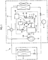
- a refrigerant circuit diagram which includes an oil return circuit for a refrigerating cycle according to an embodiment of the present invention is shown
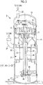
- Fig. 2 a longitudinal sectional view of a low-pressure housing type compressor which is applied to the refrigerating cycle is shown.
- a refrigerating cycle 1 here is a refrigerating cycle filled with a R32 refrigerant or a R32-rich mixed refrigerant (hereinafter, referred to simply as a R32 refrigerant) as a refrigerant and is a heat pump cycle which is provided with a four-way switching valve 4 and allows cooling and heating to be performed by switching a refrigerant circulation direction.
- a R32 refrigerant a R32-rich mixed refrigerant
- it may be a single cycle for refrigeration or a heat pump.
- the refrigerating cycle 1 is configured by a closed cycle refrigerant cycle in which a low-pressure housing type compressor 2, an oil separator 3 provided in a discharge circuit 13A of the compressor 2, the four-way switching valve 4 which switches a refrigerant circulation direction, an outdoor-side heat exchanger 6 to which a blower 5 is attached, an electronic expansion valve for heating 7, a receiver 8, an electronic expansion valve for cooling 9, an indoor-side heat exchanger 11 to which a blower 10 is attached, and an accumulator 12 provided in a suction circuit 13B of the compressor 2 are sequentially connected by refrigerant piping 13.
- the compressor 2 is a hermetic type electric scroll compressor 2, as shown in Fig. 2 .
- the hermetic type electric scroll compressor 2 is a compressor which is provided with a longitudinally elongated cylinder-shaped housing 14 having a hermetic structure configuring an outer shell and in which a scroll compression mechanism 15 is incorporated into an upper portion of the inside of the housing 14.
- the scroll compression mechanism 15 is provided with a pair of fixed scroll 16 and orbiting scroll 17, as well known, and is incorporated through a bearing member 18 fixedly installed in the housing 14.
- a configuration is made in which a high-pressure refrigerant gas compressed by the scroll compression mechanism 15 is discharged into a discharge chamber 19 and sent to the discharge circuit 13A on the refrigerating cycle 1 side through a discharge pipe 20.
- a motor 21 composed of a stator 22 and a rotor 23 is fixedly installed below the scroll compression mechanism 15.
- a driving shaft 24 is integrally joined to the rotor 23 of the motor 21, and a crankpin provided at an upper end of the driving shaft 24 is connected to the back surface of the orbiting scroll 17 of the scroll compression mechanism 15 through a drive bush and a slewing bearing, whereby the scroll compression mechanism 15 can be driven.
- the upper end side of the driving shaft 24 is supported by the bearing member 18, and a lower end portion is supported by a bearing member 25 installed at a lower portion in the housing 14.
- An oil supply pump 26 is provided between the lower end portion of the driving shaft 24 and the bearing member 25, and thus a configuration is made in which lubricating oil (oil) filled in an oil reservoir 27 of an inner bottom portion of the housing 14 can be supplied to a sliding part of the scroll compression mechanism 15 through an oil supply hole 28 provided in the driving shaft 24.
- the hermetic type electric scroll compressor 2 provided with such an oil supply mechanism is well known.
- the compressor 2 does not need to be the hermetic type electric scroll compressor 2 as described above and may be an open type scroll compressor having an oil reservoir in a housing, or other types of compressor other than a scroll compressor.
- the lubricating oil (oil) which is filled in the oil reservoir 27 in the housing 14 is PVE oil (polyvinyl ether-based oil), POE oil (polyol ester-based oil), or PAG oil (polyalkylene glycol-based oil) having adaptability to the R32 refrigerant, or mixed oil containing them as its main component, and oil having viscosity in a range of about 20 to 150 cP at 40°C is used.
- a suction pipe 29 is provided at an outer peripheral portion of the housing 14 so as to be open to a space portion between the motor 21 and the scroll compression mechanism 15, and the compressor 2 is connected to the suction circuit 13B on the refrigerating cycle 1 side through the suction pipe 29.
- the hermetic type electric scroll compressor 2 is regarded as the low-pressure housing type compressor 2 in which the inside of the housing 14 has a low-pressure atmosphere.
- An oil return circuit 31 for returning oil separated by the oil separator 3 provided in the discharge circuit 13A on the refrigerating cycle 1 side to the oil reservoir 27 on the compressor 2 side is connected to the housing 14 of the hermetic type electric scroll compressor 2, as shown in Fig. 1 .
- the oil return circuit 31 is configured by a parallel circuit composed of a direct circuit 32 which directly returns oil separated by the oil separator 3 to the oil reservoir 27 through an electromagnetic valve 33 and a capillary tube 34 for pressure reduction and flow rate adjustment, and a cooling circuit 35 which is connected in parallel to the direct circuit 32 and returns the oil from the oil separator 3 to the oil reservoir 27 through an electromagnetic valve 36, an oil cooler 37, and a capillary tube 38 for pressure reduction and flow rate adjustment.
- a cold source for cooling oil by the oil cooler 37 As a cold source for cooling oil by the oil cooler 37, a part of a high-pressure liquid refrigerant circulating in the refrigerant circuit of the refrigerating cycle 1, a gas-liquid two-phase refrigerant decompressed by the expansion valve, a low-pressure gas refrigerant, or the like is used, and it is possible to adopt a refrigerant cooling type which performs cooling by heat exchange with a refrigerant, an air cooling type which performs cooling by air cooling using the blower 5 attached to the outdoor-side heat exchanger 6, or the like.
- the oil return circuit 31 has a configuration in which in order to limit an oil temperature rise in the housing 14 of the compressor 2 to a value less than or equal to a specified value, at least one of a discharge temperature of the refrigerant and an oil temperature or oil viscosity in the compressor 2 is detected, and when a detection value exceeds a threshold value set in advance, the oil return circuit 31 is switched from the direct circuit 32 to the cooling circuit 35, so that return oil can be cooled to a temperature less than or equal to a predetermined temperature and then returned to the oil reservoir 27.
- the oil return circuit 31 has a configuration in which it is provided with an oil temperature control unit 42 which controls opening and closing of the electromagnetic valves 33 and 36 so as to switch the oil return circuit 31 from the direct circuit 32 to the cooling circuit 35, when at least one of a detection value of a discharge temperature sensor 39 provided in the discharge circuit 13A of the refrigerating cycle 1, a detection value of an oil temperature sensor 40 provided at the bottom portion of the housing of the compressor 2, the oil viscosity calculated based on the detection values of a low-pressure pressure sensor 41 provided in the suction circuit 13B of the refrigerating cycle 1 and the oil temperature sensor 40, and the like exceeds a threshold value set in advance, and the return oil from the oil separator 3 is cooled to a temperature less than or equal to a predetermined temperature by the oil cooler 37 and then returned to the oil reservoir 27.
- an oil temperature control unit 42 which controls opening and closing of the electromagnetic valves 33 and 36 so as to switch the oil return circuit 31 from the direct circuit 32 to the cooling circuit 35, when at least one of a
- a cooling operation can be performed by circulating a high-temperature and high-pressure refrigerant gas discharged from the compressor 2 to the outdoor-side heat exchanger 6 side by the four-way switching valve 4 and causing the outdoor-side heat exchanger 6 to function as a condenser and the indoor-side heat exchanger 11 to function as an evaporator
- a heating operation can be performed by circulating the high-temperature and high-pressure refrigerant gas to the indoor-side heat exchanger 11 side by the four-way switching valve 4 and causing the indoor-side heat exchanger 11 to function as a condenser and the outdoor-side heat exchanger 6 to function as an evaporator.
- oil contained in the discharged refrigerant gas from the compressor 2 is separated by the oil separator 3 provided in the discharge circuit 13A and returned to the oil reservoir 27 of the hermetic type electric scroll compressor 2 which is a low-pressure housing type through the oil return circuit 31.
- the oil return circuit 31 is a parallel circuit composed of the direct circuit 32 which directly returns oil to the oil reservoir 27 and the cooling circuit 35 which cools oil by the oil cooler 37 and then returns it to the oil reservoir 27. For this reason, in a case where the discharge temperature of the refrigerant which is discharged from the compressor 2 rises and there is a possibility that the oil temperature in the compressor 2 may exceed a threshold value set in advance, it is detected and the oil return circuit 31 is switched from the direct circuit 32 to the cooling circuit 35, so that the return oil can be cooled to a temperature less than or equal to a predetermined temperature by the oil cooler 37 and then returned to the oil reservoir 27.
- the oil temperature control unit 42 detects at least one of the discharge temperature of the refrigerant which is discharged from the compressor 2 and the oil temperature or the oil viscosity in the compressor 2, on the basis of the detection values of the discharge temperature sensor 39, the oil temperature sensor 40, and the low-pressure pressure sensor 41, and functions, when it exceeds the threshold value set in advance, so as to limit an oil temperature rise in the compressor 2 to a value less than or equal to a specified value by closing the electromagnetic valve 33 from the open state and opening the electromagnetic valve 36 from the closed state, thereby switching the oil return circuit 31 from the direct circuit 32 to the cooling circuit 35 to cool the return oil to a temperature less than or equal to a predetermined temperature and returning the return oil to the oil reservoir 27.
- the threshold values of the discharge temperature of the refrigerant, the oil temperature in the compressor, and the oil viscosity are set, and when the respective detection values exceed the threshold values, by performing control through the oil temperature control unit 42 so as to switch the oil return circuit 31 from the direct circuit 32 to the cooling circuit 35 to cool the return oil by the oil cooler 37 such that the temperature is lowered by approximately 15 deg and then return the return oil to the oil reservoir 27, it is possible to reduce the oil temperature to the same temperature as in the case of the R410A refrigerant and make the oil viscosity approximately equivalent to that of the R410A refrigerant, and thus it is possible to secure an allowable operating range or condition equivalent to that for the R410A refrigerant.
- the viscosity of oil depends on solubility in a refrigerant, which is determined according to pressure and a temperature, and it is possible to grasp the viscosity of oil by measuring a temperature and pressure with the oil temperature sensor 40 and the low-pressure pressure sensor 41, as described above, and determining solubility from a pressure/solubility characteristic diagram or the like using the temperature as a parameter.
- the oil return circuit 31 is switched from the direct circuit 32 which directly returns oil from the oil separator 3 to the oil reservoir 27 of the compressor 2 to the side of the cooling circuit 35 which cools oil by the oil cooler 37 and then returns the oil to the oil reservoir 27, and thus the oil is cooled to a temperature less than or equal to a predetermined temperature by the oil cooler 37 and then returned to the oil reservoir 27 in the housing 14 of the compressor 2, whereby it is possible to limit an oil temperature rise in the compressor 2 to a value less than or equal to a specified value.
- the oil separated by the oil separator 3 can be directly returned to the oil reservoir 27 in the housing 14 of the compressor 2, and therefore, it is possible to prevent re-mixing with a refrigerant gas and suppress an increase in oil circulation rate in order to hold the returned oil in the oil reservoir, and it is only necessary to cool oil only when necessary, and thus it is possible to minimize the influence on the capacity or the performance of the refrigerating cycle 1.
- the compressor 2 is the low-pressure housing type scroll compressor 2 of either a hermetic type or an open type, and the oil reservoir 27 in the housing 14 is filled with any oil of PVE oil, POE oil, and PAG oil, or mixed oil containing them as its main component.
- the oil return circuit 31 is a parallel circuit composed of the direct circuit 32 which directly returns the oil separated by the oil separator 3 from the oil separator 3 to the oil reservoir 27 and the cooling circuit 35 which cools the oil by the oil cooler 37 and then returns it to the oil reservoir 27, and when at least one of the detection values of the discharge temperature of the refrigerant and the oil temperature or the oil viscosity in the compressor 2 exceeds a threshold value, the oil return circuit 31 is switched from the direct circuit 32 to the cooling circuit 35.
- the return oil is cooled to a temperature less than or equal to a predetermined temperature by the oil cooler 37 and then returned to the oil reservoir 27, and therefore, it is possible to reliably limit an oil temperature rise in the compressor 2 to a value less than or equal to a specified value, and it is only necessary to cool the oil by the oil cooler 37 only when necessary, and thus it is possible to minimize the influence on the capacity or the performance of the refrigerating cycle 1.
- the present invention is not limited to the invention according to the above-described embodiment and can be appropriately modified within a scope which does not depart from the gist of the invention.
- the discharge temperature sensor 39, the oil temperature sensor 40, and the low-pressure pressure sensor 41 are provided to detect the discharge temperature of the refrigerant and the oil temperature or the oil viscosity in the compressor 2.
- a configuration may be made such that sensors which are provided for the operation control of the refrigerating cycle 1 are applied to these sensors and the electromagnetic valves 33 and 36 are controlled by using the detection values thereof, and thus it is not necessary to newly install sensors.
Landscapes
- Engineering & Computer Science (AREA)
- Physics & Mathematics (AREA)
- Mechanical Engineering (AREA)
- Thermal Sciences (AREA)
- General Engineering & Computer Science (AREA)
- Chemical & Material Sciences (AREA)
- Analytical Chemistry (AREA)
- Power Engineering (AREA)
- Applications Or Details Of Rotary Compressors (AREA)
- Compressor (AREA)
- Rotary Pumps (AREA)
Abstract
Description
- The present invention relates to an oil return circuit and an oil return method for a refrigerating cycle using a R32 refrigerant or a R32 refrigerant-rich mixed refrigerant (hereinafter, referred to simply as a R32 refrigerant), in which a global warming potential (hereinafter, referred to as GWP) is low.
- A R32 refrigerant has an ozone depletion potential (ODP) of zero and a low GWP of about 1/3 of that of a R410A refrigerant, and therefore, the R32 refrigerant can contribute to a reduction of environmental burden and is used as an alternative refrigerant for the R410A refrigerant. However, in the R32 refrigerant, a discharge gas temperature rises by a temperature in a range of about 10 to 20°C, as compared with the R410A refrigerant, and the discharge gas temperature tends to rise as a pressure ratio between suction pressure and discharge pressure increases, and thus an oil temperature in a compressor rises due to return oil from an oil separator. When associated with this, oil viscosity decreases, and therefore, it is necessary to limit an allowable operating range or condition, compared to the R410A refrigerant.
- PTL 1 discloses a refrigerating cycle in which an oil separator is provided in a discharge circuit of a compressor, and during the cooling operation, a refrigerant containing oil discharged from the compressor is directly cooled from the oil separator through a first bypass flow path by a cooler and then returned into a housing of the compressor, where the oil is separated, and only the refrigerant is circulated to a condenser through a second bypass flow path, whereby an oil temperature rise in the compressor is suppressed.
- During the heating operation, the refrigerant and the oil are separated from each other by the oil separator, the refrigerant is circulated to the condenser to be provided for heating, and the oil is cooled through the first bypass flow path and the cooler and then returned to the compressor, whereby a rise in oil temperature and a decrease in heating capacity are suppressed.
- On the other hand, in a refrigerating cycle using the R410A refrigerant or the like, conventionally, an oil separator is provided in a discharge circuit of a compressor, oil contained in a refrigerant gas is separated by the oil separator, and a refrigerant is then circulated to a condenser, and such refrigerating cycles are disclosed in
PTL 2 toPTL 5. - In these refrigerating cycles, the separated oil is returned to the compressor or a suction circuit of the compressor by an oil return circuit, alternatively, an oil cooler is provided in the oil return circuit and the oil is cooled as necessary and then returned to the compressor side.
-
- [PTL 1] Japanese Unexamined Patent Application Publication No.
2014-85104 - [PTL 2] Japanese Unexamined Patent Application Publication No.
6-337171 - [PTL 3] Japanese Unexamined Patent Application Publication No.
11-83204 - [PTL 4] Japanese Unexamined Patent Application Publication No.
2005-214515 - [PTL 5] Japanese Unexamined Patent Application Publication No.
2006-170570 - However, in the refrigerating cycle of PTL 1 described above, the inside of the housing of the compressor must have not only a high-pressure atmosphere but also an oil separating function, and the compressor must have a direct suction and direct discharge structure. Furthermore, each of the first bypass flow path and the second bypass flow path must be formed by high-pressure gas piping having a relatively large diameter, and thus a compressor structure and a piping structure around it become complicated and expensive, and there is a problem such as being unable to be applied to a refrigerating cycle using a low-pressure housing type compressor.
- On the other hand, in a refrigerating cycle using a low-pressure housing type compressor in which the inside of a housing is under a low-pressure atmosphere, only the oil separated by an oil separator can be returned to the compressor side through an oil return circuit, as shown in
PTL 2 toPTL 5. At this time, by returning the oil to a suction circuit of the compressor, it is possible to cool the oil with a low-pressure refrigerant gas and return it to the compressor with an oil temperature lowered. However, in this case, the oil and the refrigerant gas are remixed, and therefore, they must be separated again in the compressor, and thus there is a problem such as an oil rise due to a decrease in oil separation efficiency, that is, an increase in oil circulation rate. - Further, a technique has been also proposed in which an oil cooler is provided in an oil return circuit such that the oil cooled there is directly returned to an oil reservoir of a compressor housing. However, in this case, the oil is constantly cooled by the oil cooler, and therefore, in a case where a refrigerant is used as a cold source in the oil cooler, there is a problem such as the capacity or the performance of a refrigerating cycle being affected.
- The present invention has been made in view of such circumstances and has an object to provide an oil return circuit and an oil return method for a refrigerating cycle in which even in a case of using a R32 refrigerant in which a discharge gas temperature becomes high, it is possible to suppress a rise in oil temperature in a compressor and secure an allowable operating range or condition equivalent to that for a R410A refrigerant, and it is possible to suppress an increase in oil circulation rate or the influence on the capacity or the performance of the refrigerating cycle.
- In order to solve the above-described problems, an oil return circuit and an oil return method for a refrigerating cycle according to the present invention adopt the following means.
- That is, an oil return circuit for a refrigerating cycle according to the present invention includes: a refrigerating cycle which is provided with a compressor in which an inside of a housing having an oil reservoir has a low-pressure atmosphere, and has a R32 refrigerant or a R32-rich mixed refrigerant filled in the cycle; an oil separator provided in a discharge circuit from the compressor; and an oil return circuit in which the separated oil by the oil separator is depressurized and the oil returns to the oil reservoir in the housing, in which the oil return circuit is a parallel circuit composed of a direct circuit which directly returns oil from the oil separator to the oil reservoir and a cooling circuit which cools oil by an oil cooler and returns the cooled oil to the oil reservoir, and is provided with an oil temperature control unit which detects at least one of a discharge temperature of the refrigerant and an oil temperature or oil viscosity in the compressor, and when it exceeds a threshold value set in advance, switches the oil return circuit from the direct circuit to the cooling circuit to cool return oil to a temperature less than or equal to a predetermined temperature and return the oil to the oil reservoir.
- According to the present invention, even in a case where a discharge gas temperature rises due to using the
- R32 refrigerant or the R32-rich mixed refrigerant, at least one of the discharge temperature of the refrigerant and the oil temperature or the oil viscosity in the compressor is detected, and when it exceeds the threshold value set in advance, the oil return circuit is switched from the direct circuit to the cooling circuit so as to cool oil to a temperature less than or equal to a predetermined temperature by the oil cooler and return the cooled oil to the oil reservoir in the housing of the compressor, whereby it is possible to limit an oil temperature rise in the compressor to a value less than or equal to a specified value. Therefore, it is possible to suppress a rise in oil temperature in the compressor and secure an allowable operating range or condition equivalent to that for the R410A refrigerant. Further, the oil separated by the oil separator can be directly returned to the oil reservoir in the housing, and therefore, it is possible to prevent re-mixing with the refrigerant gas and suppress an increase in oil circulation rate in order to hold the returned oil in the oil reservoir, and it is only necessary to cool oil only when necessary, and thus it is possible to minimize the influence on the capacity or the performance of the refrigerating cycle.
- Further, in an oil return circuit for a refrigerating cycle according to the present invention, in the oil return circuit for a refrigerating cycle described above, the compressor is a low-pressure housing type scroll compressor of either a hermetic type or an open type, and the oil reservoir in the housing is filled with PVE oil, POE oil, PAG oil, or a mixed oil containing them as its main component.
- According to the present invention, a low-pressure housing type scroll compressor of a hermetic type or an open type for a R410A refrigerant configured to suction a low-pressure refrigerant gas from the refrigerating cycle side into the housing, suction and compress the refrigerant, and discharge it to a discharge chamber can be applied as it is.
- In this case, PVE oil (polyvinyl ether-based oil), POE oil (polyol ester-based oil), PAG oil (polyalkylene glycol-based oil), or mixed oil thereof adapted to the refrigerant is filled, whereby it is possible to configure a refrigerating cycle using the R32 refrigerant or the R32-rich mixed refrigerant and operate the refrigerating cycle while securing an allowable operating range or condition equivalent to that for the R410A refrigerant.
- Therefore, it is possible to reliably eliminate poor lubrication or the like caused by a decrease in oil viscosity due to an oil temperature rise in the compressor. Further, in a case where the compressor is an open type compressor, effects such as being able to suppress generation of oil sludge associated with a rise in the temperature of a sliding part at a shaft seal portion due to a mechanical seal or a lip seal and prevent refrigerant leakage are exhibited.
- Further, an oil return method for a refrigerating cycle according to the present invention is an oil return method for a refrigerating cycle in which an oil separator is provided in a discharge circuit of the compressor of the refrigerating cycle which is provided with a low-pressure housing type compressor and has a R32 refrigerant or a R32-rich mixed refrigerant filled in the cycle, and oil separated by the oil separator is returned to an oil reservoir in a housing of the compressor through an oil return circuit, the oil return method including: detecting at least one of a discharge temperature of the refrigerant and an oil temperature or oil viscosity in the compressor; and limiting an oil temperature rise in the compressor to a value less than or equal to a specified value, when a detection value exceeds a threshold value set in advance, by cooling return oil to a temperature less than or equal to a predetermined temperature by an oil cooler provided in the oil return circuit and returning the oil to the oil reservoir.
- According to the present invention, even in a case where a discharge gas temperature rises due to using the R32 refrigerant or the R32-rich mixed refrigerant, at least one of the discharge temperature of the refrigerant and the oil temperature or the oil viscosity in the compressor is detected, and when the detection value exceeds a threshold value set in advance, return oil is cooled to a temperature less than or equal to a predetermined temperature by the oil cooler provided in the oil return circuit and returned to the oil reservoir in the housing of the compressor, whereby it is possible to limit an oil temperature rise in the compressor to a value less than or equal to a specified value.
- Therefore, it is possible to suppress a rise in oil temperature in the compressor and secure an allowable operating range or condition equivalent to that for the R410A refrigerant. Further, the oil separated by the oil separator can be directly returned to the oil reservoir in the housing, and therefore, it is possible to prevent re-mixing with the refrigerant gas and suppress an increase in oil circulation rate in order to hold the returned oil in the oil reservoir, and it is only necessary to cool oil only when necessary, and thus it is possible to minimize the influence on the capacity or the performance of the refrigerating cycle.
- Further, in an oil return method for a refrigerating cycle according to the present invention, in the oil return method for a refrigerating cycle described above, the oil return circuit is a parallel circuit composed of a direct circuit which directly returns oil from the oil separator to the oil reservoir and a cooling circuit which cools oil by the oil cooler and returns the cooled oil to the oil reservoir, and when at least one of detection values of the discharge temperature of the refrigerant and the oil temperature or the oil viscosity in the compressor exceeds the threshold value, the oil return circuit is switched from the direct circuit to the cooling circuit to cool return oil to a temperature less than or equal to a predetermined temperature by the oil cooler and return the oil to the oil reservoir.
- According to the present invention, when at least one of the detection values of the discharge temperature of the refrigerant and the oil temperature or the oil viscosity in the compressor is less than or equal to the threshold value, oil is directly returned from the oil separator to the oil reservoir through the direct circuit, and when the detection value exceeds the threshold value, oil can be cooled to a temperature less than or equal to a predetermined temperature by the oil cooler of the cooling circuit and then returned to the oil reservoir. Therefore, it is possible to reliably limit an oil temperature rise in the compressor to a value less than or equal to a specified value, and it is only necessary to cool oil by the oil cooler only when necessary, and thus it is possible to minimize the influence on the capacity or the performance of the refrigerating cycle.
- According to the oil return circuit and an oil return method for a refrigerating cycle according to the present invention, even in a case where the discharge gas temperature rises due to using the R32 refrigerant or the R32-rich mixed refrigerant, at least one of the discharge temperature of the refrigerant and the oil temperature or the oil viscosity in the compressor is detected, and when it exceeds the threshold value set in advance, the oil return circuit is switched from the direct circuit to the cooling circuit so as to cool oil to a temperature less than or equal to a predetermined temperature by the oil cooler and return the cooled oil to the oil reservoir in the housing of the compressor, whereby it is possible to limit an oil temperature rise in the compressor to a value less than or equal to a specified value.
- For this reason, it is possible to suppress a rise in oil temperature in the compressor and secure an allowable operating range or condition equivalent to that for the R410A refrigerant. Further, the oil separated by the oil separator can be directly returned to the oil reservoir in the compressor, and therefore, it is possible to prevent re-mixing with the refrigerant gas and suppress an increase in oil circulation rate in order to hold the returned oil in the oil reservoir, and it is only necessary to cool oil only when necessary, and thus it is possible to minimize the influence on the capacity or the performance of the refrigerating cycle.
-
-
Fig. 1 is a refrigerant circuit diagram which includes an oil return circuit for a refrigerating cycle according to an embodiment of the present invention. -
Fig. 2 is a longitudinal sectional view of a low-pressure housing type compressor which is applied to the refrigerating cycle. - Hereinafter, an embodiment of the present invention will be described using
Figs. 1 and2 . - In
Fig. 1 , a refrigerant circuit diagram which includes an oil return circuit for a refrigerating cycle according to an embodiment of the present invention is shown, and inFig. 2 , a longitudinal sectional view of a low-pressure housing type compressor which is applied to the refrigerating cycle is shown. - A refrigerating cycle 1 here is a refrigerating cycle filled with a R32 refrigerant or a R32-rich mixed refrigerant (hereinafter, referred to simply as a R32 refrigerant) as a refrigerant and is a heat pump cycle which is provided with a four-
way switching valve 4 and allows cooling and heating to be performed by switching a refrigerant circulation direction. However, it may be a single cycle for refrigeration or a heat pump. - The refrigerating cycle 1 is configured by a closed cycle refrigerant cycle in which a low-pressure
housing type compressor 2, anoil separator 3 provided in adischarge circuit 13A of thecompressor 2, the four-way switching valve 4 which switches a refrigerant circulation direction, an outdoor-side heat exchanger 6 to which ablower 5 is attached, an electronic expansion valve forheating 7, a receiver 8, an electronic expansion valve for cooling 9, an indoor-side heat exchanger 11 to which ablower 10 is attached, and anaccumulator 12 provided in asuction circuit 13B of thecompressor 2 are sequentially connected byrefrigerant piping 13. - The
compressor 2 is a hermetic typeelectric scroll compressor 2, as shown inFig. 2 . The hermetic typeelectric scroll compressor 2 is a compressor which is provided with a longitudinally elongated cylinder-shaped housing 14 having a hermetic structure configuring an outer shell and in which ascroll compression mechanism 15 is incorporated into an upper portion of the inside of thehousing 14. Thescroll compression mechanism 15 is provided with a pair offixed scroll 16 and orbitingscroll 17, as well known, and is incorporated through abearing member 18 fixedly installed in thehousing 14. A configuration is made in which a high-pressure refrigerant gas compressed by thescroll compression mechanism 15 is discharged into adischarge chamber 19 and sent to thedischarge circuit 13A on the refrigerating cycle 1 side through adischarge pipe 20. - In the
housing 14, amotor 21 composed of astator 22 and arotor 23 is fixedly installed below thescroll compression mechanism 15. Adriving shaft 24 is integrally joined to therotor 23 of themotor 21, and a crankpin provided at an upper end of the drivingshaft 24 is connected to the back surface of the orbitingscroll 17 of thescroll compression mechanism 15 through a drive bush and a slewing bearing, whereby thescroll compression mechanism 15 can be driven. - The upper end side of the driving
shaft 24 is supported by thebearing member 18, and a lower end portion is supported by abearing member 25 installed at a lower portion in thehousing 14. Anoil supply pump 26 is provided between the lower end portion of thedriving shaft 24 and thebearing member 25, and thus a configuration is made in which lubricating oil (oil) filled in anoil reservoir 27 of an inner bottom portion of thehousing 14 can be supplied to a sliding part of thescroll compression mechanism 15 through anoil supply hole 28 provided in thedriving shaft 24. The hermetic typeelectric scroll compressor 2 provided with such an oil supply mechanism is well known. - The
compressor 2 does not need to be the hermetic typeelectric scroll compressor 2 as described above and may be an open type scroll compressor having an oil reservoir in a housing, or other types of compressor other than a scroll compressor. - The lubricating oil (oil) which is filled in the
oil reservoir 27 in thehousing 14 is PVE oil (polyvinyl ether-based oil), POE oil (polyol ester-based oil), or PAG oil (polyalkylene glycol-based oil) having adaptability to the R32 refrigerant, or mixed oil containing them as its main component, and oil having viscosity in a range of about 20 to 150 cP at 40°C is used. - In this embodiment, a
suction pipe 29 is provided at an outer peripheral portion of thehousing 14 so as to be open to a space portion between themotor 21 and thescroll compression mechanism 15, and thecompressor 2 is connected to thesuction circuit 13B on the refrigerating cycle 1 side through thesuction pipe 29. In this way, the hermetic typeelectric scroll compressor 2 is regarded as the low-pressurehousing type compressor 2 in which the inside of thehousing 14 has a low-pressure atmosphere. - An
oil return circuit 31 for returning oil separated by theoil separator 3 provided in thedischarge circuit 13A on the refrigerating cycle 1 side to theoil reservoir 27 on thecompressor 2 side is connected to thehousing 14 of the hermetic typeelectric scroll compressor 2, as shown inFig. 1 . Theoil return circuit 31 is configured by a parallel circuit composed of adirect circuit 32 which directly returns oil separated by theoil separator 3 to theoil reservoir 27 through anelectromagnetic valve 33 and acapillary tube 34 for pressure reduction and flow rate adjustment, and acooling circuit 35 which is connected in parallel to thedirect circuit 32 and returns the oil from theoil separator 3 to theoil reservoir 27 through anelectromagnetic valve 36, anoil cooler 37, and acapillary tube 38 for pressure reduction and flow rate adjustment. - As a cold source for cooling oil by the
oil cooler 37, a part of a high-pressure liquid refrigerant circulating in the refrigerant circuit of the refrigerating cycle 1, a gas-liquid two-phase refrigerant decompressed by the expansion valve, a low-pressure gas refrigerant, or the like is used, and it is possible to adopt a refrigerant cooling type which performs cooling by heat exchange with a refrigerant, an air cooling type which performs cooling by air cooling using theblower 5 attached to the outdoor-side heat exchanger 6, or the like. - The
oil return circuit 31 has a configuration in which in order to limit an oil temperature rise in thehousing 14 of thecompressor 2 to a value less than or equal to a specified value, at least one of a discharge temperature of the refrigerant and an oil temperature or oil viscosity in thecompressor 2 is detected, and when a detection value exceeds a threshold value set in advance, theoil return circuit 31 is switched from thedirect circuit 32 to thecooling circuit 35, so that return oil can be cooled to a temperature less than or equal to a predetermined temperature and then returned to theoil reservoir 27. - That is, the
oil return circuit 31 has a configuration in which it is provided with an oiltemperature control unit 42 which controls opening and closing of theelectromagnetic valves oil return circuit 31 from thedirect circuit 32 to thecooling circuit 35, when at least one of a detection value of adischarge temperature sensor 39 provided in thedischarge circuit 13A of the refrigerating cycle 1, a detection value of anoil temperature sensor 40 provided at the bottom portion of the housing of thecompressor 2, the oil viscosity calculated based on the detection values of a low-pressure pressure sensor 41 provided in thesuction circuit 13B of the refrigerating cycle 1 and theoil temperature sensor 40, and the like exceeds a threshold value set in advance, and the return oil from theoil separator 3 is cooled to a temperature less than or equal to a predetermined temperature by theoil cooler 37 and then returned to theoil reservoir 27. - With the configuration described above, according to this embodiment, the following operation and effects are exhibited.
- In the refrigerating cycle 1 described above, a cooling operation can be performed by circulating a high-temperature and high-pressure refrigerant gas discharged from the
compressor 2 to the outdoor-side heat exchanger 6 side by the four-way switching valve 4 and causing the outdoor-side heat exchanger 6 to function as a condenser and the indoor-side heat exchanger 11 to function as an evaporator, and a heating operation can be performed by circulating the high-temperature and high-pressure refrigerant gas to the indoor-side heat exchanger 11 side by the four-way switching valve 4 and causing the indoor-side heat exchanger 11 to function as a condenser and the outdoor-side heat exchanger 6 to function as an evaporator. - During this time, oil contained in the discharged refrigerant gas from the
compressor 2 is separated by theoil separator 3 provided in thedischarge circuit 13A and returned to theoil reservoir 27 of the hermetic typeelectric scroll compressor 2 which is a low-pressure housing type through theoil return circuit 31. - The
oil return circuit 31 is a parallel circuit composed of thedirect circuit 32 which directly returns oil to theoil reservoir 27 and thecooling circuit 35 which cools oil by theoil cooler 37 and then returns it to theoil reservoir 27. For this reason, in a case where the discharge temperature of the refrigerant which is discharged from thecompressor 2 rises and there is a possibility that the oil temperature in thecompressor 2 may exceed a threshold value set in advance, it is detected and theoil return circuit 31 is switched from thedirect circuit 32 to thecooling circuit 35, so that the return oil can be cooled to a temperature less than or equal to a predetermined temperature by theoil cooler 37 and then returned to theoil reservoir 27. - That is, the oil
temperature control unit 42 detects at least one of the discharge temperature of the refrigerant which is discharged from thecompressor 2 and the oil temperature or the oil viscosity in thecompressor 2, on the basis of the detection values of thedischarge temperature sensor 39, theoil temperature sensor 40, and the low-pressure pressure sensor 41, and functions, when it exceeds the threshold value set in advance, so as to limit an oil temperature rise in thecompressor 2 to a value less than or equal to a specified value by closing theelectromagnetic valve 33 from the open state and opening theelectromagnetic valve 36 from the closed state, thereby switching theoil return circuit 31 from thedirect circuit 32 to thecooling circuit 35 to cool the return oil to a temperature less than or equal to a predetermined temperature and returning the return oil to theoil reservoir 27. - Here, setting examples of the threshold value will be described. In a case where a combination of a refrigerant and refrigerating machine oil is R410A/PVE oil A or R32/PVE oil B, for example, when HP/LP is equal to 3.8/1.8 [MPa] and SH is equal to 10 [deg],
- (1) the discharge temperature of the refrigerant is 85°C in the R410A and 100°C in the R32, and therefore, the threshold value is set to 90°C, for example.
- (2) The oil temperature in the compressor is 70°C in the R410A and 85°C in the R32, and therefore, the threshold value is set to 75°C, for example.
- (3) The oil viscosity is 8 mm2/s in the R410A/PVE oil A and 6 mm2/s in the R32/PVE oil B, and therefore, the threshold value is set to 7.5 mm2/s, for example.
- As described above, the threshold values of the discharge temperature of the refrigerant, the oil temperature in the compressor, and the oil viscosity are set, and when the respective detection values exceed the threshold values, by performing control through the oil
temperature control unit 42 so as to switch theoil return circuit 31 from thedirect circuit 32 to thecooling circuit 35 to cool the return oil by theoil cooler 37 such that the temperature is lowered by approximately 15 deg and then return the return oil to theoil reservoir 27, it is possible to reduce the oil temperature to the same temperature as in the case of the R410A refrigerant and make the oil viscosity approximately equivalent to that of the R410A refrigerant, and thus it is possible to secure an allowable operating range or condition equivalent to that for the R410A refrigerant. - It is known that the viscosity of oil depends on solubility in a refrigerant, which is determined according to pressure and a temperature, and it is possible to grasp the viscosity of oil by measuring a temperature and pressure with the
oil temperature sensor 40 and the low-pressure pressure sensor 41, as described above, and determining solubility from a pressure/solubility characteristic diagram or the like using the temperature as a parameter. - As described above, even if there is a case where the discharge gas temperature of the refrigerant which is discharged from the
compressor 2 rises due to using the R32 refrigerant instead of the R410A refrigerant, at least one of the discharge temperature of the refrigerant and the oil temperature or the oil viscosity in thecompressor 2 is detected, and when it exceeds a threshold value set in advance, theoil return circuit 31 is switched from thedirect circuit 32 which directly returns oil from theoil separator 3 to theoil reservoir 27 of thecompressor 2 to the side of thecooling circuit 35 which cools oil by theoil cooler 37 and then returns the oil to theoil reservoir 27, and thus the oil is cooled to a temperature less than or equal to a predetermined temperature by theoil cooler 37 and then returned to theoil reservoir 27 in thehousing 14 of thecompressor 2, whereby it is possible to limit an oil temperature rise in thecompressor 2 to a value less than or equal to a specified value. - Therefore, it is possible to suppress a rise in the oil temperature in the
compressor 2 and secure an allowable operating range or condition equivalent to that for the R410A refrigerant. Further, the oil separated by theoil separator 3 can be directly returned to theoil reservoir 27 in thehousing 14 of thecompressor 2, and therefore, it is possible to prevent re-mixing with a refrigerant gas and suppress an increase in oil circulation rate in order to hold the returned oil in the oil reservoir, and it is only necessary to cool oil only when necessary, and thus it is possible to minimize the influence on the capacity or the performance of the refrigerating cycle 1. - The
compressor 2 is the low-pressure housingtype scroll compressor 2 of either a hermetic type or an open type, and theoil reservoir 27 in thehousing 14 is filled with any oil of PVE oil, POE oil, and PAG oil, or mixed oil containing them as its main component. For this reason, the low-pressure housingtype scroll compressor 2 of a hermetic type or an open type for the R410A refrigerant configured to suction a low-pressure refrigerant gas from the refrigerating cycle 1 side into thehousing 14, suction and compress the refrigerant, and discharge it to thedischarge chamber 19 is applied as it is, and PVE oil, POE oil, PAG oil, or mixed oil thereof adapted to the refrigerant is filled, whereby it is possible to configure the refrigerating cycle 1 using the R32 refrigerant and operate the refrigerating cycle 1 while securing an allowable operating range or condition equivalent to that for the R410A refrigerant. - In this way, it is possible to reliably eliminate a concern such as poor lubrication caused by a decrease in oil viscosity due to an oil temperature rise in the
compressor 2. In particular, in a case where thecompressor 2 is an open type compressor, it is also possible to expect effects such as being able to suppress generation of oil sludge associated with a rise in the temperature of a sliding part at a shaft seal portion by a mechanical seal or a lip seal and prevent refrigerant leakage. - Further, the
oil return circuit 31 is a parallel circuit composed of thedirect circuit 32 which directly returns the oil separated by theoil separator 3 from theoil separator 3 to theoil reservoir 27 and thecooling circuit 35 which cools the oil by theoil cooler 37 and then returns it to theoil reservoir 27, and when at least one of the detection values of the discharge temperature of the refrigerant and the oil temperature or the oil viscosity in thecompressor 2 exceeds a threshold value, theoil return circuit 31 is switched from thedirect circuit 32 to thecooling circuit 35. - In this way, the return oil is cooled to a temperature less than or equal to a predetermined temperature by the
oil cooler 37 and then returned to theoil reservoir 27, and therefore, it is possible to reliably limit an oil temperature rise in thecompressor 2 to a value less than or equal to a specified value, and it is only necessary to cool the oil by theoil cooler 37 only when necessary, and thus it is possible to minimize the influence on the capacity or the performance of the refrigerating cycle 1. - The present invention is not limited to the invention according to the above-described embodiment and can be appropriately modified within a scope which does not depart from the gist of the invention. For example, in the above-described embodiment, the
discharge temperature sensor 39, theoil temperature sensor 40, and the low-pressure pressure sensor 41 are provided to detect the discharge temperature of the refrigerant and the oil temperature or the oil viscosity in thecompressor 2. However, a configuration may be made such that sensors which are provided for the operation control of the refrigerating cycle 1 are applied to these sensors and theelectromagnetic valves -
- 1: refrigerating cycle
- 2: compressor (hermetic type electric scroll compressor)
- 3: oil separator
- 13A: discharge circuit
- 14: housing
- 27: oil reservoir
- 31: oil return circuit
- 32: direct circuit
- 33, 36: electromagnetic valve
- 34, 38: capillary tube
- 35: cooling circuit
- 37: oil cooler
- 39: discharge temperature sensor
- 40: oil temperature sensor
- 41: low-pressure pressure sensor
- 42: oil temperature control unit
Claims (4)
- An oil return circuit for a refrigerating cycle comprising:a refrigerating cycle which is provided with a compressor in which an inside of a housing having an oil reservoir has a low-pressure atmosphere, and has a R32 refrigerant or a R32-rich mixed refrigerant filled in the cycle;an oil separator provided in a discharge circuit from the compressor; andan oil return circuit in which the separated oil by the oil separator are depressurized and the oil returns to the oil reservoir in the housing,wherein the oil return circuitis a parallel circuit composed of a direct circuit which directly returns oil from the oil separator to the oil reservoir and a cooling circuit which cools oil by an oil cooler and returns the cooled oil to the oil reservoir, andis provided with an oil temperature control unit which detects at least one of a discharge temperature of the refrigerant and an oil temperature or oil viscosity in the compressor, and when it exceeds a threshold value set in advance, switches the oil return circuit from the direct circuit to the cooling circuit to cool return oil to a temperature less than or equal to a predetermined temperature and return the oil to the oil reservoir.
- The oil return circuit for a refrigerating cycle according to Claim 1, wherein the compressor is a low-pressure housing type scroll compressor of either a hermetic type or an open type, and the oil reservoir in the housing is filled with PVE oil, POE oil, PAG oil, or a mixed oil containing them as its main component.
- An oil return method for a refrigerating cycle in which an oil separator is provided in a discharge circuit of the compressor of the refrigerating cycle which is provided with a low-pressure housing type compressor and has a R32 refrigerant or a R32-rich mixed refrigerant filled in the cycle, and oil separated by the oil separator is returned to an oil reservoir in a housing of the compressor through an oil return circuit, the oil return method comprising:detecting at least one of a discharge temperature of the refrigerant and an oil temperature or oil viscosity in the compressor; andlimiting an oil temperature rise in the compressor to a value less than or equal to a specified value, when the detection value exceeds a threshold value set in advance, by cooling return oil to a temperature less than or equal to a predetermined temperature by an oil cooler provided in the oil return circuit and returning the oil to the oil reservoir.
- The oil return method for a refrigerating cycle according to Claim 3, wherein the oil return circuit is a parallel circuit composed of a direct circuit which directly returns oil from the oil separator to the oil reservoir and a cooling circuit which cools oil by the oil cooler and returns the cooled oil to the oil reservoir, and
when at least one of detection values of the discharge temperature of the refrigerant and the oil temperature or the oil viscosity in the compressor exceeds the threshold value, the oil return circuit is switched from the direct circuit to the cooling circuit to cool return oil to a temperature less than or equal to a predetermined temperature by the oil cooler and return the oil to the oil reservoir.
Applications Claiming Priority (2)
| Application Number | Priority Date | Filing Date | Title |
|---|---|---|---|
| JP2015036885A JP6495048B2 (en) | 2015-02-26 | 2015-02-26 | Oil return circuit and oil return method for refrigeration cycle |
| PCT/JP2016/050793 WO2016136305A1 (en) | 2015-02-26 | 2016-01-13 | Oil return circuit and oil return method for refrigerating cycle |
Publications (3)
| Publication Number | Publication Date |
|---|---|
| EP3249317A1 true EP3249317A1 (en) | 2017-11-29 |
| EP3249317A4 EP3249317A4 (en) | 2018-03-14 |
| EP3249317B1 EP3249317B1 (en) | 2019-04-24 |
Family
ID=56788097
Family Applications (1)
| Application Number | Title | Priority Date | Filing Date |
|---|---|---|---|
| EP16755055.7A Active EP3249317B1 (en) | 2015-02-26 | 2016-01-13 | Oil return circuit and oil return method for refrigerating cycle |
Country Status (6)
| Country | Link |
|---|---|
| EP (1) | EP3249317B1 (en) |
| JP (1) | JP6495048B2 (en) |
| KR (1) | KR102099665B1 (en) |
| CN (1) | CN107532824A (en) |
| AU (1) | AU2016225575B2 (en) |
| WO (1) | WO2016136305A1 (en) |
Cited By (1)
| Publication number | Priority date | Publication date | Assignee | Title |
|---|---|---|---|---|
| EP4509778A3 (en) * | 2019-05-03 | 2025-06-04 | Tyco Fire & Security GmbH | Vapor compression system |
Families Citing this family (11)
| Publication number | Priority date | Publication date | Assignee | Title |
|---|---|---|---|---|
| JP6704526B2 (en) * | 2017-07-25 | 2020-06-03 | 三菱電機株式会社 | Refrigeration cycle equipment |
| WO2019026270A1 (en) * | 2017-08-04 | 2019-02-07 | 三菱電機株式会社 | Refrigeration cycle device and heat source unit |
| CN109163479A (en) * | 2018-10-18 | 2019-01-08 | 中国科学院广州能源研究所 | A kind of automatic oil return gas engine heat pump system |
| KR20200071975A (en) * | 2018-12-12 | 2020-06-22 | 엘지전자 주식회사 | Air Conditioner |
| CN110440402B (en) * | 2019-07-02 | 2021-09-21 | 青岛海尔空调电子有限公司 | Air conditioner and oil return control method thereof |
| US12055323B2 (en) * | 2019-09-13 | 2024-08-06 | Carrier Corporation | Vapor compression system |
| WO2022085125A1 (en) * | 2020-10-21 | 2022-04-28 | 三菱電機株式会社 | Refrigeration cycle device |
| CN113483449B (en) * | 2021-07-09 | 2022-09-06 | 青岛海尔空调器有限总公司 | Oil return control method for indoor unit |
| CN114353360B (en) * | 2022-01-06 | 2024-02-23 | 青岛海尔空调电子有限公司 | Dual compressor refrigerant circulation system and control method thereof |
| CN116294259B (en) * | 2023-03-15 | 2026-03-20 | 龙志刚 | A refrigeration system |
| CN119755093B (en) * | 2024-12-30 | 2025-12-02 | 重庆超力高科技股份有限公司 | Oil return control methods, devices, control systems, vehicles and storage media |
Family Cites Families (17)
| Publication number | Priority date | Publication date | Assignee | Title |
|---|---|---|---|---|
| JPH06337171A (en) | 1993-03-30 | 1994-12-06 | Mitsubishi Heavy Ind Ltd | Refrigerating device |
| JPH0719634A (en) * | 1993-06-30 | 1995-01-20 | Mitsubishi Electric Corp | Compressor unit |
| JPH08152207A (en) * | 1994-11-29 | 1996-06-11 | Sanyo Electric Co Ltd | Air conditioner |
| JPH1183204A (en) | 1997-09-12 | 1999-03-26 | Mitsubishi Heavy Ind Ltd | Air conditioner |
| JP2002139261A (en) * | 2000-11-01 | 2002-05-17 | Mitsubishi Electric Corp | Refrigeration cycle device |
| JP2005083704A (en) * | 2003-09-10 | 2005-03-31 | Mitsubishi Electric Corp | Refrigeration cycle, air conditioner |
| JP2005214515A (en) * | 2004-01-29 | 2005-08-11 | Mitsubishi Heavy Ind Ltd | Refrigeration cycle device, compressor of refrigeration cycle device, and lubricant returning operation control method |
| JP2006170500A (en) * | 2004-12-14 | 2006-06-29 | Mitsubishi Heavy Ind Ltd | Air conditioner and operation method thereof |
| JP2006170570A (en) | 2004-12-17 | 2006-06-29 | Hitachi Ltd | Refrigeration equipment |
| JP5017037B2 (en) * | 2007-09-26 | 2012-09-05 | 三洋電機株式会社 | Refrigeration cycle equipment |
| JP4975052B2 (en) * | 2009-03-30 | 2012-07-11 | 三菱電機株式会社 | Refrigeration cycle equipment |
| CN101576337B (en) * | 2009-04-28 | 2010-09-08 | 浙江盾安机电科技有限公司 | Intelligent oil path control system |
| JP5502459B2 (en) * | 2009-12-25 | 2014-05-28 | 三洋電機株式会社 | Refrigeration equipment |
| DK2339266T3 (en) * | 2009-12-25 | 2018-05-28 | Sanyo Electric Co | Cooling device |
| JP5333305B2 (en) * | 2010-03-18 | 2013-11-06 | パナソニック株式会社 | Refrigeration cycle equipment |
| JP5903595B2 (en) * | 2011-05-27 | 2016-04-13 | パナソニックIpマネジメント株式会社 | Ultra-low temperature refrigeration equipment |
| JP5988828B2 (en) | 2012-10-29 | 2016-09-07 | ジョンソンコントロールズ ヒタチ エア コンディショニング テクノロジー(ホンコン)リミテッド | Refrigeration cycle equipment |
-
2015
- 2015-02-26 JP JP2015036885A patent/JP6495048B2/en active Active
-
2016
- 2016-01-13 KR KR1020177022335A patent/KR102099665B1/en active Active
- 2016-01-13 CN CN201680012020.8A patent/CN107532824A/en active Pending
- 2016-01-13 EP EP16755055.7A patent/EP3249317B1/en active Active
- 2016-01-13 AU AU2016225575A patent/AU2016225575B2/en active Active
- 2016-01-13 WO PCT/JP2016/050793 patent/WO2016136305A1/en not_active Ceased
Cited By (1)
| Publication number | Priority date | Publication date | Assignee | Title |
|---|---|---|---|---|
| EP4509778A3 (en) * | 2019-05-03 | 2025-06-04 | Tyco Fire & Security GmbH | Vapor compression system |
Also Published As
| Publication number | Publication date |
|---|---|
| EP3249317A4 (en) | 2018-03-14 |
| AU2016225575B2 (en) | 2018-11-01 |
| CN107532824A (en) | 2018-01-02 |
| EP3249317B1 (en) | 2019-04-24 |
| JP6495048B2 (en) | 2019-04-03 |
| WO2016136305A1 (en) | 2016-09-01 |
| KR20170102987A (en) | 2017-09-12 |
| JP2016161138A (en) | 2016-09-05 |
| KR102099665B1 (en) | 2020-04-10 |
| AU2016225575A1 (en) | 2017-08-24 |
Similar Documents
| Publication | Publication Date | Title |
|---|---|---|
| EP3249317B1 (en) | Oil return circuit and oil return method for refrigerating cycle | |
| JP5798830B2 (en) | Supercritical cycle heat pump | |
| EP3683524B1 (en) | Refrigeration apparatus | |
| EP2136158B1 (en) | Refrigerating device | |
| KR101841869B1 (en) | Refrigeration cycle device | |
| EP3575708B1 (en) | Refrigeration cycle device | |
| CN107429949B (en) | Refrigeration cycle device | |
| EP3136010B1 (en) | Air-conditioning device | |
| EP3222924B1 (en) | Air conditioning device | |
| KR20250143114A (en) | Pumps for HVAC&R systems | |
| CN112013557B (en) | Refrigerating apparatus | |
| EP3614071B1 (en) | Refrigeration cycle device | |
| EP2762803B1 (en) | Two-stage compression device and chilling/air-conditioning device using the same | |
| US20180223852A1 (en) | Compressor bearing housing drain | |
| US12352481B2 (en) | Refrigerant apparatus | |
| CN103486751A (en) | Refrigerating cycle device | |
| EP3098542B1 (en) | Refrigeration cycle device | |
| JP2013139898A (en) | Refrigeration apparatus | |
| JP2012137248A (en) | Refrigeration apparatus |
Legal Events
| Date | Code | Title | Description |
|---|---|---|---|
| STAA | Information on the status of an ep patent application or granted ep patent |
Free format text: STATUS: THE INTERNATIONAL PUBLICATION HAS BEEN MADE |
|
| PUAI | Public reference made under article 153(3) epc to a published international application that has entered the european phase |
Free format text: ORIGINAL CODE: 0009012 |
|
| STAA | Information on the status of an ep patent application or granted ep patent |
Free format text: STATUS: REQUEST FOR EXAMINATION WAS MADE |
|
| 17P | Request for examination filed |
Effective date: 20170824 |
|
| AK | Designated contracting states |
Kind code of ref document: A1 Designated state(s): AL AT BE BG CH CY CZ DE DK EE ES FI FR GB GR HR HU IE IS IT LI LT LU LV MC MK MT NL NO PL PT RO RS SE SI SK SM TR |
|
| AX | Request for extension of the european patent |
Extension state: BA ME |
|
| A4 | Supplementary search report drawn up and despatched |
Effective date: 20180209 |
|
| RIC1 | Information provided on ipc code assigned before grant |
Ipc: F25B 43/02 20060101ALI20180205BHEP Ipc: F25B 1/00 20060101AFI20180205BHEP Ipc: F25B 31/00 20060101ALI20180205BHEP Ipc: F25B 1/04 20060101ALI20180205BHEP |
|
| DAV | Request for validation of the european patent (deleted) | ||
| DAX | Request for extension of the european patent (deleted) | ||
| GRAP | Despatch of communication of intention to grant a patent |
Free format text: ORIGINAL CODE: EPIDOSNIGR1 |
|
| STAA | Information on the status of an ep patent application or granted ep patent |
Free format text: STATUS: GRANT OF PATENT IS INTENDED |
|
| INTG | Intention to grant announced |
Effective date: 20181220 |
|
| GRAS | Grant fee paid |
Free format text: ORIGINAL CODE: EPIDOSNIGR3 |
|
| GRAA | (expected) grant |
Free format text: ORIGINAL CODE: 0009210 |
|
| STAA | Information on the status of an ep patent application or granted ep patent |
Free format text: STATUS: THE PATENT HAS BEEN GRANTED |
|
| AK | Designated contracting states |
Kind code of ref document: B1 Designated state(s): AL AT BE BG CH CY CZ DE DK EE ES FI FR GB GR HR HU IE IS IT LI LT LU LV MC MK MT NL NO PL PT RO RS SE SI SK SM TR |
|
| REG | Reference to a national code |
Ref country code: GB Ref legal event code: FG4D |
|
| REG | Reference to a national code |
Ref country code: CH Ref legal event code: EP |
|
| REG | Reference to a national code |
Ref country code: AT Ref legal event code: REF Ref document number: 1124616 Country of ref document: AT Kind code of ref document: T Effective date: 20190515 Ref country code: IE Ref legal event code: FG4D |
|
| REG | Reference to a national code |
Ref country code: DE Ref legal event code: R096 Ref document number: 602016012941 Country of ref document: DE |
|
| REG | Reference to a national code |
Ref country code: NL Ref legal event code: MP Effective date: 20190424 |
|
| REG | Reference to a national code |
Ref country code: LT Ref legal event code: MG4D |
|
| PG25 | Lapsed in a contracting state [announced via postgrant information from national office to epo] |
Ref country code: NL Free format text: LAPSE BECAUSE OF FAILURE TO SUBMIT A TRANSLATION OF THE DESCRIPTION OR TO PAY THE FEE WITHIN THE PRESCRIBED TIME-LIMIT Effective date: 20190424 |
|
| PG25 | Lapsed in a contracting state [announced via postgrant information from national office to epo] |
Ref country code: LT Free format text: LAPSE BECAUSE OF FAILURE TO SUBMIT A TRANSLATION OF THE DESCRIPTION OR TO PAY THE FEE WITHIN THE PRESCRIBED TIME-LIMIT Effective date: 20190424 Ref country code: HR Free format text: LAPSE BECAUSE OF FAILURE TO SUBMIT A TRANSLATION OF THE DESCRIPTION OR TO PAY THE FEE WITHIN THE PRESCRIBED TIME-LIMIT Effective date: 20190424 Ref country code: SE Free format text: LAPSE BECAUSE OF FAILURE TO SUBMIT A TRANSLATION OF THE DESCRIPTION OR TO PAY THE FEE WITHIN THE PRESCRIBED TIME-LIMIT Effective date: 20190424 Ref country code: NO Free format text: LAPSE BECAUSE OF FAILURE TO SUBMIT A TRANSLATION OF THE DESCRIPTION OR TO PAY THE FEE WITHIN THE PRESCRIBED TIME-LIMIT Effective date: 20190724 Ref country code: ES Free format text: LAPSE BECAUSE OF FAILURE TO SUBMIT A TRANSLATION OF THE DESCRIPTION OR TO PAY THE FEE WITHIN THE PRESCRIBED TIME-LIMIT Effective date: 20190424 Ref country code: AL Free format text: LAPSE BECAUSE OF FAILURE TO SUBMIT A TRANSLATION OF THE DESCRIPTION OR TO PAY THE FEE WITHIN THE PRESCRIBED TIME-LIMIT Effective date: 20190424 Ref country code: PT Free format text: LAPSE BECAUSE OF FAILURE TO SUBMIT A TRANSLATION OF THE DESCRIPTION OR TO PAY THE FEE WITHIN THE PRESCRIBED TIME-LIMIT Effective date: 20190824 Ref country code: FI Free format text: LAPSE BECAUSE OF FAILURE TO SUBMIT A TRANSLATION OF THE DESCRIPTION OR TO PAY THE FEE WITHIN THE PRESCRIBED TIME-LIMIT Effective date: 20190424 |
|
| PG25 | Lapsed in a contracting state [announced via postgrant information from national office to epo] |
Ref country code: BG Free format text: LAPSE BECAUSE OF FAILURE TO SUBMIT A TRANSLATION OF THE DESCRIPTION OR TO PAY THE FEE WITHIN THE PRESCRIBED TIME-LIMIT Effective date: 20190724 Ref country code: GR Free format text: LAPSE BECAUSE OF FAILURE TO SUBMIT A TRANSLATION OF THE DESCRIPTION OR TO PAY THE FEE WITHIN THE PRESCRIBED TIME-LIMIT Effective date: 20190725 Ref country code: LV Free format text: LAPSE BECAUSE OF FAILURE TO SUBMIT A TRANSLATION OF THE DESCRIPTION OR TO PAY THE FEE WITHIN THE PRESCRIBED TIME-LIMIT Effective date: 20190424 Ref country code: RS Free format text: LAPSE BECAUSE OF FAILURE TO SUBMIT A TRANSLATION OF THE DESCRIPTION OR TO PAY THE FEE WITHIN THE PRESCRIBED TIME-LIMIT Effective date: 20190424 Ref country code: PL Free format text: LAPSE BECAUSE OF FAILURE TO SUBMIT A TRANSLATION OF THE DESCRIPTION OR TO PAY THE FEE WITHIN THE PRESCRIBED TIME-LIMIT Effective date: 20190424 |
|
| REG | Reference to a national code |
Ref country code: AT Ref legal event code: MK05 Ref document number: 1124616 Country of ref document: AT Kind code of ref document: T Effective date: 20190424 |
|
| PG25 | Lapsed in a contracting state [announced via postgrant information from national office to epo] |
Ref country code: IS Free format text: LAPSE BECAUSE OF FAILURE TO SUBMIT A TRANSLATION OF THE DESCRIPTION OR TO PAY THE FEE WITHIN THE PRESCRIBED TIME-LIMIT Effective date: 20190824 |
|
| REG | Reference to a national code |
Ref country code: DE Ref legal event code: R097 Ref document number: 602016012941 Country of ref document: DE |
|
| PG25 | Lapsed in a contracting state [announced via postgrant information from national office to epo] |
Ref country code: SK Free format text: LAPSE BECAUSE OF FAILURE TO SUBMIT A TRANSLATION OF THE DESCRIPTION OR TO PAY THE FEE WITHIN THE PRESCRIBED TIME-LIMIT Effective date: 20190424 Ref country code: CZ Free format text: LAPSE BECAUSE OF FAILURE TO SUBMIT A TRANSLATION OF THE DESCRIPTION OR TO PAY THE FEE WITHIN THE PRESCRIBED TIME-LIMIT Effective date: 20190424 Ref country code: AT Free format text: LAPSE BECAUSE OF FAILURE TO SUBMIT A TRANSLATION OF THE DESCRIPTION OR TO PAY THE FEE WITHIN THE PRESCRIBED TIME-LIMIT Effective date: 20190424 Ref country code: DK Free format text: LAPSE BECAUSE OF FAILURE TO SUBMIT A TRANSLATION OF THE DESCRIPTION OR TO PAY THE FEE WITHIN THE PRESCRIBED TIME-LIMIT Effective date: 20190424 Ref country code: RO Free format text: LAPSE BECAUSE OF FAILURE TO SUBMIT A TRANSLATION OF THE DESCRIPTION OR TO PAY THE FEE WITHIN THE PRESCRIBED TIME-LIMIT Effective date: 20190424 Ref country code: EE Free format text: LAPSE BECAUSE OF FAILURE TO SUBMIT A TRANSLATION OF THE DESCRIPTION OR TO PAY THE FEE WITHIN THE PRESCRIBED TIME-LIMIT Effective date: 20190424 |
|
| PG25 | Lapsed in a contracting state [announced via postgrant information from national office to epo] |
Ref country code: SM Free format text: LAPSE BECAUSE OF FAILURE TO SUBMIT A TRANSLATION OF THE DESCRIPTION OR TO PAY THE FEE WITHIN THE PRESCRIBED TIME-LIMIT Effective date: 20190424 Ref country code: IT Free format text: LAPSE BECAUSE OF FAILURE TO SUBMIT A TRANSLATION OF THE DESCRIPTION OR TO PAY THE FEE WITHIN THE PRESCRIBED TIME-LIMIT Effective date: 20190424 |
|
| PLBE | No opposition filed within time limit |
Free format text: ORIGINAL CODE: 0009261 |
|
| STAA | Information on the status of an ep patent application or granted ep patent |
Free format text: STATUS: NO OPPOSITION FILED WITHIN TIME LIMIT |
|
| PG25 | Lapsed in a contracting state [announced via postgrant information from national office to epo] |
Ref country code: TR Free format text: LAPSE BECAUSE OF FAILURE TO SUBMIT A TRANSLATION OF THE DESCRIPTION OR TO PAY THE FEE WITHIN THE PRESCRIBED TIME-LIMIT Effective date: 20190424 |
|
| 26N | No opposition filed |
Effective date: 20200127 |
|
| PG25 | Lapsed in a contracting state [announced via postgrant information from national office to epo] |
Ref country code: SI Free format text: LAPSE BECAUSE OF FAILURE TO SUBMIT A TRANSLATION OF THE DESCRIPTION OR TO PAY THE FEE WITHIN THE PRESCRIBED TIME-LIMIT Effective date: 20190424 |
|
| PG25 | Lapsed in a contracting state [announced via postgrant information from national office to epo] |
Ref country code: MC Free format text: LAPSE BECAUSE OF FAILURE TO SUBMIT A TRANSLATION OF THE DESCRIPTION OR TO PAY THE FEE WITHIN THE PRESCRIBED TIME-LIMIT Effective date: 20190424 |
|
| REG | Reference to a national code |
Ref country code: CH Ref legal event code: PL |
|
| REG | Reference to a national code |
Ref country code: BE Ref legal event code: MM Effective date: 20200131 |
|
| PG25 | Lapsed in a contracting state [announced via postgrant information from national office to epo] |
Ref country code: LU Free format text: LAPSE BECAUSE OF NON-PAYMENT OF DUE FEES Effective date: 20200113 |
|
| PG25 | Lapsed in a contracting state [announced via postgrant information from national office to epo] |
Ref country code: CH Free format text: LAPSE BECAUSE OF NON-PAYMENT OF DUE FEES Effective date: 20200131 Ref country code: LI Free format text: LAPSE BECAUSE OF NON-PAYMENT OF DUE FEES Effective date: 20200131 Ref country code: BE Free format text: LAPSE BECAUSE OF NON-PAYMENT OF DUE FEES Effective date: 20200131 |
|
| PG25 | Lapsed in a contracting state [announced via postgrant information from national office to epo] |
Ref country code: IE Free format text: LAPSE BECAUSE OF NON-PAYMENT OF DUE FEES Effective date: 20200113 |
|
| PG25 | Lapsed in a contracting state [announced via postgrant information from national office to epo] |
Ref country code: MT Free format text: LAPSE BECAUSE OF FAILURE TO SUBMIT A TRANSLATION OF THE DESCRIPTION OR TO PAY THE FEE WITHIN THE PRESCRIBED TIME-LIMIT Effective date: 20190424 Ref country code: CY Free format text: LAPSE BECAUSE OF FAILURE TO SUBMIT A TRANSLATION OF THE DESCRIPTION OR TO PAY THE FEE WITHIN THE PRESCRIBED TIME-LIMIT Effective date: 20190424 |
|
| PG25 | Lapsed in a contracting state [announced via postgrant information from national office to epo] |
Ref country code: MK Free format text: LAPSE BECAUSE OF FAILURE TO SUBMIT A TRANSLATION OF THE DESCRIPTION OR TO PAY THE FEE WITHIN THE PRESCRIBED TIME-LIMIT Effective date: 20190424 |
|
| REG | Reference to a national code |
Ref country code: DE Ref legal event code: R082 Ref document number: 602016012941 Country of ref document: DE Representative=s name: CBDL PATENTANWAELTE GBR, DE Ref country code: DE Ref legal event code: R082 Ref document number: 602016012941 Country of ref document: DE Representative=s name: CBDL PATENTANWAELTE EGBR, DE |
|
| PGFP | Annual fee paid to national office [announced via postgrant information from national office to epo] |
Ref country code: GB Payment date: 20251127 Year of fee payment: 11 |
|
| PGFP | Annual fee paid to national office [announced via postgrant information from national office to epo] |
Ref country code: FR Payment date: 20251128 Year of fee payment: 11 |
|
| PGFP | Annual fee paid to national office [announced via postgrant information from national office to epo] |
Ref country code: DE Payment date: 20251203 Year of fee payment: 11 |