EP3249237A1 - Vorrichtung und system eines radiallüfterrades mit geringem verschleiss - Google Patents
Vorrichtung und system eines radiallüfterrades mit geringem verschleiss Download PDFInfo
- Publication number
- EP3249237A1 EP3249237A1 EP17172087.3A EP17172087A EP3249237A1 EP 3249237 A1 EP3249237 A1 EP 3249237A1 EP 17172087 A EP17172087 A EP 17172087A EP 3249237 A1 EP3249237 A1 EP 3249237A1
- Authority
- EP
- European Patent Office
- Prior art keywords
- radial impeller
- disk
- radial
- blade
- impeller
- Prior art date
- Legal status (The legal status is an assumption and is not a legal conclusion. Google has not performed a legal analysis and makes no representation as to the accuracy of the status listed.)
- Granted
Links
Images


Classifications
-
- B—PERFORMING OPERATIONS; TRANSPORTING
- B01—PHYSICAL OR CHEMICAL PROCESSES OR APPARATUS IN GENERAL
- B01F—MIXING, e.g. DISSOLVING, EMULSIFYING OR DISPERSING
- B01F27/00—Mixers with rotary stirring devices in fixed receptacles; Kneaders
- B01F27/05—Stirrers
- B01F27/11—Stirrers characterised by the configuration of the stirrers
- B01F27/112—Stirrers characterised by the configuration of the stirrers with arms, paddles, vanes or blades
-
- B—PERFORMING OPERATIONS; TRANSPORTING
- B01—PHYSICAL OR CHEMICAL PROCESSES OR APPARATUS IN GENERAL
- B01F—MIXING, e.g. DISSOLVING, EMULSIFYING OR DISPERSING
- B01F27/00—Mixers with rotary stirring devices in fixed receptacles; Kneaders
- B01F27/05—Stirrers
- B01F27/11—Stirrers characterised by the configuration of the stirrers
- B01F27/111—Centrifugal stirrers, i.e. stirrers with radial outlets; Stirrers of the turbine type, e.g. with means to guide the flow
- B01F27/1111—Centrifugal stirrers, i.e. stirrers with radial outlets; Stirrers of the turbine type, e.g. with means to guide the flow with a flat disc or with a disc-like element equipped with blades, e.g. Rushton turbine
-
- B—PERFORMING OPERATIONS; TRANSPORTING
- B01—PHYSICAL OR CHEMICAL PROCESSES OR APPARATUS IN GENERAL
- B01F—MIXING, e.g. DISSOLVING, EMULSIFYING OR DISPERSING
- B01F27/00—Mixers with rotary stirring devices in fixed receptacles; Kneaders
- B01F27/80—Mixers with rotary stirring devices in fixed receptacles; Kneaders with stirrers rotating about a substantially vertical axis
-
- B—PERFORMING OPERATIONS; TRANSPORTING
- B01—PHYSICAL OR CHEMICAL PROCESSES OR APPARATUS IN GENERAL
- B01J—CHEMICAL OR PHYSICAL PROCESSES, e.g. CATALYSIS OR COLLOID CHEMISTRY; THEIR RELEVANT APPARATUS
- B01J19/00—Chemical, physical or physico-chemical processes in general; Their relevant apparatus
- B01J19/0053—Details of the reactor
- B01J19/0066—Stirrers
-
- F—MECHANICAL ENGINEERING; LIGHTING; HEATING; WEAPONS; BLASTING
- F04—POSITIVE - DISPLACEMENT MACHINES FOR LIQUIDS; PUMPS FOR LIQUIDS OR ELASTIC FLUIDS
- F04D—NON-POSITIVE-DISPLACEMENT PUMPS
- F04D29/00—Details, component parts, or accessories
- F04D29/04—Shafts or bearings, or assemblies thereof
- F04D29/043—Shafts
-
- F—MECHANICAL ENGINEERING; LIGHTING; HEATING; WEAPONS; BLASTING
- F04—POSITIVE - DISPLACEMENT MACHINES FOR LIQUIDS; PUMPS FOR LIQUIDS OR ELASTIC FLUIDS
- F04D—NON-POSITIVE-DISPLACEMENT PUMPS
- F04D29/00—Details, component parts, or accessories
- F04D29/18—Rotors
- F04D29/22—Rotors specially for centrifugal pumps
- F04D29/24—Vanes
- F04D29/242—Geometry, shape
-
- F—MECHANICAL ENGINEERING; LIGHTING; HEATING; WEAPONS; BLASTING
- F04—POSITIVE - DISPLACEMENT MACHINES FOR LIQUIDS; PUMPS FOR LIQUIDS OR ELASTIC FLUIDS
- F04D—NON-POSITIVE-DISPLACEMENT PUMPS
- F04D29/00—Details, component parts, or accessories
- F04D29/66—Combating cavitation, whirls, noise, vibration or the like; Balancing
- F04D29/669—Combating cavitation, whirls, noise, vibration or the like; Balancing especially adapted for liquid pumps
-
- B—PERFORMING OPERATIONS; TRANSPORTING
- B01—PHYSICAL OR CHEMICAL PROCESSES OR APPARATUS IN GENERAL
- B01F—MIXING, e.g. DISSOLVING, EMULSIFYING OR DISPERSING
- B01F2215/00—Auxiliary or complementary information in relation with mixing
- B01F2215/04—Technical information in relation with mixing
- B01F2215/0413—Numerical information
- B01F2215/0418—Geometrical information
- B01F2215/0431—Numerical size values, e.g. diameter of a hole or conduit, area, volume, length, width, or ratios thereof
-
- F—MECHANICAL ENGINEERING; LIGHTING; HEATING; WEAPONS; BLASTING
- F05—INDEXING SCHEMES RELATING TO ENGINES OR PUMPS IN VARIOUS SUBCLASSES OF CLASSES F01-F04
- F05D—INDEXING SCHEME FOR ASPECTS RELATING TO NON-POSITIVE-DISPLACEMENT MACHINES OR ENGINES, GAS-TURBINES OR JET-PROPULSION PLANTS
- F05D2250/00—Geometry
- F05D2250/70—Shape
- F05D2250/72—Shape symmetric
-
- F—MECHANICAL ENGINEERING; LIGHTING; HEATING; WEAPONS; BLASTING
- F05—INDEXING SCHEMES RELATING TO ENGINES OR PUMPS IN VARIOUS SUBCLASSES OF CLASSES F01-F04
- F05D—INDEXING SCHEME FOR ASPECTS RELATING TO NON-POSITIVE-DISPLACEMENT MACHINES OR ENGINES, GAS-TURBINES OR JET-PROPULSION PLANTS
- F05D2250/00—Geometry
- F05D2250/70—Shape
- F05D2250/75—Shape given by its similarity to a letter, e.g. T-shaped
Definitions
- the present disclosure generally relates to an impeller. More particularly, the present disclosure pertains to a radial flow impeller configured to reduce wear.
- impellers are utilized to keep fluids mixed and/or particulates in suspension when stored in containers.
- the impeller is placed relatively close to the bottom of the container to aid in mixing and to allow for mixing as the container becomes empty.
- radial flow impellers are placed in proximity to the bottom of the container to generate an outward flow of fluid along the bottom of the container that is deflected upwards by the side walls of the container to develop a toroidal mixing flow. Due a variety of factors, radial flow impellers may be more likely to sustain wear in comparison to axial flow impellers.
- An embodiment relates to a radial impeller.
- the radial impeller includes a hub, a disk, and a plurality of blades.
- the disk is affixed to the hub.
- the disk has a disk plane defined by the disk.
- Each blade of the plurality of blades is affixed to the disk.
- Each blade includes a "C" shaped body portion and an upper and lower horizontal extension.
- the upper horizontal extension extends along an upper plane parallel to the disk plane.
- the lower horizontal extension extends along a lower plane parallel to the disk plane.
- the radial impeller assembly includes a shaft having a first end and a second end, a connection to receive torque disposed at the first end, and a radial impeller.
- the radial impeller is disposed at the second end and includes a hub, a disk, and a plurality of blades.
- the disk is affixed to the hub.
- the disk has a disk plane defined by the disk.
- Each blade of the plurality of blades is affixed to the disk.
- Each blade includes a "C" shaped body portion and an upper and lower horizontal extension.
- the upper horizontal extension extends along an upper plane parallel to the disk plane.
- the lower horizontal extension extends along a lower plane parallel to the disk plane.
- the radial impeller mixing system include a container, a motor, and a radial impeller assembly.
- the container has an access port disposed on an upper surface thereof.
- the radial impeller assembly includes a shaft having a first end and a second end, a radial impeller, and a connection to receive torque from the motor. The connection is disposed at the first end.
- the radial impeller is disposed at the second end and includes a hub, a disk, and a plurality of blades.
- the disk is affixed to the hub.
- the disk has a disk plane defined by the disk.
- Each blade of the plurality of blades is affixed to the disk.
- Each blade includes a "C" shaped body portion and an upper and lower horizontal extension.
- the upper horizontal extension extends along an upper plane parallel to the disk plane.
- the lower horizontal extension extends along a lower plane parallel to the disk plane.
- aspects of the impeller described herein are suitable for use with a mixing apparatus and particularly to an apparatus for the mixing of liquids and liquid suspensions of solids and gases contained in vessels. More particularly, some aspects of the impeller described herein are suitable for use in mixing equipment for chemical processes and may be suitable for use with mixers for solid suspensions under gassed conditions.
- Some aspects of the radial impeller described herein may be configured to reduce wear of the radial impeller in comparison to convention impellers operating at the same rotational speed, tip speed, and/or power input to the fluid or suspension. It is an advantage that some aspects described herein may improve efficiency such that rotational speed and/or tip speed may be reduced while achieving the same power input to the fluid or suspension. In this manner, for a given input of power, the rotational speed and/or the tip speed of the radial impeller described herein may be reduced relative to a conventional radial impeller and this may further reduce wear of the radial impeller described herein. For example, impeller wear is a function of the tip speed cubed (tip speed 3 ). As such, even small decreases in tip speed may greatly improve impeller wear.
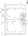
- FIG. 1 is a cutaway perspective view of a radial impeller system 10 being utilized with a container 12 suitable for use with an embodiment.
- the radial impeller system 10 includes an radial impeller assembly 14.
- the radial impeller assembly 14 includes a radial impeller 16 and a shaft 18.
- the radial impeller system 10 further includes a gearbox 20, and motor 22. Alternatively, the motor 22 may directly rotate the shaft 18 and the gearbox 20 may be omitted.
- the container 12 includes any suitable container or vessel such as, for example, a barrel, a tank, a trough, a pipe, or the like.
- the motor 22 is configured to rotate the shaft 18.
- the shaft 18 is configured for insertion down through a port 24 in a lid 26 of the container 12. Rotation of the shaft 18 urges the radial impeller assembly 14 to rotate. More particularly, the radial impeller 16 is urged to rotate.
- the radial impeller 16 includes a plurality of blades 30 mounted to a hub 32 via a disk 28. As shown more clearly in FIG. 2 , the radial impeller 16 may include six blades 30 and in other examples, the radial impeller 16 may include two, three, four, or more blades 30.
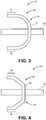
- the blades 30 may include a profile 34 that is generally "C" shaped when viewed edge-on.
- each blade includes a root 36 secured to the disk 28 and an edge or tip 38 that is distal from the hub 32.
- the general "C" shape of the profile 34 may be curved (as shown in FIG. 3 ) and/or may include planar portions connected to each other along one or more angles (as shown in FIG. 4 ).
- the blades 30 may include horizontal extensions 40 extending from an upper and/or lower portion of the profile 34.
- the horizontal extension 40 at the upper portion of the profile 34 extends along a plane that is parallel to a plane defined by the disk 28.
- the horizontal extension 40 at the lower portion of the profile 34 extends along a plane that is parallel to the plane defined by the disk 28. Without being bound by any particular scientific theorem, it appears the horizontal extensions 40 reduce turbulence and/or cavitation of the fluid flowing around the blade 30 and therefore cause a corresponding reduction in wear. This reduced wear is particularly evident by comparing FIG. 5 to FIGS. 6 and 7 .
- a fluid fills the container 12 to the level shown by the wavy line 42.
- the container 12 may be equipped with one or more vanes or baffles 44 which extend radially from the walls of the container 12.
- the principal direction of the flow is radial; that is, radiating outward in a horizontal plane that coincides with a plane of the radial impeller 16.
- Flow is redirected by the container 12 and/or baffles 44.
- flow is redirected upwards along sidewalls of the container and generally proceeds in a toroidal flow as shown by the loops 46 show the direction of the total flow in the container 12, which is axially downward in the direction of pumping by the radial impeller 16 and then upward along the wall of the container 12.
- This toroidal flow may be facilitated by the baffle 44 that acts to constrain circular flow about the container 12.
- the principal radial component of the flow is obtained due to the action of the radial impeller 16.
- the container 12 diameter T is approximately three times the diameter D of the radial impeller 16.
- the diameter D of the radial impeller 16 is defined as the diameter of the circle encompassed by the outer edge of the respective tips 38 of the blades 30. This is the D/T ratio.
- a ratio of 1/3 is typical for mixing devices such as the radial impeller system 10, although this can range between 1/5 and 3/5. The ratio used does not substantially affect the flow pattern inasmuch as the impeller pumps the fluid in a substantially radial direction.
- FIG. 2 is a top view of the radial impeller 16 showing in accordance with an embodiment.
- the radial impeller 16 includes six of the blades 30 that are generally aligned radially with respect to the hub 32. In the particular example shown, about 30% of each of the blades 30 overlap and are affixed to the disk 28. In other examples, the about of overlap may range from about 10% to about 100% overlap.
- Rotation of the radial impeller 16 urges fluid that is proximal to the hub 32 to flow radially out from the hub 32 and toward the respective tips 38 of the blades 30.
- a circular movement of the fluid is imparted as well.
- this circular flow may advantageous and the baffle 44 shown in FIG. 1 may be omitted.
- the baffle 44 or baffles 44 may be included.
- the blades 30 are aligned with radial lines extending from a center point at the hub 32 of the radial impeller 16.
- the blades 30 may be angled at any suitable angle. More particularly, the blades 30 may include a forward or back sweep of ⁇ 1° to 15°.
- FIGS. 3 and 4 are end views of the blade 30 with different profiles 34 suitable for the radial impeller 16 in accordance with an embodiment.
- the profiles 34 include the horizontal extensions 40 and a body portion 50.
- the body portion 50 is substantially curved.
- the body portion 50 includes substantially planar segments connected along angular joints.
- the horizontal extensions 40 facilitate a reduction in wear of the radial impeller 16.
- FIG. 5 is a perspective view showing a wear pattern 60 in a prior art radial impeller.
- the prior art radial impeller has been coated with several layers of different colored paint or similar coatings. These layers may include the same or different wear properties and the wear properties of the coatings may be predetermined in order to evaluate the wear characteristics of the various impeller conformations.
- the wear pattern 60 includes a relatively large portion of the prior art radial impeller (in comparison to the radial impeller 16 shown in FIG. 6 and 7 ) has sustained sufficient wear that several coating layers have been removed. More particularly, the wear pattern 60 includes a plurality of extreme wear zones 62 that has penetrated five or more layers.
- FIG. 6 is a perspective view showing a wear pattern 70 in the radial impeller 16 in accordance with an embodiment of the blade shown in FIG. 3 .
- the size and severity of the wear pattern 70 on the radial impeller 16 is reduced as compared to the wear pattern 60 in the prior art radial impeller 16 shown in FIG. 5 and given the same operating conditions.
- the wear pattern 70 is less than 30% the size of the wear pattern 60 and does not include any zones of extreme wear.
- FIG. 7 is a perspective view showing the wear pattern 70 in the radial impeller 16 in accordance with an embodiment of the blade shown in FIG. 4 .
- the size and severity of the wear pattern 70 on the radial impeller 16 is reduced as compared to the wear pattern 60 in the prior art radial impeller 16 shown in FIG. 5 and given the same operating conditions.
- the wear pattern 70 is less than 30% the size of the wear pattern 60 and does not include any zones of extreme wear.
- FIG. 8 is a graph showing a comparison of the gassed power response versus dimensionless gas rate of the radial impeller in accordance with the embodiment verses a prior art impeller.
- the term, 'gassed' refers to a gas such as air incorporated into a mixture.
- the radial impeller 16 has less of a reduction in power draw as it is gassed.
- This improved power response of the radial impeller 16 facilitates operation at a slower speed, relative to conventional impeller, to target the same power input as imparted by conventional impellers while still dispersing the gas in the same manner.
- slower rotation corresponds to a lower tip speed (all other factors being equal) and blade wear is a function of tip speed cubed.
Landscapes
- Engineering & Computer Science (AREA)
- Mechanical Engineering (AREA)
- General Engineering & Computer Science (AREA)
- Chemical & Material Sciences (AREA)
- Chemical Kinetics & Catalysis (AREA)
- Physics & Mathematics (AREA)
- Geometry (AREA)
- Organic Chemistry (AREA)
- Mixers Of The Rotary Stirring Type (AREA)
- Structures Of Non-Positive Displacement Pumps (AREA)
Applications Claiming Priority (1)
| Application Number | Priority Date | Filing Date | Title |
|---|---|---|---|
| US15/164,349 US10618018B2 (en) | 2016-05-25 | 2016-05-25 | Low wear radial flow impeller device and system |
Publications (2)
| Publication Number | Publication Date |
|---|---|
| EP3249237A1 true EP3249237A1 (de) | 2017-11-29 |
| EP3249237B1 EP3249237B1 (de) | 2021-02-17 |
Family
ID=58772391
Family Applications (1)
| Application Number | Title | Priority Date | Filing Date |
|---|---|---|---|
| EP17172087.3A Active EP3249237B1 (de) | 2016-05-25 | 2017-05-19 | Radiallüfterrad mit geringem verschleiss und mischsystem damit |
Country Status (7)
| Country | Link |
|---|---|
| US (1) | US10618018B2 (de) |
| EP (1) | EP3249237B1 (de) |
| CN (1) | CN107433154A (de) |
| AU (1) | AU2017202803B2 (de) |
| BR (1) | BR102017010999B1 (de) |
| CA (1) | CA2965801C (de) |
| SG (1) | SG10201704040TA (de) |
Cited By (1)
| Publication number | Priority date | Publication date | Assignee | Title |
|---|---|---|---|---|
| WO2020120251A3 (en) * | 2018-12-14 | 2020-07-23 | Global Life Sciences Solutions Usa Llc | Impeller and sparger assemblies for a bioprocessing system |
Families Citing this family (2)
| Publication number | Priority date | Publication date | Assignee | Title |
|---|---|---|---|---|
| DE102020127989A1 (de) | 2020-10-23 | 2022-04-28 | Uutechnic Oy | Begasungsturbine |
| CN119664714B (zh) * | 2024-12-20 | 2025-12-26 | 利欧集团泵业科技有限公司 | 一种具有汽泡抑制作用的两级诱导轮结构及其设计方法 |
Citations (4)
| Publication number | Priority date | Publication date | Assignee | Title |
|---|---|---|---|---|
| US5198156A (en) * | 1986-02-17 | 1993-03-30 | Imperial Chemical Industries Plc | Agitators |
| US5813837A (en) * | 1995-11-01 | 1998-09-29 | Shinko Pantec Kabushiki Kaisha | Axial-flow impeller for mixing liquids |
| US20090231952A1 (en) * | 2007-12-21 | 2009-09-17 | Higbee Robert W | Gas foil impeller |
| US20140071788A1 (en) * | 2011-11-24 | 2014-03-13 | Li Wang | Mixing impeller having channel-shaped vanes |
Family Cites Families (12)
| Publication number | Priority date | Publication date | Assignee | Title |
|---|---|---|---|---|
| US4305673A (en) | 1980-03-25 | 1981-12-15 | General Signal Corporation | High efficiency mixing impeller |
| SE461444B (sv) | 1985-11-21 | 1990-02-19 | Boerje Skaanberg | Impellerapparat foer omroerning av vaetska under dispergering av gas daeri |
| US6190033B1 (en) | 1999-04-09 | 2001-02-20 | Pfaulder, Inc. | High gas dispersion efficiency glass coated impeller |
| US6955461B2 (en) * | 2003-01-24 | 2005-10-18 | Dow Global Technologies, Inc. | Tickler for slurry reactors and tanks |
| EP1776999A1 (de) | 2005-10-21 | 2007-04-25 | Abb Research Ltd. | Ein Mischer |
| CN2907854Y (zh) * | 2006-05-19 | 2007-06-06 | 李丰刚 | 自动搅药装置 |
| US20080199321A1 (en) | 2007-02-16 | 2008-08-21 | Spx Corporation | Parabolic radial flow impeller with tilted or offset blades |
| CN201231143Y (zh) * | 2007-11-29 | 2009-05-06 | 东华大学 | 高效搅拌桨 |
| TWI480249B (zh) * | 2010-11-01 | 2015-04-11 | Avanstrate Inc | Glass substrate manufacturing method and stirring device |
| CN203227432U (zh) * | 2013-04-19 | 2013-10-09 | 特浦朗克化工(营口)股份有限公司 | 一种新型调和罐 |
| CN104279183A (zh) * | 2014-10-29 | 2015-01-14 | 湖南天雁机械有限责任公司 | 径流和斜流相结合的涡轮增压器压气机叶轮 |
| US9683208B2 (en) * | 2015-07-31 | 2017-06-20 | Ernest Louis Stadler | Horizontal single use pressurizable modular multi-agitator microbial fermentator |
-
2016
- 2016-05-25 US US15/164,349 patent/US10618018B2/en active Active
-
2017
- 2017-04-27 AU AU2017202803A patent/AU2017202803B2/en active Active
- 2017-04-28 CA CA2965801A patent/CA2965801C/en active Active
- 2017-05-17 SG SG10201704040TA patent/SG10201704040TA/en unknown
- 2017-05-19 EP EP17172087.3A patent/EP3249237B1/de active Active
- 2017-05-23 CN CN201710370558.2A patent/CN107433154A/zh active Pending
- 2017-05-25 BR BR102017010999-2A patent/BR102017010999B1/pt active IP Right Grant
Patent Citations (4)
| Publication number | Priority date | Publication date | Assignee | Title |
|---|---|---|---|---|
| US5198156A (en) * | 1986-02-17 | 1993-03-30 | Imperial Chemical Industries Plc | Agitators |
| US5813837A (en) * | 1995-11-01 | 1998-09-29 | Shinko Pantec Kabushiki Kaisha | Axial-flow impeller for mixing liquids |
| US20090231952A1 (en) * | 2007-12-21 | 2009-09-17 | Higbee Robert W | Gas foil impeller |
| US20140071788A1 (en) * | 2011-11-24 | 2014-03-13 | Li Wang | Mixing impeller having channel-shaped vanes |
Non-Patent Citations (1)
| Title |
|---|
| YUYUN BAO ET AL: "Influence of the Top Impeller Diameter on the Gas Dispersion in a Sparged Multi-impeller Stirred Tank", INDUSTRIAL & ENGINEERING CHEMISTRY RESEARCH., vol. 51, no. 38, 29 August 2012 (2012-08-29), US, pages 12411 - 12420, XP055404852, ISSN: 0888-5885, DOI: 10.1021/ie301150b * |
Cited By (3)
| Publication number | Priority date | Publication date | Assignee | Title |
|---|---|---|---|---|
| WO2020120251A3 (en) * | 2018-12-14 | 2020-07-23 | Global Life Sciences Solutions Usa Llc | Impeller and sparger assemblies for a bioprocessing system |
| CN117511705A (zh) * | 2018-12-14 | 2024-02-06 | 环球生命科技咨询美国有限责任公司 | 用于生物处理系统的叶轮和喷射器组件 |
| US12589366B2 (en) | 2018-12-14 | 2026-03-31 | Global Life Sciences Solutions Usa Llc | Impeller and sparger assemblies for a bioprocessing system |
Also Published As
| Publication number | Publication date |
|---|---|
| US20170343005A1 (en) | 2017-11-30 |
| BR102017010999B1 (pt) | 2023-04-18 |
| EP3249237B1 (de) | 2021-02-17 |
| CN107433154A (zh) | 2017-12-05 |
| BR102017010999A2 (pt) | 2018-05-02 |
| US10618018B2 (en) | 2020-04-14 |
| SG10201704040TA (en) | 2017-12-28 |
| BR102017010999A8 (pt) | 2022-07-26 |
| AU2017202803A1 (en) | 2017-12-14 |
| CA2965801C (en) | 2023-08-15 |
| AU2017202803B2 (en) | 2021-08-05 |
| CA2965801A1 (en) | 2017-11-25 |
Similar Documents
| Publication | Publication Date | Title |
|---|---|---|
| US5198156A (en) | Agitators | |
| US8220986B2 (en) | High efficiency mixer-impeller | |
| US7172337B2 (en) | Low shear impeller | |
| CN103962040B (zh) | 搅拌装置、搅拌系统及用于处理材料的方法 | |
| CN103958041B (zh) | 具有槽形叶片的搅拌叶轮 | |
| CA2965801C (en) | Low wear radial flow impeller device and system | |
| CN109999691B (zh) | 搅拌机构设备 | |
| US8876369B1 (en) | Apparatus for mixing liquids and/or solids with liquids | |
| KR102275224B1 (ko) | 교반 날개 및 교반 장치 | |
| JP7219831B2 (ja) | 攪拌装置 | |
| JPWO2024024262A5 (de) | ||
| EP3088075B1 (de) | Rührblatt und rührvorrichtung | |
| AU2017203150B2 (en) | Trimable impeller device and system | |
| JP5597315B1 (ja) | 攪拌装置 | |
| JP5702598B2 (ja) | 攪拌用回転体および攪拌装置 | |
| EP4400206A1 (de) | Gerührter tank mit verbesserter homogenität der blasenverteilung und verfahren dafür | |
| Frasano | Select the right impeller | |
| WO2025265039A1 (en) | Blade for impeller and methods of making and using the same | |
| BR102017011015B1 (pt) | Impulsor; conjunto de impulsor e sistema de mistura |
Legal Events
| Date | Code | Title | Description |
|---|---|---|---|
| PUAI | Public reference made under article 153(3) epc to a published international application that has entered the european phase |
Free format text: ORIGINAL CODE: 0009012 |
|
| STAA | Information on the status of an ep patent application or granted ep patent |
Free format text: STATUS: THE APPLICATION HAS BEEN PUBLISHED |
|
| AK | Designated contracting states |
Kind code of ref document: A1 Designated state(s): AL AT BE BG CH CY CZ DE DK EE ES FI FR GB GR HR HU IE IS IT LI LT LU LV MC MK MT NL NO PL PT RO RS SE SI SK SM TR |
|
| AX | Request for extension of the european patent |
Extension state: BA ME |
|
| STAA | Information on the status of an ep patent application or granted ep patent |
Free format text: STATUS: REQUEST FOR EXAMINATION WAS MADE |
|
| 17P | Request for examination filed |
Effective date: 20180517 |
|
| RBV | Designated contracting states (corrected) |
Designated state(s): AL AT BE BG CH CY CZ DE DK EE ES FI FR GB GR HR HU IE IS IT LI LT LU LV MC MK MT NL NO PL PT RO RS SE SI SK SM TR |
|
| STAA | Information on the status of an ep patent application or granted ep patent |
Free format text: STATUS: EXAMINATION IS IN PROGRESS |
|
| 17Q | First examination report despatched |
Effective date: 20181030 |
|
| GRAP | Despatch of communication of intention to grant a patent |
Free format text: ORIGINAL CODE: EPIDOSNIGR1 |
|
| STAA | Information on the status of an ep patent application or granted ep patent |
Free format text: STATUS: GRANT OF PATENT IS INTENDED |
|
| INTG | Intention to grant announced |
Effective date: 20201117 |
|
| GRAS | Grant fee paid |
Free format text: ORIGINAL CODE: EPIDOSNIGR3 |
|
| GRAA | (expected) grant |
Free format text: ORIGINAL CODE: 0009210 |
|
| STAA | Information on the status of an ep patent application or granted ep patent |
Free format text: STATUS: THE PATENT HAS BEEN GRANTED |
|
| AK | Designated contracting states |
Kind code of ref document: B1 Designated state(s): AL AT BE BG CH CY CZ DE DK EE ES FI FR GB GR HR HU IE IS IT LI LT LU LV MC MK MT NL NO PL PT RO RS SE SI SK SM TR |
|
| REG | Reference to a national code |
Ref country code: GB Ref legal event code: FG4D |
|
| REG | Reference to a national code |
Ref country code: CH Ref legal event code: EP |
|
| REG | Reference to a national code |
Ref country code: DE Ref legal event code: R096 Ref document number: 602017032508 Country of ref document: DE |
|
| REG | Reference to a national code |
Ref country code: AT Ref legal event code: REF Ref document number: 1361847 Country of ref document: AT Kind code of ref document: T Effective date: 20210315 |
|
| REG | Reference to a national code |
Ref country code: IE Ref legal event code: FG4D |
|
| REG | Reference to a national code |
Ref country code: SE Ref legal event code: TRGR |
|
| REG | Reference to a national code |
Ref country code: LT Ref legal event code: MG9D |
|
| REG | Reference to a national code |
Ref country code: NL Ref legal event code: MP Effective date: 20210217 |
|
| PG25 | Lapsed in a contracting state [announced via postgrant information from national office to epo] |
Ref country code: HR Free format text: LAPSE BECAUSE OF FAILURE TO SUBMIT A TRANSLATION OF THE DESCRIPTION OR TO PAY THE FEE WITHIN THE PRESCRIBED TIME-LIMIT Effective date: 20210217 Ref country code: FI Free format text: LAPSE BECAUSE OF FAILURE TO SUBMIT A TRANSLATION OF THE DESCRIPTION OR TO PAY THE FEE WITHIN THE PRESCRIBED TIME-LIMIT Effective date: 20210217 Ref country code: GR Free format text: LAPSE BECAUSE OF FAILURE TO SUBMIT A TRANSLATION OF THE DESCRIPTION OR TO PAY THE FEE WITHIN THE PRESCRIBED TIME-LIMIT Effective date: 20210518 Ref country code: PT Free format text: LAPSE BECAUSE OF FAILURE TO SUBMIT A TRANSLATION OF THE DESCRIPTION OR TO PAY THE FEE WITHIN THE PRESCRIBED TIME-LIMIT Effective date: 20210617 Ref country code: NO Free format text: LAPSE BECAUSE OF FAILURE TO SUBMIT A TRANSLATION OF THE DESCRIPTION OR TO PAY THE FEE WITHIN THE PRESCRIBED TIME-LIMIT Effective date: 20210517 Ref country code: BG Free format text: LAPSE BECAUSE OF FAILURE TO SUBMIT A TRANSLATION OF THE DESCRIPTION OR TO PAY THE FEE WITHIN THE PRESCRIBED TIME-LIMIT Effective date: 20210517 Ref country code: LT Free format text: LAPSE BECAUSE OF FAILURE TO SUBMIT A TRANSLATION OF THE DESCRIPTION OR TO PAY THE FEE WITHIN THE PRESCRIBED TIME-LIMIT Effective date: 20210217 |
|
| REG | Reference to a national code |
Ref country code: AT Ref legal event code: MK05 Ref document number: 1361847 Country of ref document: AT Kind code of ref document: T Effective date: 20210217 |
|
| PG25 | Lapsed in a contracting state [announced via postgrant information from national office to epo] |
Ref country code: RS Free format text: LAPSE BECAUSE OF FAILURE TO SUBMIT A TRANSLATION OF THE DESCRIPTION OR TO PAY THE FEE WITHIN THE PRESCRIBED TIME-LIMIT Effective date: 20210217 Ref country code: LV Free format text: LAPSE BECAUSE OF FAILURE TO SUBMIT A TRANSLATION OF THE DESCRIPTION OR TO PAY THE FEE WITHIN THE PRESCRIBED TIME-LIMIT Effective date: 20210217 Ref country code: NL Free format text: LAPSE BECAUSE OF FAILURE TO SUBMIT A TRANSLATION OF THE DESCRIPTION OR TO PAY THE FEE WITHIN THE PRESCRIBED TIME-LIMIT Effective date: 20210217 Ref country code: PL Free format text: LAPSE BECAUSE OF FAILURE TO SUBMIT A TRANSLATION OF THE DESCRIPTION OR TO PAY THE FEE WITHIN THE PRESCRIBED TIME-LIMIT Effective date: 20210217 |
|
| PG25 | Lapsed in a contracting state [announced via postgrant information from national office to epo] |
Ref country code: IS Free format text: LAPSE BECAUSE OF FAILURE TO SUBMIT A TRANSLATION OF THE DESCRIPTION OR TO PAY THE FEE WITHIN THE PRESCRIBED TIME-LIMIT Effective date: 20210617 |
|
| PG25 | Lapsed in a contracting state [announced via postgrant information from national office to epo] |
Ref country code: AT Free format text: LAPSE BECAUSE OF FAILURE TO SUBMIT A TRANSLATION OF THE DESCRIPTION OR TO PAY THE FEE WITHIN THE PRESCRIBED TIME-LIMIT Effective date: 20210217 Ref country code: SM Free format text: LAPSE BECAUSE OF FAILURE TO SUBMIT A TRANSLATION OF THE DESCRIPTION OR TO PAY THE FEE WITHIN THE PRESCRIBED TIME-LIMIT Effective date: 20210217 Ref country code: EE Free format text: LAPSE BECAUSE OF FAILURE TO SUBMIT A TRANSLATION OF THE DESCRIPTION OR TO PAY THE FEE WITHIN THE PRESCRIBED TIME-LIMIT Effective date: 20210217 Ref country code: CZ Free format text: LAPSE BECAUSE OF FAILURE TO SUBMIT A TRANSLATION OF THE DESCRIPTION OR TO PAY THE FEE WITHIN THE PRESCRIBED TIME-LIMIT Effective date: 20210217 |
|
| REG | Reference to a national code |
Ref country code: DE Ref legal event code: R097 Ref document number: 602017032508 Country of ref document: DE |
|
| PG25 | Lapsed in a contracting state [announced via postgrant information from national office to epo] |
Ref country code: DK Free format text: LAPSE BECAUSE OF FAILURE TO SUBMIT A TRANSLATION OF THE DESCRIPTION OR TO PAY THE FEE WITHIN THE PRESCRIBED TIME-LIMIT Effective date: 20210217 Ref country code: RO Free format text: LAPSE BECAUSE OF FAILURE TO SUBMIT A TRANSLATION OF THE DESCRIPTION OR TO PAY THE FEE WITHIN THE PRESCRIBED TIME-LIMIT Effective date: 20210217 Ref country code: SK Free format text: LAPSE BECAUSE OF FAILURE TO SUBMIT A TRANSLATION OF THE DESCRIPTION OR TO PAY THE FEE WITHIN THE PRESCRIBED TIME-LIMIT Effective date: 20210217 |
|
| PLBE | No opposition filed within time limit |
Free format text: ORIGINAL CODE: 0009261 |
|
| STAA | Information on the status of an ep patent application or granted ep patent |
Free format text: STATUS: NO OPPOSITION FILED WITHIN TIME LIMIT |
|
| REG | Reference to a national code |
Ref country code: CH Ref legal event code: PL |
|
| 26N | No opposition filed |
Effective date: 20211118 |
|
| PG25 | Lapsed in a contracting state [announced via postgrant information from national office to epo] |
Ref country code: ES Free format text: LAPSE BECAUSE OF FAILURE TO SUBMIT A TRANSLATION OF THE DESCRIPTION OR TO PAY THE FEE WITHIN THE PRESCRIBED TIME-LIMIT Effective date: 20210217 Ref country code: MC Free format text: LAPSE BECAUSE OF FAILURE TO SUBMIT A TRANSLATION OF THE DESCRIPTION OR TO PAY THE FEE WITHIN THE PRESCRIBED TIME-LIMIT Effective date: 20210217 Ref country code: LI Free format text: LAPSE BECAUSE OF NON-PAYMENT OF DUE FEES Effective date: 20210531 Ref country code: LU Free format text: LAPSE BECAUSE OF NON-PAYMENT OF DUE FEES Effective date: 20210519 Ref country code: CH Free format text: LAPSE BECAUSE OF NON-PAYMENT OF DUE FEES Effective date: 20210531 Ref country code: AL Free format text: LAPSE BECAUSE OF FAILURE TO SUBMIT A TRANSLATION OF THE DESCRIPTION OR TO PAY THE FEE WITHIN THE PRESCRIBED TIME-LIMIT Effective date: 20210217 |
|
| REG | Reference to a national code |
Ref country code: BE Ref legal event code: MM Effective date: 20210531 |
|
| PG25 | Lapsed in a contracting state [announced via postgrant information from national office to epo] |
Ref country code: SI Free format text: LAPSE BECAUSE OF FAILURE TO SUBMIT A TRANSLATION OF THE DESCRIPTION OR TO PAY THE FEE WITHIN THE PRESCRIBED TIME-LIMIT Effective date: 20210217 |
|
| PG25 | Lapsed in a contracting state [announced via postgrant information from national office to epo] |
Ref country code: IE Free format text: LAPSE BECAUSE OF NON-PAYMENT OF DUE FEES Effective date: 20210519 |
|
| PG25 | Lapsed in a contracting state [announced via postgrant information from national office to epo] |
Ref country code: IS Free format text: LAPSE BECAUSE OF FAILURE TO SUBMIT A TRANSLATION OF THE DESCRIPTION OR TO PAY THE FEE WITHIN THE PRESCRIBED TIME-LIMIT Effective date: 20210617 |
|
| PG25 | Lapsed in a contracting state [announced via postgrant information from national office to epo] |
Ref country code: BE Free format text: LAPSE BECAUSE OF NON-PAYMENT OF DUE FEES Effective date: 20210531 |
|
| PG25 | Lapsed in a contracting state [announced via postgrant information from national office to epo] |
Ref country code: HU Free format text: LAPSE BECAUSE OF FAILURE TO SUBMIT A TRANSLATION OF THE DESCRIPTION OR TO PAY THE FEE WITHIN THE PRESCRIBED TIME-LIMIT; INVALID AB INITIO Effective date: 20170519 |
|
| PG25 | Lapsed in a contracting state [announced via postgrant information from national office to epo] |
Ref country code: CY Free format text: LAPSE BECAUSE OF FAILURE TO SUBMIT A TRANSLATION OF THE DESCRIPTION OR TO PAY THE FEE WITHIN THE PRESCRIBED TIME-LIMIT Effective date: 20210217 |
|
| PG25 | Lapsed in a contracting state [announced via postgrant information from national office to epo] |
Ref country code: MK Free format text: LAPSE BECAUSE OF FAILURE TO SUBMIT A TRANSLATION OF THE DESCRIPTION OR TO PAY THE FEE WITHIN THE PRESCRIBED TIME-LIMIT Effective date: 20210217 |
|
| PGFP | Annual fee paid to national office [announced via postgrant information from national office to epo] |
Ref country code: GB Payment date: 20240527 Year of fee payment: 8 |
|
| PGFP | Annual fee paid to national office [announced via postgrant information from national office to epo] |
Ref country code: FR Payment date: 20240527 Year of fee payment: 8 |
|
| PGFP | Annual fee paid to national office [announced via postgrant information from national office to epo] |
Ref country code: SE Payment date: 20240527 Year of fee payment: 8 |
|
| PG25 | Lapsed in a contracting state [announced via postgrant information from national office to epo] |
Ref country code: MT Free format text: LAPSE BECAUSE OF FAILURE TO SUBMIT A TRANSLATION OF THE DESCRIPTION OR TO PAY THE FEE WITHIN THE PRESCRIBED TIME-LIMIT Effective date: 20210217 |
|
| PGFP | Annual fee paid to national office [announced via postgrant information from national office to epo] |
Ref country code: IT Payment date: 20240521 Year of fee payment: 8 |
|
| PGFP | Annual fee paid to national office [announced via postgrant information from national office to epo] |
Ref country code: DE Payment date: 20250529 Year of fee payment: 9 |
|
| PG25 | Lapsed in a contracting state [announced via postgrant information from national office to epo] |
Ref country code: TR Free format text: LAPSE BECAUSE OF FAILURE TO SUBMIT A TRANSLATION OF THE DESCRIPTION OR TO PAY THE FEE WITHIN THE PRESCRIBED TIME-LIMIT Effective date: 20210217 |
|
| PG25 | Lapsed in a contracting state [announced via postgrant information from national office to epo] |
Ref country code: SE Free format text: LAPSE BECAUSE OF NON-PAYMENT OF DUE FEES Effective date: 20250520 |
|
| REG | Reference to a national code |
Ref country code: SE Ref legal event code: EUG |
|
| GBPC | Gb: european patent ceased through non-payment of renewal fee |
Effective date: 20250519 |
|
| PG25 | Lapsed in a contracting state [announced via postgrant information from national office to epo] |
Ref country code: GB Free format text: LAPSE BECAUSE OF NON-PAYMENT OF DUE FEES Effective date: 20250519 |
|
| PG25 | Lapsed in a contracting state [announced via postgrant information from national office to epo] |
Ref country code: IT Free format text: LAPSE BECAUSE OF NON-PAYMENT OF DUE FEES Effective date: 20250519 |
|
| PG25 | Lapsed in a contracting state [announced via postgrant information from national office to epo] |
Ref country code: FR Free format text: LAPSE BECAUSE OF NON-PAYMENT OF DUE FEES Effective date: 20250531 |