EP3249234A1 - Turbocharger with two-stage series compressor driven by exhaust gas-driven turbine and electric motor - Google Patents
Turbocharger with two-stage series compressor driven by exhaust gas-driven turbine and electric motor Download PDFInfo
- Publication number
- EP3249234A1 EP3249234A1 EP17167437.7A EP17167437A EP3249234A1 EP 3249234 A1 EP3249234 A1 EP 3249234A1 EP 17167437 A EP17167437 A EP 17167437A EP 3249234 A1 EP3249234 A1 EP 3249234A1
- Authority
- EP
- European Patent Office
- Prior art keywords
- impeller
- compressor
- housing
- turbocharger
- motor
- Prior art date
- Legal status (The legal status is an assumption and is not a legal conclusion. Google has not performed a legal analysis and makes no representation as to the accuracy of the status listed.)
- Granted
Links
Images



Classifications
-
- F—MECHANICAL ENGINEERING; LIGHTING; HEATING; WEAPONS; BLASTING
- F02—COMBUSTION ENGINES; HOT-GAS OR COMBUSTION-PRODUCT ENGINE PLANTS
- F02B—INTERNAL-COMBUSTION PISTON ENGINES; COMBUSTION ENGINES IN GENERAL
- F02B37/00—Engines characterised by provision of pumps driven at least for part of the time by exhaust
- F02B37/04—Engines with exhaust drive and other drive of pumps, e.g. with exhaust-driven pump and mechanically-driven second pump
- F02B37/10—Engines with exhaust drive and other drive of pumps, e.g. with exhaust-driven pump and mechanically-driven second pump at least one pump being alternatively or simultaneously driven by exhaust and other drive, e.g. by pressurised fluid from a reservoir or an engine-driven pump
-
- F—MECHANICAL ENGINEERING; LIGHTING; HEATING; WEAPONS; BLASTING
- F02—COMBUSTION ENGINES; HOT-GAS OR COMBUSTION-PRODUCT ENGINE PLANTS
- F02B—INTERNAL-COMBUSTION PISTON ENGINES; COMBUSTION ENGINES IN GENERAL
- F02B37/00—Engines characterised by provision of pumps driven at least for part of the time by exhaust
- F02B37/013—Engines characterised by provision of pumps driven at least for part of the time by exhaust with exhaust-driven pumps arranged in series
-
- F—MECHANICAL ENGINEERING; LIGHTING; HEATING; WEAPONS; BLASTING
- F02—COMBUSTION ENGINES; HOT-GAS OR COMBUSTION-PRODUCT ENGINE PLANTS
- F02B—INTERNAL-COMBUSTION PISTON ENGINES; COMBUSTION ENGINES IN GENERAL
- F02B37/00—Engines characterised by provision of pumps driven at least for part of the time by exhaust
- F02B37/12—Control of the pumps
- F02B37/22—Control of the pumps by varying cross-section of exhaust passages or air passages, e.g. by throttling turbine inlets or outlets or by varying effective number of guide conduits
-
- F—MECHANICAL ENGINEERING; LIGHTING; HEATING; WEAPONS; BLASTING
- F02—COMBUSTION ENGINES; HOT-GAS OR COMBUSTION-PRODUCT ENGINE PLANTS
- F02B—INTERNAL-COMBUSTION PISTON ENGINES; COMBUSTION ENGINES IN GENERAL
- F02B39/00—Component parts, details, or accessories relating to, driven charging or scavenging pumps, not provided for in groups F02B33/00 - F02B37/00
- F02B39/005—Cooling of pump drives
-
- F—MECHANICAL ENGINEERING; LIGHTING; HEATING; WEAPONS; BLASTING
- F02—COMBUSTION ENGINES; HOT-GAS OR COMBUSTION-PRODUCT ENGINE PLANTS
- F02B—INTERNAL-COMBUSTION PISTON ENGINES; COMBUSTION ENGINES IN GENERAL
- F02B39/00—Component parts, details, or accessories relating to, driven charging or scavenging pumps, not provided for in groups F02B33/00 - F02B37/00
- F02B39/02—Drives of pumps; Varying pump drive gear ratio
- F02B39/08—Non-mechanical drives, e.g. fluid drives having variable gear ratio
- F02B39/10—Non-mechanical drives, e.g. fluid drives having variable gear ratio electric
-
- F—MECHANICAL ENGINEERING; LIGHTING; HEATING; WEAPONS; BLASTING
- F02—COMBUSTION ENGINES; HOT-GAS OR COMBUSTION-PRODUCT ENGINE PLANTS
- F02C—GAS-TURBINE PLANTS; AIR INTAKES FOR JET-PROPULSION PLANTS; CONTROLLING FUEL SUPPLY IN AIR-BREATHING JET-PROPULSION PLANTS
- F02C6/00—Plural gas-turbine plants; Combinations of gas-turbine plants with other apparatus; Adaptations of gas-turbine plants for special use
- F02C6/04—Gas-turbine plants providing heated or pressurised working fluid for other apparatus, e.g. without mechanical power output
- F02C6/10—Gas-turbine plants providing heated or pressurised working fluid for other apparatus, e.g. without mechanical power output supplying working fluid to a user, e.g. a chemical process, which returns working fluid to a turbine of the plant
- F02C6/12—Turbochargers, i.e. plants for augmenting mechanical power output of internal-combustion piston engines by increase of charge pressure
-
- F—MECHANICAL ENGINEERING; LIGHTING; HEATING; WEAPONS; BLASTING
- F04—POSITIVE - DISPLACEMENT MACHINES FOR LIQUIDS; PUMPS FOR LIQUIDS OR ELASTIC FLUIDS
- F04D—NON-POSITIVE-DISPLACEMENT PUMPS
- F04D17/00—Radial-flow pumps, e.g. centrifugal pumps; Helico-centrifugal pumps
- F04D17/08—Centrifugal pumps
- F04D17/10—Centrifugal pumps for compressing or evacuating
- F04D17/12—Multi-stage pumps
-
- F—MECHANICAL ENGINEERING; LIGHTING; HEATING; WEAPONS; BLASTING
- F04—POSITIVE - DISPLACEMENT MACHINES FOR LIQUIDS; PUMPS FOR LIQUIDS OR ELASTIC FLUIDS
- F04D—NON-POSITIVE-DISPLACEMENT PUMPS
- F04D25/00—Pumping installations or systems
- F04D25/02—Units comprising pumps and their driving means
- F04D25/024—Units comprising pumps and their driving means the driving means being assisted by a power recovery turbine
-
- F—MECHANICAL ENGINEERING; LIGHTING; HEATING; WEAPONS; BLASTING
- F04—POSITIVE - DISPLACEMENT MACHINES FOR LIQUIDS; PUMPS FOR LIQUIDS OR ELASTIC FLUIDS
- F04D—NON-POSITIVE-DISPLACEMENT PUMPS
- F04D25/00—Pumping installations or systems
- F04D25/02—Units comprising pumps and their driving means
- F04D25/04—Units comprising pumps and their driving means the pump being fluid-driven
-
- F—MECHANICAL ENGINEERING; LIGHTING; HEATING; WEAPONS; BLASTING
- F04—POSITIVE - DISPLACEMENT MACHINES FOR LIQUIDS; PUMPS FOR LIQUIDS OR ELASTIC FLUIDS
- F04D—NON-POSITIVE-DISPLACEMENT PUMPS
- F04D25/00—Pumping installations or systems
- F04D25/02—Units comprising pumps and their driving means
- F04D25/04—Units comprising pumps and their driving means the pump being fluid-driven
- F04D25/045—Units comprising pumps and their driving means the pump being fluid-driven the pump wheel carrying the fluid driving means, e.g. turbine blades
-
- F—MECHANICAL ENGINEERING; LIGHTING; HEATING; WEAPONS; BLASTING
- F04—POSITIVE - DISPLACEMENT MACHINES FOR LIQUIDS; PUMPS FOR LIQUIDS OR ELASTIC FLUIDS
- F04D—NON-POSITIVE-DISPLACEMENT PUMPS
- F04D25/00—Pumping installations or systems
- F04D25/02—Units comprising pumps and their driving means
- F04D25/06—Units comprising pumps and their driving means the pump being electrically driven
-
- F—MECHANICAL ENGINEERING; LIGHTING; HEATING; WEAPONS; BLASTING
- F04—POSITIVE - DISPLACEMENT MACHINES FOR LIQUIDS; PUMPS FOR LIQUIDS OR ELASTIC FLUIDS
- F04D—NON-POSITIVE-DISPLACEMENT PUMPS
- F04D25/00—Pumping installations or systems
- F04D25/02—Units comprising pumps and their driving means
- F04D25/06—Units comprising pumps and their driving means the pump being electrically driven
- F04D25/0606—Units comprising pumps and their driving means the pump being electrically driven the electric motor being specially adapted for integration in the pump
-
- F—MECHANICAL ENGINEERING; LIGHTING; HEATING; WEAPONS; BLASTING
- F02—COMBUSTION ENGINES; HOT-GAS OR COMBUSTION-PRODUCT ENGINE PLANTS
- F02B—INTERNAL-COMBUSTION PISTON ENGINES; COMBUSTION ENGINES IN GENERAL
- F02B33/00—Engines characterised by provision of pumps for charging or scavenging
- F02B33/32—Engines with pumps other than of reciprocating-piston type
- F02B33/34—Engines with pumps other than of reciprocating-piston type with rotary pumps
- F02B33/40—Engines with pumps other than of reciprocating-piston type with rotary pumps of non-positive-displacement type
-
- F—MECHANICAL ENGINEERING; LIGHTING; HEATING; WEAPONS; BLASTING
- F05—INDEXING SCHEMES RELATING TO ENGINES OR PUMPS IN VARIOUS SUBCLASSES OF CLASSES F01-F04
- F05D—INDEXING SCHEME FOR ASPECTS RELATING TO NON-POSITIVE-DISPLACEMENT MACHINES OR ENGINES, GAS-TURBINES OR JET-PROPULSION PLANTS
- F05D2220/00—Application
- F05D2220/40—Application in turbochargers
-
- F—MECHANICAL ENGINEERING; LIGHTING; HEATING; WEAPONS; BLASTING
- F05—INDEXING SCHEMES RELATING TO ENGINES OR PUMPS IN VARIOUS SUBCLASSES OF CLASSES F01-F04
- F05D—INDEXING SCHEME FOR ASPECTS RELATING TO NON-POSITIVE-DISPLACEMENT MACHINES OR ENGINES, GAS-TURBINES OR JET-PROPULSION PLANTS
- F05D2240/00—Components
- F05D2240/40—Use of a multiplicity of similar components
-
- Y—GENERAL TAGGING OF NEW TECHNOLOGICAL DEVELOPMENTS; GENERAL TAGGING OF CROSS-SECTIONAL TECHNOLOGIES SPANNING OVER SEVERAL SECTIONS OF THE IPC; TECHNICAL SUBJECTS COVERED BY FORMER USPC CROSS-REFERENCE ART COLLECTIONS [XRACs] AND DIGESTS
- Y02—TECHNOLOGIES OR APPLICATIONS FOR MITIGATION OR ADAPTATION AGAINST CLIMATE CHANGE
- Y02T—CLIMATE CHANGE MITIGATION TECHNOLOGIES RELATED TO TRANSPORTATION
- Y02T10/00—Road transport of goods or passengers
- Y02T10/10—Internal combustion engine [ICE] based vehicles
- Y02T10/12—Improving ICE efficiencies
Definitions
- the present disclosure relates to exhaust gas-driven turbochargers that include an electric motor for providing supplementary motive power to the compressor.
- Electric motor-driven turbochargers face compromises in two respects.
- electric motors are mechanically challenged to run at the high speeds that turbochargers typically operate at, and accordingly it is frequently necessary to compromise the aerodynamic design of the compressor so that the compressor can operate at a lower speed in order for the electric motor to be able to survive.
- expensive motor technology is required in order to survive the high speeds.
- the compressor map width which is the difference between the surge line and the choke line, is often a limiting factor in how the engine and turbocharger can be operated.
- this issue is exacerbated because when the motor is powered, the operating pressure ratio at a given engine speed is increased, thus pushing the compressor into surge.
- an e-turbocharger comprises a two-stage series compressor comprising a compressor housing assembly, and a compressor wheel comprising a first impeller and a second impeller that are mounted on a shaft for rotation therewith, the first and second impellers being contained in the compressor housing assembly, the compressor housing assembly defining a first compressor flow path including a first air inlet that leads air into the first impeller, a first volute that collects compressed air that has passed through and been compressed by the first impeller, a second compressor flow path including a second air inlet that leads air into the second impeller, and a second volute that collects compressed air that has passed through and been compressed by the second impeller, and further comprising an interstage duct that connects the first volute to the second air inlet such that air compressed by the first impeller is led by
- the turbocharger further comprises an exhaust gas-driven turbine comprising a turbine housing defining an axial bore therein and a turbine wheel affixed to the shaft and contained in the axial bore of the turbine housing, the turbine housing defining a generally annular chamber arranged to receive exhaust gas, and a nozzle arranged to feed exhaust gas from the chamber generally radially inwardly to the turbine wheel, exhaust gas being discharged from the turbine housing via the axial bore.
- an exhaust gas-driven turbine comprising a turbine housing defining an axial bore therein and a turbine wheel affixed to the shaft and contained in the axial bore of the turbine housing, the turbine housing defining a generally annular chamber arranged to receive exhaust gas, and a nozzle arranged to feed exhaust gas from the chamber generally radially inwardly to the turbine wheel, exhaust gas being discharged from the turbine housing via the axial bore.
- the turbocharger further includes a center housing disposed between the compressor housing assembly and the turbine housing, the center housing containing one or more bearings for the shaft.
- the turbocharger further comprises an electric motor comprising a generally annular motor stator concentrically surrounding a motor rotor, the motor rotor being affixed to the shaft, wherein energizing of the electric motor rotatably drives the motor rotor so as to assist the turbine wheel in rotatably driving the two-stage series compressor.
- a two-stage series compressor can achieve the desired pressure ratios at a lower speed than a single-stage compressor, and accordingly the severe mechanical challenges presented to the electric motor are substantially mitigated.
- the electric motor is disposed between the two-stage series compressor and the exhaust gas-driven turbine.
- the first and second impellers can be arranged in a back-to-back configuration.
- the electric motor includes a motor housing containing the motor stator and the motor rotor, the motor housing defining coolant passageways for circulating a liquid coolant therethrough to cool the electric motor.
- a motor housing containing the motor stator and the motor rotor, the motor housing defining coolant passageways for circulating a liquid coolant therethrough to cool the electric motor.
- an integral one-piece housing member forms both the center housing and the motor housing.
- the compressor housing assembly comprises a first compressor housing containing the first impeller and defining the first volute, and a separately formed second compressor housing containing the second impeller and defining the second volute, and the electric motor is disposed between the first compressor housing and the second compressor housing.
- the electric motor includes a motor housing containing the motor stator and the motor rotor, the motor housing being attached to the first compressor housing and to the second compressor housing.
- the motor housing can define coolant passageways for circulating a liquid coolant therethrough to cool the electric motor.
- first compressor housing and first impeller can be arranged for air to enter the first impeller in a first axial direction
- second compressor housing and second impeller can be arranged for air to enter the second impeller in a second axial direction that is opposite to the first axial direction
- the electric motor is disposed upstream of the two-stage series compressor with respect to an axial direction in which air enters the first impeller.
- the shaft has a portion that extends upstream of the first impeller, and the motor rotor is mounted on said portion of the shaft.
- the exhaust gas-driven turbine in any or all of the embodiments can include a variable-nozzle assembly.
- the variable-nozzle assembly can comprise an array of vanes disposed in the nozzle, the vanes being variable in setting angle for regulating exhaust gas flow into the turbine wheel.
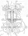
- FIG. 1 illustrates an axial cross-sectional view of a turbocharger 10 in accordance with a first embodiment of the invention.
- the turbocharger includes a compressor 12 rotatably driven by an exhaust gas-driven turbine 22.
- the compressor 12 comprises a compressor wheel 14 affixed to a shaft 18 for rotation therewith.
- the compressor wheel is contained within a compressor housing assembly 16.
- the compressor wheel 14 is a twin-impeller wheel having a first impeller 14a and a second impeller 14b.
- the first and second impellers are arranged in a back-to-back configuration such that air enters the first impeller 14a in an axial first direction (left-to-right in FIG.
- the compressor housing assembly 16 in the illustrated embodiment comprises a first compressor housing 16a containing the first impeller 14a and a second compressor housing 16b containing the second impeller 14b.
- the first compressor housing 16a defines a first air inlet 13a for the first impeller, and also defines a first volute 15a that receives air that has passed through the first impeller and has been pressurized in a first stage of the two-stage compression process provided by the twin-impeller arrangement.
- the compressor housing assembly 16 also defines a first diffuser 17a through which air pressurized by the first impeller 14a is led radially outwardly and is diffused to a lower velocity and higher static pressure before it enters the first volute 17a.
- the compressor housing assembly 16 further defines a second air inlet 13b for the second impeller 14b, a second volute 17b that receives air pressurized by the second impeller, and a second diffuser 17b that diffuses the air pressurized by the second impeller and discharges it into the second volute.
- the compressor housing assembly comprises a separately formed, generally annular disk 16c disposed between the first compressor housing 16a and the second compressor housing 16b. One face of the disk 16c forms a wall of the first diffuser 17a and an opposite face of the disk forms a wall of the second diffuser 17b.
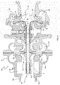
- the compressor housing assembly 16 further includes an interstage duct 16i that leads from the first volute 15a into the second air inlet 13b for the second impeller 14b.
- air that has been partially pressurized by the first impeller 14a is routed from the first volute 15a through the interstage duct 16i into the second air inlet 13b, and is further pressurized by the second impeller in a second stage of the two-stage compression process and is delivered into the second volute 15b for supply to the intake of an internal combustion engine.
- the turbine 22 comprises a turbine wheel 24 contained within a turbine housing 26.
- the turbine housing defines an exhaust gas inlet (not visible in FIG. 1 ) that receives exhaust gas from an internal combustion engine, and a generally annular chamber 28 that receives the exhaust gas from the inlet and distributes the gas around the 360-degree annular chamber.
- the turbine includes a nozzle 30 that leads exhaust gas from the chamber 28 generally radially inwardly into the turbine wheel 24.
- the nozzle 30 is a variable nozzle having an array of variable vanes 32 rotatably mounted to a nozzle ring 34 and caused to pivot about their respective axes by rotation of a unison ring 36 disposed on the opposite side of the nozzle ring from the vanes.
- the turbocharger 10 includes an electric motor 40 disposed between the compressor 12 and the turbine 22.
- the electric motor comprises a motor rotor 42 affixed to the shaft 18 and a generally annular motor stator 44 concentrically surrounding the motor rotor 42.
- the motor stator is housed within a motor housing 46.
- the motor housing defines one or more coolant passages 48 for circulating a liquid coolant to cool the motor.
- the turbocharger 10 also includes a center housing 50 that contains one or more bearings 19 as well as shaft seals for the shaft 18.
- the center housing 50 and the motor housing 46 are both formed by portions of an integral one-piece housing member, and the center housing contains one of two bearings 19 for the shaft.
- the other bearing 19 is held by an assembly comprising a generally annular bearing plate 52 and bearing carrier 54. The assembly of the bearing plate and bearing carrier is fastened between the motor housing 46 and the second compressor housing 16b.
- the electric motor 40 will run on demand where the operating speed and boost pressure are lower than demanded speed/boost. These operating conditions mainly occur at low engine speeds and/or when changing from low load to increased load conditions.
- the electric motor can operate as a generator to produce electrical power that can be used for various purposes in the vehicle, such as helping to charge a battery.
- turbocharger 10' in accordance with a second embodiment of the invention is illustrated in FIG. 3 .
- the turbocharger 10' is similar in many respects to the turbocharger 10 described above, and accordingly the present description will focus primarily on those aspects of the turbocharger 10' that differ from the first embodiment.
- the turbocharger 10' includes a compressor 12 rotatably driven by an exhaust gas-driven turbine 22.
- the compressor 12 comprises a compressor wheel 14 affixed to a shaft 18 for rotation therewith.
- the compressor wheel is contained within a compressor housing assembly 16.
- the compressor wheel 14 is a twin-impeller wheel having a first impeller 14a and a second impeller 14b.
- the first and second impellers are arranged in a back-to-back configuration such that air enters the first impeller 14a in an axial first direction (left-to-right in FIG. 3 ) and air enters the second impeller 14b in a second axial direction (right-to-left in FIG. 3 ) that is opposite to the first direction.
- the compressor housing assembly 16 in the second embodiment comprises a first compressor housing 16a containing the first impeller 14a and a second compressor housing 16b containing the second impeller 14b.
- the first compressor housing 16a defines a first air inlet 13a for the first impeller, and also defines a first volute 15a that receives air that has passed through the first impeller and has been pressurized in a first stage of the two-stage compression process provided by the twin-impeller arrangement.
- the compressor housing assembly 16 also defines a first diffuser 17a through which air pressurized by the first impeller 14a is led radially outwardly and is diffused to a lower velocity and higher static pressure before it enters the first volute 17a.
- the compressor housing assembly 16 further defines a second air inlet 13b for the second impeller 14b, a second volute 17b that receives air pressurized by the second impeller, and a second diffuser 17b that diffuses the air pressurized by the second impeller and discharges it into the second volute.
- the compressor housing assembly 16 further includes an interstage duct that leads from the first volute 17a into the second air inlet 13b for the second impeller 14b.
- air that has been partially pressurized by the first impeller 14a is routed from the first volute 17a through the interstage duct into the second air inlet 13b, and is further pressurized by the second impeller in a second stage of the two-stage compression process and is delivered into the second volute 17b for supply to the intake of an internal combustion engine.
- the turbine 22 comprises a turbine wheel 24 contained within a turbine housing 26.
- the turbine housing defines an exhaust gas inlet (not visible in FIG. 3 ) that receives exhaust gas from an internal combustion engine, and a generally annular chamber 28 that receives the exhaust gas from the inlet and distributes the gas around the 360-degree annular chamber.
- the turbine includes a nozzle 30 that leads exhaust gas from the chamber 28 generally radially inwardly into the turbine wheel 24.
- the nozzle 30 is a variable nozzle having an array of variable vanes 32 rotatably mounted to a nozzle ring 34 and caused to pivot about their respective axes by rotation of a unison ring 36 disposed on the opposite side of the nozzle ring from the vanes.
- the turbocharger 10 includes an electric motor 40 disposed between the first impeller 14a and the second impeller 14b. More particularly, the electric motor comprises a motor housing 46 containing a motor stator 42 that surrounds a motor rotor 44 mounted on the shaft 18. The motor housing 46 is disposed between and fastened to the first compressor housing 16a and the second compressor housing 16b. The second compressor housing 16b is also fastened to one end of a center housing 50 that houses bearings 19 for the shaft 18. The other end of the center housing is fastened to the turbine housing 26.
- the motor housing 46 defines one or more coolant passages 48 for circulating a liquid coolant to cool the motor.
- the first diffuser 17a is bounded between a face of the first compressor housing 16a and an opposing face of the motor housing 46
- the second diffuser 17b is bounded between a face of the second compressor housing 16b and an opposing face of the motor housing 46.
- FIG. 4 illustrates a turbocharger 110 in accordance with a third embodiment of the invention.
- the third embodiment comprises many of the same or similar features as the first and second embodiments, and accordingly the present description will focus primarily on those aspects that differ from the first two embodiments described above.
- the chief difference between the turbocharger 110 and the turbocharger 10 is that the motor 40 of the turbocharger 110 is disposed upstream (with respect to the axial direction in which air enters the first impeller 14a ) of the compressor 12.
- the first compressor housing 16a also serves as a motor housing for containing the motor stator 44.
- the motor rotor 42 is mounted on a portion of the shaft 18 that projects upstream from the first impeller 14a.
- the first inlet 13a for the first impeller 14a may be defined by a separately formed cap or plug 16d that is inserted into the first compressor housing 16a after the motor stator 44 has been installed therein.
- the plug 16d is generally annular or ring-shaped so that air can enter through its central passage in an axial direction and proceed into the first impeller.
- the center housing 50 contains the bearings 19 for the shaft.
- the turbocharger 110 is substantially similar to the turbocharger 10 previously described.
- turbocharger 210 in accordance with a fourth embodiment of the invention is now described with reference to FIG. 5 .
- the turbocharger 210 is similar in many respects to the turbocharger 110, the chief difference being the manner in which air enters the first impeller 14a.
- the compressor housing assembly includes a cover 16d that closes off the front opening in the first compressor housing 16a such that the motor 40 is completely enclosed by the compressor housing assembly. Accordingly, air does not pass through the motor as in the above-described turbocharger 110. Instead, the compressor housing assembly includes a first inlet 13a that receives air via a conduit similar to the way that air is supplied to the second inlet 13b via an interstage duct.
- the turbocharger 210 is substantially similar to the turbocharger 110 previously described.
- the invention is not limited to any particular order of arrangement of the compressor stages, the motor, the bearings, and the turbine along the axial direction.
- the invention encompasses arrangements such as the following non-limiting examples: (1) turbines
- motor turbine
Landscapes
- Engineering & Computer Science (AREA)
- Mechanical Engineering (AREA)
- General Engineering & Computer Science (AREA)
- Chemical & Material Sciences (AREA)
- Combustion & Propulsion (AREA)
- Chemical Kinetics & Catalysis (AREA)
- General Chemical & Material Sciences (AREA)
- Supercharger (AREA)
- Structures Of Non-Positive Displacement Pumps (AREA)
Abstract
Description
- The present disclosure relates to exhaust gas-driven turbochargers that include an electric motor for providing supplementary motive power to the compressor.
- Electric motor-driven turbochargers ("e-turbochargers") face compromises in two respects. First, electric motors are mechanically challenged to run at the high speeds that turbochargers typically operate at, and accordingly it is frequently necessary to compromise the aerodynamic design of the compressor so that the compressor can operate at a lower speed in order for the electric motor to be able to survive. Alternatively, expensive motor technology is required in order to survive the high speeds.
- Second, the compressor map width, which is the difference between the surge line and the choke line, is often a limiting factor in how the engine and turbocharger can be operated. With an e-turbo, this issue is exacerbated because when the motor is powered, the operating pressure ratio at a given engine speed is increased, thus pushing the compressor into surge.
- The present disclosure describes embodiments of an e-turbocharger having features that substantially mitigate the above-noted drawbacks of previous e-turbochargers. In accordance with one embodiment of the invention described herein, an e-turbocharger comprises a two-stage series compressor comprising a compressor housing assembly, and a compressor wheel comprising a first impeller and a second impeller that are mounted on a shaft for rotation therewith, the first and second impellers being contained in the compressor housing assembly, the compressor housing assembly defining a first compressor flow path including a first air inlet that leads air into the first impeller, a first volute that collects compressed air that has passed through and been compressed by the first impeller, a second compressor flow path including a second air inlet that leads air into the second impeller, and a second volute that collects compressed air that has passed through and been compressed by the second impeller, and further comprising an interstage duct that connects the first volute to the second air inlet such that air compressed by the first impeller is led by the interstage duct from the first volute into the second air inlet and is further compressed by the second impeller and delivered into the second volute.
- The turbocharger further comprises an exhaust gas-driven turbine comprising a turbine housing defining an axial bore therein and a turbine wheel affixed to the shaft and contained in the axial bore of the turbine housing, the turbine housing defining a generally annular chamber arranged to receive exhaust gas, and a nozzle arranged to feed exhaust gas from the chamber generally radially inwardly to the turbine wheel, exhaust gas being discharged from the turbine housing via the axial bore.
- The turbocharger further includes a center housing disposed between the compressor housing assembly and the turbine housing, the center housing containing one or more bearings for the shaft. In accordance with the invention, the turbocharger further comprises an electric motor comprising a generally annular motor stator concentrically surrounding a motor rotor, the motor rotor being affixed to the shaft, wherein energizing of the electric motor rotatably drives the motor rotor so as to assist the turbine wheel in rotatably driving the two-stage series compressor.
- In accordance with the invention, coupling a two-stage series compressor with an electric motor mitigates the above-noted drawbacks of previous e-turbochargers that employ single-stage compression. A two-stage series compressor can achieve the desired pressure ratios at a lower speed than a single-stage compressor, and accordingly the severe mechanical challenges presented to the electric motor are substantially mitigated.
- The present disclosure describes various embodiments of the invention. In accordance with one embodiment, the electric motor is disposed between the two-stage series compressor and the exhaust gas-driven turbine. The first and second impellers can be arranged in a back-to-back configuration.
- The electric motor includes a motor housing containing the motor stator and the motor rotor, the motor housing defining coolant passageways for circulating a liquid coolant therethrough to cool the electric motor. In one embodiment an integral one-piece housing member forms both the center housing and the motor housing.
- In another embodiment, the compressor housing assembly comprises a first compressor housing containing the first impeller and defining the first volute, and a separately formed second compressor housing containing the second impeller and defining the second volute, and the electric motor is disposed between the first compressor housing and the second compressor housing. The electric motor includes a motor housing containing the motor stator and the motor rotor, the motor housing being attached to the first compressor housing and to the second compressor housing. The motor housing can define coolant passageways for circulating a liquid coolant therethrough to cool the electric motor.
- In the second embodiment the first compressor housing and first impeller can be arranged for air to enter the first impeller in a first axial direction, and the second compressor housing and second impeller can be arranged for air to enter the second impeller in a second axial direction that is opposite to the first axial direction.
- In a third embodiment the electric motor is disposed upstream of the two-stage series compressor with respect to an axial direction in which air enters the first impeller. The shaft has a portion that extends upstream of the first impeller, and the motor rotor is mounted on said portion of the shaft. There is an annular space disposed between the motor stator and the motor rotor, and said annular space forms part of an air inlet through which air passes in said axial direction to enter the first impeller.
- The exhaust gas-driven turbine in any or all of the embodiments can include a variable-nozzle assembly. As a non-limiting example, the variable-nozzle assembly can comprise an array of vanes disposed in the nozzle, the vanes being variable in setting angle for regulating exhaust gas flow into the turbine wheel.
- Having thus described the present disclosure in general terms, reference will now be made to the accompanying drawings, which are not necessarily drawn to scale, and wherein:
-
FIG. 1 is an axial cross-sectional view of a turbocharger in accordance with a first embodiment of the invention; -
FIG. 2 is an axial cross-sectional view of the turbocharger ofFIG. 1 but taken on a different plane such that the interstage duct can be seen; -
FIG. 3 is an axial cross-sectional view of a turbocharger in accordance with a second embodiment of the invention; -
FIG. 4 is an axial cross-sectional view of a turbocharger in accordance with a third embodiment of the invention; and -
FIG. 5 is an axial cross-sectional view of a turbocharger in accordance with a fourth embodiment of the invention. - The present invention now will be described more fully hereinafter with reference to the accompanying drawings in which some but not all embodiments of the invention are shown. Indeed, aspects of the invention may be embodied in many different forms and should not be construed as limited to the embodiments set forth herein; rather, these embodiments are provided so that this disclosure will satisfy applicable legal requirements. Like numbers refer to like elements throughout.
-
FIG. 1 illustrates an axial cross-sectional view of aturbocharger 10 in accordance with a first embodiment of the invention. The turbocharger includes acompressor 12 rotatably driven by an exhaust gas-driventurbine 22. Thecompressor 12 comprises acompressor wheel 14 affixed to ashaft 18 for rotation therewith. The compressor wheel is contained within acompressor housing assembly 16. Thecompressor wheel 14 is a twin-impeller wheel having afirst impeller 14a and asecond impeller 14b. In the illustrated embodiment, the first and second impellers are arranged in a back-to-back configuration such that air enters thefirst impeller 14a in an axial first direction (left-to-right inFIG. 1 ) and air enters thesecond impeller 14b in a second axial direction (right-to-left inFIG. 1 ) that is opposite to the first direction. The invention, however, is not limited to such a configuration, and the two impellers can instead be oriented in the same manner such that air enters each in the same axial direction. - The
compressor housing assembly 16 in the illustrated embodiment comprises afirst compressor housing 16a containing thefirst impeller 14a and asecond compressor housing 16b containing thesecond impeller 14b. Thefirst compressor housing 16a defines afirst air inlet 13a for the first impeller, and also defines afirst volute 15a that receives air that has passed through the first impeller and has been pressurized in a first stage of the two-stage compression process provided by the twin-impeller arrangement. Thecompressor housing assembly 16 also defines afirst diffuser 17a through which air pressurized by thefirst impeller 14a is led radially outwardly and is diffused to a lower velocity and higher static pressure before it enters thefirst volute 17a. - The
compressor housing assembly 16 further defines asecond air inlet 13b for thesecond impeller 14b, asecond volute 17b that receives air pressurized by the second impeller, and asecond diffuser 17b that diffuses the air pressurized by the second impeller and discharges it into the second volute. In the illustrated embodiment, the compressor housing assembly comprises a separately formed, generallyannular disk 16c disposed between thefirst compressor housing 16a and thesecond compressor housing 16b. One face of thedisk 16c forms a wall of thefirst diffuser 17a and an opposite face of the disk forms a wall of thesecond diffuser 17b. - As shown in
FIG. 2 , thecompressor housing assembly 16 further includes aninterstage duct 16i that leads from thefirst volute 15a into thesecond air inlet 13b for thesecond impeller 14b. Thus, air that has been partially pressurized by thefirst impeller 14a is routed from thefirst volute 15a through theinterstage duct 16i into thesecond air inlet 13b, and is further pressurized by the second impeller in a second stage of the two-stage compression process and is delivered into thesecond volute 15b for supply to the intake of an internal combustion engine. - Turning to the
turbine 22, it comprises aturbine wheel 24 contained within aturbine housing 26. The turbine housing defines an exhaust gas inlet (not visible inFIG. 1 ) that receives exhaust gas from an internal combustion engine, and a generallyannular chamber 28 that receives the exhaust gas from the inlet and distributes the gas around the 360-degree annular chamber. The turbine includes anozzle 30 that leads exhaust gas from thechamber 28 generally radially inwardly into theturbine wheel 24. In the illustrated embodiment, thenozzle 30 is a variable nozzle having an array ofvariable vanes 32 rotatably mounted to anozzle ring 34 and caused to pivot about their respective axes by rotation of aunison ring 36 disposed on the opposite side of the nozzle ring from the vanes. - In the first embodiment of the invention shown in
FIG. 1 , theturbocharger 10 includes anelectric motor 40 disposed between thecompressor 12 and theturbine 22. The electric motor comprises amotor rotor 42 affixed to theshaft 18 and a generallyannular motor stator 44 concentrically surrounding themotor rotor 42. The motor stator is housed within amotor housing 46. The motor housing defines one or morecoolant passages 48 for circulating a liquid coolant to cool the motor. - The
turbocharger 10 also includes acenter housing 50 that contains one ormore bearings 19 as well as shaft seals for theshaft 18. In the embodiment ofFIG. 1 , thecenter housing 50 and themotor housing 46 are both formed by portions of an integral one-piece housing member, and the center housing contains one of twobearings 19 for the shaft. Theother bearing 19 is held by an assembly comprising a generallyannular bearing plate 52 and bearingcarrier 54. The assembly of the bearing plate and bearing carrier is fastened between themotor housing 46 and thesecond compressor housing 16b. - The
electric motor 40 will run on demand where the operating speed and boost pressure are lower than demanded speed/boost. These operating conditions mainly occur at low engine speeds and/or when changing from low load to increased load conditions. When the electric motor is not being powered to supply motive power to theshaft 18 of the turbocharger, the electric motor can operate as a generator to produce electrical power that can be used for various purposes in the vehicle, such as helping to charge a battery. - A turbocharger 10' in accordance with a second embodiment of the invention is illustrated in
FIG. 3 . The turbocharger 10' is similar in many respects to theturbocharger 10 described above, and accordingly the present description will focus primarily on those aspects of the turbocharger 10' that differ from the first embodiment. In accordance with the second embodiment, the turbocharger 10' includes acompressor 12 rotatably driven by an exhaust gas-driventurbine 22. Thecompressor 12 comprises acompressor wheel 14 affixed to ashaft 18 for rotation therewith. The compressor wheel is contained within acompressor housing assembly 16. Thecompressor wheel 14 is a twin-impeller wheel having afirst impeller 14a and asecond impeller 14b. In the illustrated embodiment, the first and second impellers are arranged in a back-to-back configuration such that air enters thefirst impeller 14a in an axial first direction (left-to-right inFIG. 3 ) and air enters thesecond impeller 14b in a second axial direction (right-to-left inFIG. 3 ) that is opposite to the first direction. - The
compressor housing assembly 16 in the second embodiment comprises afirst compressor housing 16a containing thefirst impeller 14a and asecond compressor housing 16b containing thesecond impeller 14b. Thefirst compressor housing 16a defines afirst air inlet 13a for the first impeller, and also defines afirst volute 15a that receives air that has passed through the first impeller and has been pressurized in a first stage of the two-stage compression process provided by the twin-impeller arrangement. Thecompressor housing assembly 16 also defines afirst diffuser 17a through which air pressurized by thefirst impeller 14a is led radially outwardly and is diffused to a lower velocity and higher static pressure before it enters thefirst volute 17a. - The
compressor housing assembly 16 further defines asecond air inlet 13b for thesecond impeller 14b, asecond volute 17b that receives air pressurized by the second impeller, and asecond diffuser 17b that diffuses the air pressurized by the second impeller and discharges it into the second volute. - Similar to the arrangement shown in
FIG. 2 , thecompressor housing assembly 16 further includes an interstage duct that leads from thefirst volute 17a into thesecond air inlet 13b for thesecond impeller 14b. Thus, air that has been partially pressurized by thefirst impeller 14a is routed from thefirst volute 17a through the interstage duct into thesecond air inlet 13b, and is further pressurized by the second impeller in a second stage of the two-stage compression process and is delivered into thesecond volute 17b for supply to the intake of an internal combustion engine. - Turning to the
turbine 22, it comprises aturbine wheel 24 contained within aturbine housing 26. The turbine housing defines an exhaust gas inlet (not visible inFIG. 3 ) that receives exhaust gas from an internal combustion engine, and a generallyannular chamber 28 that receives the exhaust gas from the inlet and distributes the gas around the 360-degree annular chamber. The turbine includes anozzle 30 that leads exhaust gas from thechamber 28 generally radially inwardly into theturbine wheel 24. In the illustrated embodiment, thenozzle 30 is a variable nozzle having an array ofvariable vanes 32 rotatably mounted to anozzle ring 34 and caused to pivot about their respective axes by rotation of aunison ring 36 disposed on the opposite side of the nozzle ring from the vanes. - In the second embodiment of the invention shown in
FIG. 1 , theturbocharger 10 includes anelectric motor 40 disposed between thefirst impeller 14a and thesecond impeller 14b. More particularly, the electric motor comprises amotor housing 46 containing amotor stator 42 that surrounds amotor rotor 44 mounted on theshaft 18. Themotor housing 46 is disposed between and fastened to thefirst compressor housing 16a and thesecond compressor housing 16b. Thesecond compressor housing 16b is also fastened to one end of acenter housing 50 that housesbearings 19 for theshaft 18. The other end of the center housing is fastened to theturbine housing 26. Themotor housing 46 defines one ormore coolant passages 48 for circulating a liquid coolant to cool the motor. - In the second embodiment, the
first diffuser 17a is bounded between a face of thefirst compressor housing 16a and an opposing face of themotor housing 46, and thesecond diffuser 17b is bounded between a face of thesecond compressor housing 16b and an opposing face of themotor housing 46. -
FIG. 4 illustrates a turbocharger 110 in accordance with a third embodiment of the invention. The third embodiment comprises many of the same or similar features as the first and second embodiments, and accordingly the present description will focus primarily on those aspects that differ from the first two embodiments described above. The chief difference between the turbocharger 110 and theturbocharger 10 is that themotor 40 of the turbocharger 110 is disposed upstream (with respect to the axial direction in which air enters thefirst impeller 14a) of thecompressor 12. Thefirst compressor housing 16a also serves as a motor housing for containing themotor stator 44. Themotor rotor 42 is mounted on a portion of theshaft 18 that projects upstream from thefirst impeller 14a. Thefirst inlet 13a for thefirst impeller 14a may be defined by a separately formed cap or plug 16d that is inserted into thefirst compressor housing 16a after themotor stator 44 has been installed therein. Theplug 16d is generally annular or ring-shaped so that air can enter through its central passage in an axial direction and proceed into the first impeller. There is an annular space S disposed between themotor stator 44 and themotor rotor 42, and said annular space forms part of the air inlet through which air passes in the axial direction to enter the first impeller. Thecenter housing 50 contains thebearings 19 for the shaft. In other respects the turbocharger 110 is substantially similar to theturbocharger 10 previously described. - A turbocharger 210 in accordance with a fourth embodiment of the invention is now described with reference to
FIG. 5 . The turbocharger 210 is similar in many respects to the turbocharger 110, the chief difference being the manner in which air enters thefirst impeller 14a. The compressor housing assembly includes acover 16d that closes off the front opening in thefirst compressor housing 16a such that themotor 40 is completely enclosed by the compressor housing assembly. Accordingly, air does not pass through the motor as in the above-described turbocharger 110. Instead, the compressor housing assembly includes afirst inlet 13a that receives air via a conduit similar to the way that air is supplied to thesecond inlet 13b via an interstage duct. In other respects the turbocharger 210 is substantially similar to the turbocharger 110 previously described. - Many modifications and other embodiments of the inventions set forth herein will come to mind to one skilled in the art to which these inventions pertain having the benefit of the teachings presented in the foregoing descriptions and the associated drawings. For example, the invention can be practiced either with or without the use of an interstage cooler between the first and second compressor stages. Additionally, while back-to-back compressor impellers are illustrated in the drawings, the invention is not limited to such a configuration, and nose-to-tail compressor arrangements are within the scope of the invention. Furthermore, while the illustrated embodiments employ a variable-nozzle turbine, the invention is not limited to any particular turbine configuration; waste-gate and free-floating turbines can be used with the invention. Moreover, the invention is not limited to any particular order of arrangement of the compressor stages, the motor, the bearings, and the turbine along the axial direction. Thus, the invention encompasses arrangements such as the following non-limiting examples: (1) turbines | bearing | bearing | motor | compressor | compressor; (2) turbines | bearing | motor | bearing | compressor | compressor; (3) turbine | bearing | bearing | compressor | motor compressor; (4) turbine bearing | bearing | compressor | compressor motor; (5) turbine | bearing | compressor | bearing | compressor | motor. Therefore, it is to be understood that the inventions are not to be limited to the specific embodiments disclosed and that modifications and other embodiments are intended to be included within the scope of the appended claims. Although specific terms are employed herein, they are used in a generic and descriptive sense only and not for purposes of limitation.
Claims (13)
- A turbocharger comprising:a two-stage series compressor comprising a compressor housing assembly, and a compressor wheel comprising a first impeller and a second impeller that are mounted on a shaft for rotation therewith, the first and second impellers being contained in the compressor housing assembly, the compressor housing assembly defining a first compressor flow path including a first air inlet that leads air into the first impeller, a first volute that collects compressed air that has passed through and been compressed by the first impeller, a second compressor flow path including a second air inlet that leads air into the second impeller, and a second volute that collects compressed air that has passed through and been compressed by the second impeller, and further comprising an interstage duct that connects the first volute to the second air inlet such that air compressed by the first impeller is led by the interstage duct from the first volute into the second air inlet and is further compressed by the second impeller and delivered into the second volute;an exhaust gas-driven turbine comprising a turbine housing defining an axial bore therein and a turbine wheel affixed to the shaft and contained in the axial bore of the turbine housing, the turbine housing defining an exhaust gas inlet for receiving exhaust gas, a generally annular chamber arranged to receive exhaust gas from the exhaust gas inlet, a nozzle arranged to feed exhaust gas from the chamber generally radially inwardly to the turbine wheel, exhaust gas being discharged from the turbine housing via the axial bore;a center housing disposed between the compressor housing assembly and the turbine housing, the center housing containing one or more bearings for the shaft; andan electric motor comprising a generally annular motor stator concentrically surrounding a motor rotor, the motor rotor being affixed to the shaft, wherein energizing of the electric motor rotatably drives the motor rotor so as to assist the turbine wheel in rotatably driving the two-stage series compressor.
- The turbocharger of claim 1, wherein the electric motor is disposed between the two-stage series compressor and the exhaust gas-driven turbine.
- The turbocharger of claim 2, wherein the first and second impellers are arranged in a back-to-back configuration.
- The turbocharger of claim 2, wherein the electric motor includes a motor housing containing the motor stator and the motor rotor, the motor housing defining coolant passageways for circulating a liquid coolant therethrough to cool the electric motor.
- The turbocharger of claim 4, wherein an integral one-piece housing member forms both the center housing and the motor housing.
- The turbocharger of claim 1, wherein the compressor housing assembly comprises a first compressor housing containing the first impeller and defining the first volute, and a separately formed second compressor housing containing the second impeller and defining the second volute, and wherein the electric motor is disposed between the first compressor housing and the second compressor housing.
- The turbocharger of claim 6, wherein the electric motor includes a motor housing containing the motor stator and the motor rotor, the motor housing being attached to the first compressor housing and to the second compressor housing.
- The turbocharger of claim 7, wherein the motor housing defines coolant passageways for circulating a liquid coolant therethrough to cool the electric motor.
- The turbocharger of claim 6, wherein the first compressor housing and first impeller are arranged for air to enter the first impeller in a first axial direction, and the second compressor housing and second impeller are arranged for air to enter the second impeller in a second axial direction that is opposite to the first axial direction.
- The turbocharger of claim 1, wherein the electric motor is disposed upstream of the two-stage series compressor with respect to an axial direction in which air enters the first impeller, the shaft having a portion that extends upstream of the first impeller, and the motor rotor being mounted on said portion of the shaft.
- The turbocharger of claim 10, wherein there is an annular space disposed between the motor stator and the motor rotor, and said annular space forms part of an air inlet through which air passes in said axial direction to enter the first impeller.
- The turbocharger of claim 1, wherein the exhaust gas-driven turbine includes a variable-nozzle assembly.
- The turbocharger of claim 12, wherein the variable-nozzle assembly comprises an array of vanes disposed in the nozzle, the vanes being variable in setting angle for regulating exhaust gas flow into the turbine wheel.
Applications Claiming Priority (2)
| Application Number | Priority Date | Filing Date | Title |
|---|---|---|---|
| US201662339922P | 2016-05-22 | 2016-05-22 | |
| US15/468,162 US20170335756A1 (en) | 2016-05-22 | 2017-03-24 | Turbocharger with two-stage series compressor driven by exhaust gas-driven turbine and electric motor |
Publications (2)
| Publication Number | Publication Date |
|---|---|
| EP3249234A1 true EP3249234A1 (en) | 2017-11-29 |
| EP3249234B1 EP3249234B1 (en) | 2019-07-31 |
Family
ID=58606090
Family Applications (1)
| Application Number | Title | Priority Date | Filing Date |
|---|---|---|---|
| EP17167437.7A Active EP3249234B1 (en) | 2016-05-22 | 2017-04-20 | Turbocharger with two-stage series compressor driven by exhaust gas-driven turbine and electric motor |
Country Status (2)
| Country | Link |
|---|---|
| US (1) | US20170335756A1 (en) |
| EP (1) | EP3249234B1 (en) |
Cited By (4)
| Publication number | Priority date | Publication date | Assignee | Title |
|---|---|---|---|---|
| WO2018184800A1 (en) * | 2017-04-04 | 2018-10-11 | Robert Bosch Gmbh | Turbo compressor, in particular for a fuel cell system |
| WO2020030373A1 (en) * | 2018-08-07 | 2020-02-13 | Cryostar Sas | Multi-stage turbomachine |
| IT201900003077A1 (en) * | 2019-03-04 | 2020-09-04 | Nuovo Pignone Tecnologie Srl | CONFIGURATION OF MULTI-STAGE COMPRESSOR-EXPANDER TURBOMACHINE |
| GB2615894A (en) * | 2022-02-16 | 2023-08-23 | Transp Ip Holdings Llc | Inverted compressor for electric turbocharger |
Families Citing this family (19)
| Publication number | Priority date | Publication date | Assignee | Title |
|---|---|---|---|---|
| US20110164999A1 (en) * | 2010-01-04 | 2011-07-07 | Dale Meek | Power pumping system and method for a downhole tool |
| JP6333861B2 (en) * | 2013-02-22 | 2018-05-30 | エコモーターズ,インコーポレーテッド | Fitting an electric rotor to a turbomachine shaft |
| DE102015203596A1 (en) * | 2015-02-27 | 2016-09-01 | Robert Bosch Gmbh | Loader, in particular exhaust gas turbocharger, for a drive device and corresponding drive device |
| US10731501B2 (en) * | 2016-04-22 | 2020-08-04 | Hamilton Sundstrand Corporation | Environmental control system utilizing a motor assist and an enhanced compressor |
| JP6668161B2 (en) * | 2016-05-11 | 2020-03-18 | 株式会社マーレ フィルターシステムズ | Turbocharger |
| US20180106263A1 (en) * | 2016-10-14 | 2018-04-19 | Borgwarner Inc. | Single piece bearing housing with turbine end plate |
| DE102016125189B4 (en) * | 2016-12-21 | 2020-11-26 | Man Energy Solutions Se | turbocharger |
| US10677147B2 (en) | 2017-12-15 | 2020-06-09 | GM Global Technology Operations LLC | Electrically-assisted turbocharger |
| CN111350583A (en) * | 2018-12-21 | 2020-06-30 | 博格华纳公司 | Turbocharger for an internal combustion engine |
| CN110206636A (en) * | 2019-04-01 | 2019-09-06 | 中国科学院合肥物质科学研究院 | A kind of novel integrated electronic turbocharger |
| CN110792615B (en) * | 2019-11-28 | 2025-01-07 | 稳力(广东)科技有限公司 | Two-stage centrifugal co-current series fuel cell air compressor with exhaust gas recovery device |
| CN112664466A (en) * | 2020-12-30 | 2021-04-16 | 康跃科技(山东)有限公司 | Waste gas energy recovery type air compressor for fuel cell |
| US11719118B2 (en) | 2021-04-14 | 2023-08-08 | Honeywell International Inc. | Air supply system |
| US11873841B1 (en) * | 2021-07-30 | 2024-01-16 | W.S. Darley & Co. | Integrated drive box and heat exchanger and systems |
| US11920510B2 (en) | 2021-09-10 | 2024-03-05 | Hamilton Sundstrand Corporation | Interstage electric alternator for micro-turbine alternator applications |
| EP4467813A4 (en) * | 2022-03-16 | 2026-01-21 | Ihi Corp | COMPRESSOR |
| CN116877456A (en) * | 2023-06-05 | 2023-10-13 | 中国北方发动机研究所 | Single-double-pressure adjustable electric air compressor |
| CN116906350A (en) * | 2023-06-05 | 2023-10-20 | 中国北方发动机研究所 | Electric air compressor |
| WO2025009234A1 (en) * | 2023-07-05 | 2025-01-09 | 株式会社Ihi | Electric supercharger |
Citations (3)
| Publication number | Priority date | Publication date | Assignee | Title |
|---|---|---|---|---|
| WO2009087273A2 (en) * | 2008-01-10 | 2009-07-16 | Wärtsilä Finland Oy | Turbocharger arrangement for a piston engine |
| WO2010081123A1 (en) * | 2009-01-12 | 2010-07-15 | Ecomotors International, Inc. | Improvements in an electrically controlled turbocharger |
| CN104763648A (en) * | 2014-01-03 | 2015-07-08 | 顾发华 | Double-stage centrifugal compressor |
Family Cites Families (6)
| Publication number | Priority date | Publication date | Assignee | Title |
|---|---|---|---|---|
| US6305169B1 (en) * | 1999-02-22 | 2001-10-23 | Ralph P. Mallof | Motor assisted turbocharger |
| US7305827B2 (en) * | 2005-11-22 | 2007-12-11 | Honeywell International, Inc. | Inlet duct for rearward-facing compressor wheel, and turbocharger incorporating same |
| KR20160041445A (en) * | 2014-10-07 | 2016-04-18 | 현대모비스 주식회사 | Trailer Track Estimation Method and System by Image Recognition |
| JP6460773B2 (en) * | 2014-12-19 | 2019-01-30 | 株式会社マーレ フィルターシステムズ | Turbocharger |
| US9869237B2 (en) * | 2015-08-19 | 2018-01-16 | Honeywell International Inc. | Turbocharger with compressor operable in either single-stage mode or two-stage serial mode |
| US20170248062A1 (en) * | 2016-02-29 | 2017-08-31 | Deere & Company | Power System with First and Second Exhaust Manifolds |
-
2017
- 2017-03-24 US US15/468,162 patent/US20170335756A1/en not_active Abandoned
- 2017-04-20 EP EP17167437.7A patent/EP3249234B1/en active Active
Patent Citations (3)
| Publication number | Priority date | Publication date | Assignee | Title |
|---|---|---|---|---|
| WO2009087273A2 (en) * | 2008-01-10 | 2009-07-16 | Wärtsilä Finland Oy | Turbocharger arrangement for a piston engine |
| WO2010081123A1 (en) * | 2009-01-12 | 2010-07-15 | Ecomotors International, Inc. | Improvements in an electrically controlled turbocharger |
| CN104763648A (en) * | 2014-01-03 | 2015-07-08 | 顾发华 | Double-stage centrifugal compressor |
Cited By (10)
| Publication number | Priority date | Publication date | Assignee | Title |
|---|---|---|---|---|
| WO2018184800A1 (en) * | 2017-04-04 | 2018-10-11 | Robert Bosch Gmbh | Turbo compressor, in particular for a fuel cell system |
| WO2020030373A1 (en) * | 2018-08-07 | 2020-02-13 | Cryostar Sas | Multi-stage turbomachine |
| KR20210040054A (en) | 2018-08-07 | 2021-04-12 | 크라이오스타 에스아에스 | Multi-stage turbo machine |
| US11982281B2 (en) | 2018-08-07 | 2024-05-14 | Cryostar Sas | Multi-stage turbomachine |
| IT201900003077A1 (en) * | 2019-03-04 | 2020-09-04 | Nuovo Pignone Tecnologie Srl | CONFIGURATION OF MULTI-STAGE COMPRESSOR-EXPANDER TURBOMACHINE |
| WO2020177929A1 (en) * | 2019-03-04 | 2020-09-10 | Nuovo Pignone Tecnologie - S.R.L. | Multistage compressor-expander turbomachine configuration |
| AU2020233098B2 (en) * | 2019-03-04 | 2023-02-16 | Nuovo Pignone Tecnologie - S.R.L. | Multistage compressor-expander turbomachine configuration |
| GB2615894A (en) * | 2022-02-16 | 2023-08-23 | Transp Ip Holdings Llc | Inverted compressor for electric turbocharger |
| US11834982B2 (en) | 2022-02-16 | 2023-12-05 | Transportation Ip Holdings, Llc | Inverted compressor for electric turbocharger |
| GB2615894B (en) * | 2022-02-16 | 2024-09-18 | Transp Ip Holdings Llc | Inverted compressor for electric turbocharger |
Also Published As
| Publication number | Publication date |
|---|---|
| US20170335756A1 (en) | 2017-11-23 |
| EP3249234B1 (en) | 2019-07-31 |
Similar Documents
| Publication | Publication Date | Title |
|---|---|---|
| EP3249234B1 (en) | Turbocharger with two-stage series compressor driven by exhaust gas-driven turbine and electric motor | |
| US7571607B2 (en) | Two-shaft turbocharger | |
| US9562442B2 (en) | Turbine housing for a turbocharger of twin-scroll type | |
| CN108137165B (en) | Engine assembly with combined engine and cooled exhaust | |
| US6062028A (en) | Low speed high pressure ratio turbocharger | |
| US6834501B1 (en) | Turbocharger compressor with non-axisymmetric deswirl vanes | |
| US7717672B2 (en) | Radial vaned diffusion system with integral service routings | |
| EP2982847B1 (en) | Turbocharger with twin parallel compressor impellers and having center housing features for conditioning flow in the rear impeller | |
| EP2247838B1 (en) | Supercharger arrangement for a piston engine | |
| US7721555B2 (en) | Gas turbine with free-running generator driven by by-pass gas flow | |
| US8210794B2 (en) | Axial-centrifugal compressor with ported shroud | |
| EP2762682B1 (en) | Axial turbine with meridionally divided turbine housing | |
| US8438854B2 (en) | Pre-diffuser for centrifugal compressor | |
| US6792755B2 (en) | High-pressure ratio turbocharger | |
| US20160218590A1 (en) | Fancooled electrical machine with axial thrust compensation | |
| US10174670B2 (en) | Multi-stage electric centrifugal compressor and supercharging system for internal combustion engine | |
| GB2277129A (en) | Exhaust gas turbocharger | |
| US6578351B1 (en) | APU core compressor providing cooler air supply | |
| CN101910580A (en) | Turbocharger structure of a piston engine | |
| CN105782073A (en) | Multistage Radial Compressor Baffle | |
| KR20140099200A (en) | Axial turbine with sector-divided turbine housing | |
| GB2503495A (en) | Spool for turbo machinery | |
| US6920754B2 (en) | High-pressure ratio turbocharger | |
| US20060177302A1 (en) | Axial flow compressor | |
| US20160146104A1 (en) | Angled Core Engine |
Legal Events
| Date | Code | Title | Description |
|---|---|---|---|
| PUAI | Public reference made under article 153(3) epc to a published international application that has entered the european phase |
Free format text: ORIGINAL CODE: 0009012 |
|
| STAA | Information on the status of an ep patent application or granted ep patent |
Free format text: STATUS: REQUEST FOR EXAMINATION WAS MADE |
|
| 17P | Request for examination filed |
Effective date: 20170420 |
|
| AK | Designated contracting states |
Kind code of ref document: A1 Designated state(s): AL AT BE BG CH CY CZ DE DK EE ES FI FR GB GR HR HU IE IS IT LI LT LU LV MC MK MT NL NO PL PT RO RS SE SI SK SM TR |
|
| AX | Request for extension of the european patent |
Extension state: BA ME |
|
| REG | Reference to a national code |
Ref country code: DE Ref legal event code: R079 Ref document number: 602017005623 Country of ref document: DE Free format text: PREVIOUS MAIN CLASS: F04D0017120000 Ipc: F02B0037100000 |
|
| GRAP | Despatch of communication of intention to grant a patent |
Free format text: ORIGINAL CODE: EPIDOSNIGR1 |
|
| STAA | Information on the status of an ep patent application or granted ep patent |
Free format text: STATUS: GRANT OF PATENT IS INTENDED |
|
| RAP1 | Party data changed (applicant data changed or rights of an application transferred) |
Owner name: GARRETT TRANSPORTATION I INC. |
|
| RIC1 | Information provided on ipc code assigned before grant |
Ipc: F02B 37/013 20060101ALI20190129BHEP Ipc: F04D 25/02 20060101ALI20190129BHEP Ipc: F04D 17/12 20060101ALI20190129BHEP Ipc: F02B 37/22 20060101ALI20190129BHEP Ipc: F04D 25/04 20060101ALI20190129BHEP Ipc: F02B 39/00 20060101ALI20190129BHEP Ipc: F02B 39/10 20060101ALI20190129BHEP Ipc: F02B 33/40 20060101ALI20190129BHEP Ipc: F04D 25/06 20060101ALI20190129BHEP Ipc: F02C 6/12 20060101ALI20190129BHEP Ipc: F02B 37/10 20060101AFI20190129BHEP |
|
| INTG | Intention to grant announced |
Effective date: 20190212 |
|
| GRAS | Grant fee paid |
Free format text: ORIGINAL CODE: EPIDOSNIGR3 |
|
| GRAA | (expected) grant |
Free format text: ORIGINAL CODE: 0009210 |
|
| STAA | Information on the status of an ep patent application or granted ep patent |
Free format text: STATUS: THE PATENT HAS BEEN GRANTED |
|
| AK | Designated contracting states |
Kind code of ref document: B1 Designated state(s): AL AT BE BG CH CY CZ DE DK EE ES FI FR GB GR HR HU IE IS IT LI LT LU LV MC MK MT NL NO PL PT RO RS SE SI SK SM TR |
|
| REG | Reference to a national code |
Ref country code: CH Ref legal event code: EP Ref country code: GB Ref legal event code: FG4D |
|
| REG | Reference to a national code |
Ref country code: AT Ref legal event code: REF Ref document number: 1161139 Country of ref document: AT Kind code of ref document: T Effective date: 20190815 |
|
| REG | Reference to a national code |
Ref country code: IE Ref legal event code: FG4D |
|
| REG | Reference to a national code |
Ref country code: DE Ref legal event code: R096 Ref document number: 602017005623 Country of ref document: DE |
|
| REG | Reference to a national code |
Ref country code: NL Ref legal event code: MP Effective date: 20190731 |
|
| REG | Reference to a national code |
Ref country code: LT Ref legal event code: MG4D |
|
| REG | Reference to a national code |
Ref country code: AT Ref legal event code: MK05 Ref document number: 1161139 Country of ref document: AT Kind code of ref document: T Effective date: 20190731 |
|
| PG25 | Lapsed in a contracting state [announced via postgrant information from national office to epo] |
Ref country code: SE Free format text: LAPSE BECAUSE OF FAILURE TO SUBMIT A TRANSLATION OF THE DESCRIPTION OR TO PAY THE FEE WITHIN THE PRESCRIBED TIME-LIMIT Effective date: 20190731 Ref country code: NL Free format text: LAPSE BECAUSE OF FAILURE TO SUBMIT A TRANSLATION OF THE DESCRIPTION OR TO PAY THE FEE WITHIN THE PRESCRIBED TIME-LIMIT Effective date: 20190731 Ref country code: BG Free format text: LAPSE BECAUSE OF FAILURE TO SUBMIT A TRANSLATION OF THE DESCRIPTION OR TO PAY THE FEE WITHIN THE PRESCRIBED TIME-LIMIT Effective date: 20191031 Ref country code: HR Free format text: LAPSE BECAUSE OF FAILURE TO SUBMIT A TRANSLATION OF THE DESCRIPTION OR TO PAY THE FEE WITHIN THE PRESCRIBED TIME-LIMIT Effective date: 20190731 Ref country code: LT Free format text: LAPSE BECAUSE OF FAILURE TO SUBMIT A TRANSLATION OF THE DESCRIPTION OR TO PAY THE FEE WITHIN THE PRESCRIBED TIME-LIMIT Effective date: 20190731 Ref country code: FI Free format text: LAPSE BECAUSE OF FAILURE TO SUBMIT A TRANSLATION OF THE DESCRIPTION OR TO PAY THE FEE WITHIN THE PRESCRIBED TIME-LIMIT Effective date: 20190731 Ref country code: PT Free format text: LAPSE BECAUSE OF FAILURE TO SUBMIT A TRANSLATION OF THE DESCRIPTION OR TO PAY THE FEE WITHIN THE PRESCRIBED TIME-LIMIT Effective date: 20191202 Ref country code: AT Free format text: LAPSE BECAUSE OF FAILURE TO SUBMIT A TRANSLATION OF THE DESCRIPTION OR TO PAY THE FEE WITHIN THE PRESCRIBED TIME-LIMIT Effective date: 20190731 Ref country code: NO Free format text: LAPSE BECAUSE OF FAILURE TO SUBMIT A TRANSLATION OF THE DESCRIPTION OR TO PAY THE FEE WITHIN THE PRESCRIBED TIME-LIMIT Effective date: 20191031 |
|
| PG25 | Lapsed in a contracting state [announced via postgrant information from national office to epo] |
Ref country code: AL Free format text: LAPSE BECAUSE OF FAILURE TO SUBMIT A TRANSLATION OF THE DESCRIPTION OR TO PAY THE FEE WITHIN THE PRESCRIBED TIME-LIMIT Effective date: 20190731 Ref country code: ES Free format text: LAPSE BECAUSE OF FAILURE TO SUBMIT A TRANSLATION OF THE DESCRIPTION OR TO PAY THE FEE WITHIN THE PRESCRIBED TIME-LIMIT Effective date: 20190731 Ref country code: GR Free format text: LAPSE BECAUSE OF FAILURE TO SUBMIT A TRANSLATION OF THE DESCRIPTION OR TO PAY THE FEE WITHIN THE PRESCRIBED TIME-LIMIT Effective date: 20191101 Ref country code: RS Free format text: LAPSE BECAUSE OF FAILURE TO SUBMIT A TRANSLATION OF THE DESCRIPTION OR TO PAY THE FEE WITHIN THE PRESCRIBED TIME-LIMIT Effective date: 20190731 Ref country code: LV Free format text: LAPSE BECAUSE OF FAILURE TO SUBMIT A TRANSLATION OF THE DESCRIPTION OR TO PAY THE FEE WITHIN THE PRESCRIBED TIME-LIMIT Effective date: 20190731 |
|
| PG25 | Lapsed in a contracting state [announced via postgrant information from national office to epo] |
Ref country code: TR Free format text: LAPSE BECAUSE OF FAILURE TO SUBMIT A TRANSLATION OF THE DESCRIPTION OR TO PAY THE FEE WITHIN THE PRESCRIBED TIME-LIMIT Effective date: 20190731 |
|
| PG25 | Lapsed in a contracting state [announced via postgrant information from national office to epo] |
Ref country code: IT Free format text: LAPSE BECAUSE OF FAILURE TO SUBMIT A TRANSLATION OF THE DESCRIPTION OR TO PAY THE FEE WITHIN THE PRESCRIBED TIME-LIMIT Effective date: 20190731 Ref country code: RO Free format text: LAPSE BECAUSE OF FAILURE TO SUBMIT A TRANSLATION OF THE DESCRIPTION OR TO PAY THE FEE WITHIN THE PRESCRIBED TIME-LIMIT Effective date: 20190731 Ref country code: PL Free format text: LAPSE BECAUSE OF FAILURE TO SUBMIT A TRANSLATION OF THE DESCRIPTION OR TO PAY THE FEE WITHIN THE PRESCRIBED TIME-LIMIT Effective date: 20190731 Ref country code: EE Free format text: LAPSE BECAUSE OF FAILURE TO SUBMIT A TRANSLATION OF THE DESCRIPTION OR TO PAY THE FEE WITHIN THE PRESCRIBED TIME-LIMIT Effective date: 20190731 Ref country code: DK Free format text: LAPSE BECAUSE OF FAILURE TO SUBMIT A TRANSLATION OF THE DESCRIPTION OR TO PAY THE FEE WITHIN THE PRESCRIBED TIME-LIMIT Effective date: 20190731 |
|
| PG25 | Lapsed in a contracting state [announced via postgrant information from national office to epo] |
Ref country code: IS Free format text: LAPSE BECAUSE OF FAILURE TO SUBMIT A TRANSLATION OF THE DESCRIPTION OR TO PAY THE FEE WITHIN THE PRESCRIBED TIME-LIMIT Effective date: 20200224 Ref country code: SK Free format text: LAPSE BECAUSE OF FAILURE TO SUBMIT A TRANSLATION OF THE DESCRIPTION OR TO PAY THE FEE WITHIN THE PRESCRIBED TIME-LIMIT Effective date: 20190731 Ref country code: SM Free format text: LAPSE BECAUSE OF FAILURE TO SUBMIT A TRANSLATION OF THE DESCRIPTION OR TO PAY THE FEE WITHIN THE PRESCRIBED TIME-LIMIT Effective date: 20190731 Ref country code: CZ Free format text: LAPSE BECAUSE OF FAILURE TO SUBMIT A TRANSLATION OF THE DESCRIPTION OR TO PAY THE FEE WITHIN THE PRESCRIBED TIME-LIMIT Effective date: 20190731 |
|
| REG | Reference to a national code |
Ref country code: DE Ref legal event code: R097 Ref document number: 602017005623 Country of ref document: DE |
|
| PLBE | No opposition filed within time limit |
Free format text: ORIGINAL CODE: 0009261 |
|
| STAA | Information on the status of an ep patent application or granted ep patent |
Free format text: STATUS: NO OPPOSITION FILED WITHIN TIME LIMIT |
|
| PG2D | Information on lapse in contracting state deleted |
Ref country code: IS |
|
| PG25 | Lapsed in a contracting state [announced via postgrant information from national office to epo] |
Ref country code: IS Free format text: LAPSE BECAUSE OF FAILURE TO SUBMIT A TRANSLATION OF THE DESCRIPTION OR TO PAY THE FEE WITHIN THE PRESCRIBED TIME-LIMIT Effective date: 20191030 |
|
| 26N | No opposition filed |
Effective date: 20200603 |
|
| PG25 | Lapsed in a contracting state [announced via postgrant information from national office to epo] |
Ref country code: SI Free format text: LAPSE BECAUSE OF FAILURE TO SUBMIT A TRANSLATION OF THE DESCRIPTION OR TO PAY THE FEE WITHIN THE PRESCRIBED TIME-LIMIT Effective date: 20190731 |
|
| PG25 | Lapsed in a contracting state [announced via postgrant information from national office to epo] |
Ref country code: MC Free format text: LAPSE BECAUSE OF FAILURE TO SUBMIT A TRANSLATION OF THE DESCRIPTION OR TO PAY THE FEE WITHIN THE PRESCRIBED TIME-LIMIT Effective date: 20190731 |
|
| REG | Reference to a national code |
Ref country code: CH Ref legal event code: PL |
|
| PG25 | Lapsed in a contracting state [announced via postgrant information from national office to epo] |
Ref country code: LU Free format text: LAPSE BECAUSE OF NON-PAYMENT OF DUE FEES Effective date: 20200420 Ref country code: CH Free format text: LAPSE BECAUSE OF NON-PAYMENT OF DUE FEES Effective date: 20200430 Ref country code: LI Free format text: LAPSE BECAUSE OF NON-PAYMENT OF DUE FEES Effective date: 20200430 |
|
| REG | Reference to a national code |
Ref country code: BE Ref legal event code: MM Effective date: 20200430 |
|
| PG25 | Lapsed in a contracting state [announced via postgrant information from national office to epo] |
Ref country code: BE Free format text: LAPSE BECAUSE OF NON-PAYMENT OF DUE FEES Effective date: 20200430 |
|
| PG25 | Lapsed in a contracting state [announced via postgrant information from national office to epo] |
Ref country code: IE Free format text: LAPSE BECAUSE OF NON-PAYMENT OF DUE FEES Effective date: 20200420 |
|
| PG25 | Lapsed in a contracting state [announced via postgrant information from national office to epo] |
Ref country code: MT Free format text: LAPSE BECAUSE OF FAILURE TO SUBMIT A TRANSLATION OF THE DESCRIPTION OR TO PAY THE FEE WITHIN THE PRESCRIBED TIME-LIMIT Effective date: 20190731 Ref country code: CY Free format text: LAPSE BECAUSE OF FAILURE TO SUBMIT A TRANSLATION OF THE DESCRIPTION OR TO PAY THE FEE WITHIN THE PRESCRIBED TIME-LIMIT Effective date: 20190731 |
|
| PG25 | Lapsed in a contracting state [announced via postgrant information from national office to epo] |
Ref country code: MK Free format text: LAPSE BECAUSE OF FAILURE TO SUBMIT A TRANSLATION OF THE DESCRIPTION OR TO PAY THE FEE WITHIN THE PRESCRIBED TIME-LIMIT Effective date: 20190731 |
|
| P01 | Opt-out of the competence of the unified patent court (upc) registered |
Effective date: 20230425 |
|
| PGFP | Annual fee paid to national office [announced via postgrant information from national office to epo] |
Ref country code: DE Payment date: 20250428 Year of fee payment: 9 |
|
| PGFP | Annual fee paid to national office [announced via postgrant information from national office to epo] |
Ref country code: GB Payment date: 20250422 Year of fee payment: 9 |
|
| PGFP | Annual fee paid to national office [announced via postgrant information from national office to epo] |
Ref country code: FR Payment date: 20250424 Year of fee payment: 9 |