EP3249220A1 - A high pressure oil pump roller tappet - Google Patents
A high pressure oil pump roller tappet Download PDFInfo
- Publication number
- EP3249220A1 EP3249220A1 EP16176570.6A EP16176570A EP3249220A1 EP 3249220 A1 EP3249220 A1 EP 3249220A1 EP 16176570 A EP16176570 A EP 16176570A EP 3249220 A1 EP3249220 A1 EP 3249220A1
- Authority
- EP
- European Patent Office
- Prior art keywords
- shell
- holder
- oil pump
- pressure oil
- roller tappet
- Prior art date
- Legal status (The legal status is an assumption and is not a legal conclusion. Google has not performed a legal analysis and makes no representation as to the accuracy of the status listed.)
- Granted
Links
- 238000003466 welding Methods 0.000 claims abstract description 12
- 239000000446 fuel Substances 0.000 claims abstract description 4
- 238000002347 injection Methods 0.000 claims abstract description 4
- 239000007924 injection Substances 0.000 claims abstract description 4
- 238000005452 bending Methods 0.000 claims description 7
- 229910000831 Steel Inorganic materials 0.000 claims description 6
- 239000010959 steel Substances 0.000 claims description 6
- 238000005299 abrasion Methods 0.000 abstract description 2
- 238000010586 diagram Methods 0.000 description 12
- 238000000034 method Methods 0.000 description 5
- 238000004519 manufacturing process Methods 0.000 description 3
- 238000004080 punching Methods 0.000 description 2
- 230000005540 biological transmission Effects 0.000 description 1
- 238000009826 distribution Methods 0.000 description 1
- 230000000694 effects Effects 0.000 description 1
- 239000002360 explosive Substances 0.000 description 1
- 238000005242 forging Methods 0.000 description 1
- 238000009434 installation Methods 0.000 description 1
- 239000000463 material Substances 0.000 description 1
- 238000012986 modification Methods 0.000 description 1
- 230000004048 modification Effects 0.000 description 1
- 239000000243 solution Substances 0.000 description 1
Images


Classifications
-
- F—MECHANICAL ENGINEERING; LIGHTING; HEATING; WEAPONS; BLASTING
- F02—COMBUSTION ENGINES; HOT-GAS OR COMBUSTION-PRODUCT ENGINE PLANTS
- F02M—SUPPLYING COMBUSTION ENGINES IN GENERAL WITH COMBUSTIBLE MIXTURES OR CONSTITUENTS THEREOF
- F02M59/00—Pumps specially adapted for fuel-injection and not provided for in groups F02M39/00 -F02M57/00, e.g. rotary cylinder-block type of pumps
- F02M59/02—Pumps specially adapted for fuel-injection and not provided for in groups F02M39/00 -F02M57/00, e.g. rotary cylinder-block type of pumps of reciprocating-piston or reciprocating-cylinder type
- F02M59/10—Pumps specially adapted for fuel-injection and not provided for in groups F02M39/00 -F02M57/00, e.g. rotary cylinder-block type of pumps of reciprocating-piston or reciprocating-cylinder type characterised by the piston-drive
- F02M59/102—Mechanical drive, e.g. tappets or cams
-
- F—MECHANICAL ENGINEERING; LIGHTING; HEATING; WEAPONS; BLASTING
- F01—MACHINES OR ENGINES IN GENERAL; ENGINE PLANTS IN GENERAL; STEAM ENGINES
- F01L—CYCLICALLY OPERATING VALVES FOR MACHINES OR ENGINES
- F01L1/00—Valve-gear or valve arrangements, e.g. lift-valve gear
- F01L1/46—Component parts, details, or accessories, not provided for in preceding subgroups
-
- F—MECHANICAL ENGINEERING; LIGHTING; HEATING; WEAPONS; BLASTING
- F04—POSITIVE - DISPLACEMENT MACHINES FOR LIQUIDS; PUMPS FOR LIQUIDS OR ELASTIC FLUIDS
- F04B—POSITIVE-DISPLACEMENT MACHINES FOR LIQUIDS; PUMPS
- F04B1/00—Multi-cylinder machines or pumps characterised by number or arrangement of cylinders
- F04B1/04—Multi-cylinder machines or pumps characterised by number or arrangement of cylinders having cylinders in star- or fan-arrangement
- F04B1/0404—Details or component parts
- F04B1/0426—Arrangements for pressing the pistons against the actuated cam; Arrangements for connecting the pistons to the actuated cam
-
- F—MECHANICAL ENGINEERING; LIGHTING; HEATING; WEAPONS; BLASTING
- F01—MACHINES OR ENGINES IN GENERAL; ENGINE PLANTS IN GENERAL; STEAM ENGINES
- F01L—CYCLICALLY OPERATING VALVES FOR MACHINES OR ENGINES
- F01L1/00—Valve-gear or valve arrangements, e.g. lift-valve gear
- F01L1/12—Transmitting gear between valve drive and valve
- F01L1/14—Tappets; Push rods
-
- F—MECHANICAL ENGINEERING; LIGHTING; HEATING; WEAPONS; BLASTING
- F01—MACHINES OR ENGINES IN GENERAL; ENGINE PLANTS IN GENERAL; STEAM ENGINES
- F01L—CYCLICALLY OPERATING VALVES FOR MACHINES OR ENGINES
- F01L1/00—Valve-gear or valve arrangements, e.g. lift-valve gear
- F01L1/20—Adjusting or compensating clearance
- F01L1/22—Adjusting or compensating clearance automatically, e.g. mechanically
- F01L1/24—Adjusting or compensating clearance automatically, e.g. mechanically by fluid means, e.g. hydraulically
- F01L1/245—Hydraulic tappets
-
- F—MECHANICAL ENGINEERING; LIGHTING; HEATING; WEAPONS; BLASTING
- F01—MACHINES OR ENGINES IN GENERAL; ENGINE PLANTS IN GENERAL; STEAM ENGINES
- F01L—CYCLICALLY OPERATING VALVES FOR MACHINES OR ENGINES
- F01L2305/00—Valve arrangements comprising rollers
-
- F—MECHANICAL ENGINEERING; LIGHTING; HEATING; WEAPONS; BLASTING
- F01—MACHINES OR ENGINES IN GENERAL; ENGINE PLANTS IN GENERAL; STEAM ENGINES
- F01L—CYCLICALLY OPERATING VALVES FOR MACHINES OR ENGINES
- F01L2305/00—Valve arrangements comprising rollers
- F01L2305/02—Mounting of rollers
-
- F—MECHANICAL ENGINEERING; LIGHTING; HEATING; WEAPONS; BLASTING
- F01—MACHINES OR ENGINES IN GENERAL; ENGINE PLANTS IN GENERAL; STEAM ENGINES
- F01L—CYCLICALLY OPERATING VALVES FOR MACHINES OR ENGINES
- F01L2309/00—Self-contained lash adjusters
Definitions
- the invention relates to the technical field of engine equipment, especially to a high pressure oil pump roller tappet.
- the existing shell of the high pressure oil pump roller tappet is made by integrated forging process, which is complex and costly, and has a certain requirement on the thickness of the plate during stamping. As a result, it is difficult to reduce weight and the cost.
- the shell may be forged integrally with the holder. Alternatively, the holder may be directly arranged on the shell. As a result, the lateral force acting on the holder from the driving cam will be transmitted to the shell, causing the vibration of the shell inside the cylinder. Accordingly, damages to the cylinder and the shell are likely to be caused.
- the bottom of the holder is a plane. When the holder vibrates, there will be partial wearing of tappet which contacts the holder. In order to limited to the axial motion of the roller tappet, it is necessary to embed locking blocks in the lateral side of the shell.
- the locking block is a separate structure from the shell. Its manufacture process is complex.
- the invention is to solve the technical problem above, and provide a high-pressure oil pump roller tappet. Its structure and assemble processer are easy. The number of parts is reduced. The cost and weight are lowered. Unnecessary friction between respective parts is cut down. The reliability is improved.
- ribs are arranged on bending parts between the vertical plates and the baseplate of the holder.
- the ribs are formed by stamping.
- the stiffness and the impact toughness of the holder can be significantly strengthened by the ribs.
- the weight can be reduced by punching holes in the plane A 1.2.
- variations of the holder 2 include:
Landscapes
- Engineering & Computer Science (AREA)
- Mechanical Engineering (AREA)
- General Engineering & Computer Science (AREA)
- Chemical & Material Sciences (AREA)
- Combustion & Propulsion (AREA)
- Fuel-Injection Apparatus (AREA)
Abstract
Description
- The invention relates to the technical field of engine equipment, especially to a high pressure oil pump roller tappet.
- The roller tappet is an important part of the automobile engine using high-pressure oil pump system, and is mounted between the driving cam and the tappet to transform the rotational motion of the driving cam into the linear reciprocating motion of the tappet. The main structure of the roller tappet incudes a shell, a holder, a roller and a pin.
- The existing shell of the high pressure oil pump roller tappet is made by integrated forging process, which is complex and costly, and has a certain requirement on the thickness of the plate during stamping. As a result, it is difficult to reduce weight and the cost. The shell may be forged integrally with the holder. Alternatively, the holder may be directly arranged on the shell. As a result, the lateral force acting on the holder from the driving cam will be transmitted to the shell, causing the vibration of the shell inside the cylinder. Accordingly, damages to the cylinder and the shell are likely to be caused. The bottom of the holder is a plane. When the holder vibrates, there will be partial wearing of tappet which contacts the holder. In order to limited to the axial motion of the roller tappet, it is necessary to embed locking blocks in the lateral side of the shell. The locking block is a separate structure from the shell. Its manufacture process is complex.
- The invention is to solve the technical problem above, and provide a high-pressure oil pump roller tappet. Its structure and assemble processer are easy. The number of parts is reduced. The cost and weight are lowered. Unnecessary friction between respective parts is cut down. The reliability is improved.
- To achieve the above purposes, technical solutions used by the invention are as follows:
- A high-pressure oil pump roller tappet, which is used for an automobile fuel injection system, is mounted between a driving cam and a tappet. The roller tappet includes a shell, a holder, a roller, and a pin. The shell whose main structure is a cylindrical housing is made by bending a steel plate in a surrounding way. Planes A that are in parallel and symmetrical with each other are arranged on both sides of a seam on lateral sides of the shell. Holes I are arranged at symmetrical positions on the two planes A. The holder is of a U-shape. Holes II are arranged on symmetrical positions on vertical plates. The roller is located in the middle of the pin. Two ends of the pin pass through the holes I and the holes II respectively. The presence of the seam can provide a small deformable margin, making the shell be assembled in an external cylinder more suitably. After assembled, the roller presses against the driving cam, and the holder presses against the tappet. The hole I of the shell is of a clearance fit with the pin. The hole of the holder is of the interference fit with the pin. The rotational motion of the driving cam is transformed into the linear reciprocating motion of the tappet, pushing the tappet to move at the same time. The holder is connected with the shell in series by the pin, while the shell is of a clearance fit with the pin. Thus, the holder is relatively independent from the shell. When the holder swings, the shell will not be shaken. At the same time, the holder is of an interference fit with the pin, making the force of the driving cam transmitted to the tappet efficiently.
- Preferably, the steel plates on both ends of the seam are pre-stamped to form inward recesses, and welding spots 1.3 are provide therein, which can effectively reduce the strain generated by welding.
- Preferably, a locking block is arranged on the seam between the welding spots or the seam on the
shell 1 opposing the seam. The locking block is a sector cylinder made by stamping, which protrudes from the shell. The locking block can be a short locking block I or a long locking block II. The function of the locking block is to limit the axial rotation of the shell inside the cylinder. The length of the locking block can be adjusted between the two welding spots to fit sizes of different oil pump cylinders. - Preferably, all of the lateral planes of the
shell 1 on which the planes A located are of planar structure, which is easy to manufacture and assembly. - Preferably, when all of the lateral planes of the shell on which the planes A located are of planar structure, the weight can be reduced by punching holes in the planes A.
- Preferably, the lower portion of the lateral plane of the shell on which the plane A is located is of a cylindrical structure, making the shell match the external cylinder better.
- Preferably, the plane A is stamped inwardly, and thereby a bayonet 1.6 is formed between the plane and the lower portion of the cylindrical structure. The vertical plates of the holder can pass through the bayonet. After assembled, the two vertical plates of the holder are located outside the plane A. The force distribution on the pin can be improved in working.
- Preferably, the baseplate of the holder can be the baseplate I with a projecting curved surface structure or the baseplate II with a planar structure. The contact portion of the baseplate I and the tappet is a line, which efficiently reduces the friction loss between them. The contact portion of the baseplate II and the tappet is a plane. Though the friction loss is more than that of the baseplate, materials are saved and the producing process is simpler.
- Preferably, a groove is arranged on the underside of the baseplate of the holder. A boss is formed on the upper side of the baseplate of the holder accordingly. The groove and the boss are formed by stamping on the baseplate. The groove and the tappet can form a simple nesting relationship, making the transmission efficiency there between higher.
- Preferably, several ribs are arranged on bending parts between the vertical plates and the baseplate of the holder. The ribs are formed by stamping. The stiffness and the impact toughness of the holder can be significantly strengthened by the ribs.
- Preferably, the roller can be selected as the bearing with or without a cage.
- Preferably, both ends of the pin can be the plane B or the curved surface. The curvature of the curved surface is the same as that of the shell. The pin with the planar structure is easy to process. The pin with the curved structure does not need riveting and positioning on the shell after assembled. The curved surface of both ends can match the oil pump cylinder well. The installation and positioning are simple.
- Advantageous effects of the invention lie in that:
- 1. The shell structure is designed integrally. After bending, the plate is welded into a cylinder. The structure and the assembly process are easy. The number of parts is reduced. Welding has no requirement on the thickness of the plate. It can be selected freely choose from 0.5 to 1.5 mm in accordance with the requirement of cost control. Thus, the cost and weight can be controlled effectively. The inertia force is lowered. The friction and loss are reduced. The efficiency and the reliability of engine are improved.
- 2. The shell and the holder are designed as separate, ensuring that the shell subjects to lateral force as little as possible when the holder subjects to a force. Such that the shell is unlikely to vibrate. Thus, the shell avoids abrasion.
- 3. The bottom of the holder can be designed as an arched surface, making the surface contact between the holder and the tappet become the regional contact, such that the friction is reduced effectively.
- 4. The locking block used to limit the axial rotation of the roller tappet is designed as integral with the shell. The efficiency can be increased efficiently. The cost is reduced.
- 5. The holder is of a U-shaped structure. It can reduce the mass, and improve the stiffness at the same time.
- 6. The pin is in an interference fit with the holder, and in a clearance fit with the shell. Thus, it can transmit the force from the driving cam effectively, and reduce the lateral force on the shell.
-
-
Fig. 1 is a schematic diagram of the operation of the invention. -
Fig. 2 is an assembly drawing of one embodiment of the invention. -
Fig. 3 is an explosive view ofFig. 2 . -
Fig. 4 is a schematically structural diagram ofEmbodiment 1 of the housing of the invention. -
Fig. 5 is a schematically structural diagram ofEmbodiment 2 of the housing of the invention. -
Fig. 6 is a schematically structural diagram ofEmbodiment 3 of the housing of the invention. -
Fig. 7 is a schematically structural diagram ofEmbodiment 4 of the housing of the invention. -
Fig. 8 is the schematically structural diagram ofEmbodiment 1 of the holder of the invention. -
Fig. 9 is a schematically structural diagram ofEmbodiment 2 of the holder of the invention. -
Fig. 10 is a schematically structural diagram ofEmbodiment 3 of the holder of the invention. -
Fig. 11 is a bottom structural view ofFig. 10 . -
Fig. 12 is a schematically structural diagram ofEmbodiment 4 of the holder of the invention. -
Fig. 13 is the bottom schematically a structural view ofFig. 12 . -
Fig. 14 is the schematically structural diagram ofEmbodiment 5 of the holder of the invention. -
Fig. 15 is the schematically structural diagram ofEmbodiment 1 of the pin of the invention. -
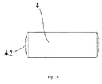
Fig. 16 is the schematically structural diagram ofEmbodiment 2 of the pin of the invention. - 1 shell; 1.1 hole I ; 1.2 plane A; 1.3 welding spot; 1.4 seam; 1.5 locking block I; 1.6 bayonet; 1.7 locking block II; 2 holder; 2.1 hole II; 2.2 baseplate I ; 2.3 baseplate II ; 2.4 groove; 2.5 boss; 2.6 rib; 3 roller; 4 pin; 4.1 plane B; 4.2 curved surface; 5 driving cam; 6 tappet.
- The present invention is further illustrated by embodiments and drawings hereinafter:
- The embodiment is: as shown in
Figs. 1 to 3 , a high-pressure oil pump roller tappet, which is used for an automobile fuel injection system, is mounted between a drivingcam 5 and atappet 6. The roller tappet includes ashell 1, aholder 2, aroller 3, and apin 4. Theshell 1 whose main structure is a cylindrical housing is made by bending a steel plate in a surrounding way. Planes A 1.2 that are in parallel and symmetrical with each other are arranged on both sides of a seam 1.4 on lateral sides of the shell. Holes I 1.1 are arranged at symmetrical positions on the two planes A 1.2. Theholder 2 is of a U-shaped. Holes II 2.1 are arranged at symmetrical positions on vertical plates. Theroller 3 is located in the middle of thepin 4. Two ends of thepin 4 pass through the holes I 1.1 and the holes II 2.1 respectively. - The steel plates on both ends of the seam 1.4 are pre-stamped to form inward recesses, and welding spots 1.3 are provided therein. A locking block is arranged on the seam 1.4 between the welding spots 1.3 or on the
shell 1 opposing the seam 1.4. The locking block is a sector cylinder made by stamping, which protrudes from the shell. The length of the locking block can be adjusted between the two welding spots to fit sizes of different oil pump cylinders. - In the embodiment of the invention, the
shell 1, theholder 2, and thepin 4 have many different variations. - Among them, variations of the
shell 1 include: - Embodiment 1: As shown in
Fig. 4 , all of the lateral planes of theshell 1 on which the planes A 1.2 located are of the planar structure. The locking block is a short locking block I 1.5. - Embodiment 2: As shown in
Fig. 5 , the lower portion of the lateral plane of theshell 1 on which the plane A 1.2 is located is a cylindrical structure. The locking block is the short locking block I 1.5 - Embodiment 3: As shown in
Fig. 6 , the lower portion of the lateral plane of theshell 1 on which the plane A 1.2 is located is of the cylindrical structure. The plane A 1.2 is stamped inwardly, and thereby a bayonet 1.6 is formed between the plane A 1.2 and the lower portion of the cylindrical structure. The vertical plates of theholder 2 can pass through the bayonet 1.6. The locking block is the short locking block I 1.5 Embodiment 4: As shown inFig. 7 , the lateral planes on theshell 1 on which the planes A 1.2 are located are all of the planar structure. The difference with respect toEmbodiment 1 is that the locking block is a longlocking block II 1. 7. - Obviously, the structure of the locking block II 1.7 in
Embodiment 4 of the shell 1.7 can also be applied toEmbodiment 2 andEmbodiment 3 - Moreover, in
Embodiment 1 andEmbodiment 4 of theshell 1, the weight can be reduced by punching holes in the plane A 1.2. - Among them, variations of the
holder 2 include: - Embodiment 1: As shown in
Fig. 8 , the baseplate of theholder 2 is the baseplate I 2.2 which has a projecting curved structure. - Embodiment 2: As shown in
Fig. 9 , the baseplate of theholder 2 is the baseplate II 2.3 which has a planar structure. - Embodiment 3: As shown in
Figs. 10 andFig. 11 , the baseplate of theholder 2 is the baseplate I 2.2 which has a projecting curved structure. A groove 2.4 is arranged on the underside of the baseplate I 2.2. A boss 2.5 is formed on the upper side of the baseplate I 2.2 accordingly. - Embodiment 4: As shown in
Figs. 12 andFig. 13 , the baseplate of theholder 2 is the baseplate II 2.3 which has a planar structure. A groove 2.4 is arranged on the underside of the baseplate II 2.3. A boss 2.5 is formed on the upper side of the baseplate II 2.3 accordingly. - Embodiment 5: As shown in
Fig. 14 , the baseplate of theholder 2 is the baseplate II 2.3 which has a planar structure. The difference with respect toEmbodiment 2 lies in that a plurality of the ribs 2.6 are arranged on bending parts between the vertical plates and the baseplate of theholder 2. - Obviously, the structure of the rib 2.6 in
Embodiment 5 of theholder 2 can also be applied toEmbodiment 1,Embodiment 3, andEmbodiment 4. - Among them, variations of the
pin 4 include: - Embodiment 1: As shown in
Fig. 15 , both ends of thepin 4 are of planes B 4.1. - Embodiment 2: As shown in
Fig. 16 , both ends of thepin 4 are of curved surfaces 4.2. The curvature of the curved surface 4.2 is the same as that of theshell 1. - Moreover, if necessary, when assembling, various embodiments of the
shell 1, theholder 2, and thepin 4 as described above can be combined freely. - The above is only the embodiments of the invention, but the structural features of the invention are not limited thereto. The invention can be used in similar production. Any changes or modifications made by a person with ordinary skill in this art that fall in the field of the invention, are within the patent scope of the invention.
Claims (10)
- A high-pressure oil pump roller tappet, used in an automobile fuel injection system, mounted between a driving cam (5) and a tappet (6), wherein: the roller tappet comprises a shell (1), a holder (2), a roller (3), and a pin (4); wherein the shell (1) whose main structure is a cylindrical housing is made by bending a steel plate in a surrounding way; wherein planes A (1.2) that are in parallel and symmetrical with each other are arranged on both sides of a seam (1.4) on lateral sides of the shell; wherein holes I (1.1) are arranged at symmetrical positions on the two planes A (1.2), wherein the holder (2) is of a U-shape, holes II (2.1) are arranged at symmetrical positions on vertical plates; wherein the roller (3) is located in the middle of the pin (4), and wherein two ends of the pin (4) passes through the holes I (1.1) and the holes II (2.1) respectively.
- The high-pressure oil pump roller tappet according to Claim 1, wherein steel plates on the both ends of the seam (1.4) are pre-stamped to form inward recesses, and welding spots (1.3) are provided therein.
- The high-pressure oil pump roller tappet according to Claim 2, wherein a locking block is arranged on the seam (1.4) between the welding spots (1.3) or on the shell 1 opposing the seam (1.4) ; wherein the locking block is a sector cylinder made by stamping, which protrudes from the shell; and wherein the locking block can be a short locking block I (1.5) or a long locking block II (1.7).
- The high-pressure oil pump roller tappet according to Claim 1, wherein all lateral planes of the shell (1) on which the planes A (1.2) located are of planar structure.
- The high-pressure oil pump roller tappet according to Claim 1, wherein a lower portion of a lateral plane on which the plane A (1.2) is located is of a cylindrical structure.
- The high-pressure oil pump roller tappet according to Claim 5, wherein the plane A (1.2) is stamped inwardly to form a bayonet (1.6) between the plane A (1.2) and a lower portion of the cylindrical structure; and wherein two vertical plates of the holder (2) can pass through the bayonet (1.6).
- The high-pressure oil pump roller tappet according to Claim 1, wherein the baseplate of the holder (2) can be a baseplate I (2.2) with a projecting curved surface structure or a baseplate II (2.3) with a planar structure.
- The high-pressure oil pump roller tappet according to Claim 7, wherein a groove (2.4) is arranged on the underside of the baseplate of the holder (2), and wherein a boss (2.5) is formed on the upper side of the baseplate of the holder accordingly.
- The high-pressure oil pump roller tappet according to Claim 1, wherein a plurality of ribs (2.6) are arranged on bending parts between vertical plates and baseplates of the holder (2).
- The high-pressure oil pump roller tappet according to Claim 1, wherein both ends of the pin (4) can be a plane B (4.1) or a curved surface (4.2), and wherein a curvature of the curved surface (4.2) is the same as that of the shell (1).
Applications Claiming Priority (2)
| Application Number | Priority Date | Filing Date | Title |
|---|---|---|---|
| CN201610351534.8A CN105863919B (en) | 2016-05-25 | 2016-05-25 | A kind of high-pressure oil pump roller tappet |
| CN201620486009.2U CN205618278U (en) | 2016-05-25 | 2016-05-25 | High -pressure oil pump roller tappet |
Publications (2)
| Publication Number | Publication Date |
|---|---|
| EP3249220A1 true EP3249220A1 (en) | 2017-11-29 |
| EP3249220B1 EP3249220B1 (en) | 2018-12-12 |
Family
ID=56737866
Family Applications (1)
| Application Number | Title | Priority Date | Filing Date |
|---|---|---|---|
| EP16176570.6A Not-in-force EP3249220B1 (en) | 2016-05-25 | 2016-06-28 | A high pressure oil pump roller tappet |
Country Status (3)
| Country | Link |
|---|---|
| US (1) | US9863382B2 (en) |
| EP (1) | EP3249220B1 (en) |
| JP (1) | JP2017210950A (en) |
Cited By (1)
| Publication number | Priority date | Publication date | Assignee | Title |
|---|---|---|---|---|
| WO2019237346A1 (en) * | 2018-06-15 | 2019-12-19 | 舍弗勒技术股份两合公司 | Fuel pump tappet |
Families Citing this family (5)
| Publication number | Priority date | Publication date | Assignee | Title |
|---|---|---|---|---|
| US10408093B2 (en) * | 2017-09-20 | 2019-09-10 | Hangzhou Xzb Tech Co., Ltd | Welded high-pressure fuel pump roller tappet |
| DE102019102289B3 (en) * | 2019-01-30 | 2020-03-05 | Schaeffler Technologies AG & Co. KG | Roller plunger for a fuel pump |
| JP2021032100A (en) * | 2019-08-21 | 2021-03-01 | 株式会社デンソー | Fuel injection pump |
| US11143059B2 (en) * | 2019-10-03 | 2021-10-12 | Koyo Bearings North America Llc | Tappet assembly with unground outer cup |
| US11149593B2 (en) * | 2019-10-03 | 2021-10-19 | Koyo Bearings North America Llc | Tappet assembly with formed anti-rotation alignment device |
Citations (4)
| Publication number | Priority date | Publication date | Assignee | Title |
|---|---|---|---|---|
| EP0770762A1 (en) * | 1995-10-27 | 1997-05-02 | EATON AUTOMOTIVE S.p.A. | Mechanical roller tappet |
| WO2002020953A1 (en) * | 2000-09-09 | 2002-03-14 | Mahle Ventiltrieb Gmbh | Roller tappet for an internal combustion engine |
| WO2013119214A1 (en) * | 2012-02-08 | 2013-08-15 | Koyo Bearings Usa Llc | Follower mechanism |
| CN104279014A (en) * | 2014-08-04 | 2015-01-14 | 武汉东方骏驰精密制造有限公司 | Novel anti-rotation rolling wheel ascending and descending tappet |
Family Cites Families (23)
| Publication number | Priority date | Publication date | Assignee | Title |
|---|---|---|---|---|
| GB1290691A (en) | 1969-01-23 | 1972-09-27 | ||
| US4549509A (en) | 1984-09-20 | 1985-10-29 | Burtchell Darrell A | Tappet |
| JPH0571441A (en) * | 1991-09-11 | 1993-03-23 | Nippondenso Co Ltd | Fuel injector |
| JPH05332222A (en) * | 1992-05-27 | 1993-12-14 | Nippondenso Co Ltd | Fuel injection pump |
| JP2592682Y2 (en) * | 1993-09-24 | 1999-03-24 | 日本精工株式会社 | Support mechanism for tilt steering device |
| DE19857376A1 (en) | 1998-12-12 | 2000-06-15 | Mahle Ventiltrieb Gmbh | Roller plunger |
| DE19958314A1 (en) | 1999-12-03 | 2001-06-07 | Mahle Ventiltrieb Gmbh | Roller plunger |
| DE102006045933A1 (en) * | 2006-09-28 | 2008-04-03 | Robert Bosch Gmbh | Plunger assembly for a high pressure pump and high pressure pump with at least one plunger assembly |
| JP5303468B2 (en) * | 2006-12-05 | 2013-10-02 | シャエフラー カーゲー | Mechanical tappets, especially for internal combustion engine fuel pumps |
| US7793583B2 (en) * | 2006-12-06 | 2010-09-14 | Schaeffler Kg | Mechanical tappet in particular for a fuel pump of an internal combustion engine |
| DE102007006320A1 (en) | 2007-02-08 | 2008-08-14 | Schaeffler Kg | Mechanical roller tappet for an internal combustion engine |
| JP4788705B2 (en) * | 2007-11-14 | 2011-10-05 | トヨタ自動車株式会社 | Lifter caulking structure |
| JP2009236041A (en) * | 2008-03-27 | 2009-10-15 | Toyota Motor Corp | Roller lifter structure of fuel pump |
| JP2010037997A (en) * | 2008-08-01 | 2010-02-18 | Denso Corp | Fuel supply pump |
| JP4930478B2 (en) * | 2008-09-04 | 2012-05-16 | トヨタ自動車株式会社 | Roller lifter, roller lifter manufacturing method, and liquid pump |
| JP3147175U (en) * | 2008-10-07 | 2008-12-18 | 孝和 宮▲崎▼ | Heavy equipment fall prevention device |
| DE102009013130A1 (en) * | 2009-03-13 | 2010-09-16 | Schaeffler Technologies Gmbh & Co. Kg | tappet |
| DE102009056306A1 (en) | 2009-11-30 | 2011-06-01 | Schaeffler Technologies Gmbh & Co. Kg | roller plunger |
| JP5496696B2 (en) | 2010-01-27 | 2014-05-21 | Ntn株式会社 | Tappet for pump |
| DE102012202566B4 (en) | 2012-02-20 | 2021-12-23 | Schaeffler Technologies AG & Co. KG | Roller plunger with finger-like stud holding means |
| EP2853738B1 (en) * | 2013-09-27 | 2016-04-27 | Aktiebolaget SKF | Mechanical system, injection pump and valve actuator comprising such a mechanical system and manufacturing method |
| DE102014206315A1 (en) | 2014-04-02 | 2015-10-08 | Schaeffler Technologies AG & Co. KG | Roller tappet for a reciprocating internal combustion engine |
| DE102014218961A1 (en) | 2014-09-22 | 2016-03-24 | Aktiebolaget Skf | Roller tappet and method of manufacturing a housing member of a roller tappet |
-
2016
- 2016-06-24 US US15/191,543 patent/US9863382B2/en not_active Expired - Fee Related
- 2016-06-27 JP JP2016126164A patent/JP2017210950A/en active Pending
- 2016-06-28 EP EP16176570.6A patent/EP3249220B1/en not_active Not-in-force
Patent Citations (4)
| Publication number | Priority date | Publication date | Assignee | Title |
|---|---|---|---|---|
| EP0770762A1 (en) * | 1995-10-27 | 1997-05-02 | EATON AUTOMOTIVE S.p.A. | Mechanical roller tappet |
| WO2002020953A1 (en) * | 2000-09-09 | 2002-03-14 | Mahle Ventiltrieb Gmbh | Roller tappet for an internal combustion engine |
| WO2013119214A1 (en) * | 2012-02-08 | 2013-08-15 | Koyo Bearings Usa Llc | Follower mechanism |
| CN104279014A (en) * | 2014-08-04 | 2015-01-14 | 武汉东方骏驰精密制造有限公司 | Novel anti-rotation rolling wheel ascending and descending tappet |
Cited By (3)
| Publication number | Priority date | Publication date | Assignee | Title |
|---|---|---|---|---|
| WO2019237346A1 (en) * | 2018-06-15 | 2019-12-19 | 舍弗勒技术股份两合公司 | Fuel pump tappet |
| CN111601964A (en) * | 2018-06-15 | 2020-08-28 | 舍弗勒技术股份两合公司 | Tappet for fuel pump |
| CN111601964B (en) * | 2018-06-15 | 2022-02-18 | 舍弗勒技术股份两合公司 | Tappet for fuel pump |
Also Published As
| Publication number | Publication date |
|---|---|
| US20170342951A1 (en) | 2017-11-30 |
| US9863382B2 (en) | 2018-01-09 |
| JP2017210950A (en) | 2017-11-30 |
| EP3249220B1 (en) | 2018-12-12 |
Similar Documents
| Publication | Publication Date | Title |
|---|---|---|
| US9863382B2 (en) | High pressure oil pump roller tappet | |
| US10464120B2 (en) | Method for producing forged crankshaft | |
| US10047640B2 (en) | Roller tappet and method for manufacturing a housing element of a roller tappet | |
| US10408093B2 (en) | Welded high-pressure fuel pump roller tappet | |
| CN105863919B (en) | A kind of high-pressure oil pump roller tappet | |
| EP3315763A1 (en) | High-pressure fuel pump actuator used in engine | |
| EP3278903B1 (en) | Method for producing forged crankshaft | |
| US20160153320A1 (en) | Valve-actuating lever for reciprocating-piston internal combustion engines | |
| US20200370447A1 (en) | Rocker arm for a valve train of an internal combustion engine, and method for the non-cutting production of an arm from steel sheet | |
| US6612276B2 (en) | Rocker arm for valve trains of internal combustion engines | |
| CN106471222A (en) | Roller tappet | |
| CN205618278U (en) | High -pressure oil pump roller tappet | |
| CN206092254U (en) | High -pressure oil pump roller tappet for engine | |
| JP5984775B2 (en) | Connecting rod and engine equipped with the same | |
| CN106438142B (en) | A kind of engine high-pressure oil pump roller tappet | |
| US6171077B1 (en) | Suspension spring support for hermetic compressors | |
| EP3443206B1 (en) | Tappet with sliding inner cup | |
| CN103492714B (en) | The spring base of push-rod assembly and high-pressure pump for high-pressure pump | |
| KR102294206B1 (en) | Follower mechanism with anti-rotation feature | |
| CN106574520B (en) | valve rocker | |
| JPH10205451A (en) | Reciprocating piston compressor | |
| CN207033714U (en) | A kind of high-pressure oil pump roller tappet for engine | |
| JP2005036710A (en) | Pump mounting structure | |
| KR20100027432A (en) | High-pressure fuel pump | |
| KR100220464B1 (en) | Connecting rod connection structure |
Legal Events
| Date | Code | Title | Description |
|---|---|---|---|
| PUAI | Public reference made under article 153(3) epc to a published international application that has entered the european phase |
Free format text: ORIGINAL CODE: 0009012 |
|
| STAA | Information on the status of an ep patent application or granted ep patent |
Free format text: STATUS: REQUEST FOR EXAMINATION WAS MADE |
|
| 17P | Request for examination filed |
Effective date: 20160713 |
|
| AK | Designated contracting states |
Kind code of ref document: A1 Designated state(s): AL AT BE BG CH CY CZ DE DK EE ES FI FR GB GR HR HU IE IS IT LI LT LU LV MC MK MT NL NO PL PT RO RS SE SI SK SM TR |
|
| AX | Request for extension of the european patent |
Extension state: BA ME |
|
| GRAP | Despatch of communication of intention to grant a patent |
Free format text: ORIGINAL CODE: EPIDOSNIGR1 |
|
| STAA | Information on the status of an ep patent application or granted ep patent |
Free format text: STATUS: GRANT OF PATENT IS INTENDED |
|
| INTG | Intention to grant announced |
Effective date: 20180912 |
|
| GRAS | Grant fee paid |
Free format text: ORIGINAL CODE: EPIDOSNIGR3 |
|
| GRAA | (expected) grant |
Free format text: ORIGINAL CODE: 0009210 |
|
| STAA | Information on the status of an ep patent application or granted ep patent |
Free format text: STATUS: THE PATENT HAS BEEN GRANTED |
|
| AK | Designated contracting states |
Kind code of ref document: B1 Designated state(s): AL AT BE BG CH CY CZ DE DK EE ES FI FR GB GR HR HU IE IS IT LI LT LU LV MC MK MT NL NO PL PT RO RS SE SI SK SM TR |
|
| REG | Reference to a national code |
Ref country code: GB Ref legal event code: FG4D |
|
| REG | Reference to a national code |
Ref country code: CH Ref legal event code: EP |
|
| REG | Reference to a national code |
Ref country code: AT Ref legal event code: REF Ref document number: 1076361 Country of ref document: AT Kind code of ref document: T Effective date: 20181215 |
|
| REG | Reference to a national code |
Ref country code: DE Ref legal event code: R096 Ref document number: 602016008011 Country of ref document: DE |
|
| REG | Reference to a national code |
Ref country code: IE Ref legal event code: FG4D |
|
| REG | Reference to a national code |
Ref country code: NL Ref legal event code: MP Effective date: 20181212 |
|
| REG | Reference to a national code |
Ref country code: LT Ref legal event code: MG4D |
|
| PG25 | Lapsed in a contracting state [announced via postgrant information from national office to epo] |
Ref country code: LV Free format text: LAPSE BECAUSE OF FAILURE TO SUBMIT A TRANSLATION OF THE DESCRIPTION OR TO PAY THE FEE WITHIN THE PRESCRIBED TIME-LIMIT Effective date: 20181212 Ref country code: FI Free format text: LAPSE BECAUSE OF FAILURE TO SUBMIT A TRANSLATION OF THE DESCRIPTION OR TO PAY THE FEE WITHIN THE PRESCRIBED TIME-LIMIT Effective date: 20181212 Ref country code: LT Free format text: LAPSE BECAUSE OF FAILURE TO SUBMIT A TRANSLATION OF THE DESCRIPTION OR TO PAY THE FEE WITHIN THE PRESCRIBED TIME-LIMIT Effective date: 20181212 Ref country code: NO Free format text: LAPSE BECAUSE OF FAILURE TO SUBMIT A TRANSLATION OF THE DESCRIPTION OR TO PAY THE FEE WITHIN THE PRESCRIBED TIME-LIMIT Effective date: 20190312 Ref country code: BG Free format text: LAPSE BECAUSE OF FAILURE TO SUBMIT A TRANSLATION OF THE DESCRIPTION OR TO PAY THE FEE WITHIN THE PRESCRIBED TIME-LIMIT Effective date: 20190312 Ref country code: HR Free format text: LAPSE BECAUSE OF FAILURE TO SUBMIT A TRANSLATION OF THE DESCRIPTION OR TO PAY THE FEE WITHIN THE PRESCRIBED TIME-LIMIT Effective date: 20181212 Ref country code: ES Free format text: LAPSE BECAUSE OF FAILURE TO SUBMIT A TRANSLATION OF THE DESCRIPTION OR TO PAY THE FEE WITHIN THE PRESCRIBED TIME-LIMIT Effective date: 20181212 |
|
| REG | Reference to a national code |
Ref country code: AT Ref legal event code: MK05 Ref document number: 1076361 Country of ref document: AT Kind code of ref document: T Effective date: 20181212 |
|
| PG25 | Lapsed in a contracting state [announced via postgrant information from national office to epo] |
Ref country code: GR Free format text: LAPSE BECAUSE OF FAILURE TO SUBMIT A TRANSLATION OF THE DESCRIPTION OR TO PAY THE FEE WITHIN THE PRESCRIBED TIME-LIMIT Effective date: 20190313 Ref country code: RS Free format text: LAPSE BECAUSE OF FAILURE TO SUBMIT A TRANSLATION OF THE DESCRIPTION OR TO PAY THE FEE WITHIN THE PRESCRIBED TIME-LIMIT Effective date: 20181212 Ref country code: SE Free format text: LAPSE BECAUSE OF FAILURE TO SUBMIT A TRANSLATION OF THE DESCRIPTION OR TO PAY THE FEE WITHIN THE PRESCRIBED TIME-LIMIT Effective date: 20181212 Ref country code: AL Free format text: LAPSE BECAUSE OF FAILURE TO SUBMIT A TRANSLATION OF THE DESCRIPTION OR TO PAY THE FEE WITHIN THE PRESCRIBED TIME-LIMIT Effective date: 20181212 |
|
| PG25 | Lapsed in a contracting state [announced via postgrant information from national office to epo] |
Ref country code: NL Free format text: LAPSE BECAUSE OF FAILURE TO SUBMIT A TRANSLATION OF THE DESCRIPTION OR TO PAY THE FEE WITHIN THE PRESCRIBED TIME-LIMIT Effective date: 20181212 |
|
| PG25 | Lapsed in a contracting state [announced via postgrant information from national office to epo] |
Ref country code: PT Free format text: LAPSE BECAUSE OF FAILURE TO SUBMIT A TRANSLATION OF THE DESCRIPTION OR TO PAY THE FEE WITHIN THE PRESCRIBED TIME-LIMIT Effective date: 20190412 Ref country code: CZ Free format text: LAPSE BECAUSE OF FAILURE TO SUBMIT A TRANSLATION OF THE DESCRIPTION OR TO PAY THE FEE WITHIN THE PRESCRIBED TIME-LIMIT Effective date: 20181212 Ref country code: PL Free format text: LAPSE BECAUSE OF FAILURE TO SUBMIT A TRANSLATION OF THE DESCRIPTION OR TO PAY THE FEE WITHIN THE PRESCRIBED TIME-LIMIT Effective date: 20181212 Ref country code: IT Free format text: LAPSE BECAUSE OF FAILURE TO SUBMIT A TRANSLATION OF THE DESCRIPTION OR TO PAY THE FEE WITHIN THE PRESCRIBED TIME-LIMIT Effective date: 20181212 |
|
| PG25 | Lapsed in a contracting state [announced via postgrant information from national office to epo] |
Ref country code: SM Free format text: LAPSE BECAUSE OF FAILURE TO SUBMIT A TRANSLATION OF THE DESCRIPTION OR TO PAY THE FEE WITHIN THE PRESCRIBED TIME-LIMIT Effective date: 20181212 Ref country code: EE Free format text: LAPSE BECAUSE OF FAILURE TO SUBMIT A TRANSLATION OF THE DESCRIPTION OR TO PAY THE FEE WITHIN THE PRESCRIBED TIME-LIMIT Effective date: 20181212 Ref country code: SK Free format text: LAPSE BECAUSE OF FAILURE TO SUBMIT A TRANSLATION OF THE DESCRIPTION OR TO PAY THE FEE WITHIN THE PRESCRIBED TIME-LIMIT Effective date: 20181212 Ref country code: RO Free format text: LAPSE BECAUSE OF FAILURE TO SUBMIT A TRANSLATION OF THE DESCRIPTION OR TO PAY THE FEE WITHIN THE PRESCRIBED TIME-LIMIT Effective date: 20181212 Ref country code: IS Free format text: LAPSE BECAUSE OF FAILURE TO SUBMIT A TRANSLATION OF THE DESCRIPTION OR TO PAY THE FEE WITHIN THE PRESCRIBED TIME-LIMIT Effective date: 20190412 |
|
| REG | Reference to a national code |
Ref country code: DE Ref legal event code: R097 Ref document number: 602016008011 Country of ref document: DE |
|
| PLBE | No opposition filed within time limit |
Free format text: ORIGINAL CODE: 0009261 |
|
| STAA | Information on the status of an ep patent application or granted ep patent |
Free format text: STATUS: NO OPPOSITION FILED WITHIN TIME LIMIT |
|
| PG25 | Lapsed in a contracting state [announced via postgrant information from national office to epo] |
Ref country code: SI Free format text: LAPSE BECAUSE OF FAILURE TO SUBMIT A TRANSLATION OF THE DESCRIPTION OR TO PAY THE FEE WITHIN THE PRESCRIBED TIME-LIMIT Effective date: 20181212 Ref country code: DK Free format text: LAPSE BECAUSE OF FAILURE TO SUBMIT A TRANSLATION OF THE DESCRIPTION OR TO PAY THE FEE WITHIN THE PRESCRIBED TIME-LIMIT Effective date: 20181212 Ref country code: AT Free format text: LAPSE BECAUSE OF FAILURE TO SUBMIT A TRANSLATION OF THE DESCRIPTION OR TO PAY THE FEE WITHIN THE PRESCRIBED TIME-LIMIT Effective date: 20181212 |
|
| 26N | No opposition filed |
Effective date: 20190913 |
|
| REG | Reference to a national code |
Ref country code: DE Ref legal event code: R119 Ref document number: 602016008011 Country of ref document: DE |
|
| PG25 | Lapsed in a contracting state [announced via postgrant information from national office to epo] |
Ref country code: MC Free format text: LAPSE BECAUSE OF FAILURE TO SUBMIT A TRANSLATION OF THE DESCRIPTION OR TO PAY THE FEE WITHIN THE PRESCRIBED TIME-LIMIT Effective date: 20181212 |
|
| REG | Reference to a national code |
Ref country code: CH Ref legal event code: PL |
|
| REG | Reference to a national code |
Ref country code: BE Ref legal event code: MM Effective date: 20190630 |
|
| PG25 | Lapsed in a contracting state [announced via postgrant information from national office to epo] |
Ref country code: TR Free format text: LAPSE BECAUSE OF FAILURE TO SUBMIT A TRANSLATION OF THE DESCRIPTION OR TO PAY THE FEE WITHIN THE PRESCRIBED TIME-LIMIT Effective date: 20181212 |
|
| PG25 | Lapsed in a contracting state [announced via postgrant information from national office to epo] |
Ref country code: DE Free format text: LAPSE BECAUSE OF NON-PAYMENT OF DUE FEES Effective date: 20200101 Ref country code: IE Free format text: LAPSE BECAUSE OF NON-PAYMENT OF DUE FEES Effective date: 20190628 |
|
| PG25 | Lapsed in a contracting state [announced via postgrant information from national office to epo] |
Ref country code: BE Free format text: LAPSE BECAUSE OF NON-PAYMENT OF DUE FEES Effective date: 20190630 Ref country code: CH Free format text: LAPSE BECAUSE OF NON-PAYMENT OF DUE FEES Effective date: 20190630 Ref country code: LU Free format text: LAPSE BECAUSE OF NON-PAYMENT OF DUE FEES Effective date: 20190628 Ref country code: LI Free format text: LAPSE BECAUSE OF NON-PAYMENT OF DUE FEES Effective date: 20190630 |
|
| PG25 | Lapsed in a contracting state [announced via postgrant information from national office to epo] |
Ref country code: FR Free format text: LAPSE BECAUSE OF NON-PAYMENT OF DUE FEES Effective date: 20190630 |
|
| GBPC | Gb: european patent ceased through non-payment of renewal fee |
Effective date: 20200628 |
|
| PG25 | Lapsed in a contracting state [announced via postgrant information from national office to epo] |
Ref country code: GB Free format text: LAPSE BECAUSE OF NON-PAYMENT OF DUE FEES Effective date: 20200628 |
|
| PG25 | Lapsed in a contracting state [announced via postgrant information from national office to epo] |
Ref country code: CY Free format text: LAPSE BECAUSE OF FAILURE TO SUBMIT A TRANSLATION OF THE DESCRIPTION OR TO PAY THE FEE WITHIN THE PRESCRIBED TIME-LIMIT Effective date: 20181212 |
|
| PG25 | Lapsed in a contracting state [announced via postgrant information from national office to epo] |
Ref country code: HU Free format text: LAPSE BECAUSE OF FAILURE TO SUBMIT A TRANSLATION OF THE DESCRIPTION OR TO PAY THE FEE WITHIN THE PRESCRIBED TIME-LIMIT; INVALID AB INITIO Effective date: 20160628 Ref country code: MT Free format text: LAPSE BECAUSE OF FAILURE TO SUBMIT A TRANSLATION OF THE DESCRIPTION OR TO PAY THE FEE WITHIN THE PRESCRIBED TIME-LIMIT Effective date: 20181212 |
|
| PG25 | Lapsed in a contracting state [announced via postgrant information from national office to epo] |
Ref country code: MK Free format text: LAPSE BECAUSE OF FAILURE TO SUBMIT A TRANSLATION OF THE DESCRIPTION OR TO PAY THE FEE WITHIN THE PRESCRIBED TIME-LIMIT Effective date: 20181212 |