EP3248852B1 - Verfahren zum betreiben einer verarbeitungseinrichtung für sensordaten eines in einem kraftfahrzeug angeordneten sensors und kraftfahrzeug - Google Patents
Verfahren zum betreiben einer verarbeitungseinrichtung für sensordaten eines in einem kraftfahrzeug angeordneten sensors und kraftfahrzeug Download PDFInfo
- Publication number
- EP3248852B1 EP3248852B1 EP17172191.3A EP17172191A EP3248852B1 EP 3248852 B1 EP3248852 B1 EP 3248852B1 EP 17172191 A EP17172191 A EP 17172191A EP 3248852 B1 EP3248852 B1 EP 3248852B1
- Authority
- EP
- European Patent Office
- Prior art keywords
- vehicle
- information
- movement
- sensor
- processing device
- Prior art date
- Legal status (The legal status is an assumption and is not a legal conclusion. Google has not performed a legal analysis and makes no representation as to the accuracy of the status listed.)
- Active
Links
Images


Classifications
-
- B—PERFORMING OPERATIONS; TRANSPORTING
- B60—VEHICLES IN GENERAL
- B60W—CONJOINT CONTROL OF VEHICLE SUB-UNITS OF DIFFERENT TYPE OR DIFFERENT FUNCTION; CONTROL SYSTEMS SPECIALLY ADAPTED FOR HYBRID VEHICLES; ROAD VEHICLE DRIVE CONTROL SYSTEMS FOR PURPOSES NOT RELATED TO THE CONTROL OF A PARTICULAR SUB-UNIT
- B60W40/00—Estimation or calculation of non-directly measurable driving parameters for road vehicle drive control systems not related to the control of a particular sub unit, e.g. by using mathematical models
- B60W40/02—Estimation or calculation of non-directly measurable driving parameters for road vehicle drive control systems not related to the control of a particular sub unit, e.g. by using mathematical models related to ambient conditions
- B60W40/04—Traffic conditions
-
- G—PHYSICS
- G01—MEASURING; TESTING
- G01S—RADIO DIRECTION-FINDING; RADIO NAVIGATION; DETERMINING DISTANCE OR VELOCITY BY USE OF RADIO WAVES; LOCATING OR PRESENCE-DETECTING BY USE OF THE REFLECTION OR RERADIATION OF RADIO WAVES; ANALOGOUS ARRANGEMENTS USING OTHER WAVES
- G01S13/00—Systems using the reflection or reradiation of radio waves, e.g. radar systems; Analogous systems using reflection or reradiation of waves whose nature or wavelength is irrelevant or unspecified
- G01S13/66—Radar-tracking systems; Analogous systems
- G01S13/72—Radar-tracking systems; Analogous systems for two-dimensional tracking, e.g. combination of angle and range tracking, track-while-scan radar
- G01S13/723—Radar-tracking systems; Analogous systems for two-dimensional tracking, e.g. combination of angle and range tracking, track-while-scan radar by using numerical data
-
- G—PHYSICS
- G01—MEASURING; TESTING
- G01S—RADIO DIRECTION-FINDING; RADIO NAVIGATION; DETERMINING DISTANCE OR VELOCITY BY USE OF RADIO WAVES; LOCATING OR PRESENCE-DETECTING BY USE OF THE REFLECTION OR RERADIATION OF RADIO WAVES; ANALOGOUS ARRANGEMENTS USING OTHER WAVES
- G01S13/00—Systems using the reflection or reradiation of radio waves, e.g. radar systems; Analogous systems using reflection or reradiation of waves whose nature or wavelength is irrelevant or unspecified
- G01S13/88—Radar or analogous systems specially adapted for specific applications
- G01S13/93—Radar or analogous systems specially adapted for specific applications for anti-collision purposes
- G01S13/931—Radar or analogous systems specially adapted for specific applications for anti-collision purposes of land vehicles
-
- G—PHYSICS
- G01—MEASURING; TESTING
- G01S—RADIO DIRECTION-FINDING; RADIO NAVIGATION; DETERMINING DISTANCE OR VELOCITY BY USE OF RADIO WAVES; LOCATING OR PRESENCE-DETECTING BY USE OF THE REFLECTION OR RERADIATION OF RADIO WAVES; ANALOGOUS ARRANGEMENTS USING OTHER WAVES
- G01S17/00—Systems using the reflection or reradiation of electromagnetic waves other than radio waves, e.g. lidar systems
- G01S17/02—Systems using the reflection of electromagnetic waves other than radio waves
- G01S17/06—Systems determining position data of a target
- G01S17/42—Simultaneous measurement of distance and other co-ordinates
-
- G—PHYSICS
- G01—MEASURING; TESTING
- G01S—RADIO DIRECTION-FINDING; RADIO NAVIGATION; DETERMINING DISTANCE OR VELOCITY BY USE OF RADIO WAVES; LOCATING OR PRESENCE-DETECTING BY USE OF THE REFLECTION OR RERADIATION OF RADIO WAVES; ANALOGOUS ARRANGEMENTS USING OTHER WAVES
- G01S17/00—Systems using the reflection or reradiation of electromagnetic waves other than radio waves, e.g. lidar systems
- G01S17/02—Systems using the reflection of electromagnetic waves other than radio waves
- G01S17/50—Systems of measurement based on relative movement of target
- G01S17/58—Velocity or trajectory determination systems; Sense-of-movement determination systems
-
- G—PHYSICS
- G01—MEASURING; TESTING
- G01S—RADIO DIRECTION-FINDING; RADIO NAVIGATION; DETERMINING DISTANCE OR VELOCITY BY USE OF RADIO WAVES; LOCATING OR PRESENCE-DETECTING BY USE OF THE REFLECTION OR RERADIATION OF RADIO WAVES; ANALOGOUS ARRANGEMENTS USING OTHER WAVES
- G01S17/00—Systems using the reflection or reradiation of electromagnetic waves other than radio waves, e.g. lidar systems
- G01S17/88—Lidar systems specially adapted for specific applications
- G01S17/93—Lidar systems specially adapted for specific applications for anti-collision purposes
- G01S17/931—Lidar systems specially adapted for specific applications for anti-collision purposes of land vehicles
-
- G—PHYSICS
- G01—MEASURING; TESTING
- G01S—RADIO DIRECTION-FINDING; RADIO NAVIGATION; DETERMINING DISTANCE OR VELOCITY BY USE OF RADIO WAVES; LOCATING OR PRESENCE-DETECTING BY USE OF THE REFLECTION OR RERADIATION OF RADIO WAVES; ANALOGOUS ARRANGEMENTS USING OTHER WAVES
- G01S7/00—Details of systems according to groups G01S13/00, G01S15/00, G01S17/00
- G01S7/48—Details of systems according to groups G01S13/00, G01S15/00, G01S17/00 of systems according to group G01S17/00
- G01S7/4802—Details of systems according to groups G01S13/00, G01S15/00, G01S17/00 of systems according to group G01S17/00 using analysis of echo signal for target characterisation; Target signature; Target cross-section
-
- G—PHYSICS
- G01—MEASURING; TESTING
- G01S—RADIO DIRECTION-FINDING; RADIO NAVIGATION; DETERMINING DISTANCE OR VELOCITY BY USE OF RADIO WAVES; LOCATING OR PRESENCE-DETECTING BY USE OF THE REFLECTION OR RERADIATION OF RADIO WAVES; ANALOGOUS ARRANGEMENTS USING OTHER WAVES
- G01S7/00—Details of systems according to groups G01S13/00, G01S15/00, G01S17/00
- G01S7/48—Details of systems according to groups G01S13/00, G01S15/00, G01S17/00 of systems according to group G01S17/00
- G01S7/4808—Evaluating distance, position or velocity data
-
- G—PHYSICS
- G06—COMPUTING; CALCULATING OR COUNTING
- G06F—ELECTRIC DIGITAL DATA PROCESSING
- G06F16/00—Information retrieval; Database structures therefor; File system structures therefor
- G06F16/70—Information retrieval; Database structures therefor; File system structures therefor of video data
- G06F16/78—Retrieval characterised by using metadata, e.g. metadata not derived from the content or metadata generated manually
- G06F16/783—Retrieval characterised by using metadata, e.g. metadata not derived from the content or metadata generated manually using metadata automatically derived from the content
- G06F16/7847—Retrieval characterised by using metadata, e.g. metadata not derived from the content or metadata generated manually using metadata automatically derived from the content using low-level visual features of the video content
- G06F16/7854—Retrieval characterised by using metadata, e.g. metadata not derived from the content or metadata generated manually using metadata automatically derived from the content using low-level visual features of the video content using shape
-
- G—PHYSICS
- G06—COMPUTING; CALCULATING OR COUNTING
- G06V—IMAGE OR VIDEO RECOGNITION OR UNDERSTANDING
- G06V10/00—Arrangements for image or video recognition or understanding
- G06V10/20—Image preprocessing
- G06V10/24—Aligning, centring, orientation detection or correction of the image
- G06V10/242—Aligning, centring, orientation detection or correction of the image by image rotation, e.g. by 90 degrees
-
- G—PHYSICS
- G06—COMPUTING; CALCULATING OR COUNTING
- G06V—IMAGE OR VIDEO RECOGNITION OR UNDERSTANDING
- G06V20/00—Scenes; Scene-specific elements
- G06V20/50—Context or environment of the image
- G06V20/56—Context or environment of the image exterior to a vehicle by using sensors mounted on the vehicle
-
- G—PHYSICS
- G01—MEASURING; TESTING
- G01S—RADIO DIRECTION-FINDING; RADIO NAVIGATION; DETERMINING DISTANCE OR VELOCITY BY USE OF RADIO WAVES; LOCATING OR PRESENCE-DETECTING BY USE OF THE REFLECTION OR RERADIATION OF RADIO WAVES; ANALOGOUS ARRANGEMENTS USING OTHER WAVES
- G01S13/00—Systems using the reflection or reradiation of radio waves, e.g. radar systems; Analogous systems using reflection or reradiation of waves whose nature or wavelength is irrelevant or unspecified
- G01S13/02—Systems using reflection of radio waves, e.g. primary radar systems; Analogous systems
- G01S13/50—Systems of measurement based on relative movement of target
- G01S13/58—Velocity or trajectory determination systems; Sense-of-movement determination systems
- G01S13/589—Velocity or trajectory determination systems; Sense-of-movement determination systems measuring the velocity vector
-
- G—PHYSICS
- G01—MEASURING; TESTING
- G01S—RADIO DIRECTION-FINDING; RADIO NAVIGATION; DETERMINING DISTANCE OR VELOCITY BY USE OF RADIO WAVES; LOCATING OR PRESENCE-DETECTING BY USE OF THE REFLECTION OR RERADIATION OF RADIO WAVES; ANALOGOUS ARRANGEMENTS USING OTHER WAVES
- G01S13/00—Systems using the reflection or reradiation of radio waves, e.g. radar systems; Analogous systems using reflection or reradiation of waves whose nature or wavelength is irrelevant or unspecified
- G01S13/86—Combinations of radar systems with non-radar systems, e.g. sonar, direction finder
- G01S13/865—Combination of radar systems with lidar systems
-
- G—PHYSICS
- G01—MEASURING; TESTING
- G01S—RADIO DIRECTION-FINDING; RADIO NAVIGATION; DETERMINING DISTANCE OR VELOCITY BY USE OF RADIO WAVES; LOCATING OR PRESENCE-DETECTING BY USE OF THE REFLECTION OR RERADIATION OF RADIO WAVES; ANALOGOUS ARRANGEMENTS USING OTHER WAVES
- G01S13/00—Systems using the reflection or reradiation of radio waves, e.g. radar systems; Analogous systems using reflection or reradiation of waves whose nature or wavelength is irrelevant or unspecified
- G01S13/86—Combinations of radar systems with non-radar systems, e.g. sonar, direction finder
- G01S13/867—Combination of radar systems with cameras
-
- G—PHYSICS
- G01—MEASURING; TESTING
- G01S—RADIO DIRECTION-FINDING; RADIO NAVIGATION; DETERMINING DISTANCE OR VELOCITY BY USE OF RADIO WAVES; LOCATING OR PRESENCE-DETECTING BY USE OF THE REFLECTION OR RERADIATION OF RADIO WAVES; ANALOGOUS ARRANGEMENTS USING OTHER WAVES
- G01S17/00—Systems using the reflection or reradiation of electromagnetic waves other than radio waves, e.g. lidar systems
- G01S17/66—Tracking systems using electromagnetic waves other than radio waves
-
- G—PHYSICS
- G01—MEASURING; TESTING
- G01S—RADIO DIRECTION-FINDING; RADIO NAVIGATION; DETERMINING DISTANCE OR VELOCITY BY USE OF RADIO WAVES; LOCATING OR PRESENCE-DETECTING BY USE OF THE REFLECTION OR RERADIATION OF RADIO WAVES; ANALOGOUS ARRANGEMENTS USING OTHER WAVES
- G01S13/00—Systems using the reflection or reradiation of radio waves, e.g. radar systems; Analogous systems using reflection or reradiation of waves whose nature or wavelength is irrelevant or unspecified
- G01S13/88—Radar or analogous systems specially adapted for specific applications
- G01S13/93—Radar or analogous systems specially adapted for specific applications for anti-collision purposes
- G01S13/931—Radar or analogous systems specially adapted for specific applications for anti-collision purposes of land vehicles
- G01S2013/9323—Alternative operation using light waves
-
- G—PHYSICS
- G01—MEASURING; TESTING
- G01S—RADIO DIRECTION-FINDING; RADIO NAVIGATION; DETERMINING DISTANCE OR VELOCITY BY USE OF RADIO WAVES; LOCATING OR PRESENCE-DETECTING BY USE OF THE REFLECTION OR RERADIATION OF RADIO WAVES; ANALOGOUS ARRANGEMENTS USING OTHER WAVES
- G01S13/00—Systems using the reflection or reradiation of radio waves, e.g. radar systems; Analogous systems using reflection or reradiation of waves whose nature or wavelength is irrelevant or unspecified
- G01S13/88—Radar or analogous systems specially adapted for specific applications
- G01S13/93—Radar or analogous systems specially adapted for specific applications for anti-collision purposes
- G01S13/931—Radar or analogous systems specially adapted for specific applications for anti-collision purposes of land vehicles
- G01S2013/9327—Sensor installation details
- G01S2013/93271—Sensor installation details in the front of the vehicles
Definitions
- the invention relates to a method for operating a processing device for sensor data of at least one sensor installed in a motor vehicle which detects objects in the surroundings of the motor vehicle and whose sensor data describe object points with a distance information, wherein the processing device determines objects from the sensor data and the movement of a vehicle traced object, wherein the tracking of the object takes place by means of a dynamic model, which uses a movement information describing the movement of the object in two coordinate directions.
- sensors In the generation of environmental models of a motor vehicle, more and more sensors are used, which not only image objects in the surroundings of the motor vehicle two-dimensionally, such as cameras, but also associate detected object points with distance or depth information. It is known to further process sensor data provided by the sensor by a processing device, wherein (feature) objects are determined by feature extraction from the object points. For further use of this data, for example for driver assistance systems, it is also necessary that a tracking of the movement of these objects (so-called “tracking”) takes place over several measuring cycles of the sensor. For this purpose, it is known to use a dynamics model in which the movement of the object in two coordinate directions is described, for example by a state vector having an x-component and a y-component of the movement speed.
- the invention is therefore an object of the invention to provide a contrast more reliable method of the type mentioned above, which enables robust tracking of objects especially in traffic situations with longitudinal and transverse traffic.
- This object is achieved by a method of the aforementioned type in which, according to the invention, provision is made for the processing device additionally to use orientation information in the context of the dynamics model when fulfilling an assignment criterion applied to the movement information and / or to a geometry information describing the geometric extension of the object, which comprises a bounding box with an orientation describing the yaw angle of the vehicle.
- the invention is based on the consideration of the conventionally used dynamic model, which uses a movement information describing the movement of the object in two coordinate directions to supplement the orientation information as soon as the motion information and / or the geometry information provide a sufficiently accurate statement about the actual orientation of the object Object representing vehicle permits. Only then is the bounding box, ie a particular rectangular envelope, which delimits the entire object, determined and with the on provide the yaw angle of the vehicle related orientation. In other words, the orientation information allows a statement about which longitudinal or transverse side of the represented vehicle corresponds to which side of the bounding box.
- the method according to the invention realizes the advantage that orientation ambiguities, which typically comprise four conceivable orientations of the vehicle within the bounding box, can be resolved. For example, it is possible to counteract the problem that the sensor detects the front and the driver side in one measurement cycle and the front and the passenger side of the vehicle in a subsequent measurement cycle, from which an undesired apparent movement of the object during the tracking is derived. Consequently, the method according to the invention provides more reliable information about the movement of the object, which information can be used in particular for driver assistance systems in the form of so-called intersection assistants.
- the objects in the vicinity of the motor vehicle are first detected by the sensor, which determines the distance information, which is also to be recorded as depth information, in particular through the use of transit time methods.
- the processing device determines objects from the sensor data, classifies them as vehicles, for example by classification algorithms known from the prior art, and carries out the tracking or "tracking" of these objects.
- the dynamic model used for this purpose describes the movement of the vehicle until the allocation criterion is fulfilled only by the movement information, ie in two coordinate directions.
- a Euclidean coordinate system whose x-coordinate direction typically corresponds to the transverse axis of the motor vehicle and whose y-coordinate direction corresponds to the longitudinal axis of the motor vehicle is expediently used for this purpose.
- the tracking of the object thus takes place up to the fulfillment of the assignment criterion irrespective of the orientation of the object. In other words, the typically four possible orientations of the vehicle represented by the object are treated equally.
- the method according to the invention is characterized in that the processing device evaluates the assignment criterion, which is applied to the movement information according to a first alternative of the invention.
- the processing device evaluates the assignment criterion, which is applied to the movement information according to a first alternative of the invention.
- it is checked, preferably on the basis of sensor data of several measurement cycles of the sensor, whether a possible orientation of the vehicle, ie its yaw angle, can be associated with the determined direction of movement of the object.
- the motion information describes the speed of the object decomposed into two components, in particular in the x-direction and y-direction.
- the yaw angle of the vehicle is expediently defined as an angular offset of the vehicle longitudinal axis or the vehicle transverse axis to a coordinate direction.
- the bounding box for the object is generated and assigned an orientation corresponding to the orientation of the vehicle. It is virtually switched to an extended dynamic model, which in addition to the conventional motion information additionally uses the orientation information and therefore allows a clear resolution of orientation ambiguities during the pursuit.
- the bounding box of several possible orientations is assigned to those for which the deviation of its orientation angle from the direction of movement of the object is minimal.
- a plurality of orientation angles ⁇ of the bounding box can be considered, wherein the orientation angle is assigned which has the smallest deviation from the direction of movement determined from the movement information.
- the movement information includes the speed of the object in the x and y directions
- the orientation angle ⁇ is assigned for the
- v x and v y describe the velocities of the object in the y- and x-directions, respectively, and atan2 describes an arctangent operator having two arguments.
- the assignment criterion applied to the movement information describes reaching a threshold value by a measure of an angular uncertainty of the direction of movement of the object.
- the degree of angular uncertainty describes the accuracy of the estimation of the direction of movement of the object by the processing device.
- the threshold is expediently chosen so that a sufficient for the intended use of the method security of the direction of movement can be assumed. Because tracking algorithms used to track objects, such as B. Kalman filter anyway such a measure or at least parameters from which the measure can be easily derived calculate, a particularly simple evaluation of the assignment criterion can be done.
- the measure of the angular uncertainty is determined as a function of the variance of at least one velocity in a coordinate direction and / or the covariance of velocities in the coordinate directions.
- the variance and the covariance are parameters that can arise when using the tracking algorithm, since they are used for the statistical determination of the direction of movement of the tracked object.
- such a measure of the angular uncertainty can be represented as follows: var v x ⁇ v y 2 - 2 ⁇ covar v x . v y ⁇ v x ⁇ v y + var v y ⁇ v x 2 v x 2 + v y 2
- the processing device for determining the object combines a plurality of object points into a segment delimited by a route or a plurality of routes and determines a reference point.
- the segmentation methods used for this purpose are known per se from the prior art and determine the coherent segment from a set of object points. If the sensor only faces one side of the object, the sensor essentially detects object points lying on a line, which are combined to form the segment (I-shape) having a segment. On the other hand, if the sensor faces at least two sides of the object, a set of object points is detected that has a corner-like course. From this, the two-segment segment (L-shape) can then be formed.
- the limitation of a segment forms the basis for the definition of the (complete) bounding box, so that the segment can also be understood as a partial bounding box.
- the reference point forms the point of attachment for the determination of the position of the object, this being expediently determined as the end point of the segment or as the intersection of two segments of the segment.
- the tracking of the movement of the object can then advantageously take place on the basis of the reference point. It is also particularly useful if the reference point describes a corner position of the vehicle. This allows a particularly simple association of the object to be determined with the detected vehicle.
- the assignment criterion applied to the geometry information may describe achieving a threshold for a ratio of two link lengths.
- the distances bounded by the reference point are used for this purpose.
- the size of the bounding box is adapted as a function of the orientation information and a geometry hypothesis for the vehicle.
- a correction of the size of the bounding box can be carried out on the basis of the geometry hypothesis which, for example, states that the longitudinal side of a vehicle is larger than the lateral side by a predetermined factor.
- the geometry hypothesis which, for example, states that the longitudinal side of a vehicle is larger than the lateral side by a predetermined factor.
- the assignment criterion applied to the movement information is used, since an initially determined size of the bounding box can deviate from the actual size of the detected vehicle due to object points only detected in fragmentary manner.
- the length of the longitudinal side of the vehicle can be determined simply on the basis of a determined length of the transverse side and vice versa.
- the output data of the processing device can serve as input data for a driver assistance system. It is therefore preferred if the processing device provides object information obtained from the tracking for vehicle systems that are evaluating in a transversal and longitudinal direction.
- the vehicle system may be a driver assistance system that evaluates traffic situations at a road intersection (so-called intersection assistant).
- intersection assistant the object data can be supplied directly to the vehicle system or initially be fused with output data of other sensor device of the motor vehicle to an environment model and then provided to the vehicle system.
- Fig. 1 shows a schematic diagram of a motor vehicle 1 in an exemplary traffic situation. It is located at a road intersection 2, which is currently being passed by a crossing vehicle 3.
- the motor vehicle 1 has a sensor device 4 with a plurality of sensors, wherein, for reasons of clarity, only a sensor 5 arranged in the front region of the motor vehicle is shown.
- the sensor 5 is designed to detect objects in the vicinity of the motor vehicle, wherein the sensor data describe object points with a distance information.
- the sensor 5 can accordingly be designed, for example, as a laser scanner, time-of-flight camera or as a radar sensor.
- the further sensors of the sensor device 4 can be arranged at further installation positions of the motor vehicle 1 and / or realized by different of the aforementioned sensor types.
- the sensor data are provided to a processing device 6.
- This generates object information, which objects in the environment of the motor vehicle 1, for example the vehicle 3, represent descriptive objects.
- the object information is evaluated by a vehicle system 7 in the form of a movement of vehicles in the environment of the motor vehicle 1 evaluating driver assistance system, for example, a so-called. Crossing Assistant.
- the processing device 6 is operable in accordance with a method described in more detail below with reference to the traffic situation: How out Fig. 1 Obviously, the sensor 5 detects the vehicle 3 in the region of its tail and its passenger side, where object points 8 describing sensor data are generated.
- the processing device 6 which combines the object points 8 by means of a segmentation algorithm into a segment 11 (L-shape) delimited by two distances 9, 10, which can also be regarded as a partial bounding box.
- the processing device 6 determines the point of intersection of the sections 9, 10 as the reference point 12 for further tracking the movement of an object representing the vehicle 3.
- the processing device 6 also carries out a corresponding classification algorithm which classifies the vehicle 3, initially detected only as an object, as such.
- the processing device 6 tracks the object via further measuring cycles of the sensor 5 using a dynamic model which uses a movement information describing the movement of the object in two coordinate directions x, y.
- the tracking thus takes place independently of the actual orientation of the vehicle 3, ie its yaw angle related to one of the coordinate directions x, y.
- four possible, in Fig. 2 shown alignments 13a-13d of the vehicle 3 treated as equivalent. Over the entire duration of the movement of the motor vehicle 3, however, this would be disadvantageous, since a possible misdetection of another corner position of the vehicle 3 as a reference point 12 in a later measuring cycle would result in an apparent movement of the object or even lead to a demolition of the pursuit.
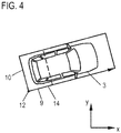
- an orientation information which comprises a (complete) bounding box 14 (cf. Fig. 4 ) with an orientation describing the yaw angle of the vehicle 3.
- the bounding box 14 is assigned, from a plurality of possible orientations corresponding to the orientations 13a to 13d, to those for which the deviation of its orientation angle ⁇ from the direction of movement of the object is minimal.
- the motion information describes the velocity of the object by velocity components in the x-direction and y-direction, so that the orientation angle ⁇ is assigned for the
- this assignment in other words a switching of the dynamics model, only takes place when an allocation criterion is met, ie as soon as the orientation can be determined with sufficient certainty.
- This is the assignment criterion is applied to the motion information and describes reaching a threshold by a measure of angular uncertainty of the direction of movement of the object.
- This measure determines the processing device 6 according to the following formula: var v x ⁇ v y 2 - 2 ⁇ covar v x . v y ⁇ v x ⁇ v y + var v y ⁇ v x 2 v x 2 + v y 2
- Var describe the variance and Covar the covariance.
- the corresponding values for the variances and covariance are calculated by using a Kalman filter as part of the object's tracking.
- FIG. 2 shows the determination of the actual orientation of the bounding box 14 again, by representing the offset of the segment 11 to a position 15 in a later measuring cycle of the sensor 5.
- the arrow 16 illustrates the direction of movement of the object in the form of a velocity vector, which is determined during the execution of the tracking algorithm using the Kalman filter. As can be seen, the arrow 16 does not point along the longitudinal axis of the vehicle 3. This offset makes it clear that the velocity vector can not be determined exactly by the tracking algorithm, but rather a certain angular uncertainty is given. Only if the measure is assessed to be small enough in the context of the assignment criterion does the additional use of the orientation information take place within the scope of the dynamics model.
- the side lengths of the bounding box 14 become a length adapted to the length of the route 10 and a multiple of the length of the route 10 described by the geometry hypothesis the route 9 determined.
- the above-described method can basically also be used if a segment 11 (I-shape) having only one segment is determined from the sensor data, that is, if the sensor 5 detects only object points 8 of a transverse or longitudinal side of the vehicle 3. Also in this case, a corresponding reference point 12 can be determined as the end point of the route, according to which a determination of a bounding box 14 with assignment of the orientation and an adaptation of the size of the bounding box 14 takes place as a function of the movement information.
- the assignment criterion is applied to a geometry information describing the geometric extension of the object. This is expedient in particular if, after one or more measuring cycles of the sensor 5, the side lengths of the vehicle 3 can be determined with sufficient accuracy, so that a statement about the orientation of the vehicle 3 is derived, again using a geometry hypothesis for the ratio of these side lengths leaves.
- the assignment of the orientation angle ⁇ then takes place analogously to the previously described embodiment, taking into account the movement information.
Description
- Die Erfindung betrifft ein Verfahren zum Betreiben einer Verarbeitungseinrichtung für Sensordaten wenigstens eines in einem Kraftfahrzeug verbauten Sensors, welcher Gegenstände in der Umgebung des Kraftfahrzeugs erfasst und dessen Sensordaten Gegenstandspunkte mit einer Abstandsinformation beschreiben, wobei die Verarbeitungseinrichtung aus den Sensordaten Objekte ermittelt und die Bewegung eines als Fahrzeug klassifizierten Objekts verfolgt, wobei die Verfolgung des Objekts mittels eines Dynamikmodells erfolgt, welches eine die Bewegung des Objekts in zwei Koordinatenrichtungen beschreibende Bewegungsinformation verwendet.
- Bei der Erzeugung von Umgebungsmodellen eines Kraftfahrzeugs kommen vermehrt Sensoren zum Einsatz, die Gegenstände in der Umgebung des Kraftfahrzeugs nicht lediglich zweidimensional abbilden, wie beispielsweise Kameras, sondern erfassten Gegenstandspunkten zusätzlich eine Abstands- bzw. Tiefeninformation zuordnen. Es ist bekannt, vom Sensor bereitgestellte Sensordaten durch eine Verarbeitungseinrichtung weiterzuverarbeiten, wobei durch Merkmalsextraktion aus den Gegenstandspunkten (logische) Objekte ermittelt werden. Zur weiteren Nutzung dieser Daten, beispielsweise für Fahrerassistenzsysteme, ist es zudem erforderlich, dass eine Verfolgung der Bewegung dieser Objekte (sog. "Tracking") über mehrere Messzyklen des Sensors erfolgt. Dazu ist es bekannt, ein Dynamikmodell einzusetzen, bei dem die Bewegung des Objekts in zwei Koordinatenrichtungen beschrieben wird, beispielsweise durch einen Zustandsvektor, der eine x-Komponente und eine y-Komponente der Bewegungsgeschwindigkeit aufweist.
- Nachteilig ist dabei jedoch, dass ein solches Dynamikmodell keine Informationen über die Ausrichtung, also den Gierwinkel, des durch das Objekt repräsentierten (realen) Fahrzeugs aufweist. Sofern die gewonnenen Informationen über das Objekt lediglich für Fahrerassistenzsysteme verwendet werden sollen, bei denen nur Verkehr in Längs- oder Querrichtung betrachtet wird, lässt sich unter der Zusatzannahme, dass der Verkehr nur in einer der vorgenannten Richtungen auftritt, die Ausrichtung eines Fahrzeugs bestimmen. Bei komplexeren Fahrerassistenzsystem, beispielsweise solchen, die den Fahrer an Straßenkreuzungen unterstützen sollen, lassen sich solche Zusatzannahmen jedoch nicht eindeutig treffen, so dass Scheinbewegungen des Objekts auftreten können oder die Verfolgung des Objekts gar abreißt. Der Artikel "Simultaneous Tracking and Shape Estimation with Laser Scanners" (erschienen in Intelligent Vehicles Symposium Proceedings 2014 IEEE, pp. 1205-1210, 2014) offenbart den Oberbegriff des Anspruchs 1. Der Erfindung liegt mithin die Aufgabe zugrunde, ein demgegenüber zuverlässigeres Verfahren der eingangs genannten Art anzugeben, welches insbesondere in Verkehrssituationen mit Längs- und Querverkehr eine robuste Verfolgung von Objekten ermöglicht.
Diese Aufgabe wird durch ein Verfahren der eingangs genannten Art gelöst, bei dem erfindungsgemäß vorgesehen ist, dass die Verarbeitungseinrichtung bei Erfüllung eines auf die Bewegungsinformation und/oder auf eine die geometrische Ausdehnung des Objekts beschreibende Geometrieinformation angewendeten Zuweisungskriteriums im Rahmen des Dynamikmodells zusätzlich eine Orientierungsinformation verwendet, welche eine Bounding Box mit einer den Gierwinkel des Fahrzeugs beschreibenden Orientierung umfasst.
Die Erfindung beruht auf der Überlegung, das herkömmlicherweise eingesetzte Dynamikmodell, welches eine die Bewegung des Objekts in zwei Koordinatenrichtungen beschreibenden Bewegungsinformation verwendet, um die Orientierungsinformation zu ergänzen, sobald die Bewegungsinformation und/oder die Geometrieinformation eine hinreichend genaue Aussage über die tatsächliche Ausrichtung des durch das Objekt repräsentierten Fahrzeugs zulässt. Erst dann wird die Bounding Box, also eine insbesondere rechteckige Einhüllende, die das gesamte Objekt begrenzt, ermittelt und mit der auf den Gierwinkel des Fahrzeugs bezogenen Orientierung versehen. Mit anderen Worten lässt die Orientierungsinformation eine Aussage darüber zu, welche Längs- bzw. Querseite des repräsentierten Fahrzeugs welcher Seite der Bounding Box entspricht. - Das erfindungsgemäße Verfahren realisiert den Vorteil, dass Orientierungsmehrdeutigkeiten, die typischerweise vier denkbare Ausrichtungen des Fahrzeugs innerhalb der Bounding Box umfassen, aufgelöst werden können. So kann beispielsweise dem Problem begegnet werden, dass der Sensor in einem Messzyklus die Front- und die Fahrerseite und in einem folgenden Messzyklus die Front- und die Beifahrerseite des Fahrzeugs erfasst, woraus eine unerwünschte Scheinbewegung des Objekts bei der Verfolgung abgeleitet wird. Durch das erfindungsgemäße Verfahren werden mithin zuverlässigere Informationen über die Bewegung des Objekts bereitgestellt, die insbesondere für Fahrerassistenzsysteme in Form von sog. Kreuzungsassistenten verwendet werden können.
- Dazu werden die Gegenstände in der Umgebung des Kraftfahrzeugs zunächst durch den Sensor, der insbesondere durch die Verwendung von Laufzeitverfahren die auch als Tiefeninformation aufzufassende Abstandsinformation ermittelt, erfasst. Die Verarbeitungseinrichtung ermittelt dann aus den Sensordaten Objekte, klassifiziert diese beispielsweise durch aus dem Stand der Technik bekannte Klassifikationsalgorithmen als Fahrzeuge und führt die Verfolgung bzw. das "Tracking" dieser Objekte durch. Das dazu eingesetzte Dynamikmodell beschreibt die Bewegung des Fahrzeugs dabei bis zur Erfüllung des Zuweisungskriteriums nur durch die Bewegungsinformation, also in zwei Koordinatenrichtungen. Zweckmäßigerweise wird dazu ein euklidisches Koordinatensystem verwendet, dessen x-Koordinatenrichtung typischerweise der Querachse des Kraftfahrzeugs und dessen y-Koordinatenrichtung der Längsachse des Kraftfahrzeugs entspricht. Die Verfolgung des Objekts erfolgt somit bis zur Erfüllung des Zuweisungskriteriums unabhängig von der Orientierung des Objekts. Mit anderen Worten werden die typischerweise vier möglichen Ausrichtungen des durch das Objekt repräsentierten Fahrzeugs gleichwertig behandelt.
- Das erfindungsgemäße Verfahren zeichnet sich nun dadurch aus, dass die Verarbeitungseinrichtung das Zuweisungskriterium auswertet, welches gemäß einer ersten Erfindungsalternative auf die Bewegungsinformation angewendet wird. In diesem Fall wird, bevorzugt auf Basis von Sensordaten mehrerer Messzyklen des Sensors, überprüft, ob sich eine mögliche Ausrichtung des Fahrzeugs, also dessen Gierwinkel, mit der ermittelten Bewegungsrichtung des Objekts assoziieren lässt. Bevorzugt beschreibt die Bewegungsinformation die in zwei Komponenten, insbesondere in x-Richtung und y-Richtung, zerlegte Geschwindigkeit des Objekts. Dementsprechend wird der Gierwinkel des Fahrzeugs zweckmäßigerweise als Winkelversatz der Fahrzeuglängsachse oder der Fahrzeugquerachse zu einer Koordinatenrichtung definiert. Gemäß einer zweiten Erfindungsalternative, die jedoch auch kombiniert mit der zuvor beschriebenen verwendet werden kann, wird im Rahmen des Zuweisungskriteriums überprüft, ob die geometrische Ausdehnung des Objekts, also insbesondere die geometrische Anordnung der Gegenstandspunkte, einen hinreichend genauen Rückschluss auf die Ausrichtung des Fahrzeugs zulässt.
- Bei beiden Erfindungsalternativen wird bei Erfüllung des Zuweisungskriteriums die Bounding Box für das Objekt erzeugt und dieser eine der Ausrichtung des Fahrzeugs entsprechende Orientierung zugewiesen. Es wird quasi auf ein erweitertes Dynamikmodell umgeschaltet, das neben der herkömmlichen Bewegungsinformation zusätzlich die Orientierungsinformation verwendet und daher eine eindeutige Auflösung von Orientierungsmehrdeutigkeiten während der Verfolgung ermöglicht.
- Es ist besonders vorteilhaft, wenn der Bounding Box von mehreren möglichen Orientierungen jene zugewiesen wird, für die die Abweichung ihres Orientierungswinkels von der Bewegungsrichtung des Objekts minimal ist. Es können mithin mehrere Orientierungswinkel ϕ der Bounding Box betrachtet werden, wobei jener Orientierungswinkel zugewiesen wird, der die geringste Abweichung zu der aus der Bewegungsinformation ermittelten Bewegungsrichtung aufweist. Umfasst die Bewegungsinformation dabei die Geschwindigkeit des Objekts in x- und y-Richtung, so wird jener Orientierungswinkel ϕ zugewiesen, für den

- Es wird zudem im Rahmen des erfindungsgemäßen Verfahrens bevorzugt, wenn das auf die Bewegungsinformation angewendete Zuweisungskriterium ein Erreichen eines Schwellwerts durch ein Maß einer Winkelunsicherheit der Bewegungsrichtung des Objekts beschreibt. Das Maß der Winkelunsicherheit beschreibt die Genauigkeit der Schätzung der Bewegungsrichtung des Objekts durch die Verarbeitungseinrichtung. Der Schwellwert wird dabei zweckmäßigerweise so gewählt, dass eine für die vorgesehene Verwendung des Verfahrens ausreichende Sicherheit der Bewegungsrichtung angenommen werden kann. Da für die Verfolgung von Objekten verwendete Tracking-Algorithmen wie z. B. Kalman-Filter ohnehin ein solches Maß oder zumindest Parameter, aus denen sich das Maß einfach ableiten lässt, berechnen, kann eine besonders einfache Auswertung des Zuweisungskriteriums erfolgen.
- Es ist von besonderem Vorteil, wenn das Maß für die Winkelunsicherheit in Abhängigkeit der Varianz wenigstens einer Geschwindigkeit in einer Koordinatenrichtung und/oder der Kovarianz von Geschwindigkeiten in den Koordinatenrichtungen ermittelt wird. Die Varianz und die Kovarianz sind dabei Parameter, die bei der Verwendung des Tracking-Algorithmus anfallen können, da sie der statistischen Ermittlung der Bewegungsrichtung des verfolgten Objekts dienen. Formelmäßig kann ein derart ermitteltes Maß für die Winkelunsicherheit wie folgt dargestellt werden:

- Dabei beschreiben die Operatoren Var die Varianz und Covar die Kovarianz.
- Bei dem erfindungsgemäßen Verfahren ist es besonders zweckmäßig, wenn die Verarbeitungseinrichtung zur Bestimmung des Objekts mehrere Gegenstandspunkte zu einem durch eine Strecke oder mehrere Strecken begrenzten Segment zusammenfasst und einen Referenzpunkt ermittelt. Die dazu werden verwendeten Segmentierungsverfahren sind an sich aus dem Stand der Technik bekannt und ermitteln aus einer Menge von Gegenstandspunkten das zusammenhängende Segment. Ist dem Sensor dabei lediglich eine Seite des Gegenstands zugewandt, erfasst der Sensor im Wesentlichen auf einer Linie liegende Gegenstandspunkte, die zu dem eine Strecke aufweisenden Segment (I-shape) zusammengefasst werden. Wenn dem Sensor dagegen wenigstens zwei Seiten des Gegenstands zugewandt sind, wird eine Menge von Gegenstandspunkten erfasst, die einen eckenartigen Verlauf aufweist. Daraus kann dann das zwei Strecken aufweisende Segment (L-shape) gebildet werden. Die Begrenzung eines Segments ist dabei Grundlage für die Definition der (vollständigen) Bounding Box, so dass das Segment auch als partielle Bounding Box aufgefasst werden kann.
- Der Referenzpunkt bildet dabei den Anknüpfungspunkt für die Bestimmung der Position des Objekts, wobei dieser zweckmäßigerweise als Endpunkt der Strecke oder als Schnittpunkt von zwei Strecken des Segments ermittelt wird. Die Verfolgung der Bewegung des Objekts kann dann vorteilhafterweise anhand des Referenzpunkts erfolgen. Es ist zudem besonders zweckmäßig, wenn der Referenzpunkt eine Eckposition des Fahrzeugs beschreibt. Dies ermöglicht eine besonders einfache Assoziierung des zu ermittelnden Objekts mit dem erfassten Fahrzeug.
- Das auf die Geometrieinformation angewendete Zuweisungskriterium kann das Erreichen eines Schwellwerts für ein Verhältnis von zwei Streckenlängen beschreiben. Bevorzugt werden dazu die durch den Referenzpunkt begrenzten Strecken verwendet. Auf Basis der Hypothese, dass die Front und das Heck eines Fahrzeugs wesentlich kürzer als dessen Längsseiten sind, kann so ein besonders einfacher Rückschluss auf die Ausrichtung des Fahrzeugs gezogen und die Orientierungsinformation auch in Abhängigkeit dieses Verhältnisses bestimmt werden.
- Bei dem erfindungsgemäßen Verfahren wird es darüber hinaus bevorzugt, wenn die Größe der Bounding Box in Abhängigkeit der Orientierungsinformation und einer Geometriehypothese für das Fahrzeug angepasst wird. Bei oder nach der Ermittlung der Bounding Box und der Feststellung der Orientierung des Fahrzeugs kann so anhand der Geometriehypothese, die beispielsweise besagt, dass die Längsseite eines Fahrzeugs um einen vorgegebenen Faktor größer als die Querseite ist, eine Korrektur der Größe der Bounding Box erfolgen. Dies ist besonders zweckmäßig, wenn das auf die Bewegungsinformation angewendete Zuweisungskriterium verwendet wird, da eine zunächst ermittelte Größe der Bounding Box aufgrund nur fragmentarisch erfasster Gegenstandspunkte von der tatsächlichen Größe des erfassten Fahrzeugs abweichen kann. Ist jedoch die Orientierung des Objekts bekannt, kann die Länge der Längsseite des Fahrzeugs einfach auf Basis einer ermittelten Länge der Querseite bestimmt werden und umgekehrt.
- Wie bereits angedeutet, können die Ausgangsdaten der Verarbeitungseinrichtung als Eingangsdaten für ein Fahrerassistenzsystem dienen. Es wird daher bevorzugt, wenn die Verarbeitungseinrichtung aus der Verfolgung gewonnene Objektinformationen für ein Bewegungen von Fahrzeugen in Quer- und Längsrichtung auswertendes Fahrzeugsystem bereitstellt. Das Fahrzeugsystem kann insbesondere ein Fahrerassistenzsystem sein, dass Verkehrssituationen an einer Straßenkreuzung (sog. Kreuzungsassistent) auswertet. Dabei können die Objektdaten dem Fahrzeugsystem unmittelbar zugeführt werden oder zunächst mit Ausgangsdaten anderer Sensoreinrichtung des Kraftfahrzeugs zu einem Umgebungsmodell fusioniert und dann dem Fahrzeugsystem bereitgestellt werden.
- Schließlich wird es bei dem erfindungsgemäßen Verfahren besonders bevorzugt, wenn als Sensor ein Laserscanner und/oder eine Time-of-Flight-Kamera und/oder ein Radarsensor verwendet wird. Diese Sensortypen basieren allesamt auf der Auswertung der Laufzeit von ausgesendeten elektromagnetischen Wellen und eignen sich daher hervorragend für die Erfassung der tiefenaufgelösten Gegenstandspunkte.
Daneben betrifft die Erfindung ein Kraftfahrzeug, umfassend einen in ihm verbauten Sensor zum Erfassen von Gegenständen in der Umgebung des Kraftfahrzeugs und zum Bereitstellen von Sensordaten, die eine Abstandsinformation aufweisende Gegenstandspunkte beschreiben, sowie eine Verarbeitungseinrichtung für die Sensordaten, welche gemäß dem erfindungsgemäßen Verfahren betrieben wird. Sämtliche Ausführungen zum erfindungsgemäßen Verfahren lassen sich analog auf das erfindungsgemäße Kraftfahrzeug übertragen, so dass auch mit diesem die zuvor genannten Vorteile erzielt werden können.
Weitere Vorteile und Einzelheiten der Erfindung ergeben sich aus den im Folgenden beschriebenen Ausführungsbeispielen sowie anhand der Zeichnungen. Diese sind schematische Darstellungen und zeigen: - Fig. 1
- eine Prinzipskizze eines erfindungsgemäßen Kraftfahrzeugs in einer exemplarischen Verkehrssituation;
- Fig. 2
- eine Darstellung mehrerer möglicher Orientierungen einer Bounding Box;
- Fig. 3
- eine Darstellung der Ermittlung der tatsächlichen Orientierung der Bounding Box; und
- Fig. 4
- eine Darstellung der Anpassung der Größe der Bounding Box.
-
Fig. 1 zeigt eine Prinzipskizze eines Kraftfahrzeugs 1 in einer exemplarischen Verkehrssituation. Es befindet sich an einer Straßenkreuzung 2, die gerade von einem querenden Fahrzeug 3 passiert wird. - Das Kraftfahrzeug 1 weist eine Sensoreinrichtung 4 mit mehreren Sensoren auf, wobei aus Gründen der Übersichtlichkeit lediglich ein im Frontbereich des Kraftfahrzeugs angeordneter Sensor 5 gezeigt ist. Der Sensor 5 ist dazu ausgebildet Gegenstände in der Umgebung des Kraftfahrzeugs zu erfassen, wobei dessen Sensordaten Gegenstandspunkte mit einer Abstandsinformation beschreiben. Der Sensor 5 kann dementsprechend beispielsweise als Laserscanner, Time-of-Flight-Kamera oder als Radarsensor ausgebildet sein. Die weiteren Sensoren der Sensoreinrichtung 4 können an weiteren Einbaupositionen des Kraftfahrzeugs 1 angeordnet und/oder durch unterschiedliche der vorgenannten Sensortypen realisiert sein.
- Die Sensordaten werden einer Verarbeitungseinrichtung 6 bereitgestellt. Diese erzeugt Objektinformationen, welche Gegenstände in der Umgebung des Kraftfahrzeugs 1, beispielsweise das Fahrzeug 3, beschreibende Objekte repräsentieren. Die Objektinformationen werden von einem Fahrzeugsystem 7 in Form eines Bewegungen von Fahrzeugen im Umfeld des Kraftfahrzeugs 1 auswertenden Fahrerassistenzsystems, beispielsweise eines sog. Kreuzungsassistenten, ausgewertet. Die Verarbeitungseinrichtung 6 ist gemäß eines im Folgenden anhand der Verkehrssituation näher beschriebenen Verfahrens betreibbar:
Wie ausFig. 1 ersichtlich erfasst der Sensor 5 das Fahrzeug 3 im Bereich dessen Hecks und dessen Beifahrerseite, wobei Gegenstandspunkte 8 beschreibende Sensordaten erzeugt werden. Diese werden der Verarbeitungseinrichtung 6 bereitgestellt, welche die Gegenstandspunkte 8 mittels eines Segmentierungsalgorithmus zu einem durch zwei Strecken 9, 10 begrenzten Segment 11 (L-Shape) zusammenfasst, welches auch als partielle Bounding Box aufgefasst werden kann. Zudem ermittelt die Verarbeitungseinrichtung 6 den Schnittpunkt der Strecken 9, 10 als Referenzpunkt 12 für die weitere Verfolgung der Bewegung eines das Fahrzeug 3 repräsentierenden Objekts. Dabei führt die Verarbeitungseinrichtung 6 auch einen entsprechenden Klassifikationsalgorithmus durch, der das zunächst nur als Gegenstand erfasste Fahrzeug 3 als solches klassifiziert. - Die Verarbeitungseinrichtung 6 verfolgt das Objekt über weitere Meßzyklen des Sensors 5 unter Einsatz eines Dynamikmodells, welches eine die Bewegung des Objekts in zwei Koordinatenrichtungen x, y beschreibende Bewegungsinformation verwendet. Die Verfolgung erfolgt mithin unabhängig von der tatsächlichen Ausrichtung des Fahrzeugs 3, also seines auf eine der Koordinatenrichtungen x, y bezogenen Gierwinkels. Mit anderen Worten werden vier mögliche, in
Fig. 2 gezeigte Ausrichtungen 13a-13d des Fahrzeugs 3 als gleichwertig behandelt. Über die gesamte Dauer der Bewegung des Kraftfahrzeugs 3 wäre dies jedoch nachteilhaft, da eine eventuelle Fehldetektion einer anderen Eckposition des Fahrzeugs 3 als Referenzpunkt 12 in einem späteren Meßzyklus eine Scheinbewegung des Objekts ergeben würde oder gar zu einem Abriss der Verfolgung führen könnte. - Um dieser Problematik zu begegnen, wird bei Erfüllung eines Zuweisungskriteriums im Rahmen des Dynamikmodells zusätzlich eine Orientierungsinformation verwendet, welche eine (vollständige) Bounding Box 14 (vgl.
Fig. 4 ) mit einer den Gierwinkel des Fahrzeugs 3 beschreibenden Orientierung umfasst. Dabei wird der Bounding Box 14 von mehreren möglichen - den Ausrichtungen 13a bis 13d entsprechenden - Orientierungen jene zugewiesen, für die die Abweichung ihres Orientierungswinkels ϕ von der Bewegungsrichtung des Objekts minimal ist. Dazu beschreibt die Bewegungsinformation die Geschwindigkeit des Objekts durch Geschwindigkeitskomponenten in x-Richtung und y-Richtung, so dass jener Orientierungswinkel ϕ zugewiesen wird, für den
- Diese Zuweisung, mit anderen Worten ein Umschalten des Dynamikmodells, erfolgt jedoch erst bei Erfüllung eines Zuweisungskriteriums, d.h. sobald die Orientierung mit hinreichender Sicherheit bestimmbar ist. Dazu wird das Zuweisungskriterium auf die Bewegungsinformation angewendet und beschreibt das Erreichen eines Schwellwerts durch ein Maß einer Winkelunsicherheit der Bewegungsrichtung des Objekts. Dieses Maß ermittelt die Verarbeitungseinrichtung 6 gemäß folgender Formel:

- Dabei beschreiben die Operatoren Var die Varianz und Covar die Kovarianz. Die entsprechenden Werte für die Varianzen und die Kovarianz werden durch die Verwendung eines Kalmann-Filters im Rahmen der Verfolgung des Objekts berechnet.
-
Fig. 3 zeigt die Ermittlung der tatsächlichen Orientierung der Bounding Box 14 nochmals, indem sie den Versatz des Segments 11 zu einer Position 15 bei einem späteren Meßzyklus des Sensors 5 darstellt. Der Pfeil 16 verdeutlicht dabei die Bewegungsrichtung des Objekts in Form eines Geschwindigkeitsvektors, der bei der Durchführung des das Kalman-Filter verwendenden Verfolgungsalgorithmus ermittelt wird. Ersichtlich weist der Pfeil 16 nicht entlang der Längsachse des Fahrzeugs 3. Dieser Versatz verdeutlicht, dass der Geschwindigkeitsvektor durch den Verfolgungsalgorithmus nicht exakt bestimmt werden kann, sondern eine gewisse Winkelunsicherheit gegeben ist. Erst wenn deren Maß im Rahmen des Zuweisungskriteriums als klein genug bewertet wird, erfolgt die zusätzliche Verwendung der Orientierungsinformation im Rahmen des Dynamikmodells. - Aus
Fig. 4 ist außerdem ersichtlich, dass die sich durch Ergänzung der Strecken 9, 10 des Segments 11 zu einem Rechteck theoretisch ergebende Größe der Bounding Box 14 keine korrekte Einhüllende des Fahrzeugs 3 darstellt. Es erfolgt dementsprechend zusätzlich eine Anpassung ihrer Größe, mit der die Bounding Box 14 dann weiter verwendet wird. Die Anpassung der Größe erfolgt in Abhängigkeit der Orientierungsinformation und einer Geometriehypothese für das Fahrzeug 3, welche ein anzunehmendes Verhältnis der Länge der Querseite eines Fahrzeugs zur Länge seiner Längsseite beschreibt. Nachdem aufgrund der Orientierungsinformation also bekannt ist, dass der Referenzpunkt 12 die beifahrerseitige Eckposition am Heck des Fahrzeugs 3 beschreibt, werden die Seitenlängen der Bounding Box 14 gemäß der Länge der Strecke 10 und einem durch die Geometriehypothese beschriebenen Vielfachen der Länge der Strecke 10 als angepasste Länge der Strecke 9 bestimmt. - Das zuvor beschriebene Verfahren ist grundsätzlich auch verwendbar, wenn aus den Sensordaten ein nur eine Strecke aufweisendes Segment 11 (I-Shape) ermittelt wird, also wenn der Sensor 5 lediglich Gegenstandspunkte 8 einer Quer- oder Längsseite des Fahrzeugs 3 erfasst. Auch in diesem Fall kann ein entsprechender Referenzpunkt 12 als Endpunkt der Strecke ermittelt werden, wonach in Abhängigkeit der Bewegungsinformation eine Ermittlung einer Bounding Box 14 mit Zuweisung der Orientierung und eine Anpassung der Größe der Bounding Box 14 erfolgen.
- Gemäß einem weiteren Ausführungsbeispiel des Verfahrens, das auch mit dem zuvor beschriebenen Ausgangsbeispiel kombiniert werden kann, wird das Zuweisungskriterium auf eine die geometrische Ausdehnung des Objekts beschreibende Geometrieinformation angewendet. Dies ist insbesondere dann zweckmäßig, wenn nach einem oder typischerweise mehreren Messzyklen des Sensors 5 die Seitenlängen des Fahrzeugs 3 hinreichend genau bestimmbar sind, so dass sich - abermals unter Anwendung einer Geometriehypothese für das Verhältnis dieser Seitenlängen - eine Aussage über die Ausrichtung des Fahrzeugs 3 ableiten lässt. Die Zuweisung des Orientierungswinkels ϕ erfolgt dann analog zu dem zuvor beschriebenen Ausführungsbeispiel unter Berücksichtigung der Bewegungsinformation.
Claims (12)
- Verfahren zum Betreiben einer Verarbeitungseinrichtung (6) für Sensordaten wenigstens eines in einem Kraftfahrzeug (1) verbauten Sensors (5), welcher Gegenstände in der Umgebung des Kraftfahrzeugs (1) erfasst und dessen Sensordaten Gegenstandspunkte (8) mit einer Abstandsinformation beschreiben, wobei die Verarbeitungseinrichtung (6) aus den Sensordaten Objekte ermittelt und die Bewegung eines als Fahrzeug (3) klassifizierten Objekts verfolgt, wobei die Verfolgung des Objekts mittels eines Dynamikmodells erfolgt, welches eine die Bewegung des Objekts in zwei Koordinatenrichtungen beschreibende Bewegungsinformation verwendet,
dadurch gekennzeichnet,
dass die Verarbeitungseinrichtung bei Erfüllung eines auf die Bewegungsinformation und/oder auf eine die geometrische Ausdehnung des Objekts beschreibende Geometrieinformation angewendeten Zuweisungskriteriums im Rahmen des Dynamikmodells zusätzlich eine Orientierungsinformation verwendet, welche eine Bounding Box (14) mit einer den Gierwinkel des Fahrzeugs (3) beschreibenden Orientierung umfasst. - Verfahren nach Anspruch 1,
dadurch gekennzeichnet,
dass der Bounding Box (14) von mehreren möglichen Orientierungen jene zugewiesen wird, für die die Abweichung ihres Orientierungswinkels (α) von der Bewegungsrichtung des Objekts minimal ist. - Verfahren nach Anspruch 1 oder 2,
dadurch gekennzeichnet,
dass das auf die Bewegungsinformation angewendete Zuweisungskriterium ein Erreichen eines Schwellwerts durch ein Maß einer Winkelunsicherheit der Bewegungsrichtung des Objekts beschreibt. - Verfahren nach Anspruch 3,
dadurch gekennzeichnet,
dass das Maß für die Winkelunsicherheit in Abhängigkeit der Varianz wenigstens einer Geschwindigkeit in einer Koordinatenrichtung und/oder der Kovarianz von Geschwindigkeiten in den Koordinatenrichtungen ermittelt wird. - Verfahren nach einem der vorhergehenden Ansprüche,
dadurch gekennzeichnet,
dass die Verarbeitungseinrichtung (6) zur Bestimmung des Objekts mehrere Gegenstandspunkte (8) zu einem durch eine Strecke oder mehrere Strecken (9, 10) begrenzten Segment (11) zusammenfasst und einen Referenzpunkt (12), insbesondere als Endpunkt der Strecke oder als Schnittpunkt von zwei Strecken (9, 10) des Segments (11), ermittelt. - Verfahren nach Anspruch 5,
dadurch gekennzeichnet,
dass das auf die Geometrieinformation angewendete Zuweisungskriterium das Erreichen eines Schwellwerts für ein Verhältnis von zwei Streckenlängen beschreibt. - Verfahren nach Anspruch 5 oder 6,
dadurch gekennzeichnet,
dass die Verfolgung der Bewegung des Objekts anhand des Referenzpunkts (12) erfolgt. - Verfahren nach einem der Ansprüche 5 bis 7,
dadurch gekennzeichnet,
dass der Referenzpunkt eine Eckposition des Fahrzeugs (3) beschreibt. - Verfahren nach einem der vorhergehenden Ansprüche,
dadurch gekennzeichnet,
dass die Größe der Bounding Box (14) in Abhängigkeit der Orientierungsinformation und einer Geometriehypothese für das Fahrzeug (3) angepasst wird. - Verfahren nach einem der vorhergehenden Ansprüche,
dadurch gekennzeichnet,
dass die Verarbeitungseinrichtung (6) aus der Verfolgung gewonnene Objektinformationen für ein Bewegungen von Fahrzeugen (3) in Quer- und Längsrichtung auswertendes Fahrzeugsystem (7) bereitstellt. - Verfahren nach einem der vorhergehenden Ansprüche,
dadurch gekennzeichnet,
dass als Sensor (5) ein Laserscanner und/oder eine Time-of-Flight-Kamera und/oder ein Radarsensor verwendet wird. - Kraftfahrzeug, umfassend einen in ihm verbauten Sensor (5) zum Erfassen von Gegenständen in der Umgebung des Kraftfahrzeugs (1) und zum Bereitstellen von Sensordaten, die eine Abstandsinformation aufweisende Gegenstandspunkte (8) beschreiben, sowie eine Verarbeitungseinrichtung (6) für die Sensordaten, welche zur Durchführung eines Verfahrens gemäß der Ansprüche 1 - 11 ausgebildet ist.
Applications Claiming Priority (1)
| Application Number | Priority Date | Filing Date | Title |
|---|---|---|---|
| DE102016006381.5A DE102016006381B3 (de) | 2016-05-24 | 2016-05-24 | Verfahren zum Betreiben einer Verarbeitungseinrichtung für Sensordaten eines in einem Kraftfahrzeug angeordneten Sensors und Kraftfahrzeug |
Publications (2)
| Publication Number | Publication Date |
|---|---|
| EP3248852A1 EP3248852A1 (de) | 2017-11-29 |
| EP3248852B1 true EP3248852B1 (de) | 2018-10-24 |
Family
ID=58765730
Family Applications (1)
| Application Number | Title | Priority Date | Filing Date |
|---|---|---|---|
| EP17172191.3A Active EP3248852B1 (de) | 2016-05-24 | 2017-05-22 | Verfahren zum betreiben einer verarbeitungseinrichtung für sensordaten eines in einem kraftfahrzeug angeordneten sensors und kraftfahrzeug |
Country Status (3)
| Country | Link |
|---|---|
| EP (1) | EP3248852B1 (de) |
| DE (1) | DE102016006381B3 (de) |
| ES (1) | ES2699501T3 (de) |
Families Citing this family (1)
| Publication number | Priority date | Publication date | Assignee | Title |
|---|---|---|---|---|
| DE102019102769A1 (de) * | 2019-02-05 | 2020-08-06 | Bayerische Motoren Werke Aktiengesellschaft | Verfahren und eine Vorrichtung zur Sensordatenfusion für ein Fahrzeug |
Family Cites Families (3)
| Publication number | Priority date | Publication date | Assignee | Title |
|---|---|---|---|---|
| JP2009042181A (ja) * | 2007-08-10 | 2009-02-26 | Denso Corp | 推定装置 |
| DE102008055932A1 (de) * | 2008-11-05 | 2010-05-06 | Iav Gmbh Ingenieurgesellschaft Auto Und Verkehr | Verfahren zur modellbasierten Simulation eines Verhaltens eines Sensors |
| DE102014210068A1 (de) * | 2014-05-27 | 2015-12-03 | Volkswagen Aktiengesellschaft | Verfahren zum Generieren eines Umfeldmodells eines Kraftfahrzeugs, Umfeldmodell und Fahrassistenzsystem |
-
2016
- 2016-05-24 DE DE102016006381.5A patent/DE102016006381B3/de not_active Expired - Fee Related
-
2017
- 2017-05-22 EP EP17172191.3A patent/EP3248852B1/de active Active
- 2017-05-22 ES ES17172191T patent/ES2699501T3/es active Active
Non-Patent Citations (1)
| Title |
|---|
| None * |
Also Published As
| Publication number | Publication date |
|---|---|
| ES2699501T3 (es) | 2019-02-11 |
| EP3248852A1 (de) | 2017-11-29 |
| DE102016006381B3 (de) | 2017-10-26 |
Similar Documents
| Publication | Publication Date | Title |
|---|---|---|
| EP2561419B1 (de) | Verfahren zur bestimmung des fahrbahnverlaufes für ein kraftfahrzeug | |
| DE102013113619B4 (de) | Probabilistische Zielauswahl und Gefahrbewertungsverfahren und Anwendung auf ein Kreuzungs-Kollisonswarnsystem | |
| EP1577682B1 (de) | Objektortungssystem für Kraftfahrzeuge zur Erkennung eines Spurwechsels | |
| EP1634243B1 (de) | Verfahren und vorrichtung zur objektortung für kraftfahrzeuge | |
| EP3332400B1 (de) | Verfahren und vorrichtung in einem kraftfahrzeug zur verbesserten datenfusionierung bei einer umfelderfassung | |
| DE102018218220A1 (de) | Steuergerät für ein Fahrzeug | |
| DE102005026386A1 (de) | Verfahren und Vorrichtung zum Bestimmen von Freiflächen in der Umgebung eines Fahrzeugs | |
| DE19629775A1 (de) | Verfahren und Vorrichtung zur Überwachung der Umgebung eines Fahrzeugs und zur Erfassung eines Ausfalls der Überwachungsvorrichtung | |
| DE102010006828A1 (de) | Verfahren zur automatischen Erstellung eines Modells der Umgebung eines Fahrzeugs sowie Fahrerassistenzsystem und Fahrzeug | |
| WO2003015053A1 (de) | Verfahren zur bestimmung einer modellfahrbahn | |
| EP1634241B1 (de) | Verfahren und vorrichtung zur objektbestimmung in fahrerassistenzsystemen für kraftfahrzeuge | |
| DE102007049706A1 (de) | Verfahren zur Schätzung der Relativbewegung von Video-Objekten und Fahrerassistenzsystem für Kraftfahrzeuge | |
| DE102014212866A1 (de) | Verfahren zum Ermitteln eines Parkplatzes aus einer Anzahl von Messpunkten | |
| DE102006039104A1 (de) | Verfahren zur Entfernungsmessung von Objekten auf von Bilddaten eines Monokamerasystems | |
| DE102010003375B4 (de) | Umfeldbewertungssystem in einem Fahrzeug mit Sensormitteln zur Erfassung von Objekten im Umfeld des Fahrzeuges | |
| DE102013202915A1 (de) | Verfahren und Vorrichtung zum Vermessen einer Parklücke für ein Einparkassistenzsystem eines Kraftfahrzeugs | |
| WO2015010902A1 (de) | Effizientes bereitstellen von belegungsinformationen für das umfeld eines fahrzeugs | |
| WO2015090691A1 (de) | Verfahren zum erzeugen eines umgebungsmodells eines kraftfahrzeugs, fahrerassistenzsystem und kraftfahrzeug | |
| EP3293971B1 (de) | Verfahren zur nachführung eines bildausschnitts | |
| EP3248852B1 (de) | Verfahren zum betreiben einer verarbeitungseinrichtung für sensordaten eines in einem kraftfahrzeug angeordneten sensors und kraftfahrzeug | |
| DE102019102923B4 (de) | Verfahren und eine Vorrichtung zur Sensordatenfusion für ein Fahrzeug | |
| DE102020105192A1 (de) | Verfahren zum Detektieren bewegter Objekte in einer Fahrzeugumgebung und Kraftfahrzeug | |
| DE102021207609A1 (de) | Verfahren zur Kennzeichnung eines Bewegungsweges | |
| EP2856205B1 (de) | Verfahren und vorrichtung zur objektdetektion | |
| DE102011056413A1 (de) | Freirauminformationen in einem Belegungsgitter als Grundlage für die Bestimmung eines Manöverraums für ein Fahrzeug |
Legal Events
| Date | Code | Title | Description |
|---|---|---|---|
| PUAI | Public reference made under article 153(3) epc to a published international application that has entered the european phase |
Free format text: ORIGINAL CODE: 0009012 |
|
| STAA | Information on the status of an ep patent application or granted ep patent |
Free format text: STATUS: THE APPLICATION HAS BEEN PUBLISHED |
|
| AK | Designated contracting states |
Kind code of ref document: A1 Designated state(s): AL AT BE BG CH CY CZ DE DK EE ES FI FR GB GR HR HU IE IS IT LI LT LU LV MC MK MT NL NO PL PT RO RS SE SI SK SM TR |
|
| AX | Request for extension of the european patent |
Extension state: BA ME |
|
| STAA | Information on the status of an ep patent application or granted ep patent |
Free format text: STATUS: REQUEST FOR EXAMINATION WAS MADE |
|
| 17P | Request for examination filed |
Effective date: 20180215 |
|
| RBV | Designated contracting states (corrected) |
Designated state(s): AL AT BE BG CH CY CZ DE DK EE ES FI FR GB GR HR HU IE IS IT LI LT LU LV MC MK MT NL NO PL PT RO RS SE SI SK SM TR |
|
| GRAP | Despatch of communication of intention to grant a patent |
Free format text: ORIGINAL CODE: EPIDOSNIGR1 |
|
| STAA | Information on the status of an ep patent application or granted ep patent |
Free format text: STATUS: GRANT OF PATENT IS INTENDED |
|
| RIC1 | Information provided on ipc code assigned before grant |
Ipc: G01S 17/66 20060101ALI20180508BHEP Ipc: G01S 5/02 20100101ALI20180508BHEP Ipc: B60W 40/103 20120101ALI20180508BHEP Ipc: B60W 40/109 20120101ALI20180508BHEP Ipc: B60W 40/114 20120101ALI20180508BHEP Ipc: B60W 50/00 20060101ALN20180508BHEP Ipc: B60W 40/04 20060101AFI20180508BHEP Ipc: G06F 17/30 20060101ALI20180508BHEP Ipc: G01S 17/93 20060101ALI20180508BHEP Ipc: G06K 9/32 20060101ALI20180508BHEP Ipc: B60W 40/105 20120101ALI20180508BHEP Ipc: G01S 17/58 20060101ALI20180508BHEP Ipc: B60W 40/107 20120101ALI20180508BHEP Ipc: G01S 17/06 20060101ALI20180508BHEP Ipc: G01S 7/48 20060101ALI20180508BHEP Ipc: G06K 9/00 20060101ALI20180508BHEP Ipc: G01S 17/42 20060101ALI20180508BHEP Ipc: G01S 17/87 20060101ALI20180508BHEP |
|
| RIC1 | Information provided on ipc code assigned before grant |
Ipc: G01S 17/42 20060101ALI20180516BHEP Ipc: G01S 7/48 20060101ALI20180516BHEP Ipc: B60W 40/114 20120101ALI20180516BHEP Ipc: B60W 50/00 20060101ALN20180516BHEP Ipc: G01S 17/93 20060101ALI20180516BHEP Ipc: B60W 40/109 20120101ALI20180516BHEP Ipc: B60W 40/105 20120101ALI20180516BHEP Ipc: G01S 17/06 20060101ALI20180516BHEP Ipc: B60W 40/103 20120101ALI20180516BHEP Ipc: G01S 17/58 20060101ALI20180516BHEP Ipc: G06K 9/32 20060101ALI20180516BHEP Ipc: B60W 40/04 20060101AFI20180516BHEP Ipc: G01S 17/87 20060101ALI20180516BHEP Ipc: G06F 17/30 20060101ALI20180516BHEP Ipc: G06K 9/00 20060101ALI20180516BHEP Ipc: G01S 17/66 20060101ALI20180516BHEP Ipc: B60W 40/107 20120101ALI20180516BHEP Ipc: G01S 5/02 20100101ALI20180516BHEP |
|
| INTG | Intention to grant announced |
Effective date: 20180608 |
|
| GRAS | Grant fee paid |
Free format text: ORIGINAL CODE: EPIDOSNIGR3 |
|
| GRAA | (expected) grant |
Free format text: ORIGINAL CODE: 0009210 |
|
| STAA | Information on the status of an ep patent application or granted ep patent |
Free format text: STATUS: THE PATENT HAS BEEN GRANTED |
|
| AK | Designated contracting states |
Kind code of ref document: B1 Designated state(s): AL AT BE BG CH CY CZ DE DK EE ES FI FR GB GR HR HU IE IS IT LI LT LU LV MC MK MT NL NO PL PT RO RS SE SI SK SM TR |
|
| REG | Reference to a national code |
Ref country code: CH Ref legal event code: EP |
|
| REG | Reference to a national code |
Ref country code: IE Ref legal event code: FG4D Free format text: LANGUAGE OF EP DOCUMENT: GERMAN |
|
| REG | Reference to a national code |
Ref country code: AT Ref legal event code: REF Ref document number: 1056319 Country of ref document: AT Kind code of ref document: T Effective date: 20181115 |
|
| REG | Reference to a national code |
Ref country code: DE Ref legal event code: R096 Ref document number: 502017000287 Country of ref document: DE |
|
| REG | Reference to a national code |
Ref country code: ES Ref legal event code: FG2A Ref document number: 2699501 Country of ref document: ES Kind code of ref document: T3 Effective date: 20190211 |
|
| REG | Reference to a national code |
Ref country code: NL Ref legal event code: MP Effective date: 20181024 |
|
| REG | Reference to a national code |
Ref country code: LT Ref legal event code: MG4D |
|
| PG25 | Lapsed in a contracting state [announced via postgrant information from national office to epo] |
Ref country code: NL Free format text: LAPSE BECAUSE OF FAILURE TO SUBMIT A TRANSLATION OF THE DESCRIPTION OR TO PAY THE FEE WITHIN THE PRESCRIBED TIME-LIMIT Effective date: 20181024 |
|
| PG25 | Lapsed in a contracting state [announced via postgrant information from national office to epo] |
Ref country code: LV Free format text: LAPSE BECAUSE OF FAILURE TO SUBMIT A TRANSLATION OF THE DESCRIPTION OR TO PAY THE FEE WITHIN THE PRESCRIBED TIME-LIMIT Effective date: 20181024 Ref country code: FI Free format text: LAPSE BECAUSE OF FAILURE TO SUBMIT A TRANSLATION OF THE DESCRIPTION OR TO PAY THE FEE WITHIN THE PRESCRIBED TIME-LIMIT Effective date: 20181024 Ref country code: IS Free format text: LAPSE BECAUSE OF FAILURE TO SUBMIT A TRANSLATION OF THE DESCRIPTION OR TO PAY THE FEE WITHIN THE PRESCRIBED TIME-LIMIT Effective date: 20190224 Ref country code: NO Free format text: LAPSE BECAUSE OF FAILURE TO SUBMIT A TRANSLATION OF THE DESCRIPTION OR TO PAY THE FEE WITHIN THE PRESCRIBED TIME-LIMIT Effective date: 20190124 Ref country code: PL Free format text: LAPSE BECAUSE OF FAILURE TO SUBMIT A TRANSLATION OF THE DESCRIPTION OR TO PAY THE FEE WITHIN THE PRESCRIBED TIME-LIMIT Effective date: 20181024 Ref country code: HR Free format text: LAPSE BECAUSE OF FAILURE TO SUBMIT A TRANSLATION OF THE DESCRIPTION OR TO PAY THE FEE WITHIN THE PRESCRIBED TIME-LIMIT Effective date: 20181024 Ref country code: BG Free format text: LAPSE BECAUSE OF FAILURE TO SUBMIT A TRANSLATION OF THE DESCRIPTION OR TO PAY THE FEE WITHIN THE PRESCRIBED TIME-LIMIT Effective date: 20190124 Ref country code: LT Free format text: LAPSE BECAUSE OF FAILURE TO SUBMIT A TRANSLATION OF THE DESCRIPTION OR TO PAY THE FEE WITHIN THE PRESCRIBED TIME-LIMIT Effective date: 20181024 |
|
| PG25 | Lapsed in a contracting state [announced via postgrant information from national office to epo] |
Ref country code: GR Free format text: LAPSE BECAUSE OF FAILURE TO SUBMIT A TRANSLATION OF THE DESCRIPTION OR TO PAY THE FEE WITHIN THE PRESCRIBED TIME-LIMIT Effective date: 20190125 Ref country code: SE Free format text: LAPSE BECAUSE OF FAILURE TO SUBMIT A TRANSLATION OF THE DESCRIPTION OR TO PAY THE FEE WITHIN THE PRESCRIBED TIME-LIMIT Effective date: 20181024 Ref country code: PT Free format text: LAPSE BECAUSE OF FAILURE TO SUBMIT A TRANSLATION OF THE DESCRIPTION OR TO PAY THE FEE WITHIN THE PRESCRIBED TIME-LIMIT Effective date: 20190224 Ref country code: AL Free format text: LAPSE BECAUSE OF FAILURE TO SUBMIT A TRANSLATION OF THE DESCRIPTION OR TO PAY THE FEE WITHIN THE PRESCRIBED TIME-LIMIT Effective date: 20181024 Ref country code: RS Free format text: LAPSE BECAUSE OF FAILURE TO SUBMIT A TRANSLATION OF THE DESCRIPTION OR TO PAY THE FEE WITHIN THE PRESCRIBED TIME-LIMIT Effective date: 20181024 |
|
| REG | Reference to a national code |
Ref country code: DE Ref legal event code: R097 Ref document number: 502017000287 Country of ref document: DE |
|
| PG25 | Lapsed in a contracting state [announced via postgrant information from national office to epo] |
Ref country code: CZ Free format text: LAPSE BECAUSE OF FAILURE TO SUBMIT A TRANSLATION OF THE DESCRIPTION OR TO PAY THE FEE WITHIN THE PRESCRIBED TIME-LIMIT Effective date: 20181024 Ref country code: DK Free format text: LAPSE BECAUSE OF FAILURE TO SUBMIT A TRANSLATION OF THE DESCRIPTION OR TO PAY THE FEE WITHIN THE PRESCRIBED TIME-LIMIT Effective date: 20181024 |
|
| PG25 | Lapsed in a contracting state [announced via postgrant information from national office to epo] |
Ref country code: RO Free format text: LAPSE BECAUSE OF FAILURE TO SUBMIT A TRANSLATION OF THE DESCRIPTION OR TO PAY THE FEE WITHIN THE PRESCRIBED TIME-LIMIT Effective date: 20181024 Ref country code: SK Free format text: LAPSE BECAUSE OF FAILURE TO SUBMIT A TRANSLATION OF THE DESCRIPTION OR TO PAY THE FEE WITHIN THE PRESCRIBED TIME-LIMIT Effective date: 20181024 Ref country code: EE Free format text: LAPSE BECAUSE OF FAILURE TO SUBMIT A TRANSLATION OF THE DESCRIPTION OR TO PAY THE FEE WITHIN THE PRESCRIBED TIME-LIMIT Effective date: 20181024 Ref country code: SM Free format text: LAPSE BECAUSE OF FAILURE TO SUBMIT A TRANSLATION OF THE DESCRIPTION OR TO PAY THE FEE WITHIN THE PRESCRIBED TIME-LIMIT Effective date: 20181024 |
|
| PLBE | No opposition filed within time limit |
Free format text: ORIGINAL CODE: 0009261 |
|
| STAA | Information on the status of an ep patent application or granted ep patent |
Free format text: STATUS: NO OPPOSITION FILED WITHIN TIME LIMIT |
|
| 26N | No opposition filed |
Effective date: 20190725 |
|
| PG25 | Lapsed in a contracting state [announced via postgrant information from national office to epo] |
Ref country code: SI Free format text: LAPSE BECAUSE OF FAILURE TO SUBMIT A TRANSLATION OF THE DESCRIPTION OR TO PAY THE FEE WITHIN THE PRESCRIBED TIME-LIMIT Effective date: 20181024 |
|
| PG25 | Lapsed in a contracting state [announced via postgrant information from national office to epo] |
Ref country code: MC Free format text: LAPSE BECAUSE OF FAILURE TO SUBMIT A TRANSLATION OF THE DESCRIPTION OR TO PAY THE FEE WITHIN THE PRESCRIBED TIME-LIMIT Effective date: 20181024 |
|
| REG | Reference to a national code |
Ref country code: BE Ref legal event code: MM Effective date: 20190531 |
|
| PG25 | Lapsed in a contracting state [announced via postgrant information from national office to epo] |
Ref country code: LU Free format text: LAPSE BECAUSE OF NON-PAYMENT OF DUE FEES Effective date: 20190522 |
|
| PG25 | Lapsed in a contracting state [announced via postgrant information from national office to epo] |
Ref country code: TR Free format text: LAPSE BECAUSE OF FAILURE TO SUBMIT A TRANSLATION OF THE DESCRIPTION OR TO PAY THE FEE WITHIN THE PRESCRIBED TIME-LIMIT Effective date: 20181024 |
|
| PG25 | Lapsed in a contracting state [announced via postgrant information from national office to epo] |
Ref country code: IE Free format text: LAPSE BECAUSE OF NON-PAYMENT OF DUE FEES Effective date: 20190522 |
|
| PG25 | Lapsed in a contracting state [announced via postgrant information from national office to epo] |
Ref country code: BE Free format text: LAPSE BECAUSE OF NON-PAYMENT OF DUE FEES Effective date: 20190531 |
|
| PG25 | Lapsed in a contracting state [announced via postgrant information from national office to epo] |
Ref country code: LI Free format text: LAPSE BECAUSE OF NON-PAYMENT OF DUE FEES Effective date: 20200531 Ref country code: CH Free format text: LAPSE BECAUSE OF NON-PAYMENT OF DUE FEES Effective date: 20200531 |
|
| PG25 | Lapsed in a contracting state [announced via postgrant information from national office to epo] |
Ref country code: CY Free format text: LAPSE BECAUSE OF FAILURE TO SUBMIT A TRANSLATION OF THE DESCRIPTION OR TO PAY THE FEE WITHIN THE PRESCRIBED TIME-LIMIT Effective date: 20181024 |
|
| PG25 | Lapsed in a contracting state [announced via postgrant information from national office to epo] |
Ref country code: MT Free format text: LAPSE BECAUSE OF FAILURE TO SUBMIT A TRANSLATION OF THE DESCRIPTION OR TO PAY THE FEE WITHIN THE PRESCRIBED TIME-LIMIT Effective date: 20181024 Ref country code: HU Free format text: LAPSE BECAUSE OF FAILURE TO SUBMIT A TRANSLATION OF THE DESCRIPTION OR TO PAY THE FEE WITHIN THE PRESCRIBED TIME-LIMIT; INVALID AB INITIO Effective date: 20170522 |
|
| PG25 | Lapsed in a contracting state [announced via postgrant information from national office to epo] |
Ref country code: MK Free format text: LAPSE BECAUSE OF FAILURE TO SUBMIT A TRANSLATION OF THE DESCRIPTION OR TO PAY THE FEE WITHIN THE PRESCRIBED TIME-LIMIT Effective date: 20181024 |
|
| P01 | Opt-out of the competence of the unified patent court (upc) registered |
Effective date: 20230530 |
|
| REG | Reference to a national code |
Ref country code: AT Ref legal event code: MM01 Ref document number: 1056319 Country of ref document: AT Kind code of ref document: T Effective date: 20220522 |
|
| PG25 | Lapsed in a contracting state [announced via postgrant information from national office to epo] |
Ref country code: AT Free format text: LAPSE BECAUSE OF NON-PAYMENT OF DUE FEES Effective date: 20220522 |
|
| PGFP | Annual fee paid to national office [announced via postgrant information from national office to epo] |
Ref country code: IT Payment date: 20230529 Year of fee payment: 7 Ref country code: FR Payment date: 20230523 Year of fee payment: 7 Ref country code: ES Payment date: 20230601 Year of fee payment: 7 Ref country code: DE Payment date: 20230531 Year of fee payment: 7 |
|
| PGFP | Annual fee paid to national office [announced via postgrant information from national office to epo] |
Ref country code: GB Payment date: 20230526 Year of fee payment: 7 |