EP3248803B1 - Printing apparatus with access portions for access to inside of housing - Google Patents
Printing apparatus with access portions for access to inside of housing Download PDFInfo
- Publication number
- EP3248803B1 EP3248803B1 EP17171261.5A EP17171261A EP3248803B1 EP 3248803 B1 EP3248803 B1 EP 3248803B1 EP 17171261 A EP17171261 A EP 17171261A EP 3248803 B1 EP3248803 B1 EP 3248803B1
- Authority
- EP
- European Patent Office
- Prior art keywords
- access
- printing apparatus
- housing
- face
- components
- Prior art date
- Legal status (The legal status is an assumption and is not a legal conclusion. Google has not performed a legal analysis and makes no representation as to the accuracy of the status listed.)
- Active
Links
Images


Classifications
-
- B—PERFORMING OPERATIONS; TRANSPORTING
- B41—PRINTING; LINING MACHINES; TYPEWRITERS; STAMPS
- B41J—TYPEWRITERS; SELECTIVE PRINTING MECHANISMS, i.e. MECHANISMS PRINTING OTHERWISE THAN FROM A FORME; CORRECTION OF TYPOGRAPHICAL ERRORS
- B41J29/00—Details of, or accessories for, typewriters or selective printing mechanisms not otherwise provided for
- B41J29/02—Framework
-
- B—PERFORMING OPERATIONS; TRANSPORTING
- B41—PRINTING; LINING MACHINES; TYPEWRITERS; STAMPS
- B41J—TYPEWRITERS; SELECTIVE PRINTING MECHANISMS, i.e. MECHANISMS PRINTING OTHERWISE THAN FROM A FORME; CORRECTION OF TYPOGRAPHICAL ERRORS
- B41J29/00—Details of, or accessories for, typewriters or selective printing mechanisms not otherwise provided for
- B41J29/12—Guards, shields or dust excluders
- B41J29/13—Cases or covers
Definitions
- the present invention relates to a printing apparatus including a housing.
- a housing of a printing apparatus is provided with a door and the like which a person such as a user uses to access components of the printing apparatus housed in the housing in various operations, maintenance, and the like.
- a housing is provided with an operation panel which functions as a door for accessing parts in a control area of an apparatus upper portion and with a front door for accessing parts in an ink area on a front side of an apparatus lower portion.
- this printing apparatus further includes a partition door which partitions a drive system area on a back side and the ink area on the front side in the apparatus lower portion, and from which parts in the drive system area can be accessed.
- US 9,302,516 B2 discloses a liquid jetting apparatus which includes a casing, a tank formed with a liquid storage chamber which stores liquid, an inlet which allows the liquid to be poured into the liquid storage chamber, and a liquid outflow channel which allows the liquid to flow out from the liquid storage chamber, a conveying mechanism which conveys a recording medium along a conveying path extending in a front-rear direction, a carriage which moves in a left-right direction, and a head mounted on the carriage and having a nozzle which jets the liquid onto the recording medium conveyed by the conveying mechanism.
- the tank, the conveying path, and the carriage are arranged inside the casing, the tank is arranged outside the conveying path in the left-right direction, and at least a part of the tank is arranged inside both ends of a movement area of the carriage in the left-right direction.
- US 6,280,018 B1 discloses a shuttle system transferring an ink-jet pen between a carriage and a shuttle access location on a printer front panel.
- a pen load button When a pen load button is pushed, the shuttle will move to an access position. In the access position, the shuttle will open a door and come beyond the front face of the printer. This allows the user to drop the pen(s) into place on the shuttle. Then when the button is pushed again, the pen shuttle will transfer the pens back into the printer, with the door closing, and automatically loads the pen(s) into the printer carriage without manual user intervention. The pen shuttle will then move to a rest position for normal printer operation. If the pen load button is pressed again, the pen shuttle moves back to the carriage and unloads the pen(s) automatically. The pen shuttle again opens the access door and presents the pens to the user.
- the shuttle has pen wipers and capping structures mounted for movement with the shuttle, allowing for pen service functions to be performed without the need for an additional service station.
- US 2008/0094987 A1 discloses a media storage which is adapted to store a plate-shaped medium.
- a media drive is operable to write data in the medium.
- a label printer is operable to print on the medium.
- a media conveyer is operable to convey the medium between the media storage, the media drive and the label printer.
- a casing defines an interior space of the media processor.
- a plateshaped frame divides the interior space into a first space located in a rear upper portion of the interior space, a second space located in a rear lower portion of the interior space and a front space located in a front portion of the interior space.
- the media drive is disposed in the first space.
- the label printer is disposed in the second space.
- the media storage and the media conveyer are disposed in the front space.
- JP 2004 130 578 A discloses an apparatus conformed to trends in the users' business world by giving antibacterial properties to a good-visibility, good-operability, low-cost and high-reliability apparatus enclosure part for an operation panel when the apparatus of good maintainability is to be provided even if an apparatus interior is divided by function, and an operation panel part to be a display and input part is constructed in a door structure to improve the maintainability.
- a partition plate for dividing the apparatus interior above and below, a door-shaped partition plate for further partitioning the lower space divided by the partition plate, and two upper and lower doors at the apparatus enclosure part.
- a mounting structure for these plates and doors is devised.
- a cooling fan for evenly and efficiently cooling the apparatus interior, an air inlet and an air outlet are arranged.
- a used material of an apparatus enclosure component is a special grade one proposable to customers.
- US 2009/0274342 A1 discloses a method for automated image quality based diagnosis of a document printing system.
- the method comprises receiving image data to be printed on a document; printing an image on the document based on the image data; scanning the printed image on the document with a sensor; analyzing the scanned printed image with an image quality analysis module to identify one or more defects in the printed image; automatically generating test pattern image data based on the one or more identified defects; and printing and analysing a test pattern image based on the test pattern image data.
- EP 2 487 041 A2 discloses an image forming apparatus which includes a main body, a cover member, and a support member.
- the cover member is at least partially flexible, has a bottom opening, and is dimensioned to entirely cover the apparatus except for a bottom face of the apparatus.
- the support member is pivotably supported on the main body, and has base end portions supported on the main body and a front end portion to support a portion of the cover member. With a pivotal movement of the support member, the cover member displaces and deforms and an end of the bottom opening of the cover member moves upward to expose a portion of the apparatus to be accessed by a user.
- US 2012/0293583 A1 discloses an image forming apparatus which includes a main body and a printing assembly.
- the printing assembly includes a carriage, an encoder scale, an encoder sensor, and a flexible cable.
- the carriage has a head mounting part and a board mounting part arranged along a direction perpendicular to the main scanning direction.
- the head mounting part mounts a recording head.
- the board mounting part mounts both the sensor and a carriage- side circuit board connected to the cable.
- a housing of the body has a first cover portion to cover an area opposing the head mounting part and a second cover portion to cover an area opposing the board mounting part.
- the first cover portion is openably disposed at the body to allow a user to open the first cover portion.
- the second cover portion is stationarily fixed at the body to prevent a user from opening the second cover portion.
- US 2015/0258800 A1 discloses a recording apparatus including a recording head that can eject an ink onto a sheet, a transport unit that transports the sheet to the recording head, a housing that contains the recording head and the transport unit, a case that is arranged on an outer surface of the housing so that the bottom portion thereof is positioned higher than a bottom surface of the housing, and that serves as a holder which holds an ink container containing an ink, and a supply unit that supplies the ink from the ink container to the recording head.
- the user has to open the front door and the partition door to access the parts in the drive system area. Accordingly, the parts in the drive system area are more troublesome for the user to access than the parts in the control area which can be accessed by just opening the operation panel and the parts in the ink area which can be accessed by just opening the front door.
- the components in the housing of the printing apparatus sometimes vary in accessibility depending on the positions thereof.
- the user and a service man who performs maintenance and the like of the printing apparatus are main persons who access the components in the housing of the printing apparatus. Meanwhile, in general, not all of the components are accessed evenly at the same frequency by either of the user and the service man.
- An object of the present invention is to provide a printing apparatus improved in convenience in cases where a user and a service man access components in a housing of the printing apparatus.
- a printing apparatus in accordance with the present invention is defined by claim 1.
- Dependent claims relate to preferred embodiments.
- the printing apparatus With the printing apparatus according to the present invention, it is possible to reduce occurrence of a situation where the components of the printing apparatus to be accessed by the user and the service man are arranged at positions with low accessibility. As a result, the convenience in cases where the user and the service man access the components in the housing of the printing apparatus can be improved.
- the housing includes two divided housings divided in a front-rear direction of the printing apparatus.
- the plurality of access portions may include a front face of the housing, a rear face of the housing, a side face of the housing, and an opening-closing portion between the two divided housings.
- the predetermined difficulty levels of access of the access portions may decrease in an order of the opening-closing portion, the side face, the rear face, and the front face.
- a first component of the plurality of components necessary for the user to access may be arranged at a position suitable for access from the front face or a position suitable for access from the rear face, depending on the difficulty levels of access of the front face and the rear face and the frequency of access to the first component by the user.
- a second component of the plurality of components necessary for the service man to access and not being an access target of the user may be arranged at any of a position suitable for access from the rear face, a position suitable for access from the side face, and a position suitable for access from the opening-closing portion, depending on the difficulty levels of access of the rear face, the side face, and the opening-closing portion and the frequency of access to the second component by the service man.
- the component which needs to be accessed by the user is arranged at the position suitable for access from the front face or the rear face of the housing with low difficulty levels of access, depending on the difficulty levels of access of these access portions and the frequency of access to the component by the user.
- the user can thereby easily access the component which needs to be accessed, and the convenience for the user is thus improved.
- the component which needs to be accessed by the service man and which is not the access target of the user is arranged at any of positions suitable for access from access portions other than the front face of the housing with the lowest difficulty level of access, depending on the difficulty levels of access of the access portions and the frequency of access to the component by the service man. Accordingly, it is possible to suppress unnecessary access to the components by the user while improving the convenience for the service man.
- the configuration described above can suppress unnecessary access to the components in the housing of the printing apparatus while improving the convenience in cases where the user and the service access the components.
- Fig. 1 is a schematic configuration diagram of a printing system 1 including a printing apparatus 3 in an embodiment of the present invention.
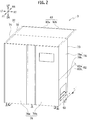
- Fig. 2 is a front perspective view of the printing apparatus 3.
- Fig. 3 is a rear perspective view of the printing apparatus 3.
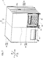
- Fig. 4 is a perspective view of a state where front doors 76a and 76b of the printing apparatus 3 are opened.
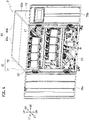
- Fig. 5 is a perspective view of a state where rear doors 83a and 83b of the printing apparatus 3 are opened.
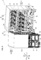
- Fig. 6 is a perspective view of a state where a space is opened between a main body housing 71 and an electric component housing 72 of the printing apparatus 3 and a side cover 81b in a lower portion of a left face 81 of the electric component housing 72 is removed.
- Fig. 1 is a schematic configuration diagram of a printing system 1 including a printing apparatus 3 in an embodiment of the present invention.
- Fig. 2 is a front perspective view of the printing apparatus 3.
- Fig. 3
- FIG. 7 is a perspective view of a state where a side cover 82b in a lower portion of a right face 82 of the electric component housing 72 in the printing apparatus 3 is removed.
- Fig. 8 is a schematic view for explaining an arrangement of units in a lower portion of the electric component housing 72 in the printing apparatus 3.
- RT right, left, up, down, front, and rear are denoted by RT, LT, UP, DN, FT, and RR, respectively.
- the printing system 1 includes a wind-off apparatus 2, the printing apparatus 3, and a wind-up apparatus 4.
- the wind-off apparatus 2 winds off a web W being a long print medium made of film, paper, or the like to the printing apparatus 3.
- the wind-off apparatus 2 includes a web roll support shaft 11, a brake 12, and a wind-off apparatus controller 13.
- the web roll support shaft 11 rotatably supports a web roll 16.
- the web roll support shaft 11 is formed in a long shape extending in a front-rear direction.
- the web roll 16 is a roll of the web W.
- the brake 12 applies brake to the web roll support shaft 11. Tension is thereby applied to the web W between the web roll 16 and a pair of conveyance rollers 54 of the printing apparatus 3 to be described later.
- the wind-off apparatus controller 13 controls brake force of the brake 12 to adjust the tension applied to the web W.
- the wind-off apparatus controller 13 includes a CPU, a RAM, a ROM, a hard disk, and the like.
- the printing apparatus 3 prints images on the web W wound off from the wind-off apparatus 2 while conveying the web W.
- the printing apparatus 3 includes a conveyor 21, a first printer 22, a second printer 23, an ink circulator 24, a waste liquid storage 25, a conveyance controller 26, a meandering correction controller 27, a head controller 28, an ink circulation controller 29, a power supply unit 30, a breaker 31, and a housing 32.
- the conveyor 21 conveys the web W wound off from the wind-off apparatus 2.
- the conveyor 21 includes guide rollers 41 to 50, twenty under-head support members 51, a meandering corrector 52, an encoder 53, the pair of conveyance rollers 54, and a conveyance motor 55.
- the guide rollers 41 to 50 guide the web W conveyed in the printing apparatus 3.
- the guide rollers 41 to 50 rotate by following the conveyed web W.
- the guide rollers 41 to 50 are formed in a long shape extending in the front-rear direction.
- the guide rollers 41 and 42 guide the web W between the wind-off apparatus 2 and the meandering corrector 52.
- the guide roller 41 is arranged near a left face of the housing 32 in a lower portion of the printing apparatus 3.
- the guide roller 42 is arranged between the guide roller 41 and a meandering correction roller 56A of the meandering corrector 52 to be described later.
- the guide rollers 43 to 49 guide the web W between the meandering corrector 52 and the pair of conveyance rollers 54.
- the guide roller 43 is arranged on the left of a meandering correction roller 56B of the meandering corrector 52 to be described later.
- the guide roller 44 is arranged above the guide roller 43.
- the guide roller 45 is arranged on the right of the guide roller 44 at the same height as the guide roller 44.
- the guide roller 46 is arranged below the guide roller 45 and above the guide roller 43.
- the guide roller 47 is arranged on the left of the guide roller 46, near and on the right of the web W between the guide rollers 43 and 44, at substantially the same height as the guide roller 46.
- the guide roller 48 is arranged on the lower right side of the guide roller 47.
- the guide roller 49 is arranged below and slightly on the right of the guide roller 48.
- the guide roller 50 guides the web W between the pair of conveyance rollers 54 and the wind-up apparatus 4.
- the guide roller 50 is arranged near a right face of the housing 32 in the lower portion of the printing apparatus 3.
- the under-head support members 51 support the web W under the first printer 22 and the second printer 23.
- the under-head support members 51 are formed in a long shape extending in the front-rear direction.
- Ten under-head support members 51 are arranged in each of an area between the guide rollers 44 and 45 which is under the first printer 22 and an area between the guide rollers 46 and 47 which is under the second printer 23.
- the ten under-head support members 51 in each of the area between the guide rollers 44 and 45 and the area between the guide rollers 46 and 47 are arranged in an arch shape protruding upward.
- the web W is thereby tensioned and maintained in a stable position between the guide rollers 44 and 45 and between the guide rollers 46 and 47.
- the meandering corrector 52 corrects meandering of the web W.
- the meandering corrector 52 includes the meandering correction rollers 56A and 56B, a meandering correction motor 57, and a web sensor 58.
- the meandering correction rollers 56A and 56B are rollers for guiding the web W and correcting the meandering of the web W.
- the meandering correction rollers 56A and 56B are formed in a long shape extending in the front-rear direction.
- the meandering correction rollers 56A and 56B are each configured such that the angle of the axial direction of the meandering correction roller to the front-rear direction on a horizontal plane can be adjusted.
- the meandering correction roller 56A is arranged on the right of the guide roller 42.
- the meandering correction roller 56B is arranged above the meandering correction roller 56A.
- the meandering correction motor 57 turns the meandering correction rollers 56A and 56B about an axis orthogonal to the horizontal plane to adjust the angles of axial directions of the meandering correction rollers 56A and 56B to the front-rear direction on the horizontal plane.
- the web sensor 58 detects the positions of edges of the web W in the front-rear direction to correct the meandering.
- the web sensor 58 is arranged near the meandering correction roller 56B.
- the encoder 53 is connected to the guide roller 44 and outputs a pulse signal every time the guide roller 44 rotates by a predetermined angle.
- the pulse signal outputted from the encoder 53 is used to control conveyance speed of the web W.
- the pair of conveyance rollers 54 convey the web W toward the wind-up apparatus 4 while nipping the web W.
- the pair of conveyance rollers 54 are arranged between the guide rollers 49 and 50.
- the conveyance motor 55 rotationally drives the conveyance rollers 54.
- the first printer 22 prints images on a front side of the web W.
- the first printer 22 is arranged above the web W between the guide rollers 44 and 45.
- the first printer 22 includes five head units 61.
- the head units 61 include inkjet heads (not illustrated) and eject inks from nozzles of the inkjet heads.
- the five head units 61 of the first printer 22 eject inks of different colors, respectively.
- the second printer 23 prints images on a back side of the web W.
- the second printer 23 is arranged above the web W between the guide rollers 46 and 47.
- the second printer 23 includes five head units 61 configured to eject inks of different colors, respectively, like the first printer 22.
- the ink circulator 24 supplies the inks to the inkjet heads of the head units 61 while circulating the inks along ink circulation routes.
- the ink circulator 24 includes the ink circulation route, an ink cartridge configured to supply the ink to the ink circulation route, and the like for each of the head units 61.
- An ink tank configured to store the supplied ink, an ink pump configured to feed the ink for the circulation of the ink, and the like are provided in each of the ink circulation routes .
- the ink circulator 24 also includes a drive board configured to drive the ink pumps and the like.
- the waste liquid storage 25 stores the inks discharged in cleaning of the inkjet heads in the head units 61 as waste liquid. As illustrated in Fig. 5 , multiple waste liquid tanks 66 are provided in the printing apparatus 3 for the inks of the respective colors in the first and second printers 22 and 23.
- the conveyance controller 26 controls drive of the conveyance motor 55.
- the conveyance controller 26 includes a CPU, a RAM, a ROM, a hard disk, and the like.
- the meandering correction controller 27 controls drive of the meandering correction motor 57.
- the meandering correction controller 27 includes a CPU, a RAM, a ROM, a hard disk, and the like.
- the head controller 28 includes multiple head control units 67 as illustrated in Fig. 5 .
- the head control units 67 control drive of the inkjet heads in the head units 61.
- the head control units 67 each include a CPU, a RAM, a ROM, a hard disk, and the like.
- the ink circulation controller 29 includes multiple ink circulation control units 68 as illustrated in Fig. 7 .
- the ink circulation control units 68 control drive of the pumps and the like of the ink circulator 24.
- the ink circulation control units 68 each include a CPU, a RAM, a ROM, a hard disk, and the like.
- the power supply unit 30 is a unit configured to supply power supplied from the mains to the units of the printing apparatus 3.
- the breaker 31 is a unit configured to cut the power supply to the printing apparatus 3 when a current exceeding an allowable current flows.
- the housing 32 houses multiple components of the printing apparatus 3 except for the housing 32. Specifically, the housing 32 houses the conveyor 21, the first printer 22, the second printer 23, the ink circulator 24, the waste liquid storage 25, the conveyance controller 26, the meandering correction controller 27, the head controller 28, the ink circulation controller 29, the power supply unit 30, and the breaker 31. The housing 32 also houses wires connecting the units and the like.
- the housing 32 is divided into the main body housing 71 and the electric component housing 72 in the front-rear direction.
- the main body housing 71 and the electric component housing 72 are connected to each other and configured to be closeable and openable in the horizontal direction at a center opening-closing portion (opening-closing portion) 73 which is a boundary portion between the main body housing 71 and the electric component housing 72.
- the main body housing 71 and the electric component housing 72 correspond to divided housings.
- the main body housing 71 houses the conveyor 21, the first printer 22, and the second printer 23.
- the main body housing 71 is formed in a hollow rectangular solid shape.
- a front face 76 of the main body housing 71 is configured to be closeable and openable by the front doors 76a and 76b.
- a left face 77 of the main body housing 71 is formed of side covers 77a and 77b detachably attached by screws.
- a right face 78 of the main body housing 71 is formed of side covers 78a and 78b detachably attached by screws.
- a rear side of the main body housing 71 is open and an opening portion 79 is formed.
- the electric component housing 72 houses the ink circulator 24, the waste liquid storage 25, the conveyance controller 26, the meandering correction controller 27, the head controller 28, the ink circulation controller 29, the power supply unit 30, and the breaker 31.
- the electric component housing 72 is arranged behind the main body housing 71.
- the electric component housing 72 is formed in a hollow rectangular solid shape with the same height and width as the main body housing 71.
- the electric component housing 72 is open on the front side and an opening portion 80 is formed.
- the left face 81 of the electric component housing 72 is formed of side covers 81a and 81b detachably attached by screws .
- the right face 82 of the electric component housing 72 is formed of side covers 82a and 82b detachably attached by screws.
- a rear face 83 of the electric component housing 72 is configured to be openable and closeable by the rear doors 83a and 83b.
- the front face 76 of the main body housing 71, the left face 77 of the main body housing 71, the right face 78 of the main body housing 71, the left face 81 of the electric component housing 72, the right face 82 of the electric component housing 72, the rear face 83 of the electric component housing 72, and the center opening-closing portion 73 are access portions used by a user and a service man to access the inside of the housing 32.
- the front face 76 of the main body housing 71 corresponds to the front face of the housing 32.
- the left face 77 of the main body housing 71, the right face 78 of the main body housing 71, the left face 81 of the electric component housing 72, and the right face 82 of the electric component housing 72 correspond to the side faces of the housing 32.
- the rear face 83 of the electric component housing 72 corresponds to the rear face of the housing 32.
- the wind-up apparatus 4 winds up the web W subjected to printing in the printing apparatus 3.
- the wind-up apparatus 4 includes a wind-up shaft 91, a wind-up motor 92, and a wind-up apparatus controller 93.
- the wind-up shaft 91 winds up and holds the web W.
- the wind-up shaft 91 is formed in a long shape extending in the front-rear direction.
- the wind-up motor 92 rotates the wind-up shaft 91 clockwise in Fig. 1 .
- the wind-up shaft 91 winds up the web W by being rotated.
- the wind-up apparatus controller 93 controls drive of the wind-up motor 92.
- the wind-up apparatus controller 93 includes a CPU, a RAM, a ROM, a hard disk, and the like.
- components to be accessed by at least the user or the service man are arranged based on the position and difficulty level of access of each of the access portions in the housing 32 and on frequency of access to each of the components by the user and the service man.
- the user is a person (general user) who uses the printing apparatus 3 on a daily basis
- the service man is a person who performs maintenance and the like on the printing apparatus 3 as appropriate.
- the difficulty level of access of each access portion in the housing 32 is predetermined based on a difficulty level of work of accessing the inside of the housing 32 from this access portion.
- the difficulty level of access of each access portion in the housing 32 is set to one of four levels of A to D which are in the descending order of difficulty of access.
- An access portion with the difficulty level of access of D from which the inside of the housing 32 can be most easily accessed is the front face 76 of the main body housing 71. Since the inside of the housing 32 can be accessed from the front face 76 of the main body housing 71 only by opening the front doors 76a and 76b, the difficulty level of access of the front face 76 is the lowest.
- An access portion with the difficulty level of access of C is the rear face 83 of the electric component housing 72.
- the user or the service man has to go behind the printing apparatus 3 and open the rear doors 83a and 83b. Accordingly, the difficulty level of access of the rear face 83 of the electric component housing 72 is set higher than that of the front face 76 of the main body housing 71.
- Access portions with the difficulty level of access of B are the left face 77 of the main body housing 71, the right face 78 of the main body housing 71, the left face 81 of the electric component housing 72, and the right face 82 of the electric component housing 72.
- the side covers 77a, 77b, 78a, 78b, 81a, 81b, 82a, and 82b fixed by screws have to be removed. Accordingly, the difficulty level of access of these side faces are set higher than difficulty levels of access of the front face 76 of the main body housing 71 and the rear face 83 of the electric component housing 72.
- An access portion with the difficulty level of access of A is the center opening-closing portion 73.
- the difficulty level of access of the center opening-closing portion 73 is set higher than those of the other access portions.
- a component which needs to be accessed by the user and whose frequency of access by the user is high is arranged at a position suitable for access from the front face 76 of the main body housing 71 with the difficulty level of access of D, regardless of the frequency of access by the service man.
- the conveyor 21, the first printer 22, and the second printer 23 are arranged in the main body housing 71 at suitable positions which can be accessed by opening the front doors 76a and 76b of the main body housing 71.
- the user accesses the conveyor 21, the first printer 22, and the second printer 23 upon setting the web W. Specifically, the user pushes the head units 61 of the first and second printers 22 and 23 rearward. Then, the user sets the web W along a conveyance route formed by the guide rollers 41 to 50, the meandering correction rollers 56A and 56B, the under-head support members 51, and the conveyance rollers 54. Moreover, the user adjusts the position of the web sensor 58 depending on the width of the set web W.
- a component which needs to be accessed by the user but whose frequency of access by the user is low is arranged at a position suitable for access from the rear face 83 of the electric component housing 72 with the difficulty level of access of C, regardless of the frequency of access by the service man.
- a component which is not an access target of the user and is thus not accessed by the user but whose frequency of access by the service main is high is also arranged at a position suitable for access from the rear face 83 of the electric component housing 72 with the difficulty level of access of C.
- the waste liquid storage 25, the conveyance controller 26, the meandering correction controller 27, the head controller 28, and the breaker 31 are arranged at suitable positions which can be accessed by opening the rear doors 83a and 83b of the electric component housing 72.
- the waste liquid storage 25, the conveyance controller 26, the meandering correction controller 27, the head controller 28, and the breaker 31 are arranged in a rear interior portion of the electric component housing 72.
- the user accesses the waste liquid storage 25 to discard the waste liquid when any of the waste liquid tanks 66 is full.
- the user accesses the conveyance controller 26 to change the conveyance speed of the web W by the conveyance rollers 54.
- the user accesses the meandering correction controller 27 to adjust parameters such as response speed, adjustment amount, and the like of the meandering corrector 52.
- the user accesses the breaker 31 to turn on the breaker 31 when it is turned off. The user needs to access the waste liquid storage 25, the conveyance controller 26, the meandering correction controller 27, and the breaker 31.
- the head controller 28 is accessed for an ink ejection test and the like of the inkjet heads of the head units 61.
- the service man accesses the head controller 28, and the user does not.
- a component which is not an access target of the user and is thus not accessed by the user and whose frequency of access by the service main is a medium level is arranged at a position suitable for access from any of the left face 77 of the main body housing 71, the right face 78 of the main body housing 71, the left face 81 of the electric component housing 72, and the right face 82 of the electric component housing 72 with the difficulty level of access of B.
- the ink circulation controller 29 is arranged at a suitable position which can be accessed by removing the side cover 82b in the lower portion of the right face 82 of the electric component housing 72.
- the ink circulation controller 29 is arranged in a right end portion of a lower interior portion of the electric component housing 72.
- the wires (not illustrated) of the power supply unit 30 are arranged at suitable positions which can be accessed by removing the side cover 81b in the lower portion of the left face 81 of the electric component housing 72.
- the wires of the power supply unit 30 are arranged in a left end portion of the lower interior portion of the electric component housing 72.
- a component which is not an access target of the user and is thus not accessed by the user and whose frequency of access by the service main is low is arranged at a position suitable for access from the center opening-closing portion 73 with the difficulty level of access of A.
- access from the center opening-closing portion 73 is performed from the opening portion 79 on the rear side of the main body housing 71 or the opening portion 80 on the front side of the electric component housing 72 by opening a space between the main body housing 71 and the electric component housing 72 at the center opening-closing portion 73. Accessing the space opened between the main body housing 71 and the electric component housing 72 is also included in the access from the center opening-closing portion 73.
- the power supply unit 30 is arranged at a position suitable for access from the opening portion 80 on the front side of the electric component housing 72.
- the power supply unit 30 is arranged in a front interior portion of the electric component housing 72. The service man accesses the power supply unit 30 to detach and attach the power supply unit 30.
- the ink pumps and the drive board of the ink circulator 24 are arranged in a region S illustrated in Fig. 8 which is at a position suitable for access from the opening portion 80 on the front side of the electric component housing 72.
- the ink pumps and the drive board of the ink circulator 24 are arranged in the front interior portion of the electric component housing 72.
- the service man accesses the ink pumps for repair and the like.
- the drive board for repair and the like.
- wires 86 between the main body housing 71 and the electric component housing 72 are laid at positions which can be suitably accessed from the opening portion 79 on the rear side of the main body housing 71, the opening portion 80 on the front side of the electric component housing 72, and the space between main body housing 71 and the electric component housing 72.
- the wires 86 include wires for electrically connecting the components in the main body housing 71 and the components in the electric component housing 72 in the printing apparatus 3 and pipes forming the ink circulation routes of the ink circulator 24. For example, when the components in the housing 32 of the printing apparatus 3 are to be replaced, the service man accesses the wires 86 to perform rewiring.
- the wind-off apparatus 2 When the printing is performed in the printing system 1, first, the wind-off apparatus 2, the printing apparatus 3, and the wind-up apparatus 4 start conveyance of the web W. Specifically, the wind-off apparatus controller 13 activates the brake 12, the conveyance controller 26 of the printing apparatus 3 starts the drive of the conveyance motor 55, and the wind-up apparatus controller 93 starts the drive of the wind-up motor 92. This causes the web W to be conveyed from the wind-off apparatus 2 to the wind-up apparatus 4. Applying brake to the web roll support shaft 11 with the brake 12 of the wind-off apparatus 2 causes the web W to be conveyed with tension applied to the web W between the web roll 16 and the conveyance rollers 54.
- the ink circulation controller 29 of the printing apparatus 3 starts an ink circulation operation by the ink circulator 24.
- the head controller 28 of the printing apparatus 3 controls the inkjet heads of the head units 61 in the first and second printers 22 and 23 to print images on the web W.
- the conveyance controller 26 of the printing apparatus 3 calculates the conveyance speed of the web W based on the pulse signal outputted from the encoder 53. Then, the conveyance controller 26 controls the current to be supplied to the conveyance motor 55 such that the difference between the calculated conveyance speed and print conveyance speed (target speed) becomes zero. The conveyance speed of the web W is thereby controlled to be constant.
- the conveyance controller 26 calculates output torque of the conveyance motor 55 corresponding to the current supplied to the conveyance motor 55.
- the value of the output torque of the conveyance motor 55 corresponding to the supplied current can be calculated from motor characteristics of the conveyance motor 55.
- the wind-off apparatus controller 13 adjusts the brake force (output torque) of the brake 12 such that the difference between the output torque of the brake 12 and the output torque of the conveyance motor 55 calculated by the conveyance controller 26 becomes a target torque difference corresponding to target tension of the web W.
- the tension of the web W is thereby controlled to be constant.
- the ink circulation controller 29 of the printing apparatus 3 terminates the ink circulation operation by the ink circulator 24.
- the wind-off apparatus 2, the printing apparatus 3, and the wind-up apparatus 4 terminate the conveyance of the web W.
- the wind-off apparatus controller 13 stops the brake 12
- the conveyance controller 26 of the printing apparatus 3 stops the conveyance motor 55
- the wind-up apparatus controller 93 stops the wind-up motor 92. The series of operations is thereby completed.
- the components to be accessed by at least the user or the service man are arranged based on the position and difficulty level of access of each access portion in the housing 32 and on the frequency of access to each component by the user and the service man. This can reduce occurrence of a situation where a component of the printing apparatus 3 to be accessed by the user and the service man is arranged at a position difficult to access . As a result, the convenience in cases where the user and the service man access the components in the housing 32 of the printing apparatus 3 can be improved.
- the components which need to be accessed by the user are arranged at positions suitable for access from the front face 76 of the main body housing 71 or the rear face 83 of the electric component housing 72 with the low difficulty level of access, depending on the difficulty levels of access of the access portions and the frequency of access to these components by the user.
- the user can thereby easily access the components which need to be accessed, and the convenience for the user is thus improved.
- the components which need to be accessed by the service man and which are not the access targets of the user are arranged at positions suitable for access from the access portions other than the front face 76 of the main body housing 71 with the lowest difficulty level of access, depending on the difficulty levels of access of the access portions and the frequency of access to the components by the service man. Accordingly, it is possible to suppress unnecessary access to these components by the user while improving the convenience for the service man.
- the printing apparatus 3 can suppress unnecessary access to the components in the housing 32 of the printing apparatus 3 while improving the convenience in cases where the user and the service access the components.
- the components arranged based on the positions and difficulty levels of access of the access portions in the housing 32 and the frequency of access to the components by the user and the service man may be some of the components to be accessed by at least the user or the service man.
- the printing apparatus only needs to be such that at least some of multiple components (components for achieving the functions of the printing apparatus 3) of the apparatus housed in the housing are arranged based on the positions and difficulty levels of access of the access portions and the frequency of access to the components by the user and the service man.
- which components of the printing apparatus 3 are to be arranged for each of the access portions with the difficulty levels of access of A to D are determined from the general frequency of access to each of the components of the printing apparatus 3 by the user and the service man.
- the printing apparatus 3 may be configured such that, for example, frequency of access to each of the components of the printing apparatus 3 by the user and service man is obtained through experiments, and which components of the printing apparatus 3 are to be arranged for each of the access portions with the difficulty levels of access of A to D are determined based on the obtained frequency.
- the printing apparatus 3 which performs printing on the web by using an inkjet method
- the printing apparatus may be one using a different printing method and a different print medium.
Description
- The present invention relates to a printing apparatus including a housing.
- A housing of a printing apparatus is provided with a door and the like which a person such as a user uses to access components of the printing apparatus housed in the housing in various operations, maintenance, and the like.
- In a printing apparatus of Japanese Unexamined Patent Application Publication No.
2004-130578 -
US 9,302,516 B2 -
US 6,280,018 B1 discloses a shuttle system transferring an ink-jet pen between a carriage and a shuttle access location on a printer front panel. When a pen load button is pushed, the shuttle will move to an access position. In the access position, the shuttle will open a door and come beyond the front face of the printer. This allows the user to drop the pen(s) into place on the shuttle. Then when the button is pushed again, the pen shuttle will transfer the pens back into the printer, with the door closing, and automatically loads the pen(s) into the printer carriage without manual user intervention. The pen shuttle will then move to a rest position for normal printer operation. If the pen load button is pressed again, the pen shuttle moves back to the carriage and unloads the pen(s) automatically. The pen shuttle again opens the access door and presents the pens to the user. The shuttle has pen wipers and capping structures mounted for movement with the shuttle, allowing for pen service functions to be performed without the need for an additional service station. -
US 2008/0094987 A1 discloses a media storage which is adapted to store a plate-shaped medium. A media drive is operable to write data in the medium. A label printer is operable to print on the medium. A media conveyer is operable to convey the medium between the media storage, the media drive and the label printer. A casing defines an interior space of the media processor. A plateshaped frame divides the interior space into a first space located in a rear upper portion of the interior space, a second space located in a rear lower portion of the interior space and a front space located in a front portion of the interior space. The media drive is disposed in the first space. The label printer is disposed in the second space. The media storage and the media conveyer are disposed in the front space. -
JP 2004 130 578 A -
US 2009/0274342 A1 discloses a method for automated image quality based diagnosis of a document printing system. The method comprises receiving image data to be printed on a document; printing an image on the document based on the image data; scanning the printed image on the document with a sensor; analyzing the scanned printed image with an image quality analysis module to identify one or more defects in the printed image; automatically generating test pattern image data based on the one or more identified defects; and printing and analysing a test pattern image based on the test pattern image data. -
EP 2 487 041 A2 -
US 2012/0293583 A1 discloses an image forming apparatus which includes a main body and a printing assembly. The printing assembly includes a carriage, an encoder scale, an encoder sensor, and a flexible cable. The carriage has a head mounting part and a board mounting part arranged along a direction perpendicular to the main scanning direction. The head mounting part mounts a recording head. The board mounting part mounts both the sensor and a carriage- side circuit board connected to the cable. A housing of the body has a first cover portion to cover an area opposing the head mounting part and a second cover portion to cover an area opposing the board mounting part. The first cover portion is openably disposed at the body to allow a user to open the first cover portion. The second cover portion is stationarily fixed at the body to prevent a user from opening the second cover portion. -
US 2015/0258800 A1 discloses a recording apparatus including a recording head that can eject an ink onto a sheet, a transport unit that transports the sheet to the recording head, a housing that contains the recording head and the transport unit, a case that is arranged on an outer surface of the housing so that the bottom portion thereof is positioned higher than a bottom surface of the housing, and that serves as a holder which holds an ink container containing an ink, and a supply unit that supplies the ink from the ink container to the recording head. - In the printing apparatus described above, the user has to open the front door and the partition door to access the parts in the drive system area. Accordingly, the parts in the drive system area are more troublesome for the user to access than the parts in the control area which can be accessed by just opening the operation panel and the parts in the ink area which can be accessed by just opening the front door.
- As described above, the components in the housing of the printing apparatus sometimes vary in accessibility depending on the positions thereof.
- The user and a service man who performs maintenance and the like of the printing apparatus are main persons who access the components in the housing of the printing apparatus. Meanwhile, in general, not all of the components are accessed evenly at the same frequency by either of the user and the service man.
- Accordingly, there may be a case where specific components to be accessed frequently by the user and service man, respectively, are arranged at positions with low accessibility. Hence, depending on the arrangement of the components in the housing, the convenience of the printing apparatus may be decreased in terms of the accesses to the components.
- An object of the present invention is to provide a printing apparatus improved in convenience in cases where a user and a service man access components in a housing of the printing apparatus.
- A printing apparatus in accordance with the present invention is defined by
claim 1. Dependent claims relate to preferred embodiments. - With the printing apparatus according to the present invention, it is possible to reduce occurrence of a situation where the components of the printing apparatus to be accessed by the user and the service man are arranged at positions with low accessibility. As a result, the convenience in cases where the user and the service man access the components in the housing of the printing apparatus can be improved.
- The housing includes two divided housings divided in a front-rear direction of the printing apparatus. The plurality of access portions may include a front face of the housing, a rear face of the housing, a side face of the housing, and an opening-closing portion between the two divided housings. The predetermined difficulty levels of access of the access portions may decrease in an order of the opening-closing portion, the side face, the rear face, and the front face. A first component of the plurality of components necessary for the user to access may be arranged at a position suitable for access from the front face or a position suitable for access from the rear face, depending on the difficulty levels of access of the front face and the rear face and the frequency of access to the first component by the user. A second component of the plurality of components necessary for the service man to access and not being an access target of the user may be arranged at any of a position suitable for access from the rear face, a position suitable for access from the side face, and a position suitable for access from the opening-closing portion, depending on the difficulty levels of access of the rear face, the side face, and the opening-closing portion and the frequency of access to the second component by the service man.
- In the configuration described above, the component which needs to be accessed by the user is arranged at the position suitable for access from the front face or the rear face of the housing with low difficulty levels of access, depending on the difficulty levels of access of these access portions and the frequency of access to the component by the user. The user can thereby easily access the component which needs to be accessed, and the convenience for the user is thus improved. Moreover, the component which needs to be accessed by the service man and which is not the access target of the user is arranged at any of positions suitable for access from access portions other than the front face of the housing with the lowest difficulty level of access, depending on the difficulty levels of access of the access portions and the frequency of access to the component by the service man. Accordingly, it is possible to suppress unnecessary access to the components by the user while improving the convenience for the service man. Hence, the configuration described above can suppress unnecessary access to the components in the housing of the printing apparatus while improving the convenience in cases where the user and the service access the components.
-
-
Fig. 1 is a schematic configuration diagram of a printing system in an embodiment. -
Fig. 2 is a front perspective view of a printing apparatus in the embodiment. -
Fig. 3 is a rear perspective view of the printing apparatus in the embodiment. -
Fig. 4 is a perspective view of a state where front doors of the printing apparatus in the embodiment are opened. -
Fig. 5 is a perspective view of a state where rear doors of the printing apparatus in the embodiment are opened. -
Fig. 6 is a perspective view of a state where a space is opened between a main body housing and an electric component housing of the printing apparatus in the embodiment and a side cover in a lower portion of a left face of the electric component housing is removed. -
Fig. 7 is a perspective view of a state where a side cover in a lower portion of a right face of the electric component housing is removed in the printing apparatus in the embodiment. -
Fig. 8 is a schematic view for explaining an arrangement of units in a lower portion of the electric component housing in the printing apparatus in the embodiment. - In the following detailed description, for purposes of explanation, numerous specific details are set forth in order to provide a thorough understanding of the disclosed embodiments. It will be apparent, however, that one or more embodiments may be practiced without these specific details. In other instances, well-known structures and devices are schematically shown in order to simplify the drawing.
- Description will be hereinbelow provided for embodiments of the present invention by referring to the drawings. It should be noted that the same or similar parts and components throughout the drawings will be denoted by the same or similar reference signs, and that descriptions for such parts and components will be omitted or simplified. In addition, it should be noted that the drawings are schematic and therefore different from the actual ones.
-
Fig. 1 is a schematic configuration diagram of aprinting system 1 including aprinting apparatus 3 in an embodiment of the present invention.Fig. 2 is a front perspective view of theprinting apparatus 3.Fig. 3 is a rear perspective view of theprinting apparatus 3.Fig. 4 is a perspective view of a state wherefront doors printing apparatus 3 are opened.Fig. 5 is a perspective view of a state whererear doors printing apparatus 3 are opened.Fig. 6 is a perspective view of a state where a space is opened between amain body housing 71 and anelectric component housing 72 of theprinting apparatus 3 and aside cover 81b in a lower portion of aleft face 81 of theelectric component housing 72 is removed.Fig. 7 is a perspective view of a state where aside cover 82b in a lower portion of aright face 82 of theelectric component housing 72 in theprinting apparatus 3 is removed.Fig. 8 is a schematic view for explaining an arrangement of units in a lower portion of theelectric component housing 72 in theprinting apparatus 3. InFigs. 1 to 8 , right, left, up, down, front, and rear are denoted by RT, LT, UP, DN, FT, and RR, respectively. - As illustrated in
Fig. 1 , theprinting system 1 includes a wind-off apparatus 2, theprinting apparatus 3, and a wind-upapparatus 4. - The wind-
off apparatus 2 winds off a web W being a long print medium made of film, paper, or the like to theprinting apparatus 3. The wind-off apparatus 2 includes a webroll support shaft 11, abrake 12, and a wind-off apparatus controller 13. - The web
roll support shaft 11 rotatably supports aweb roll 16. The webroll support shaft 11 is formed in a long shape extending in a front-rear direction. Theweb roll 16 is a roll of the web W. - The
brake 12 applies brake to the webroll support shaft 11. Tension is thereby applied to the web W between theweb roll 16 and a pair ofconveyance rollers 54 of theprinting apparatus 3 to be described later. - The wind-
off apparatus controller 13 controls brake force of thebrake 12 to adjust the tension applied to the web W. The wind-off apparatus controller 13 includes a CPU, a RAM, a ROM, a hard disk, and the like. - The
printing apparatus 3 prints images on the web W wound off from the wind-off apparatus 2 while conveying the web W. Theprinting apparatus 3 includes aconveyor 21, afirst printer 22, asecond printer 23, anink circulator 24, awaste liquid storage 25, aconveyance controller 26, ameandering correction controller 27, ahead controller 28, anink circulation controller 29, apower supply unit 30, abreaker 31, and ahousing 32. - The
conveyor 21 conveys the web W wound off from the wind-off apparatus 2. Theconveyor 21 includesguide rollers 41 to 50, twenty under-head support members 51, a meanderingcorrector 52, anencoder 53, the pair ofconveyance rollers 54, and aconveyance motor 55. - The
guide rollers 41 to 50 guide the web W conveyed in theprinting apparatus 3. Theguide rollers 41 to 50 rotate by following the conveyed web W. Theguide rollers 41 to 50 are formed in a long shape extending in the front-rear direction. - The
guide rollers off apparatus 2 and the meanderingcorrector 52. Theguide roller 41 is arranged near a left face of thehousing 32 in a lower portion of theprinting apparatus 3. Theguide roller 42 is arranged between theguide roller 41 and ameandering correction roller 56A of the meanderingcorrector 52 to be described later. - The
guide rollers 43 to 49 guide the web W between the meanderingcorrector 52 and the pair ofconveyance rollers 54. Theguide roller 43 is arranged on the left of ameandering correction roller 56B of the meanderingcorrector 52 to be described later. Theguide roller 44 is arranged above theguide roller 43. Theguide roller 45 is arranged on the right of theguide roller 44 at the same height as theguide roller 44. Theguide roller 46 is arranged below theguide roller 45 and above theguide roller 43. Theguide roller 47 is arranged on the left of theguide roller 46, near and on the right of the web W between theguide rollers guide roller 46. Theguide roller 48 is arranged on the lower right side of theguide roller 47. Theguide roller 49 is arranged below and slightly on the right of theguide roller 48. - The
guide roller 50 guides the web W between the pair ofconveyance rollers 54 and the wind-upapparatus 4. Theguide roller 50 is arranged near a right face of thehousing 32 in the lower portion of theprinting apparatus 3. - The under-
head support members 51 support the web W under thefirst printer 22 and thesecond printer 23. The under-head support members 51 are formed in a long shape extending in the front-rear direction. Ten under-head support members 51 are arranged in each of an area between theguide rollers first printer 22 and an area between theguide rollers second printer 23. - The ten under-
head support members 51 in each of the area between theguide rollers guide rollers guide rollers guide rollers - The meandering
corrector 52 corrects meandering of the web W. The meanderingcorrector 52 includes themeandering correction rollers meandering correction motor 57, and aweb sensor 58. - The
meandering correction rollers meandering correction rollers meandering correction rollers meandering correction roller 56A is arranged on the right of theguide roller 42. Themeandering correction roller 56B is arranged above the meanderingcorrection roller 56A. - The
meandering correction motor 57 turns themeandering correction rollers meandering correction rollers - The
web sensor 58 detects the positions of edges of the web W in the front-rear direction to correct the meandering. Theweb sensor 58 is arranged near themeandering correction roller 56B. - The
encoder 53 is connected to theguide roller 44 and outputs a pulse signal every time theguide roller 44 rotates by a predetermined angle. The pulse signal outputted from theencoder 53 is used to control conveyance speed of the web W. - The pair of
conveyance rollers 54 convey the web W toward the wind-upapparatus 4 while nipping the web W. The pair ofconveyance rollers 54 are arranged between theguide rollers - The
conveyance motor 55 rotationally drives theconveyance rollers 54. - The
first printer 22 prints images on a front side of the web W. Thefirst printer 22 is arranged above the web W between theguide rollers first printer 22 includes fivehead units 61. - The
head units 61 include inkjet heads (not illustrated) and eject inks from nozzles of the inkjet heads. The fivehead units 61 of thefirst printer 22 eject inks of different colors, respectively. - The
second printer 23 prints images on a back side of the web W. Thesecond printer 23 is arranged above the web W between theguide rollers second printer 23 includes fivehead units 61 configured to eject inks of different colors, respectively, like thefirst printer 22. - The
ink circulator 24 supplies the inks to the inkjet heads of thehead units 61 while circulating the inks along ink circulation routes. Theink circulator 24 includes the ink circulation route, an ink cartridge configured to supply the ink to the ink circulation route, and the like for each of thehead units 61. An ink tank configured to store the supplied ink, an ink pump configured to feed the ink for the circulation of the ink, and the like are provided in each of the ink circulation routes . Theink circulator 24 also includes a drive board configured to drive the ink pumps and the like. - The
waste liquid storage 25 stores the inks discharged in cleaning of the inkjet heads in thehead units 61 as waste liquid. As illustrated inFig. 5 , multiplewaste liquid tanks 66 are provided in theprinting apparatus 3 for the inks of the respective colors in the first andsecond printers - The
conveyance controller 26 controls drive of theconveyance motor 55. Theconveyance controller 26 includes a CPU, a RAM, a ROM, a hard disk, and the like. - The
meandering correction controller 27 controls drive of themeandering correction motor 57. Themeandering correction controller 27 includes a CPU, a RAM, a ROM, a hard disk, and the like. - The
head controller 28 includes multiplehead control units 67 as illustrated inFig. 5 . Thehead control units 67 control drive of the inkjet heads in thehead units 61. Thehead control units 67 each include a CPU, a RAM, a ROM, a hard disk, and the like. - The
ink circulation controller 29 includes multiple inkcirculation control units 68 as illustrated inFig. 7 . The inkcirculation control units 68 control drive of the pumps and the like of theink circulator 24. The inkcirculation control units 68 each include a CPU, a RAM, a ROM, a hard disk, and the like. - The
power supply unit 30 is a unit configured to supply power supplied from the mains to the units of theprinting apparatus 3. - The
breaker 31 is a unit configured to cut the power supply to theprinting apparatus 3 when a current exceeding an allowable current flows. - The
housing 32 houses multiple components of theprinting apparatus 3 except for thehousing 32. Specifically, thehousing 32 houses theconveyor 21, thefirst printer 22, thesecond printer 23, theink circulator 24, thewaste liquid storage 25, theconveyance controller 26, the meanderingcorrection controller 27, thehead controller 28, theink circulation controller 29, thepower supply unit 30, and thebreaker 31. Thehousing 32 also houses wires connecting the units and the like. - As illustrated in
Figs. 2 to 7 , thehousing 32 is divided into themain body housing 71 and theelectric component housing 72 in the front-rear direction. Themain body housing 71 and theelectric component housing 72 are connected to each other and configured to be closeable and openable in the horizontal direction at a center opening-closing portion (opening-closing portion) 73 which is a boundary portion between themain body housing 71 and theelectric component housing 72. Note that themain body housing 71 and theelectric component housing 72 correspond to divided housings. - As illustrated in
Fig. 4 , themain body housing 71 houses theconveyor 21, thefirst printer 22, and thesecond printer 23. Themain body housing 71 is formed in a hollow rectangular solid shape. Afront face 76 of themain body housing 71 is configured to be closeable and openable by thefront doors left face 77 of themain body housing 71 is formed of side covers 77a and 77b detachably attached by screws. Aright face 78 of themain body housing 71 is formed of side covers 78a and 78b detachably attached by screws. A rear side of themain body housing 71 is open and anopening portion 79 is formed. - As illustrated in
Figs. 5 to 7 , theelectric component housing 72 houses theink circulator 24, thewaste liquid storage 25, theconveyance controller 26, the meanderingcorrection controller 27, thehead controller 28, theink circulation controller 29, thepower supply unit 30, and thebreaker 31. Theelectric component housing 72 is arranged behind themain body housing 71. Theelectric component housing 72 is formed in a hollow rectangular solid shape with the same height and width as themain body housing 71. Theelectric component housing 72 is open on the front side and anopening portion 80 is formed. Theleft face 81 of theelectric component housing 72 is formed of side covers 81a and 81b detachably attached by screws . Theright face 82 of theelectric component housing 72 is formed of side covers 82a and 82b detachably attached by screws. Arear face 83 of theelectric component housing 72 is configured to be openable and closeable by therear doors - In the
housing 32, thefront face 76 of themain body housing 71, theleft face 77 of themain body housing 71, theright face 78 of themain body housing 71, theleft face 81 of theelectric component housing 72, theright face 82 of theelectric component housing 72, therear face 83 of theelectric component housing 72, and the center opening-closingportion 73 are access portions used by a user and a service man to access the inside of thehousing 32. Note that thefront face 76 of themain body housing 71 corresponds to the front face of thehousing 32. Theleft face 77 of themain body housing 71, theright face 78 of themain body housing 71, theleft face 81 of theelectric component housing 72, and theright face 82 of theelectric component housing 72 correspond to the side faces of thehousing 32. Therear face 83 of theelectric component housing 72 corresponds to the rear face of thehousing 32. - The wind-up
apparatus 4 winds up the web W subjected to printing in theprinting apparatus 3. The wind-upapparatus 4 includes a wind-upshaft 91, a wind-upmotor 92, and a wind-upapparatus controller 93. - The wind-up
shaft 91 winds up and holds the web W. The wind-upshaft 91 is formed in a long shape extending in the front-rear direction. - The wind-up
motor 92 rotates the wind-upshaft 91 clockwise inFig. 1 . The wind-upshaft 91 winds up the web W by being rotated. - The wind-up
apparatus controller 93 controls drive of the wind-upmotor 92. The wind-upapparatus controller 93 includes a CPU, a RAM, a ROM, a hard disk, and the like. - Next, the arrangement of the components of the
printing apparatus 3 in thehousing 32 is described. - In the
printing apparatus 3, components to be accessed by at least the user or the service man are arranged based on the position and difficulty level of access of each of the access portions in thehousing 32 and on frequency of access to each of the components by the user and the service man. In this description, the user is a person (general user) who uses theprinting apparatus 3 on a daily basis, and the service man is a person who performs maintenance and the like on theprinting apparatus 3 as appropriate. - The difficulty level of access of each access portion in the
housing 32 is predetermined based on a difficulty level of work of accessing the inside of thehousing 32 from this access portion. The difficulty level of access of each access portion in thehousing 32 is set to one of four levels of A to D which are in the descending order of difficulty of access. - An access portion with the difficulty level of access of D from which the inside of the
housing 32 can be most easily accessed is thefront face 76 of themain body housing 71. Since the inside of thehousing 32 can be accessed from thefront face 76 of themain body housing 71 only by opening thefront doors front face 76 is the lowest. - An access portion with the difficulty level of access of C is the
rear face 83 of theelectric component housing 72. In order to access the inside of thehousing 32 from therear face 83 of theelectric component housing 72, the user or the service man has to go behind theprinting apparatus 3 and open therear doors rear face 83 of theelectric component housing 72 is set higher than that of thefront face 76 of themain body housing 71. - Access portions with the difficulty level of access of B are the
left face 77 of themain body housing 71, theright face 78 of themain body housing 71, theleft face 81 of theelectric component housing 72, and theright face 82 of theelectric component housing 72. In order to access the inside of thehousing 32 from these side faces, the side covers 77a, 77b, 78a, 78b, 81a, 81b, 82a, and 82b fixed by screws have to be removed. Accordingly, the difficulty level of access of these side faces are set higher than difficulty levels of access of thefront face 76 of themain body housing 71 and therear face 83 of theelectric component housing 72. - An access portion with the difficulty level of access of A is the center opening-closing
portion 73. In order to access the inside of thehousing 32 from the center opening-closingportion 73, it is necessary to release a lock and open a space between themain body housing 71 and theelectric component housing 72. Accordingly, the difficulty level of access of the center opening-closingportion 73 is set higher than those of the other access portions. - In the
printing apparatus 3 in which the difficulty level of access of each access portion is set as described above, a component which needs to be accessed by the user and whose frequency of access by the user is high is arranged at a position suitable for access from thefront face 76 of themain body housing 71 with the difficulty level of access of D, regardless of the frequency of access by the service man. - Specifically, as illustrated in
Fig. 4 , theconveyor 21, thefirst printer 22, and thesecond printer 23 are arranged in themain body housing 71 at suitable positions which can be accessed by opening thefront doors main body housing 71. - For example, the user accesses the
conveyor 21, thefirst printer 22, and thesecond printer 23 upon setting the web W. Specifically, the user pushes thehead units 61 of the first andsecond printers guide rollers 41 to 50, the meanderingcorrection rollers head support members 51, and theconveyance rollers 54. Moreover, the user adjusts the position of theweb sensor 58 depending on the width of the set web W. - A component which needs to be accessed by the user but whose frequency of access by the user is low is arranged at a position suitable for access from the
rear face 83 of theelectric component housing 72 with the difficulty level of access of C, regardless of the frequency of access by the service man. Moreover, a component which is not an access target of the user and is thus not accessed by the user but whose frequency of access by the service main is high is also arranged at a position suitable for access from therear face 83 of theelectric component housing 72 with the difficulty level of access of C. - Specifically, as illustrated in
Fig. 5 , thewaste liquid storage 25, theconveyance controller 26, the meanderingcorrection controller 27, thehead controller 28, and thebreaker 31 are arranged at suitable positions which can be accessed by opening therear doors electric component housing 72. In other words, thewaste liquid storage 25, theconveyance controller 26, the meanderingcorrection controller 27, thehead controller 28, and thebreaker 31 are arranged in a rear interior portion of theelectric component housing 72. - The user accesses the
waste liquid storage 25 to discard the waste liquid when any of thewaste liquid tanks 66 is full. The user accesses theconveyance controller 26 to change the conveyance speed of the web W by theconveyance rollers 54. The user accesses themeandering correction controller 27 to adjust parameters such as response speed, adjustment amount, and the like of the meanderingcorrector 52. The user accesses thebreaker 31 to turn on thebreaker 31 when it is turned off. The user needs to access thewaste liquid storage 25, theconveyance controller 26, the meanderingcorrection controller 27, and thebreaker 31. - The
head controller 28 is accessed for an ink ejection test and the like of the inkjet heads of thehead units 61. The service man accesses thehead controller 28, and the user does not. - A component which is not an access target of the user and is thus not accessed by the user and whose frequency of access by the service main is a medium level is arranged at a position suitable for access from any of the
left face 77 of themain body housing 71, theright face 78 of themain body housing 71, theleft face 81 of theelectric component housing 72, and theright face 82 of theelectric component housing 72 with the difficulty level of access of B. - Specifically, as illustrated in
Fig. 7 , theink circulation controller 29 is arranged at a suitable position which can be accessed by removing theside cover 82b in the lower portion of theright face 82 of theelectric component housing 72. In other words, theink circulation controller 29 is arranged in a right end portion of a lower interior portion of theelectric component housing 72. For example, when theink circulator 24 fails to supply the inks to the inkjet heads, the service man accesses theink circulation controller 29 for repair. - The wires (not illustrated) of the
power supply unit 30 are arranged at suitable positions which can be accessed by removing theside cover 81b in the lower portion of theleft face 81 of theelectric component housing 72. In other words, the wires of thepower supply unit 30 are arranged in a left end portion of the lower interior portion of theelectric component housing 72. When thepower supply unit 30 is detached and attached, the service man accesses the wires of thepower supply unit 30 to rewire them. - A component which is not an access target of the user and is thus not accessed by the user and whose frequency of access by the service main is low is arranged at a position suitable for access from the center opening-closing
portion 73 with the difficulty level of access of A. In this case, access from the center opening-closingportion 73 is performed from the openingportion 79 on the rear side of themain body housing 71 or the openingportion 80 on the front side of theelectric component housing 72 by opening a space between themain body housing 71 and theelectric component housing 72 at the center opening-closingportion 73. Accessing the space opened between themain body housing 71 and theelectric component housing 72 is also included in the access from the center opening-closingportion 73. - Specifically, as illustrated in
Fig. 8 , thepower supply unit 30 is arranged at a position suitable for access from the openingportion 80 on the front side of theelectric component housing 72. In other words, thepower supply unit 30 is arranged in a front interior portion of theelectric component housing 72. The service man accesses thepower supply unit 30 to detach and attach thepower supply unit 30. - The ink pumps and the drive board of the
ink circulator 24 are arranged in a region S illustrated inFig. 8 which is at a position suitable for access from the openingportion 80 on the front side of theelectric component housing 72. In other words, the ink pumps and the drive board of theink circulator 24 are arranged in the front interior portion of theelectric component housing 72. For example, when the ink pumps fail, the service man accesses the ink pumps for repair and the like. For example, when short circuit occurs in the drive board, the service man accesses the drive board for repair and the like. - As illustrated in
Fig. 6 ,wires 86 between themain body housing 71 and theelectric component housing 72 are laid at positions which can be suitably accessed from the openingportion 79 on the rear side of themain body housing 71, the openingportion 80 on the front side of theelectric component housing 72, and the space betweenmain body housing 71 and theelectric component housing 72. Thewires 86 include wires for electrically connecting the components in themain body housing 71 and the components in theelectric component housing 72 in theprinting apparatus 3 and pipes forming the ink circulation routes of theink circulator 24. For example, when the components in thehousing 32 of theprinting apparatus 3 are to be replaced, the service man accesses thewires 86 to perform rewiring. - Next, operations in printing by the
printing system 1 are described. - When the printing is performed in the
printing system 1, first, the wind-off apparatus 2, theprinting apparatus 3, and the wind-upapparatus 4 start conveyance of the web W. Specifically, the wind-off apparatus controller 13 activates thebrake 12, theconveyance controller 26 of theprinting apparatus 3 starts the drive of theconveyance motor 55, and the wind-upapparatus controller 93 starts the drive of the wind-upmotor 92. This causes the web W to be conveyed from the wind-off apparatus 2 to the wind-upapparatus 4. Applying brake to the webroll support shaft 11 with thebrake 12 of the wind-off apparatus 2 causes the web W to be conveyed with tension applied to the web W between theweb roll 16 and theconveyance rollers 54. - Moreover, the
ink circulation controller 29 of theprinting apparatus 3 starts an ink circulation operation by theink circulator 24. - After the conveyance of the web W and the ink circulation operation are started, the
head controller 28 of theprinting apparatus 3 controls the inkjet heads of thehead units 61 in the first andsecond printers - During the conveyance of the web W, the
conveyance controller 26 of theprinting apparatus 3 calculates the conveyance speed of the web W based on the pulse signal outputted from theencoder 53. Then, theconveyance controller 26 controls the current to be supplied to theconveyance motor 55 such that the difference between the calculated conveyance speed and print conveyance speed (target speed) becomes zero. The conveyance speed of the web W is thereby controlled to be constant. - Moreover, the
conveyance controller 26 calculates output torque of theconveyance motor 55 corresponding to the current supplied to theconveyance motor 55. The value of the output torque of theconveyance motor 55 corresponding to the supplied current can be calculated from motor characteristics of theconveyance motor 55. The wind-off apparatus controller 13 adjusts the brake force (output torque) of thebrake 12 such that the difference between the output torque of thebrake 12 and the output torque of theconveyance motor 55 calculated by theconveyance controller 26 becomes a target torque difference corresponding to target tension of the web W. The tension of the web W is thereby controlled to be constant. - When the printing of the images is completed, the
ink circulation controller 29 of theprinting apparatus 3 terminates the ink circulation operation by theink circulator 24. Moreover, the wind-off apparatus 2, theprinting apparatus 3, and the wind-upapparatus 4 terminate the conveyance of the web W. Specifically, the wind-off apparatus controller 13 stops thebrake 12, theconveyance controller 26 of theprinting apparatus 3 stops theconveyance motor 55, and the wind-upapparatus controller 93 stops the wind-upmotor 92. The series of operations is thereby completed. - As described above, in the
printing apparatus 3, the components to be accessed by at least the user or the service man are arranged based on the position and difficulty level of access of each access portion in thehousing 32 and on the frequency of access to each component by the user and the service man. This can reduce occurrence of a situation where a component of theprinting apparatus 3 to be accessed by the user and the service man is arranged at a position difficult to access . As a result, the convenience in cases where the user and the service man access the components in thehousing 32 of theprinting apparatus 3 can be improved. - Specifically, in the
printing apparatus 3, the components which need to be accessed by the user are arranged at positions suitable for access from thefront face 76 of themain body housing 71 or therear face 83 of theelectric component housing 72 with the low difficulty level of access, depending on the difficulty levels of access of the access portions and the frequency of access to these components by the user. The user can thereby easily access the components which need to be accessed, and the convenience for the user is thus improved. - Moreover, the components which need to be accessed by the service man and which are not the access targets of the user are arranged at positions suitable for access from the access portions other than the
front face 76 of themain body housing 71 with the lowest difficulty level of access, depending on the difficulty levels of access of the access portions and the frequency of access to the components by the service man. Accordingly, it is possible to suppress unnecessary access to these components by the user while improving the convenience for the service man. - Hence, the
printing apparatus 3 can suppress unnecessary access to the components in thehousing 32 of theprinting apparatus 3 while improving the convenience in cases where the user and the service access the components. - Note that the components arranged based on the positions and difficulty levels of access of the access portions in the
housing 32 and the frequency of access to the components by the user and the service man may be some of the components to be accessed by at least the user or the service man. The printing apparatus only needs to be such that at least some of multiple components (components for achieving the functions of the printing apparatus 3) of the apparatus housed in the housing are arranged based on the positions and difficulty levels of access of the access portions and the frequency of access to the components by the user and the service man. - In the aforementioned embodiment, which components of the
printing apparatus 3 are to be arranged for each of the access portions with the difficulty levels of access of A to D are determined from the general frequency of access to each of the components of theprinting apparatus 3 by the user and the service man. However, theprinting apparatus 3 may be configured such that, for example, frequency of access to each of the components of theprinting apparatus 3 by the user and service man is obtained through experiments, and which components of theprinting apparatus 3 are to be arranged for each of the access portions with the difficulty levels of access of A to D are determined based on the obtained frequency. - Moreover, although the aforementioned embodiment is described by using the
printing apparatus 3 which performs printing on the web by using an inkjet method, the printing apparatus may be one using a different printing method and a different print medium. - The scope of the invention is defined by the claims.
Claims (11)
- A printing apparatus (3) comprising:a plurality of components (21-31) for the printing apparatus (3); anda housing (32) configured to house the plurality of components (21-31) in an inside of the housing (32) and having a plurality of access portions (73, 76-78, 81-83), configured to be accessed by a user and a service man, to access the inside of the housing (32), whereinthe access portions (73, 76-78, 81-83) have predetermined difficulty levels of access based on a difficulty level of work of accessing the inside of the housing (32) from the access portions (73, 76-78, 81-83) respectively,at least one or more of the plurality of components (21-31) housed in the inside of the housing (32) are arranged based on positions and the predetermined difficulty levels of access of the access portions (73, 76-78, 81-83), and a predetermined frequency of access to the at least one or more of the plurality of components (21-31) by the user and the service man, andthe housing (32) comprises two divided housings (71, 72) divided in a front-rear direction of the printing apparatus (3) .
- The printing apparatus (3) according to claim 1, whereinthe plurality of access portions (73, 76-78, 81-83) include a front face (76) of the housing (32), a rear face (83) of the housing (32), a side face (77, 78, 81, 82) of the housing (32), and an opening-closing portion (73) between the two divided housings (71, 72),the predetermined difficulty levels of access of the access portions (73, 76-78, 81-83) decrease in an order of the opening-closing portion (73), the side face (77, 78, 81, 82), the rear face (83), and the front face (76),a first component of the plurality of components (21-31) to be accessed during the use of the printing apparatus is arranged at a position suitable for access from the front face (76) or a position suitable for access from the rear face (83), depending on the difficulty levels of access of the front face (76) and the rear face (83) and the frequency of access to the first component during the use of the printing apparatus, anda second component of the plurality of components (21-31) to be accessed during the servicing of the printing apparatus and not to be accessed during the use of the printing apparatus, is arranged at any one of a position suitable for access from the rear face (83), a position suitable for access from the side face (77, 78, 81, 82), and a position suitable for access from the opening-closing portion (73), depending on the difficulty levels of access of the rear face (83), the side face (77, 78, 81, 82), and the opening-closing portion (73) and the frequency of access to the second component to be accessed during the servicing of the printing apparatus.
- The printing apparatus according to claim 2, whereina component of the plurality of components to be accessed during the servicing of the printing apparatus, and not to be accessed during the use of the printing apparatus, is arranged at a position suitable for access from the opening-closing portion (73), andaccessing the inside of the housing (32) from the opening-closing portion includes releasing a lock and then opening a space between the two divided housings (71, 72) during the servicing of the printing apparatus.
- The printing apparatus according to claim 2 or 3, whereina component of the plurality of components to be accessed during the servicing of the printing apparatus, and not to be accessed during the use of the printing apparatus, is arranged at a position suitable for access from the side face (77, 78, 81, 82), andaccessing the inside of the housing (32) from the side face (77, 78, 81, 82) includes removing of the side cover (77a, 77b, 78a, 78b, 81a, 81b, 82a, 82b) fixed by screws.
- The printing apparatus according to any one of claims 2 to 4, wherein
a component of the plurality of components to be accessed during the use of the printing apparatus with a high frequency, is arranged at a position suitable for access from the front face (76). - The printing apparatus according to claim 5, wherein a printer (22, 23) and/or a conveyor (21) is arranged at a position suitable for access from the front face (76).
- The printing apparatus according to any one of claims 2 to 6, wherein
a component of the plurality of components to be accessed during the use of the printing apparatus with a low frequency, is arranged at a position suitable for access from the rear face (83). - The printing apparatus according to any one of claims 2 to 7, wherein
a component of the plurality of components to be accessed during servicing of the printing apparatus with high frequency and not to be accessed during the use of the printing apparatus, is arranged at the position suitable for access from the rear face (83). - The printing apparatus according to claim 7 or 8, wherein
a waste liquid storage (25), a conveyance controller (26), a meandering correction controller (27), a head controller (28), and/or a breaker (31) is arranged at a position suitable for access from the rear face (83). - The printing apparatus according to any one of claims 2 to 9, wherein the divided housings (71, 72) are a main body housing (71) and an electric component housing (72), and wherein
a component of the plurality of components to be accessed during the servicing of the printing apparatus with a medium level frequency and not to be accessed during the use of the printing apparatus, is arranged at a position suitable for access from a left face (77) of the main body housing (71), a right face (78) of the main body housing (71), a left face (81) of the electric component housing (72), or a right face (82) of the electric component housing (72) . - The printing apparatus according to claim 10, wherein an ink circulation controller (29) is arranged at a position suitable for access from the right face (82) of the electric component housing (72), and/or wires of a power supply unit (30) are arranged at a position suitable for access from the left face (81) of the electric component housing (72).
Applications Claiming Priority (1)
| Application Number | Priority Date | Filing Date | Title |
|---|---|---|---|
| JP2016105157A JP2017209896A (en) | 2016-05-26 | 2016-05-26 | Printer |
Publications (2)
| Publication Number | Publication Date |
|---|---|
| EP3248803A1 EP3248803A1 (en) | 2017-11-29 |
| EP3248803B1 true EP3248803B1 (en) | 2020-11-04 |
Family
ID=58714959
Family Applications (1)
| Application Number | Title | Priority Date | Filing Date |
|---|---|---|---|
| EP17171261.5A Active EP3248803B1 (en) | 2016-05-26 | 2017-05-16 | Printing apparatus with access portions for access to inside of housing |
Country Status (3)
| Country | Link |
|---|---|
| US (1) | US10071579B2 (en) |
| EP (1) | EP3248803B1 (en) |
| JP (1) | JP2017209896A (en) |
Families Citing this family (2)
| Publication number | Priority date | Publication date | Assignee | Title |
|---|---|---|---|---|
| BR112017006573A2 (en) * | 2017-03-03 | 2020-10-27 | Sicpa Holding S.A. | cabinet configuration and method for handling a printing device |
| JP7068860B2 (en) * | 2018-02-28 | 2022-05-17 | 理想科学工業株式会社 | Printing equipment |
Family Cites Families (20)
| Publication number | Priority date | Publication date | Assignee | Title |
|---|---|---|---|---|
| JPS60114787A (en) * | 1983-11-26 | 1985-06-21 | 富士通株式会社 | Box body structure |
| JPH06102499B2 (en) * | 1984-05-19 | 1994-12-14 | キヤノン株式会社 | Inkjet recording device |
| US5355160A (en) * | 1984-05-19 | 1994-10-11 | Canon Kabushiki Kaisha | Recorder having separate recording means and feeding means housings |
| US4651173A (en) * | 1984-05-19 | 1987-03-17 | Canon Kabushiki Kaisha | Continuous-form recorder having decrumpling means for removing creases in the form |
| US6280018B1 (en) | 2000-05-12 | 2001-08-28 | Hewlett-Packard Company | Automatic ink-jet pen loading/unloading |
| JP2002019090A (en) * | 2000-06-30 | 2002-01-22 | Fuji Xerox Co Ltd | Ink jet recorder |
| JP2003076252A (en) * | 2001-08-31 | 2003-03-14 | Canon Inc | Image forming apparatus |
| JP3085412U (en) * | 2001-10-17 | 2002-05-10 | 船井電機株式会社 | Image forming apparatus, electronic equipment, wiring holding member |
| JP4058323B2 (en) | 2002-10-09 | 2008-03-05 | 株式会社日立産機システム | Inkjet recording device |
| WO2004081885A2 (en) * | 2003-03-10 | 2004-09-23 | Diebold, Incorporated | Cash dispensing automated banking machine deposit accepting system and method |
| JP2006007636A (en) * | 2004-06-28 | 2006-01-12 | Fuji Photo Film Co Ltd | Image recorder |
| JP5001622B2 (en) * | 2006-10-23 | 2012-08-15 | セイコーエプソン株式会社 | Media processing device |
| KR101524065B1 (en) * | 2008-04-30 | 2015-06-01 | 삼성전자주식회사 | Image forming apparatus |
| US8150106B2 (en) | 2008-04-30 | 2012-04-03 | Xerox Corporation | Printer characterization, monitoring and diagnosis using dynamic test patterns generated by sensing and analyzing customer documents |
| JP5467500B2 (en) * | 2009-07-17 | 2014-04-09 | 富士ゼロックス株式会社 | Image forming apparatus |
| JP5782732B2 (en) | 2011-02-14 | 2015-09-24 | 株式会社リコー | Image forming apparatus |
| JP5736950B2 (en) * | 2011-05-16 | 2015-06-17 | 株式会社リコー | Image forming apparatus |
| US9067419B2 (en) | 2013-06-05 | 2015-06-30 | Seiko Epson Corporation | Recording apparatus |
| JP2015199264A (en) | 2014-04-08 | 2015-11-12 | ブラザー工業株式会社 | Liquid discharge device |
| JP6394198B2 (en) * | 2014-09-01 | 2018-09-26 | ブラザー工業株式会社 | Image reading apparatus and manufacturing method thereof |
-
2016
- 2016-05-26 JP JP2016105157A patent/JP2017209896A/en active Pending
-
2017
- 2017-04-28 US US15/581,314 patent/US10071579B2/en active Active
- 2017-05-16 EP EP17171261.5A patent/EP3248803B1/en active Active
Non-Patent Citations (1)
| Title |
|---|
| None * |
Also Published As
| Publication number | Publication date |
|---|---|
| JP2017209896A (en) | 2017-11-30 |
| US20170341441A1 (en) | 2017-11-30 |
| US10071579B2 (en) | 2018-09-11 |
| EP3248803A1 (en) | 2017-11-29 |
Similar Documents
| Publication | Publication Date | Title |
|---|---|---|
| KR102280499B1 (en) | Inkjet printing apparatus | |
| US7425064B2 (en) | Image-forming device | |
| CN101005954B (en) | Image forming device | |
| US8991971B2 (en) | Liquid ejecting apparatus | |
| CN107031187B (en) | Recording apparatus | |
| US9193185B2 (en) | Recording apparatus with recording-medium conveying mechanism | |
| US10065414B2 (en) | Inkjet printing apparatus with wiper for inkjet head | |
| JP6228991B2 (en) | Printing device for printing on a printed circuit board | |
| EP3248803B1 (en) | Printing apparatus with access portions for access to inside of housing | |
| CN101417532A (en) | Image forming apparatus | |
| JP2022159350A (en) | Printing device | |
| US9150025B2 (en) | Liquid ejecting apparatus | |
| EP3248799A1 (en) | Inkjet printing apparatus for web being print medium | |
| US8430470B2 (en) | Printing apparatus to prevent color mixture of inks in mounted print heads | |
| US10245857B2 (en) | Ink-jet recording apparatus | |
| US8960837B2 (en) | Recording apparatus | |
| JP2021094705A (en) | Image recording device, control method of image recording device and program | |
| JP2019181954A (en) | Printer | |
| WO2022113899A1 (en) | Printing device | |
| JP3382449B2 (en) | Ink jet printer and ink storage member mounted on the printer | |
| JP2023095336A (en) | Sheet feeder and recording device | |
| JP2005067134A (en) | Recording head unit and inkjet recorder employing it | |
| JP2022086793A (en) | Printer | |
| JP2012192548A (en) | Recording apparatus | |
| TW521042B (en) | Ink jet recording apparatus |
Legal Events
| Date | Code | Title | Description |
|---|---|---|---|
| PUAI | Public reference made under article 153(3) epc to a published international application that has entered the european phase |
Free format text: ORIGINAL CODE: 0009012 |
|
| STAA | Information on the status of an ep patent application or granted ep patent |
Free format text: STATUS: REQUEST FOR EXAMINATION WAS MADE |
|
| 17P | Request for examination filed |
Effective date: 20170516 |
|
| AK | Designated contracting states |
Kind code of ref document: A1 Designated state(s): AL AT BE BG CH CY CZ DE DK EE ES FI FR GB GR HR HU IE IS IT LI LT LU LV MC MK MT NL NO PL PT RO RS SE SI SK SM TR |
|
| AX | Request for extension of the european patent |
Extension state: BA ME |
|
| GRAP | Despatch of communication of intention to grant a patent |
Free format text: ORIGINAL CODE: EPIDOSNIGR1 |
|
| STAA | Information on the status of an ep patent application or granted ep patent |
Free format text: STATUS: GRANT OF PATENT IS INTENDED |
|
| INTG | Intention to grant announced |
Effective date: 20200608 |
|
| GRAS | Grant fee paid |
Free format text: ORIGINAL CODE: EPIDOSNIGR3 |
|
| GRAA | (expected) grant |
Free format text: ORIGINAL CODE: 0009210 |
|
| STAA | Information on the status of an ep patent application or granted ep patent |
Free format text: STATUS: THE PATENT HAS BEEN GRANTED |
|
| AK | Designated contracting states |
Kind code of ref document: B1 Designated state(s): AL AT BE BG CH CY CZ DE DK EE ES FI FR GB GR HR HU IE IS IT LI LT LU LV MC MK MT NL NO PL PT RO RS SE SI SK SM TR |
|
| REG | Reference to a national code |
Ref country code: GB Ref legal event code: FG4D |
|
| REG | Reference to a national code |
Ref country code: CH Ref legal event code: EP |
|
| REG | Reference to a national code |
Ref country code: AT Ref legal event code: REF Ref document number: 1330324 Country of ref document: AT Kind code of ref document: T Effective date: 20201115 |
|
| REG | Reference to a national code |
Ref country code: DE Ref legal event code: R096 Ref document number: 602017026644 Country of ref document: DE |
|
| REG | Reference to a national code |
Ref country code: IE Ref legal event code: FG4D |
|
| REG | Reference to a national code |
Ref country code: NL Ref legal event code: MP Effective date: 20201104 |
|
| REG | Reference to a national code |
Ref country code: AT Ref legal event code: MK05 Ref document number: 1330324 Country of ref document: AT Kind code of ref document: T Effective date: 20201104 |
|
| PG25 | Lapsed in a contracting state [announced via postgrant information from national office to epo] |
Ref country code: NO Free format text: LAPSE BECAUSE OF FAILURE TO SUBMIT A TRANSLATION OF THE DESCRIPTION OR TO PAY THE FEE WITHIN THE PRESCRIBED TIME-LIMIT Effective date: 20210204 Ref country code: RS Free format text: LAPSE BECAUSE OF FAILURE TO SUBMIT A TRANSLATION OF THE DESCRIPTION OR TO PAY THE FEE WITHIN THE PRESCRIBED TIME-LIMIT Effective date: 20201104 Ref country code: PT Free format text: LAPSE BECAUSE OF FAILURE TO SUBMIT A TRANSLATION OF THE DESCRIPTION OR TO PAY THE FEE WITHIN THE PRESCRIBED TIME-LIMIT Effective date: 20210304 Ref country code: FI Free format text: LAPSE BECAUSE OF FAILURE TO SUBMIT A TRANSLATION OF THE DESCRIPTION OR TO PAY THE FEE WITHIN THE PRESCRIBED TIME-LIMIT Effective date: 20201104 Ref country code: GR Free format text: LAPSE BECAUSE OF FAILURE TO SUBMIT A TRANSLATION OF THE DESCRIPTION OR TO PAY THE FEE WITHIN THE PRESCRIBED TIME-LIMIT Effective date: 20210205 |
|
| PG25 | Lapsed in a contracting state [announced via postgrant information from national office to epo] |
Ref country code: AT Free format text: LAPSE BECAUSE OF FAILURE TO SUBMIT A TRANSLATION OF THE DESCRIPTION OR TO PAY THE FEE WITHIN THE PRESCRIBED TIME-LIMIT Effective date: 20201104 Ref country code: ES Free format text: LAPSE BECAUSE OF FAILURE TO SUBMIT A TRANSLATION OF THE DESCRIPTION OR TO PAY THE FEE WITHIN THE PRESCRIBED TIME-LIMIT Effective date: 20201104 Ref country code: BG Free format text: LAPSE BECAUSE OF FAILURE TO SUBMIT A TRANSLATION OF THE DESCRIPTION OR TO PAY THE FEE WITHIN THE PRESCRIBED TIME-LIMIT Effective date: 20210204 Ref country code: LV Free format text: LAPSE BECAUSE OF FAILURE TO SUBMIT A TRANSLATION OF THE DESCRIPTION OR TO PAY THE FEE WITHIN THE PRESCRIBED TIME-LIMIT Effective date: 20201104 Ref country code: PL Free format text: LAPSE BECAUSE OF FAILURE TO SUBMIT A TRANSLATION OF THE DESCRIPTION OR TO PAY THE FEE WITHIN THE PRESCRIBED TIME-LIMIT Effective date: 20201104 Ref country code: IS Free format text: LAPSE BECAUSE OF FAILURE TO SUBMIT A TRANSLATION OF THE DESCRIPTION OR TO PAY THE FEE WITHIN THE PRESCRIBED TIME-LIMIT Effective date: 20210304 Ref country code: SE Free format text: LAPSE BECAUSE OF FAILURE TO SUBMIT A TRANSLATION OF THE DESCRIPTION OR TO PAY THE FEE WITHIN THE PRESCRIBED TIME-LIMIT Effective date: 20201104 |
|
| REG | Reference to a national code |
Ref country code: LT Ref legal event code: MG9D |
|
| PG25 | Lapsed in a contracting state [announced via postgrant information from national office to epo] |
Ref country code: HR Free format text: LAPSE BECAUSE OF FAILURE TO SUBMIT A TRANSLATION OF THE DESCRIPTION OR TO PAY THE FEE WITHIN THE PRESCRIBED TIME-LIMIT Effective date: 20201104 |
|
| PG25 | Lapsed in a contracting state [announced via postgrant information from national office to epo] |
Ref country code: SM Free format text: LAPSE BECAUSE OF FAILURE TO SUBMIT A TRANSLATION OF THE DESCRIPTION OR TO PAY THE FEE WITHIN THE PRESCRIBED TIME-LIMIT Effective date: 20201104 Ref country code: LT Free format text: LAPSE BECAUSE OF FAILURE TO SUBMIT A TRANSLATION OF THE DESCRIPTION OR TO PAY THE FEE WITHIN THE PRESCRIBED TIME-LIMIT Effective date: 20201104 Ref country code: EE Free format text: LAPSE BECAUSE OF FAILURE TO SUBMIT A TRANSLATION OF THE DESCRIPTION OR TO PAY THE FEE WITHIN THE PRESCRIBED TIME-LIMIT Effective date: 20201104 Ref country code: CZ Free format text: LAPSE BECAUSE OF FAILURE TO SUBMIT A TRANSLATION OF THE DESCRIPTION OR TO PAY THE FEE WITHIN THE PRESCRIBED TIME-LIMIT Effective date: 20201104 Ref country code: SK Free format text: LAPSE BECAUSE OF FAILURE TO SUBMIT A TRANSLATION OF THE DESCRIPTION OR TO PAY THE FEE WITHIN THE PRESCRIBED TIME-LIMIT Effective date: 20201104 Ref country code: RO Free format text: LAPSE BECAUSE OF FAILURE TO SUBMIT A TRANSLATION OF THE DESCRIPTION OR TO PAY THE FEE WITHIN THE PRESCRIBED TIME-LIMIT Effective date: 20201104 |
|
| REG | Reference to a national code |
Ref country code: DE Ref legal event code: R097 Ref document number: 602017026644 Country of ref document: DE |
|
| PG25 | Lapsed in a contracting state [announced via postgrant information from national office to epo] |
Ref country code: DK Free format text: LAPSE BECAUSE OF FAILURE TO SUBMIT A TRANSLATION OF THE DESCRIPTION OR TO PAY THE FEE WITHIN THE PRESCRIBED TIME-LIMIT Effective date: 20201104 |
|
| PLBE | No opposition filed within time limit |
Free format text: ORIGINAL CODE: 0009261 |
|
| STAA | Information on the status of an ep patent application or granted ep patent |
Free format text: STATUS: NO OPPOSITION FILED WITHIN TIME LIMIT |
|
| 26N | No opposition filed |
Effective date: 20210805 |
|
| PG25 | Lapsed in a contracting state [announced via postgrant information from national office to epo] |
Ref country code: AL Free format text: LAPSE BECAUSE OF FAILURE TO SUBMIT A TRANSLATION OF THE DESCRIPTION OR TO PAY THE FEE WITHIN THE PRESCRIBED TIME-LIMIT Effective date: 20201104 Ref country code: NL Free format text: LAPSE BECAUSE OF FAILURE TO SUBMIT A TRANSLATION OF THE DESCRIPTION OR TO PAY THE FEE WITHIN THE PRESCRIBED TIME-LIMIT Effective date: 20201104 Ref country code: IT Free format text: LAPSE BECAUSE OF FAILURE TO SUBMIT A TRANSLATION OF THE DESCRIPTION OR TO PAY THE FEE WITHIN THE PRESCRIBED TIME-LIMIT Effective date: 20201104 |
|
| PG25 | Lapsed in a contracting state [announced via postgrant information from national office to epo] |
Ref country code: SI Free format text: LAPSE BECAUSE OF FAILURE TO SUBMIT A TRANSLATION OF THE DESCRIPTION OR TO PAY THE FEE WITHIN THE PRESCRIBED TIME-LIMIT Effective date: 20201104 |
|
| REG | Reference to a national code |
Ref country code: CH Ref legal event code: PL |
|
| PG25 | Lapsed in a contracting state [announced via postgrant information from national office to epo] |
Ref country code: CH Free format text: LAPSE BECAUSE OF NON-PAYMENT OF DUE FEES Effective date: 20210531 Ref country code: LI Free format text: LAPSE BECAUSE OF NON-PAYMENT OF DUE FEES Effective date: 20210531 Ref country code: LU Free format text: LAPSE BECAUSE OF NON-PAYMENT OF DUE FEES Effective date: 20210516 Ref country code: MC Free format text: LAPSE BECAUSE OF FAILURE TO SUBMIT A TRANSLATION OF THE DESCRIPTION OR TO PAY THE FEE WITHIN THE PRESCRIBED TIME-LIMIT Effective date: 20201104 |
|
| REG | Reference to a national code |
Ref country code: BE Ref legal event code: MM Effective date: 20210531 |
|
| PG25 | Lapsed in a contracting state [announced via postgrant information from national office to epo] |
Ref country code: IE Free format text: LAPSE BECAUSE OF NON-PAYMENT OF DUE FEES Effective date: 20210516 |
|
| PG25 | Lapsed in a contracting state [announced via postgrant information from national office to epo] |
Ref country code: IS Free format text: LAPSE BECAUSE OF FAILURE TO SUBMIT A TRANSLATION OF THE DESCRIPTION OR TO PAY THE FEE WITHIN THE PRESCRIBED TIME-LIMIT Effective date: 20210304 |
|
| PG25 | Lapsed in a contracting state [announced via postgrant information from national office to epo] |
Ref country code: BE Free format text: LAPSE BECAUSE OF NON-PAYMENT OF DUE FEES Effective date: 20210531 |
|
| PG25 | Lapsed in a contracting state [announced via postgrant information from national office to epo] |
Ref country code: HU Free format text: LAPSE BECAUSE OF FAILURE TO SUBMIT A TRANSLATION OF THE DESCRIPTION OR TO PAY THE FEE WITHIN THE PRESCRIBED TIME-LIMIT; INVALID AB INITIO Effective date: 20170516 |
|
| P01 | Opt-out of the competence of the unified patent court (upc) registered |
Effective date: 20230323 |
|
| PG25 | Lapsed in a contracting state [announced via postgrant information from national office to epo] |
Ref country code: CY Free format text: LAPSE BECAUSE OF FAILURE TO SUBMIT A TRANSLATION OF THE DESCRIPTION OR TO PAY THE FEE WITHIN THE PRESCRIBED TIME-LIMIT Effective date: 20201104 |
|
| PGFP | Annual fee paid to national office [announced via postgrant information from national office to epo] |
Ref country code: FR Payment date: 20230523 Year of fee payment: 7 Ref country code: DE Payment date: 20230519 Year of fee payment: 7 |
|
| PGFP | Annual fee paid to national office [announced via postgrant information from national office to epo] |
Ref country code: GB Payment date: 20230523 Year of fee payment: 7 |