EP3248766B1 - Verfahren und vorrichtung zur herstellung einer verbundstoffstruktur - Google Patents
Verfahren und vorrichtung zur herstellung einer verbundstoffstruktur Download PDFInfo
- Publication number
- EP3248766B1 EP3248766B1 EP17160025.7A EP17160025A EP3248766B1 EP 3248766 B1 EP3248766 B1 EP 3248766B1 EP 17160025 A EP17160025 A EP 17160025A EP 3248766 B1 EP3248766 B1 EP 3248766B1
- Authority
- EP
- European Patent Office
- Prior art keywords
- resin
- composite preform
- composite
- preform
- heat sink
- Prior art date
- Legal status (The legal status is an assumption and is not a legal conclusion. Google has not performed a legal analysis and makes no representation as to the accuracy of the status listed.)
- Active
Links
Images


Classifications
-
- B—PERFORMING OPERATIONS; TRANSPORTING
- B29—WORKING OF PLASTICS; WORKING OF SUBSTANCES IN A PLASTIC STATE IN GENERAL
- B29C—SHAPING OR JOINING OF PLASTICS; SHAPING OF MATERIAL IN A PLASTIC STATE, NOT OTHERWISE PROVIDED FOR; AFTER-TREATMENT OF THE SHAPED PRODUCTS, e.g. REPAIRING
- B29C70/00—Shaping composites, i.e. plastics material comprising reinforcements, fillers or preformed parts, e.g. inserts
- B29C70/04—Shaping composites, i.e. plastics material comprising reinforcements, fillers or preformed parts, e.g. inserts comprising reinforcements only, e.g. self-reinforcing plastics
- B29C70/28—Shaping operations therefor
- B29C70/40—Shaping or impregnating by compression not applied
- B29C70/42—Shaping or impregnating by compression not applied for producing articles of definite length, i.e. discrete articles
- B29C70/44—Shaping or impregnating by compression not applied for producing articles of definite length, i.e. discrete articles using isostatic pressure, e.g. pressure difference-moulding, vacuum bag-moulding, autoclave-moulding or expanding rubber-moulding
- B29C70/443—Shaping or impregnating by compression not applied for producing articles of definite length, i.e. discrete articles using isostatic pressure, e.g. pressure difference-moulding, vacuum bag-moulding, autoclave-moulding or expanding rubber-moulding and impregnating by vacuum or injection
-
- F—MECHANICAL ENGINEERING; LIGHTING; HEATING; WEAPONS; BLASTING
- F25—REFRIGERATION OR COOLING; COMBINED HEATING AND REFRIGERATION SYSTEMS; HEAT PUMP SYSTEMS; MANUFACTURE OR STORAGE OF ICE; LIQUEFACTION SOLIDIFICATION OF GASES
- F25B—REFRIGERATION MACHINES, PLANTS OR SYSTEMS; COMBINED HEATING AND REFRIGERATION SYSTEMS; HEAT PUMP SYSTEMS
- F25B21/00—Machines, plants or systems, using electric or magnetic effects
- F25B21/02—Machines, plants or systems, using electric or magnetic effects using Peltier effect; using Nernst-Ettinghausen effect
Definitions
- the present disclosure generally relates to the fabrication of composite structures and in particular relates to a method and system for fabricating a composite structure.
- Composite structures are typically fabricated by curing a resin in a composite preform formed of multiple plies of reinforcing fibres.
- the plies are pre-impregnated with resin, each forming what is referred to as a prepreg ply, with the prepreg plies being stacked in a laminate form to form the composite preform.
- a stack of dry plies formed of woven or braided fibres and/or chopped strand mat are infused with resin under vacuum pressure prior to curing the resin.
- the resin impregnated composite preform is typically located within an oven or autoclave that is gradually heated to a suitable temperature for cure of the resin, and held at that temperature for a set period of time to ensure full curing of the resin.
- the resin curing process for thermosetting resins used in the fabrication of composite structures is an exothermic reaction. Heat energy is released during the curing process in order to form crosslinks. The energy released to form the crosslinks is generally absorbed by the surrounding environment. However, depending on the manner in which the resin is heated, the resin may release energy at a faster rate than the surrounding environment can absorb it. This may result in exothermic overheating of the composite preform, with the temperature of the composite preform exceeding the set cure temperature of the oven during the resin curing process.
- US 2014/0318693 A1 in accordance with its Abstract, states a composite structure which is fabricated by staging at least a portion of an uncured, first composite component.
- the first composite component is assembled with a second composite component, and the staged portion of the first composite component is cocured with the second composite component.
- US 5 240 542 A in accordance with its Abstract, states that two pieces of composite material are simultaneously joined together throughout an interface between the two pieces, by induction heating the interface region with an induction coil placed, at least in part, adjacent to the bonding region, and forcing the composite material at the interface together while heating.
- the approach is particularly useful in joining pieces having "long interfaces" whose longitudinal dimension is substantially larger than its transverse dimension, for example the long interfaces between aircraft wing stiffeners and skins.
- the induction coil is configured so that, at any one longitudinal location along the interface, the primary current flowing therethrough does not flow in opposite directions in the portions of the coil overlying the interface, and preferably flows in substantially the same direction throughout the interface.
- Document JP 2004 130723 A in accordance with its Abstract, states that, to provide a method of manufacturing a fiber-reinforced resin structure by which a resin passage enabling a large amount of resin to flow so as to further enhance impregnation efficiency, and a manufacturing device using this method, the method of manufacturing the fiber-reinforced resin structure is by vacuum-packing a fibrous base material laminated in a cavity and injecting a fluid resin into the vacuum pack. The outside of a first vacuum-packing sheet for forming the cavity is covered with a second vacuum-packing sheet. Next, the fibrous base material is vacuum-packed in the way that a resin passage molded component with an irregular part is superposed over the fibrous base material toward the sheet, between the sheet and the sheet.
- a vacuum bag is structured in a double layer fashion. After that, the resin passage is formed inside the cavity by adjusting the pressure of the vacuum bag parts, then the fluid resin is injected into between the sheets and finally the fibrous base material is impregnated with the fluid resin to obtain the fiber-reinforced resin structure.
- Figure 1 depicts a typical temperature profile during the initial heating to cure temperature phase of the resin curing process, where the oven temperature is ramped up to the set cure temperature (about 182°C in the example shown) and then held at the cure temperature.
- the temperature of the composite preform measured at a set location on the upper surface of the composite preform with a thermocouple, initially lags the air temperature of the oven, but gradually increases toward and then exceeds the oven temperature, as a result of the increased heat energy generated through the exothermic cure of the resin.
- the local temperature of the upper surface of the composite preform reaches a peak of about 195°C.
- the rate of increase of temperature of the oven, and maximum set cure temperature of the oven needs to be controlled to avoid the curing composite structure from reaching excessive temperatures which may adversely impact the mechanical properties of the cured composite structure.
- localised portions of the composite preform may be subjected to excessive exothermic overheating. This may particularly be the case in thicker regions of the composite preform, such as where additional plies are utilised to form what is referred to as "padups". Padups are typically utilised in areas of a composite structure subject to increased local stresses, such as at metal fitting attachment points.
- Padups generally have a higher volume of resin per unit of preform surface area, given the increased thickness of preform and thus resin. Such thicker portions may thus be more susceptible to excessive exothermic heat build-up during exothermic curing of the resin, due to the increased volume of resin. Localised hotspots may also develop as a result of temperature inconsistencies within the oven.
- This problem is typically managed by reducing the oven heating rate during the transition to cure of the resin, to ensure more gradual application of thermal energy during the time at which the resin is most likely to release excessive energy. This may, however, result in the cure profile being so slow that the composite structure is at risk of falling below minimum heating rate requirements for appropriate cure of the resin. A decrease in the heating rate also increases the total time required for cure of the composite structure, thereby reducing production rates.
- the present disclosure is generally directed to a method and system for fabricating a composite structure.
- a heat sink is utilised to conduct heat away from a portion of a composite preform during cure.
- a heat sink is thus located in proximity to a portion of a composite preform that may otherwise be subject to excessive exothermic heating of resin during the curing cycle.
- the heat sink may be a passive heat sink formed of an endothermic material, such as a thermoplastic patch, which melts to absorb energy, whilst in other examples the heat sink may be an active heat sink, such as a thermoelectric cooling device.
- the present disclosure provides a method of fabricating a composite structure, as defined in appended claim 1.
- a composite preform having an upper surface and an opposing lower surface is provided.
- the upper and lower surfaces each define a preform major surface.
- a heat sink is located in proximity to one of the preform major surfaces so as to extend across only a portion of the composite preform. The heat sink thus does not extend across the entire preform major surface.
- a resin is cured in the composite preform to form the composite structure. The resin cures exothermically. During curing of the resin, heat is conducted away from the portion of the composite preform into the heat sink.
- the heat sink is a passive heat sink formed of an endothermic material.
- the passive heat sink may comprise a thermoplastic patch. The patch melts during curing of the resin, absorbing heat during melting of the patch.
- the heat sink is an active heat sink.
- the active heat sink may comprise a thermoelectric cooling device.
- the thermoelectric cooling device is operated during curing of the resin to conduct heat away from the portion of the composite preform.
- the method further comprises locating the lower surface of the composite preform on an upper tool surface of a tool.
- a first vacuum bagging film is placed over the composite preform and sealed relative to the tool surface to define a sealed first cavity between the first vacuum bagging film and the tool surface.
- the composite preform is located in the first cavity.
- At least partial vacuum pressure is applied to the first cavity during curing of the resin.
- the heat sink is located above the first vacuum bagging film in proximity to the upper surface of the composite preform.
- the method further comprises placing a second vacuum bagging film over the first vacuum bagging film and heat sink and sealing the second vacuum bagging film relative to the tool surface to define a second cavity between the first and second vacuum bagging films. At least partial vacuum pressure is applied to the second cavity during curing of the resin.
- the heat sink is located in the second cavity.
- the composite preform has a non-uniform thickness measured between the upper and lower surfaces, in which case the portion of the composite preform has a thickness greater than an average thickness of the composite preform.
- the method may further comprise infusing the resin into the composite preform prior to curing of the resin.
- the composite preform may comprise a plurality of plies of prepreg composite material.
- the resin is pre-impregnated in the prepreg composite material.
- the present disclosure provides a system for fabricating a composite structure, as defined in appended claim 8.
- the system includes a composite preform having an upper surface and an opposing lower surface. The upper and lower surfaces each define a preform major surface.
- the system further includes an exothermically curing resin, either to be infused into the composite preform, or pre-impregnated in the composite preform (when in the form of a prepreg composite material).
- a heat sink is located in proximity to one of the preform major surfaces so as to extend across only a portion of the composite preform. The heat sink thus does not extend across the entire preform major surface.
- a heat source is provided for heating the composite preform to cure the resin.
- the heat sink is a passive heat sink formed of an endothermic material.
- the passive heat sink may comprise a thermoplastic patch.
- the thermoplastic patch has a melting temperature less than an exotherm peak temperature of the resin.
- the heat sink is an active heat sink.
- the heat sink may comprise a thermoelectric cooling device.
- the system further comprises a tool having an upper tool surface.
- the lower surface of the composite preform is located on the tool surface.
- a first vacuum bagging film extends over the composite preform and is sealed relative to the tool surface to define a first cavity between the first vacuum bagging film and the tool surface.
- the composite preform is located in the first cavity.
- a vacuum source communicates with the first cavity.
- the heat sink is located above the first vacuum bagging film in proximity to the upper surface of the composite preform.
- the system further comprises a second vacuum bagging film extending over the first vacuum bagging film and the heat sink.
- the second vacuum bagging film is sealed relative to the tool surface to define a second cavity between the first and second vacuum bagging films.
- the vacuum source communicates with the second cavity and the heat sink is located in the second cavity.
- the composite preform has a non-uniform thickness measured between the upper and lower surfaces.
- the portion of the composite preform has a thickness greater than an average thickness of the composite preform.
- the resin is to be infused into the composite preform.
- the composite preform comprises a plurality of plies of prepreg composite material containing the resin.
- methods of fabricating a composite structure according to the present disclosure include providing a composite preform having opposing upper and lower surfaces that each define a preform major surface.
- a heat sink is located in proximity to one of the preform major surfaces (that is, the upper or lower surface) so as to extend across only a portion of the preform major surface. Thus the heat sink thus does not extend over the entire preform major surface.
- the heat sink may be a passive heat sink formed of an endothermic material, such as a thermoplastic patch that melts during the resin curing process, or an active heat sink, such as a thermoelectric cooling device.
- Resin in the composite preform is cured to form the composite structure, with the resin curing exothermically.
- heat is conducted away from the localised region of the preform major surface into the heat sink.
- the heat sink is thus applied to specific portions of the composite preform that would otherwise be subject to excessive exothermic heating during curing.
- the method may be applied to composite structure fabrication processes involving resin infusion of a dry preform, or alternatively may be applied to composite structure fabrication processes involving prepreg composite materials.
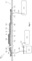
- the system 100 has a composite preform 10 having an upper surface 14 and an opposing lower surface 15.
- the upper and lower surfaces 14, 15 each define a preform major surface.
- the composite preform 10 is a dry preform to be infused with an exothermically curing resin provided in a resin supply 141.
- a heat sink which in the first example is a passive heat sink formed of an endothermic material, is located in proximity to one of the preform major surfaces, and particularly the upper surface 14 in the first example.
- Endothermic materials are materials that absorb energy, typically by a phase change or chemical reaction, when exposed to heat.
- the passive heat sink is in the form of a thermoplastic patch 120.
- the thermoplastic patch 120 extends across only a portion 16 of the upper surface 14.
- the thermoplastic patch 120 thus extends only over a region of the upper surface 14 having a smaller area than the total area of the upper surface 14 and does not extend across the entire upper surface 14.
- the system further comprises a heat source, which may be in the form of an oven 170 (or autoclave), for heating the composite preform 10 to cure the resin, following resin infusion.
- the oven 170 may also be utilized to heat the composite preform 10 and resin supply 141 for resin infusion, as will be discussed below.
- the system is of a single vacuum bag composite layup configuration.
- the system 100 has a tool 110 having an upper tool surface 111, with the lower surface 15 of the composite preform 10 being located on the tool surface 111.
- a vacuum bagging film 130 extends over the composite preform 10 and is sealed relative to the tool surface 111 to define a sealed first cavity 140 between the vacuum bagging film 130 and the tool surface 111.
- the composite preform 10 is located in the first cavity 140.
- the thermoplastic patch 120 is located in proximity to the upper surface 14 of the composite preform 10, particularly being located directly on top of the vacuum bagging film 130.
- the tool 110 may be formed of any of various structural materials, including mild steel, stainless steel, invar or a carbon composite material that will maintain its form at elevated temperatures associated with curing, so as to provide a geometrically stable tool surface 111 though the resin curing process.
- the tool surface 111 may be substantially flat for the production of composite structures having a substantially flat lower surface, such as wing or fuselage skin panels, or otherwise shaped as desired so as to provide a shaped surface of a nonplanar composite structure.
- the composite preform 10 may take any form suitable for resin infusion and as dictated by the geometric and structural requirements of the laminated composite structure to be fabricated.
- the composite preform 10 may comprise a layup of multiple plies of reinforcing material, each formed of woven or braided fibres and/or chopped strand mat.
- the preform plies may be formed of any of various reinforcing fibres, such as carbon, graphite, glass, aromatic polyamide or any other suitable material for fabricating a resin reinforced laminated composite structure.
- the plies may form a dry preform, without any resin, or alternatively the preform may have some pre-existing resin content prior to the resin infusion process.
- the composite preform 10 is located on the tool surface 111 with the lower surface 15 of the preform 10 oriented on the tool surface 111 such that the lower surface of the resulting cured composite structure will match the form of the tool surface 111.
- the composite preform 10 located on the tool surface 111 has a laterally extending downstream edge 11, an opposing laterally extending upstream edge 12 and opposing longitudinally extending side edges 13.
- upstream and downstream sides of the composite preform 10 are identified with reference to the direction of flow of resin, as will be further described.
- the preform 10 may take any desired shape corresponding to the shape of the laminated composite structure to be formed.
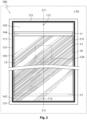
- the composite preform may have a uniform thickness or, alternatively as depicted in the example of Figures 2 and 3 , the composite preform 10 may have a non-uniform thickness as measured between the upper and lower surfaces 14, 15. Particularly, in the arrangement depicted, the portion 16 of the composite preform 10 has a thickness greater than an average thickness of the composite preform 10.
- the thicker portion 16 of the composite preform 10 is in the form of a padup, having an increased thickness as a result of being provided with additional plies of reinforcing material to provide local structural reinforcement. Padups, and other portions of composite preforms having a locally increased thickness, generally have a higher volume of resin per unit of preform surface area once resin infused, given the increased thickness of preform and thus resin.
- Such thicker portions may thus be more susceptible to excessive exothermic heat build-up during exothermic curing of the resin, due to the increased volume of resin.
- Other portions of the composite preform 10 that do not have an increased thickness may also be subject to exothermic heat build up, such as resulting from uneven temperatures within the oven 170, and thus suitable for application of the thermoplastic patch 120.
- the resin supply 141 communicates with the first cavity 140 through one or more resin infusion inlets 112 extending through the tool 110 on the upstream side of the composite preform 10, via one or more resin supply pipes 146.
- the resin supply pipes 146 are typically formed of copper.
- a first vacuum source 151 communicates with the first cavity 140 through one or more vacuum outlets 113 extending through the tool 110 on a downstream side of the composite preform 10, via one or more vacuum outlet pipes 154, which are also typically formed of copper.
- the resin supply 141 and first vacuum source 151 may communicate with the first cavity 151 through the vacuum bagging film 130.
- apertures may be formed in the vacuum bagging film 130 and communicated with the resin supply 141 and first vacuum source 151, sealing around the apertures.
- the resin supply 141 also communicates with a second vacuum source 155 via a second vacuum pipe 157.
- a flow path 142 extends from the resin supply 141, through the first cavity 140, the composite preform 10 and to the first vacuum source 151.
- An upstream portion of the flow path 142 comprises the resin supply pipe(s) 146 and resin infusion inlet 112 extending through the tool 110.
- a mid portion of the flow path 142, defined by the first cavity 140, is formed by the composite preform 10 and various layers of layup materials located beneath the vacuum bagging film 130.
- the layup materials include a permeable peel ply 145 located directly on, and extending over, the entirety of the composite preform 10, beyond each of the edges 11, 12, 13 of the composite preform 10, with a downstream portion 144 of the peel ply 145 extending downstream of the downstream edge 11 of the composite preform 10.
- a layer 147 of permeable flow media is placed over the peel ply 145 and extends beyond the upstream edge of the peel ply 145 to beyond the resin infusion inlet(s) 112.
- the layer 147 of permeable flow media extends to beyond the downstream edge 11 of the composite preform 10 but does not cover the entirety of the downstream portion 144 of the peel ply 145.
- the peel ply 145 serves to prevent the layer 147 of permeable flow media from sticking to the composite preform 10 and also provides a path for infusion of resin into the composite preform 10, both along the upstream edge 12 of the composite preform 10 and through the upper surface 14 of the composite preform 10.
- the peel ply 145 also allows volatiles given off during curing of the resin to be drawn away from the composite preform 10.
- the peel ply 145 also constitutes a permeable flow media, and may suitably be in the form of a PTFE coated fibreglass fabric, such as Release Ease ® 234, available from AirTech International Inc, or any other permeable peel ply material.
- the layer 147 of permeable flow media provides a passage for the resin through the first cavity 140 along the top of the composite preform 10, along with a path for the escape of volatiles from the first cavity 140.
- the layer 147 of permeable flow media may suitably be in the form of a nylon mesh material, such as Plastinet ® 15231 also available from AirTech International Inc, or any other highly permeable media enabling passage of resin therethrough.
- a downstream portion of the flow path 142 comprises a further strip 143 of permeable flow media, the vacuum outlet(s) 113 and vacuum pipe(s) 154.
- the strip 143 of permeable flow media extends across the downstream edge of the downstream portion 144 of the peel ply 145 and extends further downstream across the vacuum outlet(s) 113.
- the strip 143 of permeable flow media is typically formed of the same material as the layer 143 of permeable flow media.
- a gap is located between the layer 147 and strip 143 of permeable flow media.
- the vacuum bagging film 130 extends over the entire layup formed by the composite preform 10, peel ply 145 and layer 147 and strip 143 of permeable flow media. Any of various vacuum bagging film materials may be utilized, including but not limited to Airtech WL7400 or SL800 vacuum bagging films available from Airtech International Inc.
- the vacuum bagging film 130 is sealed relative to the tool surface 111 about the periphery of the vacuum bagging film 130 by way of strips 131 of sealing tape, which may conveniently be in the form of a mastic sealant tape, such as GS-213-3 sealant tape available from AirTech International Inc.
- the vacuum bagging film 130 defines the upper boundary of the resin flow path 142.
- the vacuum bagging film 130 restricts the thickness of the flow path 142 between the tool upper surface 111 and vacuum bagging film 130 to the downstream portion 144 of the peel ply 145, which is typically of a reduced permeability as compared to the layer 147 of permeable flow media. All downstream flow of resin is thus restricted through the downstream portion 144 of the peel ply 145, which defines a permeable resin flow control choke.
- the thermoplastic patch 120 is configured to melt when the thicker portion 16 of the composite preform 10 is subject to excessive exothermic heat build-up during exothermic cure of the resin 141.
- the thermoplastic patch 120 may be selected such that it has a melting temperature exceeding the temperature at which the resin 141 is infused (which may be at an elevated temperature, typically of the order of 100 to 110°C), and equal to or less than the peak exotherm temperature of the resin 141 that would otherwise be experienced during cure without the thermoplastic patch 120 (as may be determined by a trial cure cycle without the thermoplastic patch 120).
- Different epoxy resins may release heat energy as a result of crosslinking during the cure process at different temperatures, depending on the resin selected.
- HexFlow ® RTM6 one epoxy resin commonly used in resin infusion applications, HexFlow ® RTM6, available from Hexcel Corporation, can begin releasing energy from about 140°C during heating to cure temperature.
- HexFlow ® RTM6 may have a peak exotherm temperature of about 190 to 200°C .
- Selecting a thermoplastic material for the thermoplastic patch 120 with a melting temperature less than the peak exotherm temperature, and particularly lying in the range at which the resin releases energy faster than it can be absorbed by the surrounding environment (about 150 0 C to 180 0 C for the example depicted in Figure 1 ) may be appropriate for use with typical epoxy resins.
- Figure 4 provides a graph depicting the melting profile of various thermoplastic materials, as sourced from http://us.mt.com/dam/LabDiv/Campaigns/MPE2013/performance_plastics/download/thermal_an alysis_of_thermoplastics.pdf.
- the graph of Figure 4 depicts the heat flux of each thermoplastic material plotted against temperature through the melting process, with the trough in each graph representing the endothermic melting process.
- the melting phase change comprises an endothermic reaction, allowing the thermoplastic patch 120 to act as a heat sink by absorbing heat.
- thermoplastic patch 120 When the exothermic curing of the resin results in excessive heat energy being released by resin within the portion 16 of the composite preform 10, heat transfers from the upper surface 14 of the composite preform 10 at the portion 16 to the lower surface of the thermoplastic patch 120, due to its proximity.
- the thermoplastic patch 120 should thus be located in sufficient proximity to the upper surface 14 (or lower surface 15) of the composite preform 10 to allow this heat transfer.
- the thermoplastic patch 120 When the thermoplastic patch 120 is heated to a temperature corresponding to the endothermic trough around the melting temperature of the thermoplastic material, the thermoplastic patch 120 absorbs heat energy as it melts, thereby conducting heat away from the portion 16 of the composite preform 10.
- polyoxymethylene which has an endothermic trough and melting temperature at about 170 to 180 0 C
- POM polyoxymethylene
- Other thermoplastic materials with endothermic troughs and melting at lower temperatures may also be suitable, including high density polyoxyethylene (HPPE) which has an endothermic trough and melting temperature within the range of about 130 0 C to 140 0 C, or polypropylene (PP) which has an endothermic trough and melting temperature within the range of about 160 0 C to 170 0 C.
- HPPE high density polyoxyethylene
- PP polypropylene
- thermoplastic materials may alternatively be selected to suit particular applications and resin.
- suitable thermoset resins used for resin infusion may include bismaleimide, benzoxazine, polyimide, cyanate esters and polyamide-imide resins.
- thermoplastic patch 120 may be formed with any size or shape to suit the specific application, and will generally be sized and shaped to generally correspond to the upper surface of the portion 16 of the composite preform 10 that is susceptible to experiencing excessive exothermic heating as a result of local exothermic behaviour of the resin during cure. For any given portion 16, a single thermoplastic patch 120 may be applied or, alternatively, multiple smaller thermoplastic patches 120 may be applied. It is also envisaged that thermoplastic patches 120 may be applied to multiple portions across the upper surface 14 of the composite preform 10 as appropriate where multiple portions may be susceptible to excessive exothermic heating.
- the size and location of portions 16 for application of one or more thermoplastic patches 120 may be determined through simple assessment and identification of regions of the composite preform 10 that have a higher resin content due to locally increased thickness, or through trial and error in processing sample composite preforms without the use of any heat sink, identifying, by way of thermocouple, areas of local overheating. Alternatively, computational modelling may be utilized to identify regions that will likely be susceptible to excessive exothermic heating.
- the resin supply 141 is heated to bring the resin to a suitable resin infusion temperature.
- a suitable resin infusion temperature typically the entire system is heated within the oven 170 that is also used for subsequent curing.
- the temperature for resin infusion will be dependent upon the resin system utilised, and will typically be selected to provide a suitable viscosity enabling the resin to flow through the resin flow path 142.
- a suitable infusion temperature may be in the range of 100 to 110 0 C.
- At least partial vacuum pressure is applied to the downstream end of the first cavity 140, via the first vacuum source 151 and vacuum outlet(s) 113.
- a smaller partial vacuum i.e., a higher absolute pressure
- a pressure differential may be maintained between the first vacuum source 151 and second vacuum source 155 such that the absolute pressure at the vacuum outlet(s) 113 applied by the first vacuum source 151 is lower than the absolute pressure at the resin supply 141.
- a full vacuum (0 mbar / 0 kPa absolute pressure) may be applied by the first vacuum source 151 and a higher pressure / lower vacuum of 500 to 800 mbar absolute pressure (50 to 80 kPa) may be applied to the second vacuum source 155, thereby providing a pressure differential of the same amount driving resin from the resin supply 141 through the resin flow path 142.
- Full vacuum pressure may also be applied to the resin supply 141 by the second vacuum source 155 prior to resin infusion to degas the resin.
- the rate of advance of the resin wave front is inhibited by forcing the resin to pass downstream longitudinally through a permeable resin flow control choke defined by the downstream portion 144 of the peel ply 145 once it passes the downstream edge 11 of the composite preform 10 and the downstream edge of the layer 147 of permeable flow media.
- the resin infused composite preform 10 may then be cured by gradually elevating the temperature of the oven 170 to a temperature suitable for curing of the resin.
- a temperature suitable for curing of the resin For typical epoxy resins, curing temperatures of the order of 180 0 C to 200 0 C will be typical.
- Full vacuum is typically maintained on the first vacuum source 151 during the curing process, to ensure the resin infused composite preform 10 remains consolidated and to assist in curing of the resin.
- thermoplastic patch 120 will melt, thereby conducting heat away from the portion 16 of the composite preform 10, with the heat being absorbed through the endothermic reaction of the melting process.
- the oven 170 may be heated to curing temperature more rapidly, and potentially to a higher curing temperature for quicker cure, than otherwise available without the use of the thermoplastic patch 120, with a decreased risk of overheating the portion 16 of the composite preform 10. More rapid process cycle times, whilst maintaining reliable cure, may thus be obtained.
- Vacuum bagging films typically exhibit some air permeability, particularly at elevated temperatures associated with resin infusion and/or resin cure. Accordingly, one potential deficiency of the single vacuum bag configuration of the resin infusion system 100 of the first example is that, with vacuum applied during the curing process, air may permeate through the vacuum bagging film 130 and into the composite preform 10, potentially resulting in porosity and resin starvation within the cured composite laminate.
- a double bag resin infusion system is thus envisaged in an effort to minimise or avoid such air permeation, by providing a second vacuum bagging film covering the first vacuum bagging film and applying vacuum pressure to the second vacuum bagging film during both the resin infusion and curing stages of operation.
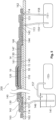
- Figure 5 depicts a schematic cross-sectional view (corresponding to Figure 3 ) of such a double-bag configuration of the system 100 of the first example, fabricating a system 200 according to a second example.
- the system 200 of the second example is substantially identical to the system 100 of the first example, with the addition of a second vacuum bagging film 160 and associated breather layer 161. Accordingly, features of the system 200 of the second example that are identical to features of the system 100 of the first example are provided with identical reference numerals and will not be further discussed.
- the composite preform 10 and associated consumable layers are first assembled in the same manner as described above in relation to the system 100 of the first example.
- the thermoplastic patch 120 is also located on the first vacuum bagging film 130 in the manner described above in relation to the first example.
- a breather layer 161, typically being a highly permeable fabric formed of fibreglass or the like is then located over, and fully covering, the first vacuum bagging film 130 and the thermoplastic patch 120.
- a suitable breather layer is a breather cloth formed of a high film non-woven polyester material, such as Airweave ® N10, available from Airtech International Inc.
- the breather layer 161 extends over a vacuum groove 114 that extends around the perimeter of the tool surface 111 and is connected to the first vacuum source 151 (or a separate third vacuum source) by way of a third vacuum pipe 158.
- the second vacuum bagging film 160 is then located to cover the entire breather layer 161 and is sealed relative to the tool surface 111 by way of further strips 162 of sealing tape, forming a sealed second cavity 163 between the first and second vacuum bagging films 130, 160.
- the composite preform 10 is resin infused and subsequently cured using the same process as described above in relation to the system 100 of the first example, with at least a partial vacuum being applied to the second cavity 163 between the first and second vacuum bagging films 130, 160 by the first vacuum source 151 (or separate third vacuum source) throughout resin infusion and curing.
- the second vacuum bagging film 160 and associated vacuum applied to the second cavity 163 protects against any minor leaks associated with the first vacuum bag 130, with the vacuum applied evacuating any air permeating through the second vacuum bagging film 160 toward the composite preform 10 through the breather layer 161, rather than allowing it to permeate through to the composite preform 10.
- Figure 6 depicts a schematic cross-sectional view of another double-bag configuration, forming a system 300 according to a third example, not in accordance with the present claims .
- the system 300 of the third example is substantially identical to the system 200 of the second example, apart from the location and arrangement of the thermoplastic patch 120. Accordingly, features of the system 200 of the second example that are identical to features of the systems 100, 200 of the first and second examples are provided with identical reference numerals and will not be further discussed.
- thermoplastic patch 120 is located beneath the first vacuum bagging film 130, on top of the layer 147 of permeable flow media.
- the thermoplastic patch 120 may conveniently be housed within a pocket 121 of non-porous release film, such as Airtech A7250, available from Airtech International Inc.
- the thermoplastic patch 120 may alternatively be otherwise isolated from the composite preform 10 to avoid contact with melted thermoplastic material.
- the system 300 of the third example is operated in the same manner as the system 200 of the second example to form a composite structure.
- thermoplastic patch 120 may be modified to locate the thermoplastic patch 120 beneath the vacuum bagging film 130, preferably within a pocket of release film or similar, in a similar manner.
- the thermoplastic patch 120 could alternatively be located on the exterior of either the single-bag system 100 of the first example, on the vacuum bagging film 130, or on the exterior of the double-bag system 200, 300 of either of the second or third examples, on the second vacuum bagging film 160. It is, however, preferred to located the thermoplastic patch 120 in greater proximity to the surface of the composite preform 10 to enhance heat transfer between the composite preform 10 and the thermoplastic patch 120.
- thermoplastic patch 120 may be located in proximity to the lower surface 15 of the composite preform 10 rather than upper surface 14.
- the thermoplastic patch 120 could be located on the lower surface of the tool 110, particularly when a relatively thin tool is utilized.
- the thermoplastic patch 120 could be located between the tool surface 11 and the lower surface 15 of the composite preform 10, typically within a pocket of non-porous release film. Such a location may, however make an undesirable imprint on the lower surface 15 of the composite preform 10.
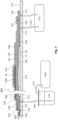
- Figure 7 depicts a schematic cross-sectional view of a further double-bag configuration that is identical to the configuration of the system 200 of the second example, apart from the configuration of heat sink. Accordingly, features of the system 400 of the fourth example that are identical to features of the systems of the first through third examples are provided with identical reference numerals and will not be further discussed.
- an active heat sink is utilised.
- the active heat sink is in the form of a thermoelectric cooling device 420.
- Thermoelectric cooling devices otherwise commonly referred to as Peltier devices or Peltier heat pumps, generate a heat flux between two adjacent plates of differing materials upon application of a voltage cross the plates.
- thermoelectric cooling devices with maximum operating temperatures exceeding the exotherm peak temperature of the resin being utilized would be particularly suitable.
- Such a thermoelectric cooling device may be utilised with the cooling side of the thermoelectric device located in proximity to the upper surface 14 of the composite preform, thereby conducting heat away from the thickened portion 16 of the composite preform 10 during curing.
- thermoelectric cooling device 420 is located on the first vacuum bag 130, within the second cavity 163 between the first and second vacuum bags 130, 160.
- a pair of wires 422, that are used to apply the voltage to the thermoelectric cooling device 420, may pass along the second cavity 163 and through to the exterior of the system 400 through the sealing tape 162 sealing the second vacuum bag 160 to the tool surface 111.
- the wires 422 could extend through an aperture formed in the second vacuum bag 160, with the aperture appropriately sealed.
- the system 400 of the fourth example is operated in the same manner as the system 200 of the second example to form a composite structure except that, rather than conducting heat away from the portion 16 of the composite preform 10 passively with the thermoplastic patch 120, heat is conducted away actively by operating the thermoelectric cooling device 120 during the cure cycle.
- thermoelectric cooling device 420 could alternatively be located on the exterior of the system 400, on the second vacuum bagging film 160, although it is preferred to located the thermoelectric cooling device 420 in greater proximity to the localised region 16 of the composite preform 10. It is also envisaged that the thermoelectric cooling device 420 could be located below the first vacuum bagging film 130, within a pocket of release film, in a similar manner to the arrangement of the thermoplastic patch 120 in the system 300 of the third example, or in proximity to the lower surface 15 of the composite preform 15.
- thermoelectric cooling device Rather than utilizing a thermoelectric cooling device, other forms of active heat sink are also envisaged.
- One such alternative may be a radiator and coolant arrangement, in which a series of tubes are arranged in proximity to the upper surface 14 of the composite preform 10 at the thickened portion 16 with coolant pumped through the tubes to conduct heat away from the portion 16.
- Figure 8 depicts a schematic cross-sectional view of a system 500 for fabricating a composite structure according to a fifth example.
- the system 500 involves fabricating a composite structure from prepreg composite material, rather than resin infusing a dry composite preform as part of the process, as is the case with the first through fourth examples.
- Features of the system 500 of the fifth example that are identical or equivalent to features of the first through fourth examples described above are provided with like reference numerals.
- the composite preform 20 comprises a pluarality of plies of prepreg composite material. With resin being pre-impregnated in the prepreg composite material there is no need for a resin infusion process, as is the case with the first through fourth examples.
- the composite preform 20 has an upper surface 24 and an opposing lower surface 25.
- the upper and lower surfaces 24, 25 each define a preform major surface.
- a heat sink which may be a passive heat sink formed of an endothermic material, such as a thermoplastic patch 120 as described above, or an active heat sink such as a thermoelectric cooling device, is located in proximity to one of the preform major surfaces, and particularly the upper surface 24 in the depicted example.
- the thermoplastic patch 120 extends across only a portion 26 of the composite preform 20.
- the portion 26 may be a portion of the composite preform 20 that is susceptible to excessive exothermic heating during resin cure, such as a thicker portion of the composite preform 20 forming a padup.
- the system 500 further comprises a heat source, which may again be in the form of an oven (not depicted) for heating the composite preform 20 to cure the pre-impregnated resin within the composite preform 20.
- the composite preform 20 is located on the upper tool surface 111 of a tool 110 and a vacuum bagging film 130 is again sealed relative to the tool surface 111 to define a sealed first cavity 140 between the vacuum bagging film 130 and the tool surface 111, with the composite preform 20 located in the first cavity 140.
- Various layers of layup materials are located beneath the vacuum bagging film 130. Specifically, a permeable peel ply 145 is located directly on, and extends over, the entirety of the composite preform 20.
- a bleeder layer 546 is located on, and extends over, the permeable peel ply 145.
- the bleeder layer 546 acts to absorb any excess resin bleeding from the composite preform 20 when compacted under atmospheric pressure, and also provides a path for the escape of volatiles during the curing procedure.
- a release film 547 is located on and extends over the bleeder layer 546 so as to retain excess resin within the bleeder layer 546 and prevent the same from sticking to the breather layer 161 that is located on, and extends over, the release film 547.
- the breather layer 161 extends beyond the composite preform 20, peel ply 145, bleeder layer 546 and release film 547 to beyond a vacuum outlet 113 which communicates with a first vacuum source 151 by way of a vacuum pipe 154.
- thermoplastic patch 120 is located on the release film 547, which is generally non-porous.
- the release film 547 will thus prevent the thermoplastic patch 120, when melted, from mixing with and sticking to the composite preform 20.
- thermoplastic patch 120 may be located beneath the release film 547, located within a pocket of release film, in a similar manner to the third example, with the release film pocket acting to prevent the thermoplastic patch 120 from mixing with or sticking to the composite preform 20 upon melting.
- thermoplastic patch 120 might be located on top of the vacuum bagging film 130, or in proximity to the lower surface 25 of the composite preform 20.
- At least partial vacuum pressure typically full vacuum pressure (0 mBar/0 kPa absolute pressure) is applied to the first cavity 140 by the first vacuum source 151, thereby allowing atmospheric pressure (or greater via the aid of an autoclave) acting on the exterior of the vacuum bagging film 130 to act on the composite preform 20 and compact the same.
- the composite preform 20 may then be cured by gradually elevating the temperature of the oven or autoclave to a temperature suitable for curing of the resin. For typical epoxy resins, curing temperatures of the order of 180°C to 200°C will again be typical.
- a general method of resin infusing the composite preform as discussed above is depicted in general terms in the flow diagram of Figure 9 .
- a composite preform having an upper surface and an opposing lower surface is provided. The upper and lower surfaces each defining a preform major surface.
- a block 402 a heat sink is located in proximity to one of the preform major surfaces so as to extend across only a portion of the composite preform.
- a resin is exothermically cured in the composite preform to form the composite structure.
- heat is conducted away from the portion of the composite preform into the heat sink.
Landscapes
- Engineering & Computer Science (AREA)
- Mechanical Engineering (AREA)
- Chemical & Material Sciences (AREA)
- Composite Materials (AREA)
- Physics & Mathematics (AREA)
- Thermal Sciences (AREA)
- General Engineering & Computer Science (AREA)
- Casting Or Compression Moulding Of Plastics Or The Like (AREA)
- Moulding By Coating Moulds (AREA)
Claims (15)
- Verfahren zur Herstellung einer Verbundstoffstruktur, wobei das Verfahren aufweist:Bereitstellen eines Verbundstoff-Vorformlings (10), der eine obere Oberfläche (14) und eine gegenüberliegende untere Oberfläche (15) hat, wobei die obere und untere Oberfläche (14, 15) jeweils eine Vorformling-Hauptfläche definieren;Anordnen einer Wärmesenke (120) nahe an einer der Vorformling-Hauptflächen, so dass sie nur einen Teil (16) des Verbundstoff-Vorformlings (10) überlappt;Aushärten eines Harzes in dem Verbundstoff-Vorformling (10), um die Verbundstoffstruktur zu bilden, wobei das Harz exotherm aushärtet; undwährend Aushärtung des Harzes, Leiten von Wärme weg von dem Teil (16) des Verbundstoff-Vorformlings (10) in die Wärmesenke (120),wobei das Verfahren ferner aufweist:Anordnen der unteren Oberfläche (15) des Verbundstoff-Vorformlings (10) auf einer oberen Werkzeugoberfläche (111) eines Werkzeugs (100);Legen einer ersten Vakuumbeutelfolie (130) über den Verbundstoff-Vorformling (10) und Versiegeln der ersten Vakuumbeutelfolie (130) relativ zu der oberen Werkzeugoberfläche (111), um zwischen der ersten Vakuumbeutelfolie (130) und der oberen Werkzeugoberfläche (111) einen versiegelten ersten Hohlraum (140) zu definieren, wobei der Verbundstoff-Vorformling (10) in dem ersten Hohlraum (140) angeordnet ist; undAnlegen mindestens eines Partialvakuumdrucks an den ersten Hohlraum (140) während Aushärtung des Harzes;und wobei die Wärmesenke (120) oberhalb der ersten Vakuumbeutelfolie (130) nahe an der oberen Oberfläche (14) des Verbundstoff-Vorformlings (10) angeordnet ist.
- Verfahren nach Anspruch 1, wobei Anordnen der Wärmesenke aufweist: Anordnen einer aus einem endothermen Material gebildeten passiven Wärmesenke (120).
- Verfahren nach Anspruch 2, wobei die passive Wärmesenke (120) ein Stück eines thermoplastischen Materials (120) aufweist, das eine Schmelztemperatur hat, die gleich oder niedriger als eine exotherme Höchsttemperatur des Harzes ist.
- Verfahren nach Anspruch 1, wobei Anordnen der Wärmesenke aufweist: Anordnen einer aktiven Wärmesenke (420).
- Verfahren nach einem der Ansprüche 1 bis 4, wobei Bereitstellen des Verbundstoff-Vorformlings (10) aufweist: Bereitstellen eines Verbundstoff-Vorformlings (10), der eine ungleichmäßige Dicke, gemessen zwischen der oberen und unteren Oberfläche (14, 15), hat, wobei der Teil (16) des Verbundstoff-Vorformlings (10) eine Dicke hat, die größer als eine durchschnittliche Dicke des Verbundstoff-Vorformlings (10) ist.
- Verfahren nach einem der Ansprüche 1 bis 5, ferner aufweisend Gießen des Harzes in den Verbundstoff-Vorformling (10) vor Aushärtung des Harzes.
- Verfahren nach einem der Ansprüche 1 bis 6, wobei Bereitstellen des Verbundstoff-Vorformlings (20) aufweist: Bereitstellen eines Verbundstoff-Vorformlings (20), der mehrere Schichten eines Prepreg-Verbundstoffmaterials aufweist, wobei das Harz in dem Prepreg-Verbundstoffmaterial vorimprägniert ist.
- System zur Herstellung einer Verbundstoffstruktur, wobei das System aufweist:einen Verbundstoff-Vorformling (10), der eine obere Oberfläche (14) und eine gegenüberliegende untere Oberfläche (15) hat, wobei die obere und untere Oberfläche (14, 15) jeweils eine Vorformling-Hauptfläche definieren;ein exotherm aushärtendes Harz, das in den Verbundstoff-Vorformling (10) zu gießen ist oder das in dem Verbundstoff-Vorformling (20) vorimprägniert ist;eine Wärmesenke (120), die nahe an einer der Vorformling-Hauptflächen (14, 15) angeordnet ist, so dass sie nur einen Teil (16) der Vorformling-Hauptfläche (14, 15) überlappt, wobei die Wärmesenke (120) verwendet wird, um während Aushärtung des Harzes Wärme weg von dem Teil (16) in die Wärmesenke (120) zu leiten; undeine Wärmequelle (170) zum Erhitzen des Verbundstoff-Vorformlings (10), um das Harz auszuhärten;wobei das System ferner aufweist:ein Werkzeug, das eine obere Werkzeugoberfläche (111) hat, wobei die untere Oberfläche (15) des Verbundstoff-Vorformlings (10) auf der oberen Werkzeugoberfläche (111) angeordnet ist;eine erste Vakuumbeutelfolie (130), die sich über den Verbundstoff-Vorformling (10) erstreckt und relativ zu der oberen Werkzeugoberfläche (111) versiegelt ist, um zwischen der ersten Vakuumbeutelfolie (130) und der oberen Werkzeugoberfläche (111) einen ersten Hohlraum (140) zu definieren, wobei der Verbundstoff-Vorformling (10) in dem ersten Hohlraum (140) angeordnet ist; undeine Vakuumquelle (151), die mit dem ersten Hohlraum (140) in Verbindung steht;wobei die Wärmesenke (120) oberhalb der ersten Vakuumbeutelfolie (130) nahe an der oberen Oberfläche (14) des Verbundstoff-Vorformlings (10) angeordnet ist, undwobei der Verbundstoff-Vorformling (10) eine ungleichmäßige Dicke, gemessen zwischen der oberen und unteren Oberfläche (14, 15), hat, wobei der Teil (16) des Verbundstoff-Vorformlings (10) eine Dicke hat, die größer als eine durchschnittliche Dicke des Verbundstoff-Vorformlings (10) ist.
- System nach Anspruch 8, wobei der Teil (16) des Verbundstoff-Vorformlings (1) in Form einer Aufpolsterung ist, die mit zusätzlichen Schichten eines verstärkenden Materials versehen ist, um lokale strukturelle Verstärkung bereitzustellen.
- System nach Anspruch 8 oder 9, wobei die Wärmesenke eine aus einem endothermen Material gebildete passive Wärmesenke (120) ist.
- System nach Anspruch 10, wobei die passive Wärmesenke (120) ein Stück (120) eines thermoplastischen Materials aufweist, das Stück (120) eine Schmelztemperatur hat, die gleich oder niedriger als eine exotherme Höchsttemperatur des Harzes ist.
- System nach Anspruch 8 oder 9, wobei die Wärmesenke eine aktive Wärmesenke (420) ist, die eine thermoelektrische Kühlvorrichtung aufweist, deren maximale Arbeitstemperaturen eine exotherme Höchsttemperatur des Harzes überschreiten.
- System nach einem der Ansprüche 8 bis 12, ferner aufweisend:eine zweite Vakuumbeutelfolie (160), die sich über die erste Vakuumbeutelfolie (130) und die Wärmesenke (120) erstreckt und relativ zu der Werkzeugoberfläche (111) versiegelt ist, um zwischen der ersten und der zweiten Vakuumbeutelfolie (130, 160) einen zweiten Hohlraum (163) zu definieren;wobei die Vakuumquelle (151) in Verbindung mit dem zweiten Hohlraum (163) steht und die Wärmesenke (120) in dem zweiten Hohlraum (163) angeordnet ist.
- System nach einem der Ansprüche 8 bis 13, wobei das Harz in den Verbundstoff-Vorformling (10) zu gießen ist.
- System nach einem der Ansprüche 8 bis 14, wobei der Verbundstoff-Vorformling (20) mehrere Schichten eines Prepreg-Verbundstoffmaterials, die das Harz enthalten, aufweist.
Applications Claiming Priority (1)
| Application Number | Priority Date | Filing Date | Title |
|---|---|---|---|
| AU2016203504A AU2016203504B2 (en) | 2016-05-27 | 2016-05-27 | A method and system for fabricating a composite structure |
Publications (2)
| Publication Number | Publication Date |
|---|---|
| EP3248766A1 EP3248766A1 (de) | 2017-11-29 |
| EP3248766B1 true EP3248766B1 (de) | 2024-10-23 |
Family
ID=58265864
Family Applications (1)
| Application Number | Title | Priority Date | Filing Date |
|---|---|---|---|
| EP17160025.7A Active EP3248766B1 (de) | 2016-05-27 | 2017-03-09 | Verfahren und vorrichtung zur herstellung einer verbundstoffstruktur |
Country Status (4)
| Country | Link |
|---|---|
| US (1) | US11065828B2 (de) |
| EP (1) | EP3248766B1 (de) |
| AU (1) | AU2016203504B2 (de) |
| SG (1) | SG10201704211TA (de) |
Families Citing this family (5)
| Publication number | Priority date | Publication date | Assignee | Title |
|---|---|---|---|---|
| CN109955499B (zh) * | 2019-04-04 | 2021-02-09 | 北京卫星制造厂有限公司 | 一种返回式飞船大底防热层成型工装 |
| US11220072B2 (en) * | 2020-01-02 | 2022-01-11 | The Boeing Company | Molding system and methods for forming structures |
| US20210244249A1 (en) | 2020-02-10 | 2021-08-12 | Matician, Inc. | Configuration of a cleaning head for an autonomous vacuum |
| US12321669B2 (en) * | 2022-12-07 | 2025-06-03 | The Boeing Company | Thermal management for composite tooling |
| US12226932B2 (en) | 2022-12-07 | 2025-02-18 | The Boeing Company | Tool comprising eutectic material, method of making the tool and method of using the tool |
Family Cites Families (8)
| Publication number | Priority date | Publication date | Assignee | Title |
|---|---|---|---|---|
| US3840626A (en) * | 1969-05-21 | 1974-10-08 | Volkswagenwerk Ag | Method for producing a hollow plastic object |
| US5240542A (en) * | 1990-09-06 | 1993-08-31 | The Board Of Trustees Of The Leland Stanford Junior University | Joining of composite materials by induction heating |
| AU3789801A (en) * | 1999-12-07 | 2001-06-18 | Boeing Company, The | Double bag vacuum infusion process and system for low cost, advanced composite fabrication |
| US6627018B1 (en) | 2000-10-17 | 2003-09-30 | Advance Usa, Llc | System and method of forming composite structures |
| JP2004130723A (ja) * | 2002-10-11 | 2004-04-30 | Mitsubishi Heavy Ind Ltd | 繊維強化樹脂構造体の製造方法及び、その製造装置 |
| US8834668B2 (en) * | 2008-11-19 | 2014-09-16 | The Boeing Company | Staged cocuring of composite structures |
| EP2952335B1 (de) | 2014-06-02 | 2017-11-29 | Siemens Aktiengesellschaft | Herstellungsverfahren und Vorrichtung zur Herstellung von Verbundwerkstoffteilen mit einer Vorrichtung zum Absorbieren von Wärme |
| US10636952B2 (en) * | 2015-01-09 | 2020-04-28 | Asahi Fr R&D Co., Ltd. | Flexible peltier device and temperature regulation apparatus |
-
2016
- 2016-05-27 AU AU2016203504A patent/AU2016203504B2/en active Active
-
2017
- 2017-03-09 EP EP17160025.7A patent/EP3248766B1/de active Active
- 2017-05-10 US US15/592,129 patent/US11065828B2/en active Active
- 2017-05-23 SG SG10201704211TA patent/SG10201704211TA/en unknown
Also Published As
| Publication number | Publication date |
|---|---|
| EP3248766A1 (de) | 2017-11-29 |
| US20170341317A1 (en) | 2017-11-30 |
| AU2016203504A1 (en) | 2017-12-14 |
| US11065828B2 (en) | 2021-07-20 |
| AU2016203504B2 (en) | 2022-04-14 |
| SG10201704211TA (en) | 2017-12-28 |
Similar Documents
| Publication | Publication Date | Title |
|---|---|---|
| EP3248766B1 (de) | Verfahren und vorrichtung zur herstellung einer verbundstoffstruktur | |
| CN105936131B (zh) | 用于结合复合材料结构的共固化工艺 | |
| US4560428A (en) | System and method for producing cured composites | |
| EP1948425B1 (de) | Harzmasseninfusionsvorrichtung und -verfahren | |
| US20160159057A1 (en) | Forming of staged thermoset composite materials | |
| CN106738523B (zh) | 长纤维及连续纤维增强热塑性复合材料的电阻加热快速成型方法 | |
| US9994008B2 (en) | Method and system for compacting composite part layup utilizing a single release film layer | |
| US20140119813A1 (en) | Exposing Fibers in Composite Laminates | |
| US20160332392A1 (en) | Method of forming composite structures | |
| WO2013011306A1 (en) | Method for laminating items and items obtained by the method | |
| EP2842711A1 (de) | Vorrichtung und Verfahren zur Herstellung einer Flugzeugkomponente aus Verbundmaterial | |
| EP3853014A1 (de) | Verfahren und system zum schmelzen von thermoplastischen verbundstrukturen | |
| WO2014070379A1 (en) | Over-molded vacuum barrier and inner mold line bag carrier with soluble details in trapped closed mold tooling | |
| EP4043188B1 (de) | Verfahren und vorrichtungen zum widerstandsschweissen | |
| EP1595688B1 (de) | Geformter Schichtstoff und Verfahren zu dessen Herstellung | |
| CN112277341A (zh) | 用于湿复合材料铺设的半径填料 | |
| US20140080376A1 (en) | Engineered high fiber volume polymer matrix composites | |
| EP3616890B1 (de) | Vorformformverfahren und verbundformverfahren | |
| EP3266595B1 (de) | Verfahren und system zur harzinfusion einer verbundstoffvorform | |
| CA2900635C (en) | Multifunctional mandrel end cap and method | |
| KR102799195B1 (ko) | 복합 재료 및 이의 제조 방법 | |
| JP6582429B2 (ja) | サンドイッチ成形体およびその成形方法ならびに成形装置 | |
| US12427729B2 (en) | Method of joining molded or three-dimensional printed parts to thermoplastic composite structures | |
| EP3812139A1 (de) | Herstellung von verbundteilen | |
| US20250387987A1 (en) | Method of joining molded or three-dimensional printed parts to thermoplastic composite structures |
Legal Events
| Date | Code | Title | Description |
|---|---|---|---|
| PUAI | Public reference made under article 153(3) epc to a published international application that has entered the european phase |
Free format text: ORIGINAL CODE: 0009012 |
|
| STAA | Information on the status of an ep patent application or granted ep patent |
Free format text: STATUS: REQUEST FOR EXAMINATION WAS MADE |
|
| 17P | Request for examination filed |
Effective date: 20170309 |
|
| AK | Designated contracting states |
Kind code of ref document: A1 Designated state(s): AL AT BE BG CH CY CZ DE DK EE ES FI FR GB GR HR HU IE IS IT LI LT LU LV MC MK MT NL NO PL PT RO RS SE SI SK SM TR |
|
| AX | Request for extension of the european patent |
Extension state: BA ME |
|
| RBV | Designated contracting states (corrected) |
Designated state(s): AL AT BE BG CH CY CZ DE DK EE ES FI FR GB GR HR HU IE IS IT LI LT LU LV MC MK MT NL NO PL PT RO RS SE SI SK SM TR |
|
| STAA | Information on the status of an ep patent application or granted ep patent |
Free format text: STATUS: EXAMINATION IS IN PROGRESS |
|
| 17Q | First examination report despatched |
Effective date: 20210506 |
|
| RAP3 | Party data changed (applicant data changed or rights of an application transferred) |
Owner name: THE BOEING COMPANY |
|
| GRAP | Despatch of communication of intention to grant a patent |
Free format text: ORIGINAL CODE: EPIDOSNIGR1 |
|
| STAA | Information on the status of an ep patent application or granted ep patent |
Free format text: STATUS: GRANT OF PATENT IS INTENDED |
|
| INTG | Intention to grant announced |
Effective date: 20240404 |
|
| RIN1 | Information on inventor provided before grant (corrected) |
Inventor name: ROBERTS, RICHARD WILLIAM |
|
| GRAJ | Information related to disapproval of communication of intention to grant by the applicant or resumption of examination proceedings by the epo deleted |
Free format text: ORIGINAL CODE: EPIDOSDIGR1 |
|
| STAA | Information on the status of an ep patent application or granted ep patent |
Free format text: STATUS: EXAMINATION IS IN PROGRESS |
|
| GRAP | Despatch of communication of intention to grant a patent |
Free format text: ORIGINAL CODE: EPIDOSNIGR1 |
|
| STAA | Information on the status of an ep patent application or granted ep patent |
Free format text: STATUS: GRANT OF PATENT IS INTENDED |
|
| INTC | Intention to grant announced (deleted) | ||
| INTG | Intention to grant announced |
Effective date: 20240528 |
|
| P01 | Opt-out of the competence of the unified patent court (upc) registered |
Free format text: CASE NUMBER: APP_42219/2024 Effective date: 20240717 |
|
| GRAS | Grant fee paid |
Free format text: ORIGINAL CODE: EPIDOSNIGR3 |
|
| GRAA | (expected) grant |
Free format text: ORIGINAL CODE: 0009210 |
|
| STAA | Information on the status of an ep patent application or granted ep patent |
Free format text: STATUS: THE PATENT HAS BEEN GRANTED |
|
| AK | Designated contracting states |
Kind code of ref document: B1 Designated state(s): AL AT BE BG CH CY CZ DE DK EE ES FI FR GB GR HR HU IE IS IT LI LT LU LV MC MK MT NL NO PL PT RO RS SE SI SK SM TR |
|
| REG | Reference to a national code |
Ref country code: GB Ref legal event code: FG4D |
|
| REG | Reference to a national code |
Ref country code: CH Ref legal event code: EP |
|
| REG | Reference to a national code |
Ref country code: DE Ref legal event code: R096 Ref document number: 602017085619 Country of ref document: DE |
|
| REG | Reference to a national code |
Ref country code: IE Ref legal event code: FG4D |
|
| REG | Reference to a national code |
Ref country code: LT Ref legal event code: MG9D |
|
| REG | Reference to a national code |
Ref country code: NL Ref legal event code: MP Effective date: 20241023 |
|
| REG | Reference to a national code |
Ref country code: AT Ref legal event code: MK05 Ref document number: 1734511 Country of ref document: AT Kind code of ref document: T Effective date: 20241023 |
|
| PG25 | Lapsed in a contracting state [announced via postgrant information from national office to epo] |
Ref country code: NL Free format text: LAPSE BECAUSE OF FAILURE TO SUBMIT A TRANSLATION OF THE DESCRIPTION OR TO PAY THE FEE WITHIN THE PRESCRIBED TIME-LIMIT Effective date: 20241023 |
|
| PG25 | Lapsed in a contracting state [announced via postgrant information from national office to epo] |
Ref country code: NL Free format text: LAPSE BECAUSE OF FAILURE TO SUBMIT A TRANSLATION OF THE DESCRIPTION OR TO PAY THE FEE WITHIN THE PRESCRIBED TIME-LIMIT Effective date: 20241023 |
|
| PG25 | Lapsed in a contracting state [announced via postgrant information from national office to epo] |
Ref country code: IS Free format text: LAPSE BECAUSE OF FAILURE TO SUBMIT A TRANSLATION OF THE DESCRIPTION OR TO PAY THE FEE WITHIN THE PRESCRIBED TIME-LIMIT Effective date: 20250223 Ref country code: HR Free format text: LAPSE BECAUSE OF FAILURE TO SUBMIT A TRANSLATION OF THE DESCRIPTION OR TO PAY THE FEE WITHIN THE PRESCRIBED TIME-LIMIT Effective date: 20241023 Ref country code: PT Free format text: LAPSE BECAUSE OF FAILURE TO SUBMIT A TRANSLATION OF THE DESCRIPTION OR TO PAY THE FEE WITHIN THE PRESCRIBED TIME-LIMIT Effective date: 20250224 |
|
| PG25 | Lapsed in a contracting state [announced via postgrant information from national office to epo] |
Ref country code: FI Free format text: LAPSE BECAUSE OF FAILURE TO SUBMIT A TRANSLATION OF THE DESCRIPTION OR TO PAY THE FEE WITHIN THE PRESCRIBED TIME-LIMIT Effective date: 20241023 |
|
| PG25 | Lapsed in a contracting state [announced via postgrant information from national office to epo] |
Ref country code: BG Free format text: LAPSE BECAUSE OF FAILURE TO SUBMIT A TRANSLATION OF THE DESCRIPTION OR TO PAY THE FEE WITHIN THE PRESCRIBED TIME-LIMIT Effective date: 20241023 |
|
| PG25 | Lapsed in a contracting state [announced via postgrant information from national office to epo] |
Ref country code: ES Free format text: LAPSE BECAUSE OF FAILURE TO SUBMIT A TRANSLATION OF THE DESCRIPTION OR TO PAY THE FEE WITHIN THE PRESCRIBED TIME-LIMIT Effective date: 20241023 |
|
| PG25 | Lapsed in a contracting state [announced via postgrant information from national office to epo] |
Ref country code: NO Free format text: LAPSE BECAUSE OF FAILURE TO SUBMIT A TRANSLATION OF THE DESCRIPTION OR TO PAY THE FEE WITHIN THE PRESCRIBED TIME-LIMIT Effective date: 20250123 |
|
| PG25 | Lapsed in a contracting state [announced via postgrant information from national office to epo] |
Ref country code: LV Free format text: LAPSE BECAUSE OF FAILURE TO SUBMIT A TRANSLATION OF THE DESCRIPTION OR TO PAY THE FEE WITHIN THE PRESCRIBED TIME-LIMIT Effective date: 20241023 Ref country code: AT Free format text: LAPSE BECAUSE OF FAILURE TO SUBMIT A TRANSLATION OF THE DESCRIPTION OR TO PAY THE FEE WITHIN THE PRESCRIBED TIME-LIMIT Effective date: 20241023 Ref country code: GR Free format text: LAPSE BECAUSE OF FAILURE TO SUBMIT A TRANSLATION OF THE DESCRIPTION OR TO PAY THE FEE WITHIN THE PRESCRIBED TIME-LIMIT Effective date: 20250124 |
|
| PG25 | Lapsed in a contracting state [announced via postgrant information from national office to epo] |
Ref country code: PL Free format text: LAPSE BECAUSE OF FAILURE TO SUBMIT A TRANSLATION OF THE DESCRIPTION OR TO PAY THE FEE WITHIN THE PRESCRIBED TIME-LIMIT Effective date: 20241023 |
|
| PG25 | Lapsed in a contracting state [announced via postgrant information from national office to epo] |
Ref country code: RS Free format text: LAPSE BECAUSE OF FAILURE TO SUBMIT A TRANSLATION OF THE DESCRIPTION OR TO PAY THE FEE WITHIN THE PRESCRIBED TIME-LIMIT Effective date: 20250123 |
|
| PG25 | Lapsed in a contracting state [announced via postgrant information from national office to epo] |
Ref country code: SM Free format text: LAPSE BECAUSE OF FAILURE TO SUBMIT A TRANSLATION OF THE DESCRIPTION OR TO PAY THE FEE WITHIN THE PRESCRIBED TIME-LIMIT Effective date: 20241023 |
|
| PG25 | Lapsed in a contracting state [announced via postgrant information from national office to epo] |
Ref country code: DK Free format text: LAPSE BECAUSE OF FAILURE TO SUBMIT A TRANSLATION OF THE DESCRIPTION OR TO PAY THE FEE WITHIN THE PRESCRIBED TIME-LIMIT Effective date: 20241023 |
|
| PG25 | Lapsed in a contracting state [announced via postgrant information from national office to epo] |
Ref country code: EE Free format text: LAPSE BECAUSE OF FAILURE TO SUBMIT A TRANSLATION OF THE DESCRIPTION OR TO PAY THE FEE WITHIN THE PRESCRIBED TIME-LIMIT Effective date: 20241023 |
|
| PG25 | Lapsed in a contracting state [announced via postgrant information from national office to epo] |
Ref country code: RO Free format text: LAPSE BECAUSE OF FAILURE TO SUBMIT A TRANSLATION OF THE DESCRIPTION OR TO PAY THE FEE WITHIN THE PRESCRIBED TIME-LIMIT Effective date: 20241023 |
|
| REG | Reference to a national code |
Ref country code: DE Ref legal event code: R097 Ref document number: 602017085619 Country of ref document: DE |
|
| PG25 | Lapsed in a contracting state [announced via postgrant information from national office to epo] |
Ref country code: SK Free format text: LAPSE BECAUSE OF FAILURE TO SUBMIT A TRANSLATION OF THE DESCRIPTION OR TO PAY THE FEE WITHIN THE PRESCRIBED TIME-LIMIT Effective date: 20241023 |
|
| PG25 | Lapsed in a contracting state [announced via postgrant information from national office to epo] |
Ref country code: CZ Free format text: LAPSE BECAUSE OF FAILURE TO SUBMIT A TRANSLATION OF THE DESCRIPTION OR TO PAY THE FEE WITHIN THE PRESCRIBED TIME-LIMIT Effective date: 20241023 |
|
| PG25 | Lapsed in a contracting state [announced via postgrant information from national office to epo] |
Ref country code: IT Free format text: LAPSE BECAUSE OF FAILURE TO SUBMIT A TRANSLATION OF THE DESCRIPTION OR TO PAY THE FEE WITHIN THE PRESCRIBED TIME-LIMIT Effective date: 20241023 |
|
| PLBE | No opposition filed within time limit |
Free format text: ORIGINAL CODE: 0009261 |
|
| STAA | Information on the status of an ep patent application or granted ep patent |
Free format text: STATUS: NO OPPOSITION FILED WITHIN TIME LIMIT |
|
| PG25 | Lapsed in a contracting state [announced via postgrant information from national office to epo] |
Ref country code: SE Free format text: LAPSE BECAUSE OF FAILURE TO SUBMIT A TRANSLATION OF THE DESCRIPTION OR TO PAY THE FEE WITHIN THE PRESCRIBED TIME-LIMIT Effective date: 20241023 |
|
| 26N | No opposition filed |
Effective date: 20250724 |
|
| PG25 | Lapsed in a contracting state [announced via postgrant information from national office to epo] |
Ref country code: MC Free format text: LAPSE BECAUSE OF FAILURE TO SUBMIT A TRANSLATION OF THE DESCRIPTION OR TO PAY THE FEE WITHIN THE PRESCRIBED TIME-LIMIT Effective date: 20241023 |
|
| REG | Reference to a national code |
Ref country code: CH Ref legal event code: H13 Free format text: ST27 STATUS EVENT CODE: U-0-0-H10-H13 (AS PROVIDED BY THE NATIONAL OFFICE) Effective date: 20251023 |
|
| PG25 | Lapsed in a contracting state [announced via postgrant information from national office to epo] |
Ref country code: LU Free format text: LAPSE BECAUSE OF NON-PAYMENT OF DUE FEES Effective date: 20250309 |
|
| REG | Reference to a national code |
Ref country code: BE Ref legal event code: MM Effective date: 20250331 |
|
| PG25 | Lapsed in a contracting state [announced via postgrant information from national office to epo] |
Ref country code: BE Free format text: LAPSE BECAUSE OF NON-PAYMENT OF DUE FEES Effective date: 20250331 |
|
| PG25 | Lapsed in a contracting state [announced via postgrant information from national office to epo] |
Ref country code: CH Free format text: LAPSE BECAUSE OF NON-PAYMENT OF DUE FEES Effective date: 20250331 |
|
| PG25 | Lapsed in a contracting state [announced via postgrant information from national office to epo] |
Ref country code: IE Free format text: LAPSE BECAUSE OF NON-PAYMENT OF DUE FEES Effective date: 20250309 |
|
| PGFP | Annual fee paid to national office [announced via postgrant information from national office to epo] |
Ref country code: GB Payment date: 20260327 Year of fee payment: 10 |
|
| PGFP | Annual fee paid to national office [announced via postgrant information from national office to epo] |
Ref country code: DE Payment date: 20260327 Year of fee payment: 10 |
|
| PGFP | Annual fee paid to national office [announced via postgrant information from national office to epo] |
Ref country code: FR Payment date: 20260325 Year of fee payment: 10 |