EP3248719B1 - Verfahren und vorrichtung zum additiven herstellen zumindest eines bauteilbereichs eines bauteils - Google Patents
Verfahren und vorrichtung zum additiven herstellen zumindest eines bauteilbereichs eines bauteils Download PDFInfo
- Publication number
- EP3248719B1 EP3248719B1 EP17172381.0A EP17172381A EP3248719B1 EP 3248719 B1 EP3248719 B1 EP 3248719B1 EP 17172381 A EP17172381 A EP 17172381A EP 3248719 B1 EP3248719 B1 EP 3248719B1
- Authority
- EP
- European Patent Office
- Prior art keywords
- component
- layer
- energy beam
- contour
- powder layer
- Prior art date
- Legal status (The legal status is an assumption and is not a legal conclusion. Google has not performed a legal analysis and makes no representation as to the accuracy of the status listed.)
- Not-in-force
Links
Images

Classifications
-
- B—PERFORMING OPERATIONS; TRANSPORTING
- B22—CASTING; POWDER METALLURGY
- B22F—WORKING METALLIC POWDER; MANUFACTURE OF ARTICLES FROM METALLIC POWDER; MAKING METALLIC POWDER; APPARATUS OR DEVICES SPECIALLY ADAPTED FOR METALLIC POWDER
- B22F5/00—Manufacture of workpieces or articles from metallic powder characterised by the special shape of the product
- B22F5/009—Manufacture of workpieces or articles from metallic powder characterised by the special shape of the product of turbine components other than turbine blades
-
- B—PERFORMING OPERATIONS; TRANSPORTING
- B22—CASTING; POWDER METALLURGY
- B22F—WORKING METALLIC POWDER; MANUFACTURE OF ARTICLES FROM METALLIC POWDER; MAKING METALLIC POWDER; APPARATUS OR DEVICES SPECIALLY ADAPTED FOR METALLIC POWDER
- B22F10/00—Additive manufacturing of workpieces or articles from metallic powder
- B22F10/20—Direct sintering or melting
- B22F10/28—Powder bed fusion, e.g. selective laser melting [SLM] or electron beam melting [EBM]
-
- B—PERFORMING OPERATIONS; TRANSPORTING
- B22—CASTING; POWDER METALLURGY
- B22F—WORKING METALLIC POWDER; MANUFACTURE OF ARTICLES FROM METALLIC POWDER; MAKING METALLIC POWDER; APPARATUS OR DEVICES SPECIALLY ADAPTED FOR METALLIC POWDER
- B22F10/00—Additive manufacturing of workpieces or articles from metallic powder
- B22F10/30—Process control
- B22F10/32—Process control of the atmosphere, e.g. composition or pressure in a building chamber
-
- B—PERFORMING OPERATIONS; TRANSPORTING
- B22—CASTING; POWDER METALLURGY
- B22F—WORKING METALLIC POWDER; MANUFACTURE OF ARTICLES FROM METALLIC POWDER; MAKING METALLIC POWDER; APPARATUS OR DEVICES SPECIALLY ADAPTED FOR METALLIC POWDER
- B22F12/00—Apparatus or devices specially adapted for additive manufacturing; Auxiliary means for additive manufacturing; Combinations of additive manufacturing apparatus or devices with other processing apparatus or devices
- B22F12/40—Radiation means
- B22F12/44—Radiation means characterised by the configuration of the radiation means
- B22F12/45—Two or more
-
- B—PERFORMING OPERATIONS; TRANSPORTING
- B23—MACHINE TOOLS; METAL-WORKING NOT OTHERWISE PROVIDED FOR
- B23K—SOLDERING OR UNSOLDERING; WELDING; CLADDING OR PLATING BY SOLDERING OR WELDING; CUTTING BY APPLYING HEAT LOCALLY, e.g. FLAME CUTTING; WORKING BY LASER BEAM
- B23K15/00—Electron-beam welding or cutting
- B23K15/0046—Welding
- B23K15/0086—Welding welding for purposes other than joining, e.g. build-up welding
-
- B—PERFORMING OPERATIONS; TRANSPORTING
- B23—MACHINE TOOLS; METAL-WORKING NOT OTHERWISE PROVIDED FOR
- B23K—SOLDERING OR UNSOLDERING; WELDING; CLADDING OR PLATING BY SOLDERING OR WELDING; CUTTING BY APPLYING HEAT LOCALLY, e.g. FLAME CUTTING; WORKING BY LASER BEAM
- B23K15/00—Electron-beam welding or cutting
- B23K15/10—Non-vacuum electron beam-welding or cutting
-
- B—PERFORMING OPERATIONS; TRANSPORTING
- B23—MACHINE TOOLS; METAL-WORKING NOT OTHERWISE PROVIDED FOR
- B23K—SOLDERING OR UNSOLDERING; WELDING; CLADDING OR PLATING BY SOLDERING OR WELDING; CUTTING BY APPLYING HEAT LOCALLY, e.g. FLAME CUTTING; WORKING BY LASER BEAM
- B23K26/00—Working by laser beam, e.g. welding, cutting or boring
- B23K26/12—Working by laser beam, e.g. welding, cutting or boring in a special environment or atmosphere, e.g. in an enclosure
- B23K26/123—Working by laser beam, e.g. welding, cutting or boring in a special environment or atmosphere, e.g. in an enclosure in an atmosphere of particular gases
-
- B—PERFORMING OPERATIONS; TRANSPORTING
- B23—MACHINE TOOLS; METAL-WORKING NOT OTHERWISE PROVIDED FOR
- B23K—SOLDERING OR UNSOLDERING; WELDING; CLADDING OR PLATING BY SOLDERING OR WELDING; CUTTING BY APPLYING HEAT LOCALLY, e.g. FLAME CUTTING; WORKING BY LASER BEAM
- B23K26/00—Working by laser beam, e.g. welding, cutting or boring
- B23K26/34—Laser welding for purposes other than joining
- B23K26/342—Build-up welding
-
- B—PERFORMING OPERATIONS; TRANSPORTING
- B33—ADDITIVE MANUFACTURING TECHNOLOGY
- B33Y—ADDITIVE MANUFACTURING, i.e. MANUFACTURING OF THREE-DIMENSIONAL [3D] OBJECTS BY ADDITIVE DEPOSITION, ADDITIVE AGGLOMERATION OR ADDITIVE LAYERING, e.g. BY 3D PRINTING, STEREOLITHOGRAPHY OR SELECTIVE LASER SINTERING
- B33Y10/00—Processes of additive manufacturing
-
- B—PERFORMING OPERATIONS; TRANSPORTING
- B33—ADDITIVE MANUFACTURING TECHNOLOGY
- B33Y—ADDITIVE MANUFACTURING, i.e. MANUFACTURING OF THREE-DIMENSIONAL [3D] OBJECTS BY ADDITIVE DEPOSITION, ADDITIVE AGGLOMERATION OR ADDITIVE LAYERING, e.g. BY 3D PRINTING, STEREOLITHOGRAPHY OR SELECTIVE LASER SINTERING
- B33Y30/00—Apparatus for additive manufacturing; Details thereof or accessories therefor
-
- B—PERFORMING OPERATIONS; TRANSPORTING
- B33—ADDITIVE MANUFACTURING TECHNOLOGY
- B33Y—ADDITIVE MANUFACTURING, i.e. MANUFACTURING OF THREE-DIMENSIONAL [3D] OBJECTS BY ADDITIVE DEPOSITION, ADDITIVE AGGLOMERATION OR ADDITIVE LAYERING, e.g. BY 3D PRINTING, STEREOLITHOGRAPHY OR SELECTIVE LASER SINTERING
- B33Y80/00—Products made by additive manufacturing
-
- B—PERFORMING OPERATIONS; TRANSPORTING
- B22—CASTING; POWDER METALLURGY
- B22F—WORKING METALLIC POWDER; MANUFACTURE OF ARTICLES FROM METALLIC POWDER; MAKING METALLIC POWDER; APPARATUS OR DEVICES SPECIALLY ADAPTED FOR METALLIC POWDER
- B22F10/00—Additive manufacturing of workpieces or articles from metallic powder
- B22F10/60—Treatment of workpieces or articles after build-up
- B22F10/62—Treatment of workpieces or articles after build-up by chemical means
-
- B—PERFORMING OPERATIONS; TRANSPORTING
- B22—CASTING; POWDER METALLURGY
- B22F—WORKING METALLIC POWDER; MANUFACTURE OF ARTICLES FROM METALLIC POWDER; MAKING METALLIC POWDER; APPARATUS OR DEVICES SPECIALLY ADAPTED FOR METALLIC POWDER
- B22F10/00—Additive manufacturing of workpieces or articles from metallic powder
- B22F10/60—Treatment of workpieces or articles after build-up
- B22F10/66—Treatment of workpieces or articles after build-up by mechanical means
-
- B—PERFORMING OPERATIONS; TRANSPORTING
- B22—CASTING; POWDER METALLURGY
- B22F—WORKING METALLIC POWDER; MANUFACTURE OF ARTICLES FROM METALLIC POWDER; MAKING METALLIC POWDER; APPARATUS OR DEVICES SPECIALLY ADAPTED FOR METALLIC POWDER
- B22F12/00—Apparatus or devices specially adapted for additive manufacturing; Auxiliary means for additive manufacturing; Combinations of additive manufacturing apparatus or devices with other processing apparatus or devices
- B22F12/40—Radiation means
- B22F12/41—Radiation means characterised by the type, e.g. laser or electron beam
- B22F12/42—Light-emitting diodes [LED]
-
- B—PERFORMING OPERATIONS; TRANSPORTING
- B23—MACHINE TOOLS; METAL-WORKING NOT OTHERWISE PROVIDED FOR
- B23K—SOLDERING OR UNSOLDERING; WELDING; CLADDING OR PLATING BY SOLDERING OR WELDING; CUTTING BY APPLYING HEAT LOCALLY, e.g. FLAME CUTTING; WORKING BY LASER BEAM
- B23K2103/00—Materials to be soldered, welded or cut
- B23K2103/02—Iron or ferrous alloys
-
- Y—GENERAL TAGGING OF NEW TECHNOLOGICAL DEVELOPMENTS; GENERAL TAGGING OF CROSS-SECTIONAL TECHNOLOGIES SPANNING OVER SEVERAL SECTIONS OF THE IPC; TECHNICAL SUBJECTS COVERED BY FORMER USPC CROSS-REFERENCE ART COLLECTIONS [XRACs] AND DIGESTS
- Y02—TECHNOLOGIES OR APPLICATIONS FOR MITIGATION OR ADAPTATION AGAINST CLIMATE CHANGE
- Y02P—CLIMATE CHANGE MITIGATION TECHNOLOGIES IN THE PRODUCTION OR PROCESSING OF GOODS
- Y02P10/00—Technologies related to metal processing
- Y02P10/25—Process efficiency
Definitions
- the invention relates to a method and a device for the additive production of at least one component region of a component.
- additive or additive manufacturing methods are known in which the component, which may be, for example, a component of a turbomachine or an aircraft engine, is built up in layers.
- Predominantly metallic components can be produced, for example, by laser or electron beam melting methods.
- at least one powdered component material is initially applied in layers in the region of a buildup and joining zone, in order to form a powder layer.
- the component material is locally solidified by supplying energy to the component material in the region of the assembly and joining zone by means of at least one high-energy beam, whereby the component material melts and forms a component layer.
- the high-energy beam is controlled in dependence on a layer information of the component layer to be produced in each case.
- the layer information is usually generated from a 3D CAD body of the component and subdivided into individual component layers. After solidification of the molten component material, the component platform is lowered in layers by a predefined layer thickness. Thereafter, the said steps are repeated until the final completion of the desired component area or the entire component.
- the component region or the component can in principle be produced on a component platform or on an already produced part of the component or component region.
- a method of making a fully dense three-dimensional metal article is disclosed.
- the inner portion of the article is formed by selective laser sintering in a cross section of a powder layer.
- the laser is formed around the inner portion of the article in this layer to form a gas impermeable skin. The process is repeated until the article is completed.
- the article surrounded by the skin is then hot isostatically pressed to densify the article.
- a generative manufacturing process is known in which, during the formation of a molten bath, back-up heating is used to heat the material in a region adjacent to the molten bath to a temperature below the melting point of the powder used, the region being an upstream region of the bath and a region downstream of the bath.
- the material in the upstream region is heated to reduce a cooling rate of the material below its natural cooling rate.
- the material in the downstream region is heated to reduce the rate of heating of the material below its natural heating rate to the melting point.
- the material in a portion of a region adjacent to the molten bath is heated to a temperature between one-third and one-half the melting point.
- the US 2014/348692 A1 discloses an apparatus and method for producing a three-dimensional object by successively layering selected zones of a powder layer, wherein the solidified zones correspond to successive sections of the three-dimensional object.
- an outer boundary of the powder layer is solidified by means of a laser beam along a preset path which corresponds to the contour of the outer boundary and follows the contour of the cross section of the object.
- the central inner part of the powder layer is selectively melted by moving the electron beam of the second energy source relative to the object by means of an electron beam originating from a second energy source.
- the US 2014/334924 A1 discloses a method of producing a device generatively wherein material is selectively joined layer by layer to a layer or substrate disposed thereunder.
- a laser acts before, during and / or after the connection to the material.
- Object of the present invention is to provide a generic method and a generic device, which allows the additive production of component areas or complete components with improved surface quality.
- a first aspect of the invention relates to a method for the additive production of at least one component region of a component, in particular a component of a turbomachine, in which at least the steps a) applying at least one layer of powdered component material to a component platform in the region of a buildup and joining zone, b) local solidification of the powder layer by selective exposure by means of at least one high-energy beam in the region of the assembly and joining zone to form a component layer, c) lowering the component platform by a predefined layer thickness and d) repeating steps a) to c) until completion of the component region or component.
- step b1) at least once by means of at least one high-energy beam such that the solidified powder layer is locally heated but not melted, and in a temporally subsequent step b2) by means of at least one high-energy beam is exposed so that the solidified Powder layer is locally melted in the region of the contour section.
- step b1) is carried out at least twice before step b2) is carried out, wherein a direction of movement of the at least one high-energy beam along the contour section is reversed after at least one embodiment of step b1).
- the energy input through the at least one high energy beam is thus controlled so that the resulting temperature of the component layer in the contour line as close as possible to the melting temperature of the relevant component material, ie, for example, a maximum of 20 K, 10 K, 5 K, 2 K or less below the melting temperature lies, but it comes to no renewed melting.
- This sudden heating of the contour line leads to a pressure surge, which pushes powder particles which are in direct contact with the surface.
- this contour segment is remelted, for example with conventional parameters, that is to say, for example, with parameters which have already been used in a similar or similar manner in the volume exposure in step b), that is, heated above the melting temperature.
- conventional parameters that is to say, for example, with parameters which have already been used in a similar or similar manner in the volume exposure in step b)
- the two steps b1) and b2) can in principle only be carried out for a contour section which is particularly relevant with regard to the surface quality, for a plurality of locally spaced and / or contiguous contour sections or along the entire contour line of the component layer.
- step b1) is performed at least twice before step b2) is performed.
- step b2) is performed.
- the respective contour portion or the entire contour of the component layer is twice or more with the at least one High-energy beam down to locally heat the component material in this area, but without melting it.
- step b2) a direction of movement of the at least one high-energy beam along the contour section is reversed after at least one execution of step b1).
- the at least one high-energy beam is moved in the first implementation of step b1) in a first direction along the respective contour section or along the entire contour of the component layer and in another of step b1) in one of the first Direction opposite direction along the respective contour portion or along the entire contour of the component layer is moved. In this way, it can be ensured in a particularly reliable manner that the surface remains free of powder particles at least until the remelting in step b2).
- the at least one high-energy beam in step b1) and step b2) is operated with a power deviating by a maximum of ⁇ 10% or reduced by up to 90%.
- the power of the at least one high-energy beam during step b1) and step b2) can be kept at least substantially constant. This simplifies the control or regulation of the at least one high-energy beam and its energy input into the contour region of the component layer, since the contour region or the contour after step b1) is already heated, so that in step b2) a melting can be achieved with the same energy input , Alternatively or additionally, it can be provided that the at least one high-energy beam in step b1) and step b2) is moved at different speeds along the contour section.
- the at least one high-energy beam is moved in step b2) at a speed which is lower than the speed in step b1).
- the at least one high-energy beam may be moved at a speed of 10 m / s in step b1), while it is moved in step b2) only at a speed of 5 m / s, 2 m / s, 1 m / s or less ,
- a protective gas atmosphere can in principle be any suitable and under the process parameters not reacting with the component material gas or gas mixture, such as argon and / or nitrogen can be used.
- argon and / or nitrogen can be used.
- a protective gas atmosphere in addition to a protection of the component layer from oxidation and a particularly high surface quality can be achieved because the inert gas by local heating in step b1) locally abruptly expands and thus leads to a pressure surge, which is particularly close to the surface powder reliably pushes away from the surface.
- steps b1) and b2) are carried out for at least two different contour sections and preferably for all contour sections of a single component layer and / or for at least two component layers and preferably for each component layer. This makes it possible to qualitatively improve either only particularly relevant surface areas of the component or the entire surface of the component, whereby the method can be carried out particularly economically.
- steps b1) and b2) are carried out simultaneously at different contour sections by means of at least one split high-energy beam and / or by means of a plurality of high-energy beams.
- This allows a simultaneous surface processing of two or more contour sections, whereby the processing and production time of the component layer and thus of the component area or component can advantageously be reduced.
- an electron beam and / or a laser beam is used as the high-energy beam.
- component regions or components can be produced whose mechanical properties at least substantially correspond to those of the component material.
- For generating the laser beam for example CO 2 laser, Nd: YAG laser, Yb fiber laser, diode laser or the like may be provided. It can also be provided that two or more electron or laser beams are used in order to reduce the processing time and / or to be able to produce particularly large-area component layers.
- a second aspect of the invention relates to a device for the additive production of at least one component region of a component, in particular of a component of a turbomachine, wherein the device comprises at least one coater for applying at least one powder layer from a powdered component material to a building and joining zone of a lowerable component platform and at least one radiation source for generating at least one high-energy beam, by means of which the powder layer in the region of the assembly and joining zone is locally solidified to a component layer comprises.
- the device comprising a control device which is designed to control the radiation source in such a way that at least one contour section of at least one component layer is exposed in one step at least twice by means of at least one high-energy beam in that the solidified powder layer is locally heated but not melted, the control means being arranged to reverse a direction of movement of the at least one high energy beam along the contour section after at least one of step b1), and wherein the control means is adapted to form the solidified powder layer be exposed in a temporally subsequent step by means of at least one high-energy beam in such a way that the solidified powder layer is locally melted in the region of the contour section ,
- the term "trained to” is understood to mean not only a control device which has the fundamental property for carrying out said steps, but which is specifically designed and set up to actually carry out said steps.
- the device can comprise a controllable and / or controllable radiation source or a plurality of controllable and / or controllable radiation sources in order to generate the respectively required high-energy beams.
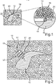
- Fig. 1 shows a schematic plan view of an additively produced component layer 10 of a turbine component for a thermal gas turbine together with an enlargement of a contour section 12 during the exposure with a high-energy beam 14.
- a powder layer 16 made of a powdered component material is first applied in layers in a manner known per se to a component platform (not shown) in the region of an assembly and joining zone 18. Subsequently, the powder layer 16 is locally solidified by selectively exposing it by means of at least one high-energy beam 14, for example a laser beam in the region of the assembly and joining zone 18 to form the device layer 10.
- the component platform is lowered by a predefined layer thickness, after which the said steps are repeated until the completion of a component area or a complete component.
- a predefined layer thickness it can be seen in the magnification that when exposing the powder layer 16 according to the arrows shown along the contour line 20 particles 16 adhere to the surface of the component layer 10 and are melted down with or adhere to the surface. This leads to very rough surfaces, which in turn negatively influence the strength of the component layer 10 and have to be reworked laboriously, which is sometimes not possible, in particular for interior surface areas.
- Fig. 2 shows a schematic plan view of a device layer 10 produced according to the invention.
- Fig. 2 is described below in synopsis with FIG. 3 to FIG. 5 which are each schematic enlargements of the in Fig. 2 shown contour portion 12 during the in Fig. 2 show with the arrows b1 and b2 marked process steps.
- the contour section 12 which must have a high surface quality, is exposed in a first step b1 by means of at least one high-energy beam 14 in such a way that the solidified powder layer 16 is locally heated but not yet remelted.
- the high-energy beam 14 is moved in accordance with the first arrow b1 quickly and with low path energy along the contour line 20 in the contour section 12.
- a fundamentally optional protective gas eg argon
- a construction space of a device (not shown) used to carry out the method is filled.
- a fundamentally optional protective gas eg argon
- the contour line 20 is exposed in the opposite direction in a second step b1 again with the high energy beam 14, without causing the component layer 10 to melt.
- Fig. 4 shows. It can be seen that the immediately adjacent powder particles 16 are pushed away from the surface or the contour line 20 due to the resulting pressure surge due to the protective gas.
- a subsequent step b2 in which the direction of the high-energy beam is again reversed so that the exposure takes place in the same direction as in the first step b1, the Contour line 20 exposed to the high energy beam 14 such that the solidified powder layer is melted in the region of the contour portion 12 locally with conventional parameters.
- Fig. 5 shown.
- no more particles are 16 to the molten bath, whereby caking reliably prevented and a high surface quality is ensured.
- the described steps can be performed successively along further contour sections 12 or along the entire contour line 20.
- steps b1 (2x) and b2 the high-energy beam 14 is operated at a constant power, for example at 300 W, but at different speeds.
- the high-energy beam 14 is respectively moved at about 10 m / s, while it is moved slower in step b2, for example at 1 m / s.
- the energy input and thus the heating or melting are controlled.
- a plurality of high energy beams 14 may be used to perform steps b1 and b2. It can also be provided that a plurality of high-energy beams 14 are used to process a plurality of contour sections 12 at the same time.
- the aforementioned steps b1 and b2 can also be carried out, if required, at a plurality of component layers 10 or at each component layer 10.
Landscapes
- Engineering & Computer Science (AREA)
- Manufacturing & Machinery (AREA)
- Materials Engineering (AREA)
- Chemical & Material Sciences (AREA)
- Mechanical Engineering (AREA)
- Physics & Mathematics (AREA)
- Plasma & Fusion (AREA)
- Toxicology (AREA)
- General Health & Medical Sciences (AREA)
- Health & Medical Sciences (AREA)
- Optics & Photonics (AREA)
- Automation & Control Theory (AREA)
- Powder Metallurgy (AREA)
- Laser Beam Processing (AREA)
Priority Applications (1)
| Application Number | Priority Date | Filing Date | Title |
|---|---|---|---|
| PL17172381T PL3248719T3 (pl) | 2016-05-25 | 2017-05-23 | Sposób i urządzenie do addytywnej produkcji co najmniej jednego obszaru elementu |
Applications Claiming Priority (1)
| Application Number | Priority Date | Filing Date | Title |
|---|---|---|---|
| DE102016209084.4A DE102016209084A1 (de) | 2016-05-25 | 2016-05-25 | Verfahren und Vorrichtung zum additiven Herstellen zumindest eines Bauteilbereichs eines Bauteils |
Publications (2)
| Publication Number | Publication Date |
|---|---|
| EP3248719A1 EP3248719A1 (de) | 2017-11-29 |
| EP3248719B1 true EP3248719B1 (de) | 2019-05-01 |
Family
ID=59009505
Family Applications (1)
| Application Number | Title | Priority Date | Filing Date |
|---|---|---|---|
| EP17172381.0A Not-in-force EP3248719B1 (de) | 2016-05-25 | 2017-05-23 | Verfahren und vorrichtung zum additiven herstellen zumindest eines bauteilbereichs eines bauteils |
Country Status (4)
| Country | Link |
|---|---|
| US (1) | US20170341175A1 (pl) |
| EP (1) | EP3248719B1 (pl) |
| DE (1) | DE102016209084A1 (pl) |
| PL (1) | PL3248719T3 (pl) |
Cited By (1)
| Publication number | Priority date | Publication date | Assignee | Title |
|---|---|---|---|---|
| US12324932B2 (en) | 2022-03-03 | 2025-06-10 | TRUMPF Additive Manufacturing Italia S.r.l. | Method and planning device for planning a locally selective irradiation of a working area, computer program, method and manufacturing device for additively manufacturing an object from a powder material |
Families Citing this family (5)
| Publication number | Priority date | Publication date | Assignee | Title |
|---|---|---|---|---|
| US11426818B2 (en) | 2018-08-10 | 2022-08-30 | The Research Foundation for the State University | Additive manufacturing processes and additively manufactured products |
| WO2020058722A1 (en) * | 2018-09-20 | 2020-03-26 | Camadd Ltd | A powder bed: additive manufacturing |
| JP7272989B2 (ja) * | 2020-03-31 | 2023-05-12 | 三菱重工業株式会社 | ガスタービン燃焼器、バーナ部品の製造方法 |
| FR3118429B1 (fr) * | 2020-12-30 | 2023-11-24 | Commissariat Energie Atomique | Procédé de fabrication pour pièce fonctionnelle métallique délimitant un média de filtration poreux, utilisant une méthode de fabrication additive, et pièce fonctionnelle obtenue |
| DE102022104752A1 (de) * | 2022-02-28 | 2023-08-31 | Trumpf Laser- Und Systemtechnik Gmbh | Additives Fertigungsverfahren unter Reduzierung der Oberflächenrauheit eines in dem Fertigungsverfahren hergestellten Formkörpers |
Family Cites Families (7)
| Publication number | Priority date | Publication date | Assignee | Title |
|---|---|---|---|---|
| US5640667A (en) * | 1995-11-27 | 1997-06-17 | Board Of Regents, The University Of Texas System | Laser-directed fabrication of full-density metal articles using hot isostatic processing |
| DE102010048335A1 (de) * | 2010-10-13 | 2012-04-19 | Mtu Aero Engines Gmbh | Verfahren und Vorrichtung zur generativen Herstellung |
| DE102011086889A1 (de) * | 2011-11-22 | 2013-05-23 | Mtu Aero Engines Gmbh | Generatives Herstellen eines Bauteils |
| FR2984779B1 (fr) * | 2011-12-23 | 2015-06-19 | Michelin Soc Tech | Procede et appareil pour realiser des objets tridimensionnels |
| FR2998819B1 (fr) * | 2012-11-30 | 2020-01-31 | Association Pour La Recherche Et Le Developpement De Methodes Et Processus Industriels "Armines" | Procede de fusion de poudre avec chauffage de la zone adjacente au bain |
| EP3181336A1 (de) * | 2015-12-17 | 2017-06-21 | Lilas GmbH | 3d-druck-vorrichtung für die herstellung eines räumlich ausgedehnten produkts |
| ITUA20162544A1 (it) * | 2016-04-13 | 2017-10-13 | 3D New Tech S R L | Apparecchiatura per additive manufacturing ad elevata produttivita’ e procedimento di additive manufacturing |
-
2016
- 2016-05-25 DE DE102016209084.4A patent/DE102016209084A1/de not_active Withdrawn
-
2017
- 2017-05-22 US US15/600,934 patent/US20170341175A1/en not_active Abandoned
- 2017-05-23 PL PL17172381T patent/PL3248719T3/pl unknown
- 2017-05-23 EP EP17172381.0A patent/EP3248719B1/de not_active Not-in-force
Non-Patent Citations (1)
| Title |
|---|
| None * |
Cited By (1)
| Publication number | Priority date | Publication date | Assignee | Title |
|---|---|---|---|---|
| US12324932B2 (en) | 2022-03-03 | 2025-06-10 | TRUMPF Additive Manufacturing Italia S.r.l. | Method and planning device for planning a locally selective irradiation of a working area, computer program, method and manufacturing device for additively manufacturing an object from a powder material |
Also Published As
| Publication number | Publication date |
|---|---|
| PL3248719T3 (pl) | 2020-06-15 |
| DE102016209084A1 (de) | 2017-11-30 |
| EP3248719A1 (de) | 2017-11-29 |
| US20170341175A1 (en) | 2017-11-30 |
Similar Documents
| Publication | Publication Date | Title |
|---|---|---|
| EP3183083B2 (de) | Verfahren zum herstellen eines dreidimensionalen objekts | |
| EP3010672B1 (de) | Vorrichtung und verfahren zur generativen herstellung zumindest eines bauteilbereichs eines bauteils | |
| EP2794152B1 (de) | Verfahren zur fertigung eines kompakten bauteils sowie mit dem verfahren herstellbares bauteil | |
| EP3621758B1 (de) | Verfahren für ein additiv herzustellendes bauteil mit vorbestimmter oberflächenstruktur | |
| EP3022008B1 (de) | Verfahren zur herstellung eines bauteils sowie optische bestrahlungsvorrichtung | |
| EP3235580B1 (de) | Verfahren und vorrichtung zum herstellen zumindest eines bauteilbereichs eines bauteils | |
| EP3248719A1 (de) | Verfahren und vorrichtung zum additiven herstellen zumindest eines bauteilbereichs eines bauteils | |
| EP3542927A1 (de) | Verfahren zum selektiven bestrahlen einer materialschicht, verfahren zum bereitstellen eines datensatzes, vorrichtung und computerprogrammprodukt | |
| DE102016205432A1 (de) | Verfahren und Vorrichtung zum additiven Herstellen zumindest eines Bauteilbereichs eines Bauteils | |
| EP2913124A2 (de) | Erzeugung von Druckeigenspannungen bei generativer Fertigung | |
| DE102016209618A1 (de) | Verfahren und Vorrichtung zum additiven Herstellen zumindest eines Bauteilbereichs eines Bauteils | |
| DE102014108081A1 (de) | Vorrichtung und Verfahren zur generativen Herstellung zumindest eines Bauteilbereichs eines Bauteils | |
| EP3455014B1 (de) | Vorrichtung mit schleuse für die additive herstellung | |
| EP3338918A1 (de) | Schichtbauvorrichtung und schichtbauverfahren zum additiven herstellen zumindest eines bauteilbereichs eines bauteils | |
| WO2020211887A1 (de) | Schichtbauverfahren und schichtbauvorrichtung zum additiven herstellen zumindest einer wand eines bauteils sowie computerprogrammprodukt und speichermedium | |
| EP3381593B1 (de) | Verfahren zum strahlbasierten selektiven schmelzen oder sintern | |
| DE102016211068A1 (de) | Verfahren zum Herstellen mindestens eines Bauteils | |
| WO2022167408A1 (de) | Bestrahlungsstrategie für die additive herstellung mit gepulster bestrahlung | |
| EP3175941B1 (de) | Verfahren und vorrichtung zum additiven herstellen zumindest eines bauteilbereichs eines bauteils | |
| AT523693B1 (de) | Verfahren zur Herstellung eines dreidimensionalen Bauteils | |
| EP4225523A1 (de) | Bestrahlungsstrategie in der additiven herstellung mit gepulster bestrahlung | |
| DE19721595B4 (de) | Material zur direkten Herstellung metallischer Funktionsmuster | |
| DE102015201552B4 (de) | Herstellvorrichtung für die Herstellung von dreidimensionalen Objekten mittels Lasersintern | |
| DE102016207893A1 (de) | Bauplattform für die additive Herstellung und Verfahren | |
| DE102018204191A1 (de) | Vorrichtung zum additiven Herstellen zumindest eines Bauteilbereichs eines Bauteils und Schichtbauverfahren |
Legal Events
| Date | Code | Title | Description |
|---|---|---|---|
| PUAI | Public reference made under article 153(3) epc to a published international application that has entered the european phase |
Free format text: ORIGINAL CODE: 0009012 |
|
| STAA | Information on the status of an ep patent application or granted ep patent |
Free format text: STATUS: THE APPLICATION HAS BEEN PUBLISHED |
|
| AK | Designated contracting states |
Kind code of ref document: A1 Designated state(s): AL AT BE BG CH CY CZ DE DK EE ES FI FR GB GR HR HU IE IS IT LI LT LU LV MC MK MT NL NO PL PT RO RS SE SI SK SM TR |
|
| AX | Request for extension of the european patent |
Extension state: BA ME |
|
| STAA | Information on the status of an ep patent application or granted ep patent |
Free format text: STATUS: REQUEST FOR EXAMINATION WAS MADE |
|
| 17P | Request for examination filed |
Effective date: 20180515 |
|
| RBV | Designated contracting states (corrected) |
Designated state(s): AL AT BE BG CH CY CZ DE DK EE ES FI FR GB GR HR HU IE IS IT LI LT LU LV MC MK MT NL NO PL PT RO RS SE SI SK SM TR |
|
| GRAP | Despatch of communication of intention to grant a patent |
Free format text: ORIGINAL CODE: EPIDOSNIGR1 |
|
| STAA | Information on the status of an ep patent application or granted ep patent |
Free format text: STATUS: GRANT OF PATENT IS INTENDED |
|
| INTG | Intention to grant announced |
Effective date: 20190123 |
|
| GRAS | Grant fee paid |
Free format text: ORIGINAL CODE: EPIDOSNIGR3 |
|
| GRAA | (expected) grant |
Free format text: ORIGINAL CODE: 0009210 |
|
| STAA | Information on the status of an ep patent application or granted ep patent |
Free format text: STATUS: THE PATENT HAS BEEN GRANTED |
|
| AK | Designated contracting states |
Kind code of ref document: B1 Designated state(s): AL AT BE BG CH CY CZ DE DK EE ES FI FR GB GR HR HU IE IS IT LI LT LU LV MC MK MT NL NO PL PT RO RS SE SI SK SM TR |
|
| REG | Reference to a national code |
Ref country code: GB Ref legal event code: FG4D Free format text: NOT ENGLISH |
|
| REG | Reference to a national code |
Ref country code: CH Ref legal event code: EP Ref country code: AT Ref legal event code: REF Ref document number: 1126254 Country of ref document: AT Kind code of ref document: T Effective date: 20190515 |
|
| REG | Reference to a national code |
Ref country code: DE Ref legal event code: R096 Ref document number: 502017001205 Country of ref document: DE Ref country code: IE Ref legal event code: FG4D Free format text: LANGUAGE OF EP DOCUMENT: GERMAN |
|
| REG | Reference to a national code |
Ref country code: NL Ref legal event code: MP Effective date: 20190501 |
|
| REG | Reference to a national code |
Ref country code: LT Ref legal event code: MG4D |
|
| PG25 | Lapsed in a contracting state [announced via postgrant information from national office to epo] |
Ref country code: NL Free format text: LAPSE BECAUSE OF FAILURE TO SUBMIT A TRANSLATION OF THE DESCRIPTION OR TO PAY THE FEE WITHIN THE PRESCRIBED TIME-LIMIT Effective date: 20190501 Ref country code: SE Free format text: LAPSE BECAUSE OF FAILURE TO SUBMIT A TRANSLATION OF THE DESCRIPTION OR TO PAY THE FEE WITHIN THE PRESCRIBED TIME-LIMIT Effective date: 20190501 Ref country code: HR Free format text: LAPSE BECAUSE OF FAILURE TO SUBMIT A TRANSLATION OF THE DESCRIPTION OR TO PAY THE FEE WITHIN THE PRESCRIBED TIME-LIMIT Effective date: 20190501 Ref country code: AL Free format text: LAPSE BECAUSE OF FAILURE TO SUBMIT A TRANSLATION OF THE DESCRIPTION OR TO PAY THE FEE WITHIN THE PRESCRIBED TIME-LIMIT Effective date: 20190501 Ref country code: NO Free format text: LAPSE BECAUSE OF FAILURE TO SUBMIT A TRANSLATION OF THE DESCRIPTION OR TO PAY THE FEE WITHIN THE PRESCRIBED TIME-LIMIT Effective date: 20190801 Ref country code: PT Free format text: LAPSE BECAUSE OF FAILURE TO SUBMIT A TRANSLATION OF THE DESCRIPTION OR TO PAY THE FEE WITHIN THE PRESCRIBED TIME-LIMIT Effective date: 20190901 Ref country code: FI Free format text: LAPSE BECAUSE OF FAILURE TO SUBMIT A TRANSLATION OF THE DESCRIPTION OR TO PAY THE FEE WITHIN THE PRESCRIBED TIME-LIMIT Effective date: 20190501 Ref country code: ES Free format text: LAPSE BECAUSE OF FAILURE TO SUBMIT A TRANSLATION OF THE DESCRIPTION OR TO PAY THE FEE WITHIN THE PRESCRIBED TIME-LIMIT Effective date: 20190501 Ref country code: LT Free format text: LAPSE BECAUSE OF FAILURE TO SUBMIT A TRANSLATION OF THE DESCRIPTION OR TO PAY THE FEE WITHIN THE PRESCRIBED TIME-LIMIT Effective date: 20190501 |
|
| PG25 | Lapsed in a contracting state [announced via postgrant information from national office to epo] |
Ref country code: GR Free format text: LAPSE BECAUSE OF FAILURE TO SUBMIT A TRANSLATION OF THE DESCRIPTION OR TO PAY THE FEE WITHIN THE PRESCRIBED TIME-LIMIT Effective date: 20190802 Ref country code: BG Free format text: LAPSE BECAUSE OF FAILURE TO SUBMIT A TRANSLATION OF THE DESCRIPTION OR TO PAY THE FEE WITHIN THE PRESCRIBED TIME-LIMIT Effective date: 20190801 Ref country code: RS Free format text: LAPSE BECAUSE OF FAILURE TO SUBMIT A TRANSLATION OF THE DESCRIPTION OR TO PAY THE FEE WITHIN THE PRESCRIBED TIME-LIMIT Effective date: 20190501 Ref country code: LV Free format text: LAPSE BECAUSE OF FAILURE TO SUBMIT A TRANSLATION OF THE DESCRIPTION OR TO PAY THE FEE WITHIN THE PRESCRIBED TIME-LIMIT Effective date: 20190501 |
|
| PG25 | Lapsed in a contracting state [announced via postgrant information from national office to epo] |
Ref country code: IS Free format text: LAPSE BECAUSE OF FAILURE TO SUBMIT A TRANSLATION OF THE DESCRIPTION OR TO PAY THE FEE WITHIN THE PRESCRIBED TIME-LIMIT Effective date: 20190901 |
|
| PG25 | Lapsed in a contracting state [announced via postgrant information from national office to epo] |
Ref country code: DK Free format text: LAPSE BECAUSE OF FAILURE TO SUBMIT A TRANSLATION OF THE DESCRIPTION OR TO PAY THE FEE WITHIN THE PRESCRIBED TIME-LIMIT Effective date: 20190501 Ref country code: EE Free format text: LAPSE BECAUSE OF FAILURE TO SUBMIT A TRANSLATION OF THE DESCRIPTION OR TO PAY THE FEE WITHIN THE PRESCRIBED TIME-LIMIT Effective date: 20190501 Ref country code: RO Free format text: LAPSE BECAUSE OF FAILURE TO SUBMIT A TRANSLATION OF THE DESCRIPTION OR TO PAY THE FEE WITHIN THE PRESCRIBED TIME-LIMIT Effective date: 20190501 Ref country code: SK Free format text: LAPSE BECAUSE OF FAILURE TO SUBMIT A TRANSLATION OF THE DESCRIPTION OR TO PAY THE FEE WITHIN THE PRESCRIBED TIME-LIMIT Effective date: 20190501 Ref country code: CZ Free format text: LAPSE BECAUSE OF FAILURE TO SUBMIT A TRANSLATION OF THE DESCRIPTION OR TO PAY THE FEE WITHIN THE PRESCRIBED TIME-LIMIT Effective date: 20190501 Ref country code: MC Free format text: LAPSE BECAUSE OF FAILURE TO SUBMIT A TRANSLATION OF THE DESCRIPTION OR TO PAY THE FEE WITHIN THE PRESCRIBED TIME-LIMIT Effective date: 20190501 |
|
| REG | Reference to a national code |
Ref country code: DE Ref legal event code: R097 Ref document number: 502017001205 Country of ref document: DE |
|
| REG | Reference to a national code |
Ref country code: BE Ref legal event code: MM Effective date: 20190531 |
|
| PG25 | Lapsed in a contracting state [announced via postgrant information from national office to epo] |
Ref country code: LU Free format text: LAPSE BECAUSE OF NON-PAYMENT OF DUE FEES Effective date: 20190523 Ref country code: SM Free format text: LAPSE BECAUSE OF FAILURE TO SUBMIT A TRANSLATION OF THE DESCRIPTION OR TO PAY THE FEE WITHIN THE PRESCRIBED TIME-LIMIT Effective date: 20190501 Ref country code: IT Free format text: LAPSE BECAUSE OF FAILURE TO SUBMIT A TRANSLATION OF THE DESCRIPTION OR TO PAY THE FEE WITHIN THE PRESCRIBED TIME-LIMIT Effective date: 20190501 |
|
| PLBE | No opposition filed within time limit |
Free format text: ORIGINAL CODE: 0009261 |
|
| STAA | Information on the status of an ep patent application or granted ep patent |
Free format text: STATUS: NO OPPOSITION FILED WITHIN TIME LIMIT |
|
| PG25 | Lapsed in a contracting state [announced via postgrant information from national office to epo] |
Ref country code: TR Free format text: LAPSE BECAUSE OF FAILURE TO SUBMIT A TRANSLATION OF THE DESCRIPTION OR TO PAY THE FEE WITHIN THE PRESCRIBED TIME-LIMIT Effective date: 20190501 |
|
| 26N | No opposition filed |
Effective date: 20200204 |
|
| PG25 | Lapsed in a contracting state [announced via postgrant information from national office to epo] |
Ref country code: IE Free format text: LAPSE BECAUSE OF NON-PAYMENT OF DUE FEES Effective date: 20190523 |
|
| PG25 | Lapsed in a contracting state [announced via postgrant information from national office to epo] |
Ref country code: SI Free format text: LAPSE BECAUSE OF FAILURE TO SUBMIT A TRANSLATION OF THE DESCRIPTION OR TO PAY THE FEE WITHIN THE PRESCRIBED TIME-LIMIT Effective date: 20190501 Ref country code: BE Free format text: LAPSE BECAUSE OF NON-PAYMENT OF DUE FEES Effective date: 20190531 |
|
| PG25 | Lapsed in a contracting state [announced via postgrant information from national office to epo] |
Ref country code: CH Free format text: LAPSE BECAUSE OF NON-PAYMENT OF DUE FEES Effective date: 20200531 Ref country code: LI Free format text: LAPSE BECAUSE OF NON-PAYMENT OF DUE FEES Effective date: 20200531 |
|
| PG25 | Lapsed in a contracting state [announced via postgrant information from national office to epo] |
Ref country code: CY Free format text: LAPSE BECAUSE OF FAILURE TO SUBMIT A TRANSLATION OF THE DESCRIPTION OR TO PAY THE FEE WITHIN THE PRESCRIBED TIME-LIMIT Effective date: 20190501 |
|
| PG25 | Lapsed in a contracting state [announced via postgrant information from national office to epo] |
Ref country code: HU Free format text: LAPSE BECAUSE OF FAILURE TO SUBMIT A TRANSLATION OF THE DESCRIPTION OR TO PAY THE FEE WITHIN THE PRESCRIBED TIME-LIMIT; INVALID AB INITIO Effective date: 20170523 Ref country code: MT Free format text: LAPSE BECAUSE OF FAILURE TO SUBMIT A TRANSLATION OF THE DESCRIPTION OR TO PAY THE FEE WITHIN THE PRESCRIBED TIME-LIMIT Effective date: 20190501 |
|
| PG25 | Lapsed in a contracting state [announced via postgrant information from national office to epo] |
Ref country code: MK Free format text: LAPSE BECAUSE OF FAILURE TO SUBMIT A TRANSLATION OF THE DESCRIPTION OR TO PAY THE FEE WITHIN THE PRESCRIBED TIME-LIMIT Effective date: 20190501 |
|
| PGFP | Annual fee paid to national office [announced via postgrant information from national office to epo] |
Ref country code: GB Payment date: 20220517 Year of fee payment: 6 Ref country code: FR Payment date: 20220523 Year of fee payment: 6 Ref country code: DE Payment date: 20220519 Year of fee payment: 6 |
|
| PGFP | Annual fee paid to national office [announced via postgrant information from national office to epo] |
Ref country code: PL Payment date: 20220512 Year of fee payment: 6 |
|
| REG | Reference to a national code |
Ref country code: AT Ref legal event code: MM01 Ref document number: 1126254 Country of ref document: AT Kind code of ref document: T Effective date: 20220523 |
|
| PG25 | Lapsed in a contracting state [announced via postgrant information from national office to epo] |
Ref country code: AT Free format text: LAPSE BECAUSE OF NON-PAYMENT OF DUE FEES Effective date: 20220523 |
|
| REG | Reference to a national code |
Ref country code: DE Ref legal event code: R119 Ref document number: 502017001205 Country of ref document: DE |
|
| GBPC | Gb: european patent ceased through non-payment of renewal fee |
Effective date: 20230523 |
|
| PG25 | Lapsed in a contracting state [announced via postgrant information from national office to epo] |
Ref country code: DE Free format text: LAPSE BECAUSE OF NON-PAYMENT OF DUE FEES Effective date: 20231201 Ref country code: GB Free format text: LAPSE BECAUSE OF NON-PAYMENT OF DUE FEES Effective date: 20230523 |
|
| PG25 | Lapsed in a contracting state [announced via postgrant information from national office to epo] |
Ref country code: FR Free format text: LAPSE BECAUSE OF NON-PAYMENT OF DUE FEES Effective date: 20230531 |
|
| PG25 | Lapsed in a contracting state [announced via postgrant information from national office to epo] |
Ref country code: PL Free format text: LAPSE BECAUSE OF NON-PAYMENT OF DUE FEES Effective date: 20230523 |
|
| PG25 | Lapsed in a contracting state [announced via postgrant information from national office to epo] |
Ref country code: PL Free format text: LAPSE BECAUSE OF NON-PAYMENT OF DUE FEES Effective date: 20230523 |