EP3248716A1 - Three-dimensional additive manufacturing device, control method for three-dimensional additive manufacturing device, and control program for three-dimensional additive manufacturing device - Google Patents
Three-dimensional additive manufacturing device, control method for three-dimensional additive manufacturing device, and control program for three-dimensional additive manufacturing device Download PDFInfo
- Publication number
- EP3248716A1 EP3248716A1 EP16825687.3A EP16825687A EP3248716A1 EP 3248716 A1 EP3248716 A1 EP 3248716A1 EP 16825687 A EP16825687 A EP 16825687A EP 3248716 A1 EP3248716 A1 EP 3248716A1
- Authority
- EP
- European Patent Office
- Prior art keywords
- shaping
- dimensional
- shield
- electron beam
- dimensional laminating
- Prior art date
- Legal status (The legal status is an assumption and is not a legal conclusion. Google has not performed a legal analysis and makes no representation as to the accuracy of the status listed.)
- Granted
Links
- 238000000034 method Methods 0.000 title claims description 17
- 239000000654 additive Substances 0.000 title 3
- 230000000996 additive effect Effects 0.000 title 3
- 238000004519 manufacturing process Methods 0.000 title 3
- 238000007493 shaping process Methods 0.000 claims abstract description 178
- 238000010030 laminating Methods 0.000 claims abstract description 69
- 239000000463 material Substances 0.000 claims abstract description 49
- 238000010894 electron beam technology Methods 0.000 claims abstract description 45
- 230000001678 irradiating effect Effects 0.000 claims abstract description 11
- 230000007246 mechanism Effects 0.000 abstract description 12
- 239000000843 powder Substances 0.000 description 65
- 229910052751 metal Inorganic materials 0.000 description 45
- 239000002184 metal Substances 0.000 description 45
- 238000001354 calcination Methods 0.000 description 8
- 230000008018 melting Effects 0.000 description 7
- 238000002844 melting Methods 0.000 description 7
- 239000000779 smoke Substances 0.000 description 7
- 238000000151 deposition Methods 0.000 description 6
- 239000004020 conductor Substances 0.000 description 4
- 239000007789 gas Substances 0.000 description 4
- 238000010438 heat treatment Methods 0.000 description 4
- 230000008569 process Effects 0.000 description 4
- 230000007480 spreading Effects 0.000 description 4
- 230000007423 decrease Effects 0.000 description 3
- 230000003247 decreasing effect Effects 0.000 description 3
- 230000008021 deposition Effects 0.000 description 2
- 239000002245 particle Substances 0.000 description 2
- 239000010935 stainless steel Substances 0.000 description 2
- 229910001220 stainless steel Inorganic materials 0.000 description 2
- -1 64Ti Inorganic materials 0.000 description 1
- 229910001069 Ti alloy Inorganic materials 0.000 description 1
- RTAQQCXQSZGOHL-UHFFFAOYSA-N Titanium Chemical compound [Ti] RTAQQCXQSZGOHL-UHFFFAOYSA-N 0.000 description 1
- 229910045601 alloy Inorganic materials 0.000 description 1
- 239000000956 alloy Substances 0.000 description 1
- 230000008859 change Effects 0.000 description 1
- 230000000694 effects Effects 0.000 description 1
- 230000014509 gene expression Effects 0.000 description 1
- 239000011261 inert gas Substances 0.000 description 1
- 230000010365 information processing Effects 0.000 description 1
- 150000002500 ions Chemical class 0.000 description 1
- 238000012986 modification Methods 0.000 description 1
- 230000004048 modification Effects 0.000 description 1
- 238000006386 neutralization reaction Methods 0.000 description 1
- 238000004544 sputter deposition Methods 0.000 description 1
- 239000010936 titanium Substances 0.000 description 1
- 229910052719 titanium Inorganic materials 0.000 description 1
Images


Classifications
-
- B—PERFORMING OPERATIONS; TRANSPORTING
- B23—MACHINE TOOLS; METAL-WORKING NOT OTHERWISE PROVIDED FOR
- B23K—SOLDERING OR UNSOLDERING; WELDING; CLADDING OR PLATING BY SOLDERING OR WELDING; CUTTING BY APPLYING HEAT LOCALLY, e.g. FLAME CUTTING; WORKING BY LASER BEAM
- B23K15/00—Electron-beam welding or cutting
- B23K15/0046—Welding
- B23K15/0086—Welding welding for purposes other than joining, e.g. built-up welding
-
- B—PERFORMING OPERATIONS; TRANSPORTING
- B22—CASTING; POWDER METALLURGY
- B22F—WORKING METALLIC POWDER; MANUFACTURE OF ARTICLES FROM METALLIC POWDER; MAKING METALLIC POWDER; APPARATUS OR DEVICES SPECIALLY ADAPTED FOR METALLIC POWDER
- B22F10/00—Additive manufacturing of workpieces or articles from metallic powder
- B22F10/20—Direct sintering or melting
- B22F10/28—Powder bed fusion, e.g. selective laser melting [SLM] or electron beam melting [EBM]
-
- B—PERFORMING OPERATIONS; TRANSPORTING
- B22—CASTING; POWDER METALLURGY
- B22F—WORKING METALLIC POWDER; MANUFACTURE OF ARTICLES FROM METALLIC POWDER; MAKING METALLIC POWDER; APPARATUS OR DEVICES SPECIALLY ADAPTED FOR METALLIC POWDER
- B22F12/00—Apparatus or devices specially adapted for additive manufacturing; Auxiliary means for additive manufacturing; Combinations of additive manufacturing apparatus or devices with other processing apparatus or devices
- B22F12/10—Auxiliary heating means
- B22F12/13—Auxiliary heating means to preheat the material
-
- B—PERFORMING OPERATIONS; TRANSPORTING
- B33—ADDITIVE MANUFACTURING TECHNOLOGY
- B33Y—ADDITIVE MANUFACTURING, i.e. MANUFACTURING OF THREE-DIMENSIONAL [3-D] OBJECTS BY ADDITIVE DEPOSITION, ADDITIVE AGGLOMERATION OR ADDITIVE LAYERING, e.g. BY 3-D PRINTING, STEREOLITHOGRAPHY OR SELECTIVE LASER SINTERING
- B33Y30/00—Apparatus for additive manufacturing; Details thereof or accessories therefor
-
- B—PERFORMING OPERATIONS; TRANSPORTING
- B33—ADDITIVE MANUFACTURING TECHNOLOGY
- B33Y—ADDITIVE MANUFACTURING, i.e. MANUFACTURING OF THREE-DIMENSIONAL [3-D] OBJECTS BY ADDITIVE DEPOSITION, ADDITIVE AGGLOMERATION OR ADDITIVE LAYERING, e.g. BY 3-D PRINTING, STEREOLITHOGRAPHY OR SELECTIVE LASER SINTERING
- B33Y50/00—Data acquisition or data processing for additive manufacturing
- B33Y50/02—Data acquisition or data processing for additive manufacturing for controlling or regulating additive manufacturing processes
-
- B—PERFORMING OPERATIONS; TRANSPORTING
- B22—CASTING; POWDER METALLURGY
- B22F—WORKING METALLIC POWDER; MANUFACTURE OF ARTICLES FROM METALLIC POWDER; MAKING METALLIC POWDER; APPARATUS OR DEVICES SPECIALLY ADAPTED FOR METALLIC POWDER
- B22F10/00—Additive manufacturing of workpieces or articles from metallic powder
- B22F10/30—Process control
- B22F10/36—Process control of energy beam parameters
- B22F10/362—Process control of energy beam parameters for preheating
-
- B—PERFORMING OPERATIONS; TRANSPORTING
- B22—CASTING; POWDER METALLURGY
- B22F—WORKING METALLIC POWDER; MANUFACTURE OF ARTICLES FROM METALLIC POWDER; MAKING METALLIC POWDER; APPARATUS OR DEVICES SPECIALLY ADAPTED FOR METALLIC POWDER
- B22F2999/00—Aspects linked to processes or compositions used in powder metallurgy
-
- Y—GENERAL TAGGING OF NEW TECHNOLOGICAL DEVELOPMENTS; GENERAL TAGGING OF CROSS-SECTIONAL TECHNOLOGIES SPANNING OVER SEVERAL SECTIONS OF THE IPC; TECHNICAL SUBJECTS COVERED BY FORMER USPC CROSS-REFERENCE ART COLLECTIONS [XRACs] AND DIGESTS
- Y02—TECHNOLOGIES OR APPLICATIONS FOR MITIGATION OR ADAPTATION AGAINST CLIMATE CHANGE
- Y02P—CLIMATE CHANGE MITIGATION TECHNOLOGIES IN THE PRODUCTION OR PROCESSING OF GOODS
- Y02P10/00—Technologies related to metal processing
- Y02P10/25—Process efficiency
Definitions
- the present invention relates to a three-dimensional laminating and shaping apparatus, a three-dimensional laminating and shaping apparatus control method, and a three-dimensional laminating and shaping apparatus control program.
- patent literature 1 has disclosed a technique of supplying an inert gas as an auxiliary gas into a vacuum chamber.
- Patent literature 1 Japanese PCT National Publication No. 2010-526694
- the present invention enables to provide a technique of solving the above-described problem.
- One aspect of the present invention provides a three-dimensional laminating and shaping apparatus comprising:
- Another aspect of the present invention provides a three-dimensional laminating and shaping apparatus control method comprising:
- Still another aspect of the present invention provides a three-dimensional laminating and shaping apparatus control program for causing a computer to execute a method, comprising:
- the present invention can effectively prevent charge-up of an unsintered region.
- the three-dimensional laminating and shaping apparatus 100 is a powder bed type apparatus.
- the three-dimensional laminating and shaping apparatus 100 irradiates a material spread on a shaping surface by a recoater or the like with an electron beam, thereby melting the material, solidifying the material, and completing laminating of one layer of the material.
- the three-dimensional laminating and shaping apparatus 100 moves down a shaping table by a height equivalent to the height of one layer, and spreads (recoats) the material of the next layer by the recoater or the like.
- the three-dimensional laminating and shaping apparatus 100 After spreading the material, the three-dimensional laminating and shaping apparatus 100 irradiates the material with the electron beam, thereby melting the material, solidifying the material, and completing laminating of the material of the next one layer.
- the three-dimensional laminating and shaping apparatus 100 shapes a desired three-dimensional laminated and shaped object by repeating this operation.
- Fig. 4 is a view showing an example of the arrangement of a three-dimensional laminating and shaping apparatus according to the technical premise of the three-dimensional laminating and shaping apparatus according to this embodiment.
- An electron gun 402 is attached to a vacuum vessel 401, and a shaping frame table (shaping box) 403 having a circular or square section is installed in the vacuum vessel 401.
- a Z-axis driving mechanism 404 is installed in a lower portion inside the shaping frame table 403, and capable of driving a powder table 440 in the Z direction by a rack-and-pinion, ball screw, or the like.
- a heat-resistant flexible seal 460 is formed in the gap between the shaping frame table 403 and powder table 440, thereby giving slidability and sealability by the flexible seal 460 and the inner sliding surface of the shaping frame table 403.
- a vacuum pump (not shown) evacuates the vacuum vessel 401 and maintains the interior of the vacuum vessel 401 in a vacuum state.
- a shaping plate (base plate) 406 on which a three-dimensional laminated and shaped object 430 is to be shaped is arranged in a state in which it is floated by a metal powder.
- the shaping plate 406 is grounded to the powder table 440 at a GND potential by a GND line 450.
- the three-dimensional laminated and shaped object 430 is shaped on the shaping plate 406.
- a linear funnel (recoater) 405 filled with a metal powder spreads the metal powder to almost the same height as that of the upper surface of the shaping frame table 403 (a spread powder 452).
- a metal powder hopper (not shown) appropriately replenishes the metal powder to the linear funnel 405.
- the three-dimensional laminated and shaped object 430 is constructed by two-dimensionally melting the spread (unsintered) powder 452 in a one-layer region of the three-dimensional laminated and shaped object 430 by an electron beam from the electron gun 402, and overlaying the layers.
- a region of the powder 452 spread on the shaping plate 406 except for the three-dimensional laminated and shaped object 430 is a powder (spread (calcined) powder) 451 calcined by the electron beam from the electron gun 402, and has conductivity.
- An anti-deposition cover 420 is attached between the shaping surface and electron gun 402, and prevents deposition of a metal vapor generated during shaping and deposition of metal sputtering by fireworks to the inner walls of the vacuum vessel 401.
- the upper surface of the shaping plate 406 covered with the metal powder in three directions is set at almost the same height as that of the upper surface of the shaping frame table 403, and a region slightly narrower than the whole region of the upper surface of the shaping plate 406 is irradiated with the electron beam from the electron gun 402, thereby preheating the region to a temperature at which the metal powder is calcined.
- the Z-axis driving mechanism 404 slightly moves down the powder table 440 such that the upper surface of the shaping plate 406 is arranged in a position slightly lower than the upper surface of the shaping frame table 403. ⁇ Z as this slight lowering is equivalent to the layer thickness in the Z direction after that.
- the linear funnel 405 filled with the metal powder is moved to the opposite side along the upper surface of the shaping plate 406, and the region slightly narrower than the shaping plate 406 on which the metal powder is spread by ⁇ Z is irradiated with the electron beam from the electron gun 402, thereby heating the irradiated region, and reliably calcining the metal powder in the irradiated region.
- this two-dimensional region is melted by the electron beam from the electron gun 402. After one layer is melted and solidified, the region slightly narrower than the shaping plate 406 is irradiated with the electron beam from the electron gun 402 again, thereby heating the irradiated region, and preparing for spreading of the metal powder.
- the electron beam is turned off, the Z-axis driving mechanism 404 moves down the powder table 440 by ⁇ Z, the linear funnel 405 is moved to the opposite side along the upper surface of the shaping frame table 403 again, and the metal powder is spread on the preceding layer by ⁇ Z. Then, the metal powder is reliably calcined by the electron beam from the electron gun 402, and a two-dimensional-shape region corresponding to the layer is melted.
- the three-dimensional laminated and shaped object 430 is shaped by repeating this process.
- Fig. 5 is a view for explaining a mechanism of generating a smoke phenomenon by the three-dimensional laminating and shaping apparatus according to the technical premise of the three-dimensional laminating and shaping apparatus according to this embodiment.
- Fig. 5 is an enlarged view of a portion below the electron gun 402 shown in Fig. 4 .
- Fig. 5 when the electron beam is emitted for calcination or melting, a large amount of backscattered electrons and secondary electrons are generated from the irradiation position.
- the backscattered electrons collide against the inner walls of the anti-deposition cover 420 above the irradiation position, thereby further emitting backscattered electrons and secondary electrons.
- Fig. 1 is a view showing the arrangement of the three-dimensional laminating and shaping apparatus according to this embodiment.
- Fig. 2 is a partially enlarged view showing the arrangement of the three-dimensional laminating and shaping apparatus according to this embodiment.
- the three-dimensional laminating and shaping apparatus 100 includes a vacuum vessel 101, an electron gun 102, a shaping frame table 103, a Z-axis driving mechanism 104, a linear funnel 105, a shaping plate 106, and an anti-deposition cover 107. Note that the three-dimensional laminating and shaping apparatus 100 will be explained below by taking a powder bed type shaping apparatus as an example.
- the charge shield 107 has an almost rectangular shape when viewed from above, and has an inside opening matching the shape of the shaping plate 106 so that an electron beam arrives on the upper surface of the shaping plate 106.
- the inside opening of the charge shield 107 is positioned near the center of the charge shield 107, and is a circular opening when the shaping plate 106 is circular, and a rectangular opening when the shaping plate 106 is rectangular.
- the charge shield 107 has the shape of a flat plate when viewed sideways.
- the charge shield 107 covers an unsintered region formed by an unsintered powder 152 in a region between the shaping frame table 103 and shaping plate 106, i.e., the charge shield 107 is a shield mask. Also, since the charge shield 107 has the opening, the charge shield 107 does not cover a calcined region formed by a calcined powder 151 in the region between the shaping frame table 103 and shaping plate 106.
- Typical examples of the material of the charge shield 107 are a conductive material such as a metal and an alloy such as stainless steel. The material is preferably the same kind of material as the metal powder as the material of a three-dimensional laminated and shaped object 130. However, the material is not limited to these materials as long as the material can function as a shield.
- a vertical driving mechanism (lifting mechanism) (not shown) is attached to the charge shield 107.
- lifting mechanism When irradiating the shaping plate 106 with an electron beam, the charge shield 107 moves down onto the shaping surface.
- the charge shield 107 is electrically grounded to GND although not shown.
- the upper surface of the shaping plate 106 covered with the metal powder in three directions is set at almost the same height as that of the upper surface of the shaping frame table 103, and the charge shield 107 is moved down to the upper surface of the shaping plate 106, thereby covering the metal powder between the shaping plate 106 and shaping frame table 103. In this state, the charge shield 107 is in contact with the metal powder.
- a region slightly narrower than the whole region of the upper surface of the shaping plate 106 i.e., a region where the inside opening of the charge shield 107 is not irradiated with the electron beam
- is irradiated with the electron beam from the electron gun 102 thereby preheating the shaping plate 106 to a temperature at which the metal powder is completely calcined.
- the Z-axis driving mechanism 104 moves down the shaping table 140 so that the upper surface of the shaping plate 106 is arranged in a position slightly lower than the upper surface of the shaping frame table 103. ⁇ Z as this slight lowering is equivalent to the layer thickness in the Z direction after that.
- the charge shield 107 is moved up, the linear funnel (recoater) 105 filled with the metal powder is moved to the opposite side along the upper surface of the shaping plate 106, and the metal powder corresponding to ⁇ Z is recoated and spread on and around the shaping plate 106. After the linear funnel 105 has moved to the outside of the charge shield 107, the charge shield 107 is moved down to the shaping surface again, thereby covering the metal powder between the shaping plate 106 and shaping frame table 103.
- this two-dimensional-shape region is melted by the electron beam from the electron gun 102.
- the region slightly narrower than the shaping plate 106 is irradiated with the electron beam from the electron gun 102 again, thereby heating the irradiated region, and preparing for spreading of the metal powder.
- the electron beam is turned off, and the charge shield 107 is moved up.
- the Z-axis driving mechanism 104 moves down the powder table 140 by ⁇ Z, the linear funnel 105 is moved to the opposite side along the upper surface of the shaping frame table 103 again, the metal powder is spread on the preceding layer by ⁇ Z, and the charge shield 107 is moved down to the shaping surface again.
- the region in which the electron beam does not irradiate the inside opening of the charge shield 107 is irradiated with the electron beam from the electron gun 102, thereby reliably calcining the newly spread metal powder, and a two-dimensional-shape region corresponding to the layer is melted.
- the three-dimensional laminating and shaping apparatus 100 shapes the three-dimensional laminated and shaped object 130 by repeating this process.
- the material of the charge shield 107 is desirably a conductive material having a low thermal conductivity and high heat resistance, and examples are titanium, a titanium alloy such as 64Ti, and stainless steel. Note that in this embodiment, the example in which the charge shield 107 is vertically moved has been explained. However, the moving direction of the charge shield 107 is not limited to this, and may also be moved in, e.g., the left-and-right direction or the direction of depth.
- Fig. 3A shows a plan view and side view of the charge shield 107 of the three-dimensional laminating and shaping apparatus according to this embodiment.
- the side surface shape of the charge shield 107 is the shape of a flat plate and has a thickness of 0.5 mm or less, but the thickness may be smaller or larger than that. Note that in order to suppress an inflow of heat from the shaping surface, an inflow of heat from the shaping surface is suppressed by decreasing the thickness.
- Fig. 3B shows a plan view and side view of another example of the charge shield 107 of the three-dimensional laminating and shaping apparatus according to this embodiment.
- a contactor 171 is attached to the lower surface (the surface close to the shaping surface) of the charge shield 107 shown in Fig. 3B .
- the charge shield 107 has a shape which linearly comes in contact with a calcined region by the contactor 171, and contacts the calcined region by the contactor 171. Therefore, the contact area between the charge shield 107 and calcined region decreases. Since the contact area between the charge shield 107 and the shaping surface (calcined region) decreases, an inflow of heat from the shaping surface can be suppressed.
- Fig. 3C shows a plan view and side view of still another example of the charge shield 107 of the three-dimensional laminating and shaping apparatus according to this embodiment.
- a plurality of thin needle-like contactors are attached to the lower side of the flat plate, or a brush-like (comb-like) contactor is formed on the lower side of the flat plate, thereby further decreasing the contact area.
- An inflow of heat can be suppressed by thus decreasing the contact area between the charge shield 107 and shaping surface.
- the shaping plate 106 (the shaping surface) is represented by a rectangular shape in Figs. 3A to 3C , but the same shall apply even when the shaping plate 106 has a circular shape, polygonal shape, or the like.
- Fig. 6 is a flowchart for explaining the procedure of the three-dimensional laminating and shaping apparatus according to this embodiment.
- the three-dimensional laminating and shaping apparatus 100 acquires shaping data of the three-dimensional laminated and shaped object 130.
- the three-dimensional laminating and shaping apparatus 100 recoats and spreads the metal powder on the shaping surface.
- the three-dimensional laminating and shaping apparatus 100 moves down the charge shield 107 and brings it into contact with the shaping surface.
- the three-dimensional laminating and shaping apparatus 100 performs calcination by emitting an electron beam.
- step S609 the three-dimensional laminating and shaping apparatus 100 performs final melting of the metal powder of one layer by emitting the electron beam based on the acquired shaping data.
- step S611 the three-dimensional laminating and shaping apparatus 100 moves up the charge shield 107, and recoats and spreads the metal powder on the shaping surface while moving the linear funnel 105.
- step S613 the three-dimensional laminating and shaping apparatus 100 performs calcination and final melting of the spread metal powder, thereby melting and solidifying the metal powder of one layer.
- step S615 the three-dimensional laminating and shaping apparatus 100 determines whether shaping is complete.
- step S615 If the three-dimensional laminating and shaping apparatus 100 determines that shaping of the three-dimensional laminated and shaped object 130 is complete (YES in step S615), the three-dimensional laminating and shaping apparatus 100 terminates the process. If the three-dimensional laminating and shaping apparatus 100 determines that shaping is not complete (NO in step S615), the three-dimensional laminating and shaping apparatus 100 repeats the process from step S611.
- an unsintered powder between the shaping plate and shaping frame table is masked with the charge shield. This makes it possible to suppress charge-up of the unsintered powder 152 in an unsintered region, and prevent smoke.
- FIG. 7 is a partial enlarged view for explaining the arrangement of a three-dimensional laminating and shaping apparatus 700 according to this embodiment.
- the charge shield 107 is vertically moved.
- a charge shield (shield plate) 707 having fulcrums (rotational shafts) on the four sides is so attached as to hang toward a shaping surface.
- the four corners overlap each other when the charge shield 707 is in contact with the shaping surface, so an unsintered region cannot be seen from above.
- a vacuum compatible motor or vacuum incompatible motor controls the rotational angle of the rotational shaft.
- the apparatus configuration can be simplified because the charge shield is moved by the rotational shafts. Also, when irradiating the shaping surface with an electron beam, the charge shield as a conductive material masks an unsintered powder between a shaping plate and shaping frame table. This makes it possible to suppress charge-up of an unsintered powder 152 in an unsintered region, and prevent smoke.
- FIG. 8 is a partially enlarged view for explaining the arrangement of a three-dimensional laminating and shaping apparatus 800 according to this embodiment.
- the three-dimensional laminating and shaping apparatus 800 includes a linear funnel 805 and a charge shield 807. Also, the linear funnel 805 has a translation cam (driver) 853, and the charge shield 807 has a translation cam (follower) 873.
- the charge shield 807 moves up in synchronism with the movement of the linear funnel 805. In this case, an unsintered region is always covered with the charge shield 807.
- the translation cam 853 of the linear funnel 805 pushes up the translation cam 873 of the charge shield 807. That is, the charge shield 807 vertically moves in accordance with the movement of the linear funnel 805 having the translation cam 853.
- the charge shield 807 leaves the shaping surface only when the linear funnel 805 passes over the shaping surface.
- a roller may also be formed in one or both of them.
- the charge shield 807 covers an unsintered region except when spreading the metal powder.
- the linear funnel and charge shield have the translation cams. Since this makes a charge shield lifting mechanism unnecessary, it is possible to simplify the apparatus configuration, and easily synchronize the movements of the linear funnel and charge shield. Also, when irradiating the shaping surface with an electron beam, the charge shield as a conductive material masks an unsintered powder between the shaping plate and shaping frame table. This makes it possible to suppress charge-up of the unsintered powder in an unsintered region, and prevent smoke.
- the present invention is applicable to a system including a plurality of devices or a single apparatus.
- the present invention is also applicable even when an information processing program for implementing the functions of the embodiments is supplied to the system or apparatus directly or from a remote site.
- the present invention also incorporates the program installed in a computer to implement the functions of the present invention by the computer, a medium storing the program, and a WWW (World Wide Web) server that causes a user to download the program.
- the present invention incorporates at least a non-transitory computer readable medium storing a program that causes a computer to execute processing steps included in the above-described embodiments.
Landscapes
- Engineering & Computer Science (AREA)
- Chemical & Material Sciences (AREA)
- Manufacturing & Machinery (AREA)
- Materials Engineering (AREA)
- Mechanical Engineering (AREA)
- Physics & Mathematics (AREA)
- Plasma & Fusion (AREA)
- Powder Metallurgy (AREA)
Abstract
Description
- The present invention relates to a three-dimensional laminating and shaping apparatus, a three-dimensional laminating and shaping apparatus control method, and a three-dimensional laminating and shaping apparatus control program.
- In the above-mentioned technical field, patent literature 1 has disclosed a technique of supplying an inert gas as an auxiliary gas into a vacuum chamber.
- Patent literature 1: Japanese
PCT National Publication No. 2010-526694 - Unfortunately, the technique described in the abovementioned literature cannot effectively prevent charge-up of an unsintered region.
- The present invention enables to provide a technique of solving the above-described problem.
- One aspect of the present invention provides a three-dimensional laminating and shaping apparatus comprising:
- a material recoater that recoats a material of a three-dimensional laminated and shaped object onto a shaping surface on which the three-dimensional laminated and shaped object is to be shaped;
- an electron gun that generates an electron beam; and
- a shield that shields the material recoated on the shaping surface when irradiating the material with the electron beam.
- Another aspect of the present invention provides a three-dimensional laminating and shaping apparatus control method comprising:
- causing a material recoater to recoat a material of a three-dimensional laminated and shaped object onto a shaping surface on which the three-dimensional laminated and shaped object is to be shaped;
- causing an electron gun to generate an electron beam; and
- causing a shield to shield the material recoated on the shaping surface when irradiating the material with the electron beam.
- Still another aspect of the present invention provides a three-dimensional laminating and shaping apparatus control program for causing a computer to execute a method, comprising:
- causing a material recoater to recoat a material of a three-dimensional laminated and shaped object onto a shaping surface on which the three-dimensional laminated and shaped object is to be shaped;
- causing an electron gun to generate an electron beam; and
- causing a shield to shield the material recoated on the shaping surface when irradiating the material with the electron beam.
- The present invention can effectively prevent charge-up of an unsintered region.
-
-
Fig. 1 is a view showing the arrangement of a three-dimensional laminating and shaping apparatus according to the first embodiment of the present invention; -
Fig. 2 is a partially enlarged view showing the arrangement of the three-dimensional laminating and shaping apparatus according to the first embodiment of the present invention; -
Fig. 3A shows a plan view and side view of a charge shield of the three-dimensional laminating and shaping apparatus according to the first embodiment of the present invention; -
Fig. 3B shows a plan view and side view of another example of the charge shield of the three-dimensional laminating and shaping apparatus according to the first embodiment of the present invention; -
Fig. 3C shows a plan view and side view of still another example of the charge shield of the three-dimensional laminating and shaping apparatus according to the first embodiment of the present invention; -
Fig. 4 is a view showing an example of the arrangement of a three-dimensional laminating and shaping apparatus according to the technical premise of the three-dimensional laminating and shaping apparatus according to the first embodiment of the present invention; -
Fig. 5 is a view for explaining a mechanism of generating a smoke phenomenon by the three-dimensional laminating and shaping apparatus according to the technical premise of the three-dimensional laminating and shaping apparatus according to the first embodiment of the present invention; -
Fig. 6 is a flowchart for explaining the procedure of the three-dimensional laminating and shaping apparatus according to the first embodiment of the present invention; -
Fig. 7 is a partially enlarged view showing the arrangement of a three-dimensional laminating and shaping apparatus according to the second embodiment of the present invention; and -
Fig. 8 is a partially enlarged view showing the arrangement of a three-dimensional laminating and shaping apparatus according to the third embodiment of the present invention. - Preferred embodiments of the present invention will now be described in detail with reference to the drawings. It should be noted that the relative arrangement of the components, the numerical expressions and numerical values set forth in these embodiments do not limit the scope of the present invention unless it is specifically stated otherwise.
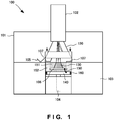
- A three-dimensional laminating and shaping
apparatus 100 according to the first embodiment of the present invention will be explained with reference toFig. 1 . The three-dimensional laminating and shapingapparatus 100 is a powder bed type apparatus. The three-dimensional laminating and shapingapparatus 100 irradiates a material spread on a shaping surface by a recoater or the like with an electron beam, thereby melting the material, solidifying the material, and completing laminating of one layer of the material. When completing the laminating of one layer, the three-dimensional laminating and shapingapparatus 100 moves down a shaping table by a height equivalent to the height of one layer, and spreads (recoats) the material of the next layer by the recoater or the like. After spreading the material, the three-dimensional laminating and shapingapparatus 100 irradiates the material with the electron beam, thereby melting the material, solidifying the material, and completing laminating of the material of the next one layer. The three-dimensional laminating and shapingapparatus 100 shapes a desired three-dimensional laminated and shaped object by repeating this operation. -
Fig. 4 is a view showing an example of the arrangement of a three-dimensional laminating and shaping apparatus according to the technical premise of the three-dimensional laminating and shaping apparatus according to this embodiment. - An
electron gun 402 is attached to avacuum vessel 401, and a shaping frame table (shaping box) 403 having a circular or square section is installed in thevacuum vessel 401. A Z-axis driving mechanism 404 is installed in a lower portion inside the shaping frame table 403, and capable of driving a powder table 440 in the Z direction by a rack-and-pinion, ball screw, or the like. - A heat-resistant
flexible seal 460 is formed in the gap between the shaping frame table 403 and powder table 440, thereby giving slidability and sealability by theflexible seal 460 and the inner sliding surface of the shaping frame table 403. A vacuum pump (not shown) evacuates thevacuum vessel 401 and maintains the interior of thevacuum vessel 401 in a vacuum state. - On the powder table 440, a shaping plate (base plate) 406 on which a three-dimensional laminated and
shaped object 430 is to be shaped is arranged in a state in which it is floated by a metal powder. To prevent electrical floating, theshaping plate 406 is grounded to the powder table 440 at a GND potential by aGND line 450. The three-dimensional laminated andshaped object 430 is shaped on theshaping plate 406. When shaping each layer, a linear funnel (recoater) 405 filled with a metal powder spreads the metal powder to almost the same height as that of the upper surface of the shaping frame table 403 (a spread powder 452). - A metal powder hopper (not shown) appropriately replenishes the metal powder to the
linear funnel 405. The three-dimensional laminated andshaped object 430 is constructed by two-dimensionally melting the spread (unsintered)powder 452 in a one-layer region of the three-dimensional laminated andshaped object 430 by an electron beam from theelectron gun 402, and overlaying the layers. A region of thepowder 452 spread on theshaping plate 406 except for the three-dimensional laminated andshaped object 430 is a powder (spread (calcined) powder) 451 calcined by the electron beam from theelectron gun 402, and has conductivity. - An
anti-deposition cover 420 is attached between the shaping surface andelectron gun 402, and prevents deposition of a metal vapor generated during shaping and deposition of metal sputtering by fireworks to the inner walls of thevacuum vessel 401. - The upper surface of the
shaping plate 406 covered with the metal powder in three directions is set at almost the same height as that of the upper surface of the shaping frame table 403, and a region slightly narrower than the whole region of the upper surface of theshaping plate 406 is irradiated with the electron beam from theelectron gun 402, thereby preheating the region to a temperature at which the metal powder is calcined. - When starting shaping, the Z-
axis driving mechanism 404 slightly moves down the powder table 440 such that the upper surface of theshaping plate 406 is arranged in a position slightly lower than the upper surface of the shaping frame table 403. ΔZ as this slight lowering is equivalent to the layer thickness in the Z direction after that. Thelinear funnel 405 filled with the metal powder is moved to the opposite side along the upper surface of theshaping plate 406, and the region slightly narrower than the shapingplate 406 on which the metal powder is spread by ΔZ is irradiated with the electron beam from theelectron gun 402, thereby heating the irradiated region, and reliably calcining the metal powder in the irradiated region. - In accordance with a two-dimensional shape obtained by slicing a prearranged designed three-dimensional laminated and shaped object (shaped model) at an interval of ΔZ, this two-dimensional region is melted by the electron beam from the
electron gun 402. After one layer is melted and solidified, the region slightly narrower than the shapingplate 406 is irradiated with the electron beam from theelectron gun 402 again, thereby heating the irradiated region, and preparing for spreading of the metal powder. - After the irradiated region is heated to a predetermined temperature, the electron beam is turned off, the Z-
axis driving mechanism 404 moves down the powder table 440 by ΔZ, thelinear funnel 405 is moved to the opposite side along the upper surface of the shaping frame table 403 again, and the metal powder is spread on the preceding layer by ΔZ. Then, the metal powder is reliably calcined by the electron beam from theelectron gun 402, and a two-dimensional-shape region corresponding to the layer is melted. The three-dimensional laminated and shapedobject 430 is shaped by repeating this process. -
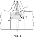
Fig. 5 is a view for explaining a mechanism of generating a smoke phenomenon by the three-dimensional laminating and shaping apparatus according to the technical premise of the three-dimensional laminating and shaping apparatus according to this embodiment.Fig. 5 is an enlarged view of a portion below theelectron gun 402 shown inFig. 4 . As shown inFig. 5 , when the electron beam is emitted for calcination or melting, a large amount of backscattered electrons and secondary electrons are generated from the irradiation position. The backscattered electrons collide against the inner walls of theanti-deposition cover 420 above the irradiation position, thereby further emitting backscattered electrons and secondary electrons. - As described above, a large amount of electrons exist above the shaping surface covered with the
anti-deposition cover 420, and an uncalcined metal powder is easily negatively charged because individual powder particles are electrically insulated by the surface oxide film. Therefore, if a charged metal powder forms due to insufficient calcination in a region to be irradiated with the electron beam, the charged metal powder is blown off to the outside unsintered region, and the charge balance breaks down in that region. If the charge balance breaks down, the repulsive force balance obtained by the electrostatic force also breaks down, and the metal powder particles scatter by repulsion, i.e., a smoke phenomenon occurs. To suppress this, a method expecting neutralization by generating gas ions by supplying a gas such as He gas is used. However, the smoke phenomenon still occurs if calcination is insufficient. -
Fig. 1 is a view showing the arrangement of the three-dimensional laminating and shaping apparatus according to this embodiment.Fig. 2 is a partially enlarged view showing the arrangement of the three-dimensional laminating and shaping apparatus according to this embodiment. The three-dimensional laminating and shapingapparatus 100 includes avacuum vessel 101, anelectron gun 102, a shaping frame table 103, a Z-axis driving mechanism 104, alinear funnel 105, ashaping plate 106, and ananti-deposition cover 107. Note that the three-dimensional laminating and shapingapparatus 100 will be explained below by taking a powder bed type shaping apparatus as an example. - The
charge shield 107 has an almost rectangular shape when viewed from above, and has an inside opening matching the shape of theshaping plate 106 so that an electron beam arrives on the upper surface of theshaping plate 106. The inside opening of thecharge shield 107 is positioned near the center of thecharge shield 107, and is a circular opening when the shapingplate 106 is circular, and a rectangular opening when the shapingplate 106 is rectangular. Also, thecharge shield 107 has the shape of a flat plate when viewed sideways. - The
charge shield 107 covers an unsintered region formed by anunsintered powder 152 in a region between the shaping frame table 103 and shapingplate 106, i.e., thecharge shield 107 is a shield mask. Also, since thecharge shield 107 has the opening, thecharge shield 107 does not cover a calcined region formed by acalcined powder 151 in the region between the shaping frame table 103 and shapingplate 106. Typical examples of the material of thecharge shield 107 are a conductive material such as a metal and an alloy such as stainless steel. The material is preferably the same kind of material as the metal powder as the material of a three-dimensional laminated and shapedobject 130. However, the material is not limited to these materials as long as the material can function as a shield. - A vertical driving mechanism (lifting mechanism) (not shown) is attached to the
charge shield 107. When irradiating theshaping plate 106 with an electron beam, thecharge shield 107 moves down onto the shaping surface. In addition, thecharge shield 107 is electrically grounded to GND although not shown. - The upper surface of the
shaping plate 106 covered with the metal powder in three directions is set at almost the same height as that of the upper surface of the shaping frame table 103, and thecharge shield 107 is moved down to the upper surface of theshaping plate 106, thereby covering the metal powder between the shapingplate 106 and shaping frame table 103. In this state, thecharge shield 107 is in contact with the metal powder. A region slightly narrower than the whole region of the upper surface of the shaping plate 106 (i.e., a region where the inside opening of thecharge shield 107 is not irradiated with the electron beam) is irradiated with the electron beam from theelectron gun 102, thereby preheating theshaping plate 106 to a temperature at which the metal powder is completely calcined. - When starting shaping, the Z-
axis driving mechanism 104 moves down the shaping table 140 so that the upper surface of theshaping plate 106 is arranged in a position slightly lower than the upper surface of the shaping frame table 103. ΔZ as this slight lowering is equivalent to the layer thickness in the Z direction after that. - The
charge shield 107 is moved up, the linear funnel (recoater) 105 filled with the metal powder is moved to the opposite side along the upper surface of theshaping plate 106, and the metal powder corresponding to ΔZ is recoated and spread on and around the shapingplate 106. After thelinear funnel 105 has moved to the outside of thecharge shield 107, thecharge shield 107 is moved down to the shaping surface again, thereby covering the metal powder between the shapingplate 106 and shaping frame table 103. - A region of the metal powder spread on the
shaping plate 106, in which the electron beam does not irradiate the inside opening of thecharge shield 107, is irradiated with the electron beam from theelectron gun 102, thereby heating the irradiated region, and reliably calcining the metal powder in the irradiated region. - In accordance with a two-dimensional shape obtained by slicing a prearranged designed three-dimensional laminated and shaped object (shaped model) at an interval of ΔZ, this two-dimensional-shape region is melted by the electron beam from the
electron gun 102. After one layer is melted and solidified, the region slightly narrower than the shapingplate 106 is irradiated with the electron beam from theelectron gun 102 again, thereby heating the irradiated region, and preparing for spreading of the metal powder. After the irradiated region is heated to a predetermined temperature, the electron beam is turned off, and thecharge shield 107 is moved up. - The Z-
axis driving mechanism 104 moves down the powder table 140 by ΔZ, thelinear funnel 105 is moved to the opposite side along the upper surface of the shaping frame table 103 again, the metal powder is spread on the preceding layer by ΔZ, and thecharge shield 107 is moved down to the shaping surface again. The region in which the electron beam does not irradiate the inside opening of thecharge shield 107 is irradiated with the electron beam from theelectron gun 102, thereby reliably calcining the newly spread metal powder, and a two-dimensional-shape region corresponding to the layer is melted. The three-dimensional laminating and shapingapparatus 100 shapes the three-dimensional laminated and shapedobject 130 by repeating this process. It is also possible to install or embed a heater in a mask portion outside the opening of thecharge shield 107, and make the temperature of the metal powder below the mask portion (inside the mask portion) equal to that of the shaping surface. This suppresses a decease (large change) in temperature of the shaping surface (metal powder) when the metal powder between the shapingplate 106 and shaping frame table 103 is covered with thecharge shield 107. - The material of the
charge shield 107 is desirably a conductive material having a low thermal conductivity and high heat resistance, and examples are titanium, a titanium alloy such as 64Ti, and stainless steel. Note that in this embodiment, the example in which thecharge shield 107 is vertically moved has been explained. However, the moving direction of thecharge shield 107 is not limited to this, and may also be moved in, e.g., the left-and-right direction or the direction of depth. -
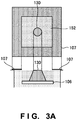
Fig. 3A shows a plan view and side view of thecharge shield 107 of the three-dimensional laminating and shaping apparatus according to this embodiment. The side surface shape of thecharge shield 107 is the shape of a flat plate and has a thickness of 0.5 mm or less, but the thickness may be smaller or larger than that. Note that in order to suppress an inflow of heat from the shaping surface, an inflow of heat from the shaping surface is suppressed by decreasing the thickness. -
Fig. 3B shows a plan view and side view of another example of thecharge shield 107 of the three-dimensional laminating and shaping apparatus according to this embodiment. Acontactor 171 is attached to the lower surface (the surface close to the shaping surface) of thecharge shield 107 shown inFig. 3B . Thecharge shield 107 has a shape which linearly comes in contact with a calcined region by thecontactor 171, and contacts the calcined region by thecontactor 171. Therefore, the contact area between thecharge shield 107 and calcined region decreases. Since the contact area between thecharge shield 107 and the shaping surface (calcined region) decreases, an inflow of heat from the shaping surface can be suppressed. -
Fig. 3C shows a plan view and side view of still another example of thecharge shield 107 of the three-dimensional laminating and shaping apparatus according to this embodiment. Referring toFig. 3C , in thecharge shield 107 having the flat plate shape shown inFig. 3A , a plurality of thin needle-like contactors are attached to the lower side of the flat plate, or a brush-like (comb-like) contactor is formed on the lower side of the flat plate, thereby further decreasing the contact area. An inflow of heat can be suppressed by thus decreasing the contact area between thecharge shield 107 and shaping surface. - Note that the shaping plate 106 (the shaping surface) is represented by a rectangular shape in
Figs. 3A to 3C , but the same shall apply even when the shapingplate 106 has a circular shape, polygonal shape, or the like. -
Fig. 6 is a flowchart for explaining the procedure of the three-dimensional laminating and shaping apparatus according to this embodiment. In step S601, the three-dimensional laminating and shapingapparatus 100 acquires shaping data of the three-dimensional laminated and shapedobject 130. In step S603, the three-dimensional laminating and shapingapparatus 100 recoats and spreads the metal powder on the shaping surface. In step S605, the three-dimensional laminating and shapingapparatus 100 moves down thecharge shield 107 and brings it into contact with the shaping surface. In step S607, the three-dimensional laminating and shapingapparatus 100 performs calcination by emitting an electron beam. In step S609, the three-dimensional laminating and shapingapparatus 100 performs final melting of the metal powder of one layer by emitting the electron beam based on the acquired shaping data. In step S611, the three-dimensional laminating and shapingapparatus 100 moves up thecharge shield 107, and recoats and spreads the metal powder on the shaping surface while moving thelinear funnel 105. In step S613, the three-dimensional laminating and shapingapparatus 100 performs calcination and final melting of the spread metal powder, thereby melting and solidifying the metal powder of one layer. In step S615, the three-dimensional laminating and shapingapparatus 100 determines whether shaping is complete. If the three-dimensional laminating and shapingapparatus 100 determines that shaping of the three-dimensional laminated and shapedobject 130 is complete (YES in step S615), the three-dimensional laminating and shapingapparatus 100 terminates the process. If the three-dimensional laminating and shapingapparatus 100 determines that shaping is not complete (NO in step S615), the three-dimensional laminating and shapingapparatus 100 repeats the process from step S611. - In this embodiment, when irradiating the shaping surface with an electron beam, an unsintered powder between the shaping plate and shaping frame table is masked with the charge shield. This makes it possible to suppress charge-up of the
unsintered powder 152 in an unsintered region, and prevent smoke. - Next, a three-dimensional laminating and shaping apparatus according to the second embodiment of the present invention will be explained with reference to
Fig. 7. Fig. 7 is a partial enlarged view for explaining the arrangement of a three-dimensional laminating and shapingapparatus 700 according to this embodiment. In the first embodiment, thecharge shield 107 is vertically moved. In this embodiment, as shown inFig. 7 , a charge shield (shield plate) 707 having fulcrums (rotational shafts) on the four sides is so attached as to hang toward a shaping surface. The four corners overlap each other when thecharge shield 707 is in contact with the shaping surface, so an unsintered region cannot be seen from above. A vacuum compatible motor or vacuum incompatible motor controls the rotational angle of the rotational shaft. When alinear funnel 105 as a material recoater spreads a metal powder on the shaping surface, thecharge shield 707 pivots on the rotational shafts and moves up. - In this embodiment, the apparatus configuration can be simplified because the charge shield is moved by the rotational shafts. Also, when irradiating the shaping surface with an electron beam, the charge shield as a conductive material masks an unsintered powder between a shaping plate and shaping frame table. This makes it possible to suppress charge-up of an
unsintered powder 152 in an unsintered region, and prevent smoke. - A three-dimensional laminating and shaping apparatus according to the third embodiment of the present invention will be explained below with reference to
Fig. 8. Fig. 8 is a partially enlarged view for explaining the arrangement of a three-dimensional laminating and shapingapparatus 800 according to this embodiment. The three-dimensional laminating and shapingapparatus 800 includes alinear funnel 805 and acharge shield 807. Also, thelinear funnel 805 has a translation cam (driver) 853, and thecharge shield 807 has a translation cam (follower) 873. - In this embodiment, when the
linear funnel 805 spreads a metal powder, thecharge shield 807 moves up in synchronism with the movement of thelinear funnel 805. In this case, an unsintered region is always covered with thecharge shield 807. When thelinear funnel 805 spreads the metal powder on a shaping surface, thetranslation cam 853 of thelinear funnel 805 pushes up thetranslation cam 873 of thecharge shield 807. That is, thecharge shield 807 vertically moves in accordance with the movement of thelinear funnel 805 having thetranslation cam 853. - Accordingly, the
charge shield 807 leaves the shaping surface only when thelinear funnel 805 passes over the shaping surface. Note that in order to decrease the friction between thetranslation cams - In the arrangement as described above, the
charge shield 807 covers an unsintered region except when spreading the metal powder. To implement failsafe, however, it is also possible to link control of an electron beam and control of thecharge shield 807, and enable emission of the electron beam only when the shaping surface is covered with thecharge shield 807. Whether thecharge shield 807 has reached the shaping surface can mechanically be detected by using a limit switch or the like. - In this embodiment, the linear funnel and charge shield have the translation cams. Since this makes a charge shield lifting mechanism unnecessary, it is possible to simplify the apparatus configuration, and easily synchronize the movements of the linear funnel and charge shield. Also, when irradiating the shaping surface with an electron beam, the charge shield as a conductive material masks an unsintered powder between the shaping plate and shaping frame table. This makes it possible to suppress charge-up of the unsintered powder in an unsintered region, and prevent smoke.
- While the present invention has been described with reference to exemplary embodiments, it is to be understood that the invention is not limited to the disclosed exemplary embodiments. The scope of the following claims is to be accorded the broadest interpretation so as to encompass all such modifications and equivalent structures and functions.
- The present invention is applicable to a system including a plurality of devices or a single apparatus. The present invention is also applicable even when an information processing program for implementing the functions of the embodiments is supplied to the system or apparatus directly or from a remote site. Hence, the present invention also incorporates the program installed in a computer to implement the functions of the present invention by the computer, a medium storing the program, and a WWW (World Wide Web) server that causes a user to download the program. Especially, the present invention incorporates at least a non-transitory computer readable medium storing a program that causes a computer to execute processing steps included in the above-described embodiments.
Claims (9)
- A three-dimensional laminating and shaping apparatus comprising:a material recoater that recoats a material of a three-dimensional laminated and shaped object onto a shaping surface on which the three-dimensional laminated and shaped object is to be shaped;an electron gun that generates an electron beam; anda shield that shields the material recoated on the shaping surface when irradiating the material with the electron beam.
- The three-dimensional laminating and shaping apparatus according to claim 1, further comprising a vertical driver that vertically moves said shield.
- The three-dimensional laminating and shaping apparatus according to claim 1, wherein said shield is a flat plate that pivots on a fulcrum.
- The three-dimensional laminating and shaping apparatus according to claim 1, wherein
said material recoater includes a translation cam, and
said shield vertically moves in accordance with a movement of said material recoater. - The three-dimensional laminating and shaping apparatus according to any one of claims 1 to 4, wherein said shield shields an unsintered region of the material recoated on the shaping surface, which is not to be sintered by the electron beam.
- The three-dimensional laminating and shaping apparatus according to any one of claims 1 to 5, wherein said shield includes a heater.
- The three-dimensional laminating and shaping apparatus according to any one of claims 1 to 6, wherein said shield comprises a rectangular or circular flat plate, and has an opening near a center.
- A three-dimensional laminating and shaping apparatus control method comprising:causing a material recoater to recoat a material of a three-dimensional laminated and shaped object onto a shaping surface on which the three-dimensional laminated and shaped object is to be shaped;causing an electron gun to generate an electron beam; andcausing a shield to shield the material recoated on the shaping surface when irradiating the material with the electron beam.
- A three-dimensional laminating and shaping apparatus control program for causing a computer to execute a method, comprising:causing a material recoater to recoat a material of a three-dimensional laminated and shaped object onto a shaping surface on which the three-dimensional laminated and shaped object is to be shaped;causing an electron gun to generate an electron beam; andcausing a shield to shield the material recoated on the shaping surface when irradiating the material with the electron beam.
Applications Claiming Priority (1)
| Application Number | Priority Date | Filing Date | Title |
|---|---|---|---|
| PCT/JP2016/059642 WO2017163402A1 (en) | 2016-03-25 | 2016-03-25 | Three-dimensional additive manufacturing device, control method for three-dimensional additive manufacturing device, and control program for three-dimensional additive manufacturing device |
Publications (3)
| Publication Number | Publication Date |
|---|---|
| EP3248716A1 true EP3248716A1 (en) | 2017-11-29 |
| EP3248716A4 EP3248716A4 (en) | 2018-08-29 |
| EP3248716B1 EP3248716B1 (en) | 2021-05-05 |
Family
ID=59901224
Family Applications (1)
| Application Number | Title | Priority Date | Filing Date |
|---|---|---|---|
| EP16825687.3A Active EP3248716B1 (en) | 2016-03-25 | 2016-03-25 | Three-dimensional additive manufacturing device, control method for three-dimensional additive manufacturing device, and control program for three-dimensional additive manufacturing device |
Country Status (4)
| Country | Link |
|---|---|
| US (1) | US10610957B2 (en) |
| EP (1) | EP3248716B1 (en) |
| JP (1) | JP6216464B1 (en) |
| WO (1) | WO2017163402A1 (en) |
Cited By (2)
| Publication number | Priority date | Publication date | Assignee | Title |
|---|---|---|---|---|
| US11059123B2 (en) * | 2017-04-28 | 2021-07-13 | Arcam Ab | Additive manufacturing of three-dimensional articles |
| WO2021113151A3 (en) * | 2019-12-03 | 2021-07-15 | Nikon Corporation | Additive manufacturing system with thermal control of material |
Families Citing this family (5)
| Publication number | Priority date | Publication date | Assignee | Title |
|---|---|---|---|---|
| US11167375B2 (en) | 2018-08-10 | 2021-11-09 | The Research Foundation For The State University Of New York | Additive manufacturing processes and additively manufactured products |
| WO2020059060A1 (en) * | 2018-09-19 | 2020-03-26 | 技術研究組合次世代3D積層造形技術総合開発機構 | Evaluation method for powder for metal additive manufacturing, evaluation program, manufacturing method, information processing device, and metal additive manufacturing device |
| JP7008669B2 (en) * | 2019-09-09 | 2022-01-25 | 日本電子株式会社 | 3D laminated modeling device and 3D laminated modeling method |
| US11925981B2 (en) | 2020-06-29 | 2024-03-12 | Arcam Ab | Method, apparatus and control unit for selectively sintering a powder layer in additive manufacturing processes to achieve a future, desired heat conductivity |
| JP7457613B2 (en) | 2020-09-14 | 2024-03-28 | 日本電子株式会社 | 3D additive manufacturing device and 3D additive manufacturing method |
Family Cites Families (11)
| Publication number | Priority date | Publication date | Assignee | Title |
|---|---|---|---|---|
| DE2211597C3 (en) * | 1972-03-10 | 1975-07-10 | Steigerwald Strahltechnik Gmbh, 8000 Muenchen | Device for keeping the beam path and the immediate vicinity of the beam path of a beam of an energy beam material processing machine free of interfering matter |
| US4976843A (en) * | 1990-02-02 | 1990-12-11 | Micrion Corporation | Particle beam shielding |
| JPH06136520A (en) * | 1992-10-23 | 1994-05-17 | Matsushita Electric Ind Co Ltd | Method for producing thin film and device therefor |
| US6326635B1 (en) * | 1999-07-30 | 2001-12-04 | Etec Systems, Inc. | Minimization of electron fogging in electron beam lithography |
| US20040262261A1 (en) * | 2003-06-27 | 2004-12-30 | Fink Jeffrey E. | Methods and systems for creating layer-formed plastic elements with improved properties |
| JP5019158B2 (en) * | 2006-10-25 | 2012-09-05 | 株式会社島津製作所 | Electron beam scanning method, electron beam scanning apparatus, and TFT array inspection apparatus |
| DE102006055054A1 (en) * | 2006-11-22 | 2008-05-29 | Eos Gmbh Electro Optical Systems | Apparatus for layering a three-dimensional object |
| KR101491678B1 (en) | 2007-05-15 | 2015-02-09 | 아르켐 에이비 | Method and Device for Producing Three-Dimensional Objects |
| DE102012012363A1 (en) * | 2012-06-22 | 2013-12-24 | Voxeljet Technology Gmbh | Apparatus for building up a layer body with a storage or filling container movable along the discharge container |
| JP2015175012A (en) | 2014-03-13 | 2015-10-05 | 日本電子株式会社 | Three-dimensional lamination molding device and method |
| US20180169938A1 (en) | 2015-11-13 | 2018-06-21 | Technology Research Association For Future Additive Manufacturing | Three-dimensional laminating and shaping apparatus, method of manufacturing three-dimensional laminating and shaping apparatus, and program for manufacturing three-dimensional laminating and shaping apparatus |
-
2016
- 2016-03-25 EP EP16825687.3A patent/EP3248716B1/en active Active
- 2016-03-25 WO PCT/JP2016/059642 patent/WO2017163402A1/en active Application Filing
- 2016-03-25 JP JP2016547110A patent/JP6216464B1/en active Active
- 2016-03-25 US US15/122,661 patent/US10610957B2/en active Active
Cited By (3)
| Publication number | Priority date | Publication date | Assignee | Title |
|---|---|---|---|---|
| US11059123B2 (en) * | 2017-04-28 | 2021-07-13 | Arcam Ab | Additive manufacturing of three-dimensional articles |
| EP3615247B1 (en) * | 2017-04-28 | 2021-07-21 | Arcam Ab | Electron beam melting apparatus for forming three-dimensional articles and method of manufacturing of said articles |
| WO2021113151A3 (en) * | 2019-12-03 | 2021-07-15 | Nikon Corporation | Additive manufacturing system with thermal control of material |
Also Published As
| Publication number | Publication date |
|---|---|
| JPWO2017163402A1 (en) | 2018-03-29 |
| EP3248716B1 (en) | 2021-05-05 |
| WO2017163402A1 (en) | 2017-09-28 |
| US10610957B2 (en) | 2020-04-07 |
| JP6216464B1 (en) | 2017-10-18 |
| US20180147653A1 (en) | 2018-05-31 |
| EP3248716A4 (en) | 2018-08-29 |
Similar Documents
| Publication | Publication Date | Title |
|---|---|---|
| EP3248716B1 (en) | Three-dimensional additive manufacturing device, control method for three-dimensional additive manufacturing device, and control program for three-dimensional additive manufacturing device | |
| EP3248717B1 (en) | 3d additive manufacturing device, control method for 3d additive manufacturing device, and control program for 3d additive manufacturing device | |
| EP2937163B1 (en) | Method for additive manufacturing | |
| EP3705207B1 (en) | Additive manufacturing device and additive manufacturing method | |
| JP6273578B2 (en) | Three-dimensional additive manufacturing apparatus and three-dimensional additive manufacturing method | |
| CN111182985B (en) | Three-dimensional modeling apparatus and three-dimensional modeling method | |
| WO2018193744A1 (en) | Three-dimensional manufacturing device | |
| EP3693164B1 (en) | Three-dimensional shaping device and three-dimensional shaping method | |
| JP6866931B2 (en) | 3D modeling device and 3D modeling method | |
| JP2023115028A (en) | Additive manufacturing device and additive manufacturing method | |
| US20230014614A1 (en) | Three-Dimensional Powder Bed Fusion Additive Manufacturing Apparatus and Three-Dimensional Powder Bed Fusion Additive Manufacturing Method | |
| JP7384366B2 (en) | Powder bed preheating | |
| EP4056303A1 (en) | Three-dimensional powder bed fusion additive manufacturing apparatus and three-dimensional powder bed fusion additive manufacturing method |
Legal Events
| Date | Code | Title | Description |
|---|---|---|---|
| STAA | Information on the status of an ep patent application or granted ep patent |
Free format text: STATUS: UNKNOWN |
|
| STAA | Information on the status of an ep patent application or granted ep patent |
Free format text: STATUS: THE INTERNATIONAL PUBLICATION HAS BEEN MADE |
|
| PUAI | Public reference made under article 153(3) epc to a published international application that has entered the european phase |
Free format text: ORIGINAL CODE: 0009012 |
|
| STAA | Information on the status of an ep patent application or granted ep patent |
Free format text: STATUS: REQUEST FOR EXAMINATION WAS MADE |
|
| 17P | Request for examination filed |
Effective date: 20170123 |
|
| AK | Designated contracting states |
Kind code of ref document: A1 Designated state(s): AL AT BE BG CH CY CZ DE DK EE ES FI FR GB GR HR HU IE IS IT LI LT LU LV MC MK MT NL NO PL PT RO RS SE SI SK SM TR |
|
| AX | Request for extension of the european patent |
Extension state: BA ME |
|
| DAV | Request for validation of the european patent (deleted) | ||
| DAX | Request for extension of the european patent (deleted) | ||
| R17P | Request for examination filed (corrected) |
Effective date: 20170123 |
|
| A4 | Supplementary search report drawn up and despatched |
Effective date: 20180730 |
|
| RIC1 | Information provided on ipc code assigned before grant |
Ipc: B33Y 30/00 20150101ALI20180724BHEP Ipc: B22F 3/105 20060101AFI20180724BHEP Ipc: B22F 3/16 20060101ALI20180724BHEP Ipc: B33Y 50/00 20150101ALI20180724BHEP |
|
| STAA | Information on the status of an ep patent application or granted ep patent |
Free format text: STATUS: EXAMINATION IS IN PROGRESS |
|
| 17Q | First examination report despatched |
Effective date: 20190712 |
|
| RIC1 | Information provided on ipc code assigned before grant |
Ipc: B22F 3/105 20060101AFI20200922BHEP Ipc: B33Y 30/00 20150101ALI20200922BHEP |
|
| RIC1 | Information provided on ipc code assigned before grant |
Ipc: B33Y 50/02 20150101ALI20201027BHEP Ipc: B33Y 30/00 20150101ALI20201027BHEP Ipc: B22F 3/105 20060101AFI20201027BHEP |
|
| GRAP | Despatch of communication of intention to grant a patent |
Free format text: ORIGINAL CODE: EPIDOSNIGR1 |
|
| STAA | Information on the status of an ep patent application or granted ep patent |
Free format text: STATUS: GRANT OF PATENT IS INTENDED |
|
| INTG | Intention to grant announced |
Effective date: 20201214 |
|
| GRAS | Grant fee paid |
Free format text: ORIGINAL CODE: EPIDOSNIGR3 |
|
| GRAA | (expected) grant |
Free format text: ORIGINAL CODE: 0009210 |
|
| STAA | Information on the status of an ep patent application or granted ep patent |
Free format text: STATUS: THE PATENT HAS BEEN GRANTED |
|
| AK | Designated contracting states |
Kind code of ref document: B1 Designated state(s): AL AT BE BG CH CY CZ DE DK EE ES FI FR GB GR HR HU IE IS IT LI LT LU LV MC MK MT NL NO PL PT RO RS SE SI SK SM TR |
|
| REG | Reference to a national code |
Ref country code: GB Ref legal event code: FG4D |
|
| REG | Reference to a national code |
Ref country code: CH Ref legal event code: EP |
|
| REG | Reference to a national code |
Ref country code: AT Ref legal event code: REF Ref document number: 1389173 Country of ref document: AT Kind code of ref document: T Effective date: 20210515 |
|
| REG | Reference to a national code |
Ref country code: IE Ref legal event code: FG4D |
|
| REG | Reference to a national code |
Ref country code: DE Ref legal event code: R096 Ref document number: 602016057525 Country of ref document: DE |
|
| REG | Reference to a national code |
Ref country code: LT Ref legal event code: MG9D |
|
| REG | Reference to a national code |
Ref country code: AT Ref legal event code: MK05 Ref document number: 1389173 Country of ref document: AT Kind code of ref document: T Effective date: 20210505 |
|
| PG25 | Lapsed in a contracting state [announced via postgrant information from national office to epo] |
Ref country code: LT Free format text: LAPSE BECAUSE OF FAILURE TO SUBMIT A TRANSLATION OF THE DESCRIPTION OR TO PAY THE FEE WITHIN THE PRESCRIBED TIME-LIMIT Effective date: 20210505 Ref country code: FI Free format text: LAPSE BECAUSE OF FAILURE TO SUBMIT A TRANSLATION OF THE DESCRIPTION OR TO PAY THE FEE WITHIN THE PRESCRIBED TIME-LIMIT Effective date: 20210505 Ref country code: HR Free format text: LAPSE BECAUSE OF FAILURE TO SUBMIT A TRANSLATION OF THE DESCRIPTION OR TO PAY THE FEE WITHIN THE PRESCRIBED TIME-LIMIT Effective date: 20210505 Ref country code: BG Free format text: LAPSE BECAUSE OF FAILURE TO SUBMIT A TRANSLATION OF THE DESCRIPTION OR TO PAY THE FEE WITHIN THE PRESCRIBED TIME-LIMIT Effective date: 20210805 Ref country code: AT Free format text: LAPSE BECAUSE OF FAILURE TO SUBMIT A TRANSLATION OF THE DESCRIPTION OR TO PAY THE FEE WITHIN THE PRESCRIBED TIME-LIMIT Effective date: 20210505 |
|
| PG25 | Lapsed in a contracting state [announced via postgrant information from national office to epo] |
Ref country code: LV Free format text: LAPSE BECAUSE OF FAILURE TO SUBMIT A TRANSLATION OF THE DESCRIPTION OR TO PAY THE FEE WITHIN THE PRESCRIBED TIME-LIMIT Effective date: 20210505 Ref country code: GR Free format text: LAPSE BECAUSE OF FAILURE TO SUBMIT A TRANSLATION OF THE DESCRIPTION OR TO PAY THE FEE WITHIN THE PRESCRIBED TIME-LIMIT Effective date: 20210806 Ref country code: IS Free format text: LAPSE BECAUSE OF FAILURE TO SUBMIT A TRANSLATION OF THE DESCRIPTION OR TO PAY THE FEE WITHIN THE PRESCRIBED TIME-LIMIT Effective date: 20210905 Ref country code: SE Free format text: LAPSE BECAUSE OF FAILURE TO SUBMIT A TRANSLATION OF THE DESCRIPTION OR TO PAY THE FEE WITHIN THE PRESCRIBED TIME-LIMIT Effective date: 20210505 Ref country code: RS Free format text: LAPSE BECAUSE OF FAILURE TO SUBMIT A TRANSLATION OF THE DESCRIPTION OR TO PAY THE FEE WITHIN THE PRESCRIBED TIME-LIMIT Effective date: 20210505 Ref country code: PT Free format text: LAPSE BECAUSE OF FAILURE TO SUBMIT A TRANSLATION OF THE DESCRIPTION OR TO PAY THE FEE WITHIN THE PRESCRIBED TIME-LIMIT Effective date: 20210906 Ref country code: PL Free format text: LAPSE BECAUSE OF FAILURE TO SUBMIT A TRANSLATION OF THE DESCRIPTION OR TO PAY THE FEE WITHIN THE PRESCRIBED TIME-LIMIT Effective date: 20210505 Ref country code: NO Free format text: LAPSE BECAUSE OF FAILURE TO SUBMIT A TRANSLATION OF THE DESCRIPTION OR TO PAY THE FEE WITHIN THE PRESCRIBED TIME-LIMIT Effective date: 20210805 |
|
| REG | Reference to a national code |
Ref country code: NL Ref legal event code: MP Effective date: 20210505 |
|
| PG25 | Lapsed in a contracting state [announced via postgrant information from national office to epo] |
Ref country code: NL Free format text: LAPSE BECAUSE OF FAILURE TO SUBMIT A TRANSLATION OF THE DESCRIPTION OR TO PAY THE FEE WITHIN THE PRESCRIBED TIME-LIMIT Effective date: 20210505 |
|
| REG | Reference to a national code |
Ref country code: DE Ref legal event code: R081 Ref document number: 602016057525 Country of ref document: DE Owner name: JEOL LTD., AKISHIMA-SHI, JP Free format text: FORMER OWNER: TECHNOLOGY RESEARCH ASSOCIATION FOR FUTURE ADDITIVE MANUFACTURING, TOKYO, JP |
|
| PG25 | Lapsed in a contracting state [announced via postgrant information from national office to epo] |
Ref country code: DK Free format text: LAPSE BECAUSE OF FAILURE TO SUBMIT A TRANSLATION OF THE DESCRIPTION OR TO PAY THE FEE WITHIN THE PRESCRIBED TIME-LIMIT Effective date: 20210505 Ref country code: CZ Free format text: LAPSE BECAUSE OF FAILURE TO SUBMIT A TRANSLATION OF THE DESCRIPTION OR TO PAY THE FEE WITHIN THE PRESCRIBED TIME-LIMIT Effective date: 20210505 Ref country code: EE Free format text: LAPSE BECAUSE OF FAILURE TO SUBMIT A TRANSLATION OF THE DESCRIPTION OR TO PAY THE FEE WITHIN THE PRESCRIBED TIME-LIMIT Effective date: 20210505 Ref country code: RO Free format text: LAPSE BECAUSE OF FAILURE TO SUBMIT A TRANSLATION OF THE DESCRIPTION OR TO PAY THE FEE WITHIN THE PRESCRIBED TIME-LIMIT Effective date: 20210505 Ref country code: ES Free format text: LAPSE BECAUSE OF FAILURE TO SUBMIT A TRANSLATION OF THE DESCRIPTION OR TO PAY THE FEE WITHIN THE PRESCRIBED TIME-LIMIT Effective date: 20210505 Ref country code: SK Free format text: LAPSE BECAUSE OF FAILURE TO SUBMIT A TRANSLATION OF THE DESCRIPTION OR TO PAY THE FEE WITHIN THE PRESCRIBED TIME-LIMIT Effective date: 20210505 Ref country code: SM Free format text: LAPSE BECAUSE OF FAILURE TO SUBMIT A TRANSLATION OF THE DESCRIPTION OR TO PAY THE FEE WITHIN THE PRESCRIBED TIME-LIMIT Effective date: 20210505 |
|
| REG | Reference to a national code |
Ref country code: GB Ref legal event code: 732E Free format text: REGISTERED BETWEEN 20220106 AND 20220112 |
|
| REG | Reference to a national code |
Ref country code: DE Ref legal event code: R097 Ref document number: 602016057525 Country of ref document: DE |
|
| PLBE | No opposition filed within time limit |
Free format text: ORIGINAL CODE: 0009261 |
|
| STAA | Information on the status of an ep patent application or granted ep patent |
Free format text: STATUS: NO OPPOSITION FILED WITHIN TIME LIMIT |
|
| 26N | No opposition filed |
Effective date: 20220208 |
|
| PG25 | Lapsed in a contracting state [announced via postgrant information from national office to epo] |
Ref country code: IS Free format text: LAPSE BECAUSE OF FAILURE TO SUBMIT A TRANSLATION OF THE DESCRIPTION OR TO PAY THE FEE WITHIN THE PRESCRIBED TIME-LIMIT Effective date: 20210905 Ref country code: AL Free format text: LAPSE BECAUSE OF FAILURE TO SUBMIT A TRANSLATION OF THE DESCRIPTION OR TO PAY THE FEE WITHIN THE PRESCRIBED TIME-LIMIT Effective date: 20210505 |
|
| PG25 | Lapsed in a contracting state [announced via postgrant information from national office to epo] |
Ref country code: IT Free format text: LAPSE BECAUSE OF FAILURE TO SUBMIT A TRANSLATION OF THE DESCRIPTION OR TO PAY THE FEE WITHIN THE PRESCRIBED TIME-LIMIT Effective date: 20210505 |
|
| PG25 | Lapsed in a contracting state [announced via postgrant information from national office to epo] |
Ref country code: MC Free format text: LAPSE BECAUSE OF FAILURE TO SUBMIT A TRANSLATION OF THE DESCRIPTION OR TO PAY THE FEE WITHIN THE PRESCRIBED TIME-LIMIT Effective date: 20210505 |
|
| REG | Reference to a national code |
Ref country code: CH Ref legal event code: PL |
|
| REG | Reference to a national code |
Ref country code: BE Ref legal event code: MM Effective date: 20220331 |
|
| PG25 | Lapsed in a contracting state [announced via postgrant information from national office to epo] |
Ref country code: LU Free format text: LAPSE BECAUSE OF NON-PAYMENT OF DUE FEES Effective date: 20220325 Ref country code: LI Free format text: LAPSE BECAUSE OF NON-PAYMENT OF DUE FEES Effective date: 20220331 Ref country code: IE Free format text: LAPSE BECAUSE OF NON-PAYMENT OF DUE FEES Effective date: 20220325 Ref country code: CH Free format text: LAPSE BECAUSE OF NON-PAYMENT OF DUE FEES Effective date: 20220331 |
|
| PG25 | Lapsed in a contracting state [announced via postgrant information from national office to epo] |
Ref country code: BE Free format text: LAPSE BECAUSE OF NON-PAYMENT OF DUE FEES Effective date: 20220331 |
|
| PGFP | Annual fee paid to national office [announced via postgrant information from national office to epo] |
Ref country code: FR Payment date: 20230324 Year of fee payment: 8 |
|
| PG25 | Lapsed in a contracting state [announced via postgrant information from national office to epo] |
Ref country code: HU Free format text: LAPSE BECAUSE OF FAILURE TO SUBMIT A TRANSLATION OF THE DESCRIPTION OR TO PAY THE FEE WITHIN THE PRESCRIBED TIME-LIMIT; INVALID AB INITIO Effective date: 20160325 |
|
| PG25 | Lapsed in a contracting state [announced via postgrant information from national office to epo] |
Ref country code: MK Free format text: LAPSE BECAUSE OF FAILURE TO SUBMIT A TRANSLATION OF THE DESCRIPTION OR TO PAY THE FEE WITHIN THE PRESCRIBED TIME-LIMIT Effective date: 20210505 Ref country code: CY Free format text: LAPSE BECAUSE OF FAILURE TO SUBMIT A TRANSLATION OF THE DESCRIPTION OR TO PAY THE FEE WITHIN THE PRESCRIBED TIME-LIMIT Effective date: 20210505 |
|
| PGFP | Annual fee paid to national office [announced via postgrant information from national office to epo] |
Ref country code: DE Payment date: 20240320 Year of fee payment: 9 Ref country code: GB Payment date: 20240320 Year of fee payment: 9 |