EP3247547B1 - Methods for gel reduction in polyolefins - Google Patents
Methods for gel reduction in polyolefins Download PDFInfo
- Publication number
- EP3247547B1 EP3247547B1 EP16704962.6A EP16704962A EP3247547B1 EP 3247547 B1 EP3247547 B1 EP 3247547B1 EP 16704962 A EP16704962 A EP 16704962A EP 3247547 B1 EP3247547 B1 EP 3247547B1
- Authority
- EP
- European Patent Office
- Prior art keywords
- mesh
- melt
- size
- screen
- extruder
- Prior art date
- Legal status (The legal status is an assumption and is not a legal conclusion. Google has not performed a legal analysis and makes no representation as to the accuracy of the status listed.)
- Active
Links
- 238000000034 method Methods 0.000 title claims description 68
- 229920000098 polyolefin Polymers 0.000 title claims description 57
- 230000009467 reduction Effects 0.000 title claims description 17
- 239000000155 melt Substances 0.000 claims description 62
- 239000000499 gel Substances 0.000 claims description 57
- 239000000178 monomer Substances 0.000 claims description 15
- VGGSQFUCUMXWEO-UHFFFAOYSA-N Ethene Chemical compound C=C VGGSQFUCUMXWEO-UHFFFAOYSA-N 0.000 claims description 14
- 239000005977 Ethylene Substances 0.000 claims description 14
- 239000008188 pellet Substances 0.000 claims description 11
- 229920005672 polyolefin resin Polymers 0.000 claims description 9
- 125000004432 carbon atom Chemical group C* 0.000 claims description 8
- 230000002829 reductive effect Effects 0.000 claims description 8
- 239000004711 α-olefin Substances 0.000 claims description 8
- 238000002844 melting Methods 0.000 claims description 5
- 230000008018 melting Effects 0.000 claims description 5
- 229920003023 plastic Polymers 0.000 claims description 5
- 239000004033 plastic Substances 0.000 claims description 5
- -1 polyethylene Polymers 0.000 description 111
- 239000003054 catalyst Substances 0.000 description 78
- 229920000642 polymer Polymers 0.000 description 38
- 239000000203 mixture Substances 0.000 description 33
- 239000000463 material Substances 0.000 description 30
- 150000001875 compounds Chemical class 0.000 description 29
- 230000008569 process Effects 0.000 description 29
- 238000006116 polymerization reaction Methods 0.000 description 24
- 125000001183 hydrocarbyl group Chemical group 0.000 description 23
- 238000001125 extrusion Methods 0.000 description 22
- 239000003446 ligand Substances 0.000 description 21
- 125000000217 alkyl group Chemical group 0.000 description 20
- 239000007789 gas Substances 0.000 description 20
- 239000012190 activator Substances 0.000 description 18
- 125000003545 alkoxy group Chemical group 0.000 description 18
- 239000012968 metallocene catalyst Substances 0.000 description 18
- 229910052751 metal Inorganic materials 0.000 description 17
- 239000002184 metal Substances 0.000 description 17
- 229920005989 resin Polymers 0.000 description 17
- 239000011347 resin Substances 0.000 description 17
- 125000004429 atom Chemical group 0.000 description 16
- 239000000047 product Substances 0.000 description 16
- ZSWFCLXCOIISFI-UHFFFAOYSA-N cyclopentadiene Chemical compound C1C=CC=C1 ZSWFCLXCOIISFI-UHFFFAOYSA-N 0.000 description 15
- 150000001336 alkenes Chemical class 0.000 description 14
- 125000003118 aryl group Chemical group 0.000 description 13
- 239000004698 Polyethylene Substances 0.000 description 12
- 125000003342 alkenyl group Chemical group 0.000 description 12
- 125000000304 alkynyl group Chemical group 0.000 description 12
- 125000001072 heteroaryl group Chemical group 0.000 description 12
- 229920000573 polyethylene Polymers 0.000 description 12
- 125000002877 alkyl aryl group Chemical group 0.000 description 11
- 238000006243 chemical reaction Methods 0.000 description 11
- 125000000058 cyclopentadienyl group Chemical group C1(=CC=CC1)* 0.000 description 11
- 125000004404 heteroalkyl group Chemical group 0.000 description 11
- 125000005842 heteroatom Chemical group 0.000 description 11
- QQONPFPTGQHPMA-UHFFFAOYSA-N propylene Natural products CC=C QQONPFPTGQHPMA-UHFFFAOYSA-N 0.000 description 10
- 125000004805 propylene group Chemical group [H]C([H])([H])C([H])([*:1])C([H])([H])[*:2] 0.000 description 10
- 125000001424 substituent group Chemical group 0.000 description 10
- 239000002245 particle Substances 0.000 description 9
- 239000007787 solid Substances 0.000 description 9
- 125000004104 aryloxy group Chemical group 0.000 description 8
- 230000007547 defect Effects 0.000 description 8
- 125000000623 heterocyclic group Chemical group 0.000 description 8
- 125000004051 hexyl group Chemical group [H]C([H])([H])C([H])([H])C([H])([H])C([H])([H])C([H])([H])C([H])([H])* 0.000 description 8
- 239000001257 hydrogen Substances 0.000 description 8
- 229910052739 hydrogen Inorganic materials 0.000 description 8
- 230000000670 limiting effect Effects 0.000 description 8
- 239000007788 liquid Substances 0.000 description 8
- 125000001997 phenyl group Chemical group [H]C1=C([H])C([H])=C(*)C([H])=C1[H] 0.000 description 8
- 229920001155 polypropylene Polymers 0.000 description 8
- 229910052710 silicon Inorganic materials 0.000 description 8
- 239000000243 solution Substances 0.000 description 8
- UFHFLCQGNIYNRP-UHFFFAOYSA-N Hydrogen Chemical compound [H][H] UFHFLCQGNIYNRP-UHFFFAOYSA-N 0.000 description 7
- VYPSYNLAJGMNEJ-UHFFFAOYSA-N Silicium dioxide Chemical compound O=[Si]=O VYPSYNLAJGMNEJ-UHFFFAOYSA-N 0.000 description 7
- 125000004414 alkyl thio group Chemical group 0.000 description 7
- 229910052799 carbon Inorganic materials 0.000 description 7
- 125000000753 cycloalkyl group Chemical group 0.000 description 7
- 150000004820 halides Chemical class 0.000 description 7
- 239000010936 titanium Substances 0.000 description 7
- IJGRMHOSHXDMSA-UHFFFAOYSA-N Atomic nitrogen Chemical compound N#N IJGRMHOSHXDMSA-UHFFFAOYSA-N 0.000 description 6
- 239000004743 Polypropylene Substances 0.000 description 6
- 239000000654 additive Substances 0.000 description 6
- 229910052782 aluminium Inorganic materials 0.000 description 6
- 150000001412 amines Chemical class 0.000 description 6
- 125000003710 aryl alkyl group Chemical group 0.000 description 6
- 125000005110 aryl thio group Chemical group 0.000 description 6
- 125000000707 boryl group Chemical group B* 0.000 description 6
- 125000004122 cyclic group Chemical group 0.000 description 6
- 229910052732 germanium Inorganic materials 0.000 description 6
- 125000000262 haloalkenyl group Chemical group 0.000 description 6
- 125000001188 haloalkyl group Chemical group 0.000 description 6
- 125000000232 haloalkynyl group Chemical group 0.000 description 6
- 229910052736 halogen Inorganic materials 0.000 description 6
- 238000002156 mixing Methods 0.000 description 6
- 229910052757 nitrogen Inorganic materials 0.000 description 6
- 125000001181 organosilyl group Chemical group [SiH3]* 0.000 description 6
- 229910052760 oxygen Inorganic materials 0.000 description 6
- 238000005453 pelletization Methods 0.000 description 6
- 150000003003 phosphines Chemical class 0.000 description 6
- 125000002924 primary amino group Chemical group [H]N([H])* 0.000 description 6
- 239000002904 solvent Substances 0.000 description 6
- 125000005017 substituted alkenyl group Chemical group 0.000 description 6
- 125000000547 substituted alkyl group Chemical group 0.000 description 6
- 125000004426 substituted alkynyl group Chemical group 0.000 description 6
- 125000003107 substituted aryl group Chemical group 0.000 description 6
- 229910052719 titanium Inorganic materials 0.000 description 6
- LIKMAJRDDDTEIG-UHFFFAOYSA-N 1-hexene Chemical compound CCCCC=C LIKMAJRDDDTEIG-UHFFFAOYSA-N 0.000 description 5
- 125000006539 C12 alkyl group Chemical group [H]C([H])([H])C([H])([H])C([H])([H])C([H])([H])C([H])([H])C([H])([H])C([H])([H])C([H])([H])C([H])([H])C([H])([H])C([H])([H])C([H])([H])* 0.000 description 5
- OKTJSMMVPCPJKN-UHFFFAOYSA-N Carbon Chemical compound [C] OKTJSMMVPCPJKN-UHFFFAOYSA-N 0.000 description 5
- RTAQQCXQSZGOHL-UHFFFAOYSA-N Titanium Chemical compound [Ti] RTAQQCXQSZGOHL-UHFFFAOYSA-N 0.000 description 5
- 125000002252 acyl group Chemical group 0.000 description 5
- 125000004442 acylamino group Chemical group 0.000 description 5
- 125000004423 acyloxy group Chemical group 0.000 description 5
- 125000004453 alkoxycarbonyl group Chemical group 0.000 description 5
- 125000005115 alkyl carbamoyl group Chemical group 0.000 description 5
- 150000001356 alkyl thiols Chemical class 0.000 description 5
- 125000003435 aroyl group Chemical group 0.000 description 5
- 125000005239 aroylamino group Chemical group 0.000 description 5
- 125000005161 aryl oxy carbonyl group Chemical group 0.000 description 5
- 125000000484 butyl group Chemical group [H]C([*])([H])C([H])([H])C([H])([H])C([H])([H])[H] 0.000 description 5
- 125000003917 carbamoyl group Chemical group [H]N([H])C(*)=O 0.000 description 5
- 229910052804 chromium Inorganic materials 0.000 description 5
- 239000011651 chromium Substances 0.000 description 5
- 125000005265 dialkylamine group Chemical group 0.000 description 5
- 125000005117 dialkylcarbamoyl group Chemical group 0.000 description 5
- 229920001903 high density polyethylene Polymers 0.000 description 5
- 239000004700 high-density polyethylene Substances 0.000 description 5
- 150000004678 hydrides Chemical class 0.000 description 5
- 125000002887 hydroxy group Chemical group [H]O* 0.000 description 5
- 238000004519 manufacturing process Methods 0.000 description 5
- 125000002496 methyl group Chemical group [H]C([H])([H])* 0.000 description 5
- 150000003254 radicals Chemical class 0.000 description 5
- 229920006395 saturated elastomer Polymers 0.000 description 5
- 229910052723 transition metal Inorganic materials 0.000 description 5
- 150000003624 transition metals Chemical class 0.000 description 5
- ZGEGCLOFRBLKSE-UHFFFAOYSA-N 1-Heptene Chemical compound CCCCCC=C ZGEGCLOFRBLKSE-UHFFFAOYSA-N 0.000 description 4
- AFFLGGQVNFXPEV-UHFFFAOYSA-N 1-decene Chemical compound CCCCCCCCC=C AFFLGGQVNFXPEV-UHFFFAOYSA-N 0.000 description 4
- CRSBERNSMYQZNG-UHFFFAOYSA-N 1-dodecene Chemical compound CCCCCCCCCCC=C CRSBERNSMYQZNG-UHFFFAOYSA-N 0.000 description 4
- GQEZCXVZFLOKMC-UHFFFAOYSA-N 1-hexadecene Chemical compound CCCCCCCCCCCCCCC=C GQEZCXVZFLOKMC-UHFFFAOYSA-N 0.000 description 4
- KWKAKUADMBZCLK-UHFFFAOYSA-N 1-octene Chemical compound CCCCCCC=C KWKAKUADMBZCLK-UHFFFAOYSA-N 0.000 description 4
- YBYIRNPNPLQARY-UHFFFAOYSA-N 1H-indene Natural products C1=CC=C2CC=CC2=C1 YBYIRNPNPLQARY-UHFFFAOYSA-N 0.000 description 4
- 125000000882 C2-C6 alkenyl group Chemical group 0.000 description 4
- VYZAMTAEIAYCRO-UHFFFAOYSA-N Chromium Chemical compound [Cr] VYZAMTAEIAYCRO-UHFFFAOYSA-N 0.000 description 4
- KRHYYFGTRYWZRS-UHFFFAOYSA-M Fluoride anion Chemical compound [F-] KRHYYFGTRYWZRS-UHFFFAOYSA-M 0.000 description 4
- XUIMIQQOPSSXEZ-UHFFFAOYSA-N Silicon Chemical compound [Si] XUIMIQQOPSSXEZ-UHFFFAOYSA-N 0.000 description 4
- XAGFODPZIPBFFR-UHFFFAOYSA-N aluminium Chemical compound [Al] XAGFODPZIPBFFR-UHFFFAOYSA-N 0.000 description 4
- 229910052796 boron Inorganic materials 0.000 description 4
- 229920001577 copolymer Polymers 0.000 description 4
- 239000012530 fluid Substances 0.000 description 4
- 125000003983 fluorenyl group Chemical group C1(=CC=CC=2C3=CC=CC=C3CC12)* 0.000 description 4
- 238000012685 gas phase polymerization Methods 0.000 description 4
- 150000002430 hydrocarbons Chemical class 0.000 description 4
- 125000003454 indenyl group Chemical group C1(C=CC2=CC=CC=C12)* 0.000 description 4
- 229910052809 inorganic oxide Inorganic materials 0.000 description 4
- 239000001301 oxygen Substances 0.000 description 4
- YWAKXRMUMFPDSH-UHFFFAOYSA-N pentene Chemical compound CCCC=C YWAKXRMUMFPDSH-UHFFFAOYSA-N 0.000 description 4
- 239000011148 porous material Substances 0.000 description 4
- 239000010703 silicon Substances 0.000 description 4
- 239000002002 slurry Substances 0.000 description 4
- PBKONEOXTCPAFI-UHFFFAOYSA-N 1,2,4-trichlorobenzene Chemical compound ClC1=CC=C(Cl)C(Cl)=C1 PBKONEOXTCPAFI-UHFFFAOYSA-N 0.000 description 3
- WSSSPWUEQFSQQG-UHFFFAOYSA-N 4-methyl-1-pentene Chemical compound CC(C)CC=C WSSSPWUEQFSQQG-UHFFFAOYSA-N 0.000 description 3
- ZOXJGFHDIHLPTG-UHFFFAOYSA-N Boron Chemical compound [B] ZOXJGFHDIHLPTG-UHFFFAOYSA-N 0.000 description 3
- VEXZGXHMUGYJMC-UHFFFAOYSA-M Chloride anion Chemical compound [Cl-] VEXZGXHMUGYJMC-UHFFFAOYSA-M 0.000 description 3
- GWEVSGVZZGPLCZ-UHFFFAOYSA-N Titan oxide Chemical compound O=[Ti]=O GWEVSGVZZGPLCZ-UHFFFAOYSA-N 0.000 description 3
- PNEYBMLMFCGWSK-UHFFFAOYSA-N aluminium oxide Inorganic materials [O-2].[O-2].[O-2].[Al+3].[Al+3] PNEYBMLMFCGWSK-UHFFFAOYSA-N 0.000 description 3
- QVGXLLKOCUKJST-UHFFFAOYSA-N atomic oxygen Chemical compound [O] QVGXLLKOCUKJST-UHFFFAOYSA-N 0.000 description 3
- 239000006229 carbon black Substances 0.000 description 3
- 239000003795 chemical substances by application Substances 0.000 description 3
- 239000003426 co-catalyst Substances 0.000 description 3
- 238000013461 design Methods 0.000 description 3
- 239000003085 diluting agent Substances 0.000 description 3
- 125000001495 ethyl group Chemical group [H]C([H])([H])C([H])([H])* 0.000 description 3
- 230000010006 flight Effects 0.000 description 3
- 125000003709 fluoroalkyl group Chemical group 0.000 description 3
- 125000004216 fluoromethyl group Chemical group [H]C([H])(F)* 0.000 description 3
- 229920001519 homopolymer Polymers 0.000 description 3
- 229930195733 hydrocarbon Natural products 0.000 description 3
- 238000011065 in-situ storage Methods 0.000 description 3
- 239000011777 magnesium Substances 0.000 description 3
- 238000005259 measurement Methods 0.000 description 3
- 230000007935 neutral effect Effects 0.000 description 3
- 230000003287 optical effect Effects 0.000 description 3
- 238000004806 packaging method and process Methods 0.000 description 3
- 239000011236 particulate material Substances 0.000 description 3
- 239000000843 powder Substances 0.000 description 3
- 125000001436 propyl group Chemical group [H]C([*])([H])C([H])([H])C([H])([H])[H] 0.000 description 3
- 229910052761 rare earth metal Inorganic materials 0.000 description 3
- 150000002910 rare earth metals Chemical class 0.000 description 3
- 239000000126 substance Substances 0.000 description 3
- 229910052717 sulfur Inorganic materials 0.000 description 3
- 239000000454 talc Substances 0.000 description 3
- 229910052623 talc Inorganic materials 0.000 description 3
- 238000012360 testing method Methods 0.000 description 3
- AHAREKHAZNPPMI-AATRIKPKSA-N (3e)-hexa-1,3-diene Chemical compound CC\C=C\C=C AHAREKHAZNPPMI-AATRIKPKSA-N 0.000 description 2
- PRBHEGAFLDMLAL-GQCTYLIASA-N (4e)-hexa-1,4-diene Chemical compound C\C=C\CC=C PRBHEGAFLDMLAL-GQCTYLIASA-N 0.000 description 2
- VYXHVRARDIDEHS-UHFFFAOYSA-N 1,5-cyclooctadiene Chemical compound C1CC=CCCC=C1 VYXHVRARDIDEHS-UHFFFAOYSA-N 0.000 description 2
- 239000004912 1,5-cyclooctadiene Substances 0.000 description 2
- VXNZUUAINFGPBY-UHFFFAOYSA-N 1-Butene Chemical compound CCC=C VXNZUUAINFGPBY-UHFFFAOYSA-N 0.000 description 2
- HECLRDQVFMWTQS-RGOKHQFPSA-N 1755-01-7 Chemical compound C1[C@H]2[C@@H]3CC=C[C@@H]3[C@@H]1C=C2 HECLRDQVFMWTQS-RGOKHQFPSA-N 0.000 description 2
- 125000003903 2-propenyl group Chemical group [H]C([*])([H])C([H])=C([H])[H] 0.000 description 2
- BBDKZWKEPDTENS-UHFFFAOYSA-N 4-Vinylcyclohexene Chemical compound C=CC1CCC=CC1 BBDKZWKEPDTENS-UHFFFAOYSA-N 0.000 description 2
- KLAWFKRMCIXRFS-UHFFFAOYSA-N 5-ethenylidenebicyclo[2.2.1]hept-2-ene Chemical compound C1C2C(=C=C)CC1C=C2 KLAWFKRMCIXRFS-UHFFFAOYSA-N 0.000 description 2
- KAKZBPTYRLMSJV-UHFFFAOYSA-N Butadiene Chemical compound C=CC=C KAKZBPTYRLMSJV-UHFFFAOYSA-N 0.000 description 2
- ZAMOUSCENKQFHK-UHFFFAOYSA-N Chlorine atom Chemical compound [Cl] ZAMOUSCENKQFHK-UHFFFAOYSA-N 0.000 description 2
- HEDRZPFGACZZDS-UHFFFAOYSA-N Chloroform Chemical compound ClC(Cl)Cl HEDRZPFGACZZDS-UHFFFAOYSA-N 0.000 description 2
- RTZKZFJDLAIYFH-UHFFFAOYSA-N Diethyl ether Chemical compound CCOCC RTZKZFJDLAIYFH-UHFFFAOYSA-N 0.000 description 2
- ROSDSFDQCJNGOL-UHFFFAOYSA-N Dimethylamine Chemical compound CNC ROSDSFDQCJNGOL-UHFFFAOYSA-N 0.000 description 2
- YCKRFDGAMUMZLT-UHFFFAOYSA-N Fluorine atom Chemical compound [F] YCKRFDGAMUMZLT-UHFFFAOYSA-N 0.000 description 2
- XEEYBQQBJWHFJM-UHFFFAOYSA-N Iron Chemical compound [Fe] XEEYBQQBJWHFJM-UHFFFAOYSA-N 0.000 description 2
- RRHGJUQNOFWUDK-UHFFFAOYSA-N Isoprene Chemical compound CC(=C)C=C RRHGJUQNOFWUDK-UHFFFAOYSA-N 0.000 description 2
- FYYHWMGAXLPEAU-UHFFFAOYSA-N Magnesium Chemical compound [Mg] FYYHWMGAXLPEAU-UHFFFAOYSA-N 0.000 description 2
- TWRXJAOTZQYOKJ-UHFFFAOYSA-L Magnesium chloride Chemical compound [Mg+2].[Cl-].[Cl-] TWRXJAOTZQYOKJ-UHFFFAOYSA-L 0.000 description 2
- CPLXHLVBOLITMK-UHFFFAOYSA-N Magnesium oxide Chemical compound [Mg]=O CPLXHLVBOLITMK-UHFFFAOYSA-N 0.000 description 2
- 229920000034 Plastomer Polymers 0.000 description 2
- YZCKVEUIGOORGS-IGMARMGPSA-N Protium Chemical compound [1H] YZCKVEUIGOORGS-IGMARMGPSA-N 0.000 description 2
- NINIDFKCEFEMDL-UHFFFAOYSA-N Sulfur Chemical compound [S] NINIDFKCEFEMDL-UHFFFAOYSA-N 0.000 description 2
- WGLPBDUCMAPZCE-UHFFFAOYSA-N Trioxochromium Chemical compound O=[Cr](=O)=O WGLPBDUCMAPZCE-UHFFFAOYSA-N 0.000 description 2
- MCMNRKCIXSYSNV-UHFFFAOYSA-N Zirconium dioxide Chemical compound O=[Zr]=O MCMNRKCIXSYSNV-UHFFFAOYSA-N 0.000 description 2
- 150000001298 alcohols Chemical class 0.000 description 2
- 150000004703 alkoxides Chemical class 0.000 description 2
- 125000005248 alkyl aryloxy group Chemical group 0.000 description 2
- 125000005599 alkyl carboxylate group Chemical group 0.000 description 2
- 125000002947 alkylene group Chemical group 0.000 description 2
- 230000002902 bimodal effect Effects 0.000 description 2
- 230000015572 biosynthetic process Effects 0.000 description 2
- 239000000969 carrier Substances 0.000 description 2
- 239000000460 chlorine Substances 0.000 description 2
- AYTAKQFHWFYBMA-UHFFFAOYSA-N chromium dioxide Chemical compound O=[Cr]=O AYTAKQFHWFYBMA-UHFFFAOYSA-N 0.000 description 2
- AHXGRMIPHCAXFP-UHFFFAOYSA-L chromyl dichloride Chemical compound Cl[Cr](Cl)(=O)=O AHXGRMIPHCAXFP-UHFFFAOYSA-L 0.000 description 2
- 238000013329 compounding Methods 0.000 description 2
- 239000000356 contaminant Substances 0.000 description 2
- 238000001816 cooling Methods 0.000 description 2
- 125000000113 cyclohexyl group Chemical group [H]C1([H])C([H])([H])C([H])([H])C([H])(*)C([H])([H])C1([H])[H] 0.000 description 2
- 125000001511 cyclopentyl group Chemical group [H]C1([H])C([H])([H])C([H])([H])C([H])(*)C1([H])[H] 0.000 description 2
- 238000010586 diagram Methods 0.000 description 2
- DMBHHRLKUKUOEG-UHFFFAOYSA-N diphenylamine Chemical compound C=1C=CC=CC=1NC1=CC=CC=C1 DMBHHRLKUKUOEG-UHFFFAOYSA-N 0.000 description 2
- 229940069096 dodecene Drugs 0.000 description 2
- 230000000694 effects Effects 0.000 description 2
- 229920001971 elastomer Polymers 0.000 description 2
- 239000000806 elastomer Substances 0.000 description 2
- 150000002170 ethers Chemical class 0.000 description 2
- 239000000835 fiber Substances 0.000 description 2
- 125000004991 fluoroalkenyl group Chemical group 0.000 description 2
- 125000001207 fluorophenyl group Chemical group 0.000 description 2
- 230000004907 flux Effects 0.000 description 2
- GNPVGFCGXDBREM-UHFFFAOYSA-N germanium atom Chemical compound [Ge] GNPVGFCGXDBREM-UHFFFAOYSA-N 0.000 description 2
- 150000002367 halogens Chemical group 0.000 description 2
- BHEPBYXIRTUNPN-UHFFFAOYSA-N hydridophosphorus(.) (triplet) Chemical compound [PH] BHEPBYXIRTUNPN-UHFFFAOYSA-N 0.000 description 2
- 125000001449 isopropyl group Chemical group [H]C([H])([H])C([H])(*)C([H])([H])[H] 0.000 description 2
- 229920000092 linear low density polyethylene Polymers 0.000 description 2
- 239000004707 linear low-density polyethylene Substances 0.000 description 2
- 229920001684 low density polyethylene Polymers 0.000 description 2
- 239000004702 low-density polyethylene Substances 0.000 description 2
- 229910052749 magnesium Inorganic materials 0.000 description 2
- 150000002739 metals Chemical class 0.000 description 2
- TVMXDCGIABBOFY-UHFFFAOYSA-N n-Octanol Natural products CCCCCCCC TVMXDCGIABBOFY-UHFFFAOYSA-N 0.000 description 2
- JRZJOMJEPLMPRA-UHFFFAOYSA-N olefin Natural products CCCCCCCC=C JRZJOMJEPLMPRA-UHFFFAOYSA-N 0.000 description 2
- 229950010765 pivalate Drugs 0.000 description 2
- IUGYQRQAERSCNH-UHFFFAOYSA-N pivalic acid Chemical compound CC(C)(C)C(O)=O IUGYQRQAERSCNH-UHFFFAOYSA-N 0.000 description 2
- 150000004291 polyenes Chemical class 0.000 description 2
- 229920002959 polymer blend Polymers 0.000 description 2
- 239000011164 primary particle Substances 0.000 description 2
- 239000002516 radical scavenger Substances 0.000 description 2
- 239000000377 silicon dioxide Substances 0.000 description 2
- 239000011949 solid catalyst Substances 0.000 description 2
- 239000007921 spray Substances 0.000 description 2
- 230000003068 static effect Effects 0.000 description 2
- 239000011593 sulfur Substances 0.000 description 2
- 238000010998 test method Methods 0.000 description 2
- 125000003944 tolyl group Chemical group 0.000 description 2
- 238000012546 transfer Methods 0.000 description 2
- MCULRUJILOGHCJ-UHFFFAOYSA-N triisobutylaluminium Chemical compound CC(C)C[Al](CC(C)C)CC(C)C MCULRUJILOGHCJ-UHFFFAOYSA-N 0.000 description 2
- JLTRXTDYQLMHGR-UHFFFAOYSA-N trimethylaluminium Chemical compound C[Al](C)C JLTRXTDYQLMHGR-UHFFFAOYSA-N 0.000 description 2
- 229910052720 vanadium Inorganic materials 0.000 description 2
- LEONUFNNVUYDNQ-UHFFFAOYSA-N vanadium atom Chemical compound [V] LEONUFNNVUYDNQ-UHFFFAOYSA-N 0.000 description 2
- 229910052726 zirconium Inorganic materials 0.000 description 2
- 125000000008 (C1-C10) alkyl group Chemical group 0.000 description 1
- 125000006832 (C1-C10) alkylene group Chemical group 0.000 description 1
- MFWFDRBPQDXFRC-LNTINUHCSA-N (z)-4-hydroxypent-3-en-2-one;vanadium Chemical compound [V].C\C(O)=C\C(C)=O.C\C(O)=C\C(C)=O.C\C(O)=C\C(C)=O MFWFDRBPQDXFRC-LNTINUHCSA-N 0.000 description 1
- YBCVSZCMASDRCS-UHFFFAOYSA-N 1-[ethoxy-[ethoxy-(2-methoxyphenoxy)-propoxymethyl]sulfanyl-propoxymethoxy]-2-methoxybenzene Chemical compound C=1C=CC=C(OC)C=1OC(OCC)(OCCC)SC(OCC)(OCCC)OC1=CC=CC=C1OC YBCVSZCMASDRCS-UHFFFAOYSA-N 0.000 description 1
- 238000001644 13C nuclear magnetic resonance spectroscopy Methods 0.000 description 1
- CORHDXNAYKUXRI-UHFFFAOYSA-N 1h-cyclopenta[12]annulene Chemical compound C1=CC=CC=CC=CC=CC2=C1CC=C2 CORHDXNAYKUXRI-UHFFFAOYSA-N 0.000 description 1
- 125000004975 3-butenyl group Chemical group C(CC=C)* 0.000 description 1
- 239000004915 4-vinylcyclohex-1-ene Substances 0.000 description 1
- 125000006043 5-hexenyl group Chemical group 0.000 description 1
- UZGARMTXYXKNQR-UHFFFAOYSA-K 7,7-dimethyloctanoate;neodymium(3+) Chemical compound [Nd+3].CC(C)(C)CCCCCC([O-])=O.CC(C)(C)CCCCCC([O-])=O.CC(C)(C)CCCCCC([O-])=O UZGARMTXYXKNQR-UHFFFAOYSA-K 0.000 description 1
- WKBOTKDWSSQWDR-UHFFFAOYSA-N Bromine atom Chemical compound [Br] WKBOTKDWSSQWDR-UHFFFAOYSA-N 0.000 description 1
- 229910052684 Cerium Inorganic materials 0.000 description 1
- MYMOFIZGZYHOMD-UHFFFAOYSA-N Dioxygen Chemical compound O=O MYMOFIZGZYHOMD-UHFFFAOYSA-N 0.000 description 1
- 229910052688 Gadolinium Inorganic materials 0.000 description 1
- 229920010126 Linear Low Density Polyethylene (LLDPE) Polymers 0.000 description 1
- 229910052779 Neodymium Inorganic materials 0.000 description 1
- CQBWEBXPMRPCSI-UHFFFAOYSA-M O[Cr](O[SiH3])(=O)=O Chemical compound O[Cr](O[SiH3])(=O)=O CQBWEBXPMRPCSI-UHFFFAOYSA-M 0.000 description 1
- 239000004793 Polystyrene Substances 0.000 description 1
- 229910052777 Praseodymium Inorganic materials 0.000 description 1
- ATJFFYVFTNAWJD-UHFFFAOYSA-N Tin Chemical group [Sn] ATJFFYVFTNAWJD-UHFFFAOYSA-N 0.000 description 1
- 239000011954 Ziegler–Natta catalyst Substances 0.000 description 1
- QCWXUUIWCKQGHC-UHFFFAOYSA-N Zirconium Chemical compound [Zr] QCWXUUIWCKQGHC-UHFFFAOYSA-N 0.000 description 1
- SXSVTGQIXJXKJR-UHFFFAOYSA-N [Mg].[Ti] Chemical compound [Mg].[Ti] SXSVTGQIXJXKJR-UHFFFAOYSA-N 0.000 description 1
- 125000004054 acenaphthylenyl group Chemical group C1(=CC2=CC=CC3=CC=CC1=C23)* 0.000 description 1
- 125000005595 acetylacetonate group Chemical group 0.000 description 1
- 239000004964 aerogel Substances 0.000 description 1
- 150000003973 alkyl amines Chemical class 0.000 description 1
- 150000001350 alkyl halides Chemical class 0.000 description 1
- AZDRQVAHHNSJOQ-UHFFFAOYSA-N alumane Chemical compound [AlH3] AZDRQVAHHNSJOQ-UHFFFAOYSA-N 0.000 description 1
- 239000002216 antistatic agent Substances 0.000 description 1
- 238000000889 atomisation Methods 0.000 description 1
- 239000011324 bead Substances 0.000 description 1
- 125000001797 benzyl group Chemical group [H]C1=C([H])C([H])=C(C([H])=C1[H])C([H])([H])* 0.000 description 1
- 238000000071 blow moulding Methods 0.000 description 1
- 150000001638 boron Chemical class 0.000 description 1
- 150000007942 carboxylates Chemical class 0.000 description 1
- 239000012018 catalyst precursor Substances 0.000 description 1
- 238000006555 catalytic reaction Methods 0.000 description 1
- 125000002091 cationic group Chemical group 0.000 description 1
- ZMIGMASIKSOYAM-UHFFFAOYSA-N cerium Chemical compound [Ce][Ce][Ce][Ce][Ce][Ce][Ce][Ce][Ce][Ce][Ce][Ce][Ce][Ce][Ce][Ce][Ce][Ce][Ce][Ce][Ce][Ce][Ce][Ce][Ce][Ce][Ce][Ce][Ce][Ce][Ce][Ce][Ce][Ce][Ce][Ce][Ce][Ce] ZMIGMASIKSOYAM-UHFFFAOYSA-N 0.000 description 1
- 230000008859 change Effects 0.000 description 1
- 229910052801 chlorine Inorganic materials 0.000 description 1
- ZHXZNKNQUHUIGN-UHFFFAOYSA-N chloro hypochlorite;vanadium Chemical compound [V].ClOCl ZHXZNKNQUHUIGN-UHFFFAOYSA-N 0.000 description 1
- 125000004803 chlorobenzyl group Chemical group 0.000 description 1
- MJSNUBOCVAKFIJ-LNTINUHCSA-N chromium;(z)-4-oxoniumylidenepent-2-en-2-olate Chemical compound [Cr].C\C(O)=C\C(C)=O.C\C(O)=C\C(C)=O.C\C(O)=C\C(C)=O MJSNUBOCVAKFIJ-LNTINUHCSA-N 0.000 description 1
- NPCUWXDZFXSRLT-UHFFFAOYSA-N chromium;2-ethylhexanoic acid Chemical compound [Cr].CCCCC(CC)C(O)=O NPCUWXDZFXSRLT-UHFFFAOYSA-N 0.000 description 1
- XEHUIDSUOAGHBW-UHFFFAOYSA-N chromium;pentane-2,4-dione Chemical compound [Cr].CC(=O)CC(C)=O.CC(=O)CC(C)=O.CC(=O)CC(C)=O XEHUIDSUOAGHBW-UHFFFAOYSA-N 0.000 description 1
- WVBBLFIICUWMEM-UHFFFAOYSA-N chromocene Chemical compound [Cr+2].C1=CC=[C-][CH]1.C1=CC=[C-][CH]1 WVBBLFIICUWMEM-UHFFFAOYSA-N 0.000 description 1
- 239000004927 clay Substances 0.000 description 1
- 229910017052 cobalt Inorganic materials 0.000 description 1
- 239000010941 cobalt Substances 0.000 description 1
- GUTLYIVDDKVIGB-UHFFFAOYSA-N cobalt atom Chemical compound [Co] GUTLYIVDDKVIGB-UHFFFAOYSA-N 0.000 description 1
- 230000000052 comparative effect Effects 0.000 description 1
- 239000002131 composite material Substances 0.000 description 1
- 238000011109 contamination Methods 0.000 description 1
- 238000007796 conventional method Methods 0.000 description 1
- 239000011243 crosslinked material Substances 0.000 description 1
- 125000001485 cycloalkadienyl group Chemical group 0.000 description 1
- 230000018044 dehydration Effects 0.000 description 1
- 238000006297 dehydration reaction Methods 0.000 description 1
- GUJOJGAPFQRJSV-UHFFFAOYSA-N dialuminum;dioxosilane;oxygen(2-);hydrate Chemical compound O.[O-2].[O-2].[O-2].[Al+3].[Al+3].O=[Si]=O.O=[Si]=O.O=[Si]=O.O=[Si]=O GUJOJGAPFQRJSV-UHFFFAOYSA-N 0.000 description 1
- LJSQFQKUNVCTIA-UHFFFAOYSA-N diethyl sulfide Chemical compound CCSCC LJSQFQKUNVCTIA-UHFFFAOYSA-N 0.000 description 1
- YNLAOSYQHBDIKW-UHFFFAOYSA-M diethylaluminium chloride Chemical compound CC[Al](Cl)CC YNLAOSYQHBDIKW-UHFFFAOYSA-M 0.000 description 1
- HQWPLXHWEZZGKY-UHFFFAOYSA-N diethylzinc Chemical compound CC[Zn]CC HQWPLXHWEZZGKY-UHFFFAOYSA-N 0.000 description 1
- ZTJBELXDHFJJEU-UHFFFAOYSA-N dimethylboron Chemical compound C[B]C ZTJBELXDHFJJEU-UHFFFAOYSA-N 0.000 description 1
- YOTZYFSGUCFUKA-UHFFFAOYSA-N dimethylphosphine Chemical compound CPC YOTZYFSGUCFUKA-UHFFFAOYSA-N 0.000 description 1
- 238000007599 discharging Methods 0.000 description 1
- 239000006185 dispersion Substances 0.000 description 1
- 238000009826 distribution Methods 0.000 description 1
- 238000001035 drying Methods 0.000 description 1
- 239000000428 dust Substances 0.000 description 1
- SJMLNDPIJZBEKY-UHFFFAOYSA-N ethyl 2,2,2-trichloroacetate Chemical compound CCOC(=O)C(Cl)(Cl)Cl SJMLNDPIJZBEKY-UHFFFAOYSA-N 0.000 description 1
- 238000002474 experimental method Methods 0.000 description 1
- 239000012467 final product Substances 0.000 description 1
- 238000005243 fluidization Methods 0.000 description 1
- 229910052731 fluorine Inorganic materials 0.000 description 1
- KGPPDNUWZNWPSI-UHFFFAOYSA-N flurotyl Chemical group FC(F)(F)COCC(F)(F)F KGPPDNUWZNWPSI-UHFFFAOYSA-N 0.000 description 1
- 229950000929 flurotyl Drugs 0.000 description 1
- 235000013305 food Nutrition 0.000 description 1
- 235000013611 frozen food Nutrition 0.000 description 1
- 229910021485 fumed silica Inorganic materials 0.000 description 1
- UIWYJDYFSGRHKR-UHFFFAOYSA-N gadolinium atom Chemical compound [Gd] UIWYJDYFSGRHKR-UHFFFAOYSA-N 0.000 description 1
- VGRFVJMYCCLWPQ-UHFFFAOYSA-N germanium Chemical compound [Ge].[Ge] VGRFVJMYCCLWPQ-UHFFFAOYSA-N 0.000 description 1
- 229910052735 hafnium Inorganic materials 0.000 description 1
- 150000008282 halocarbons Chemical class 0.000 description 1
- 125000005843 halogen group Chemical group 0.000 description 1
- 238000000265 homogenisation Methods 0.000 description 1
- 239000012535 impurity Substances 0.000 description 1
- 239000011261 inert gas Substances 0.000 description 1
- 238000001746 injection moulding Methods 0.000 description 1
- 229910001504 inorganic chloride Inorganic materials 0.000 description 1
- 229910052742 iron Inorganic materials 0.000 description 1
- 125000000959 isobutyl group Chemical group [H]C([H])([H])C([H])(C([H])([H])[H])C([H])([H])* 0.000 description 1
- 238000003475 lamination Methods 0.000 description 1
- 229910052746 lanthanum Inorganic materials 0.000 description 1
- FZLIPJUXYLNCLC-UHFFFAOYSA-N lanthanum atom Chemical compound [La] FZLIPJUXYLNCLC-UHFFFAOYSA-N 0.000 description 1
- 229910001629 magnesium chloride Inorganic materials 0.000 description 1
- 150000002681 magnesium compounds Chemical class 0.000 description 1
- 239000000395 magnesium oxide Substances 0.000 description 1
- 230000014759 maintenance of location Effects 0.000 description 1
- 229920001179 medium density polyethylene Polymers 0.000 description 1
- 239000004701 medium-density polyethylene Substances 0.000 description 1
- 238000010128 melt processing Methods 0.000 description 1
- 239000012528 membrane Substances 0.000 description 1
- 229910001507 metal halide Inorganic materials 0.000 description 1
- 150000005309 metal halides Chemical class 0.000 description 1
- 229910044991 metal oxide Inorganic materials 0.000 description 1
- 150000004706 metal oxides Chemical class 0.000 description 1
- MHERPFVRWOTBSF-UHFFFAOYSA-N methyl(phenyl)phosphane Chemical compound CPC1=CC=CC=C1 MHERPFVRWOTBSF-UHFFFAOYSA-N 0.000 description 1
- 239000002480 mineral oil Substances 0.000 description 1
- 235000010446 mineral oil Nutrition 0.000 description 1
- 229910052901 montmorillonite Inorganic materials 0.000 description 1
- 238000000465 moulding Methods 0.000 description 1
- 239000002114 nanocomposite Substances 0.000 description 1
- 125000001624 naphthyl group Chemical group 0.000 description 1
- QEFYFXOXNSNQGX-UHFFFAOYSA-N neodymium atom Chemical compound [Nd] QEFYFXOXNSNQGX-UHFFFAOYSA-N 0.000 description 1
- 150000002798 neodymium compounds Chemical class 0.000 description 1
- ATINCSYRHURBSP-UHFFFAOYSA-K neodymium(iii) chloride Chemical compound Cl[Nd](Cl)Cl ATINCSYRHURBSP-UHFFFAOYSA-K 0.000 description 1
- WWZKQHOCKIZLMA-UHFFFAOYSA-M octanoate Chemical compound CCCCCCCC([O-])=O WWZKQHOCKIZLMA-UHFFFAOYSA-M 0.000 description 1
- 239000003921 oil Substances 0.000 description 1
- 150000002902 organometallic compounds Chemical class 0.000 description 1
- 230000003647 oxidation Effects 0.000 description 1
- 238000007254 oxidation reaction Methods 0.000 description 1
- 230000036961 partial effect Effects 0.000 description 1
- 125000000538 pentafluorophenyl group Chemical group FC1=C(F)C(F)=C(*)C(F)=C1F 0.000 description 1
- 125000001147 pentyl group Chemical group C(CCCC)* 0.000 description 1
- 230000000737 periodic effect Effects 0.000 description 1
- 125000000951 phenoxy group Chemical group [H]C1=C([H])C([H])=C(O*)C([H])=C1[H] 0.000 description 1
- JBLSZOJIKAQEKG-UHFFFAOYSA-N phenyl hypobromite Chemical compound BrOC1=CC=CC=C1 JBLSZOJIKAQEKG-UHFFFAOYSA-N 0.000 description 1
- 229910052615 phyllosilicate Inorganic materials 0.000 description 1
- 239000002574 poison Substances 0.000 description 1
- 231100000614 poison Toxicity 0.000 description 1
- 229920000058 polyacrylate Polymers 0.000 description 1
- 239000002685 polymerization catalyst Substances 0.000 description 1
- 229920005606 polypropylene copolymer Polymers 0.000 description 1
- 229920005629 polypropylene homopolymer Polymers 0.000 description 1
- 229920002223 polystyrene Polymers 0.000 description 1
- 229920003053 polystyrene-divinylbenzene Polymers 0.000 description 1
- PUDIUYLPXJFUGB-UHFFFAOYSA-N praseodymium atom Chemical compound [Pr] PUDIUYLPXJFUGB-UHFFFAOYSA-N 0.000 description 1
- 229920005604 random copolymer Polymers 0.000 description 1
- 230000002441 reversible effect Effects 0.000 description 1
- 239000004576 sand Substances 0.000 description 1
- 238000007789 sealing Methods 0.000 description 1
- 229920006300 shrink film Polymers 0.000 description 1
- 238000005245 sintering Methods 0.000 description 1
- 238000001542 size-exclusion chromatography Methods 0.000 description 1
- 235000011888 snacks Nutrition 0.000 description 1
- 239000008247 solid mixture Substances 0.000 description 1
- 238000003860 storage Methods 0.000 description 1
- 229920006302 stretch film Polymers 0.000 description 1
- 238000006467 substitution reaction Methods 0.000 description 1
- 239000000725 suspension Substances 0.000 description 1
- 238000003786 synthesis reaction Methods 0.000 description 1
- 229920001897 terpolymer Polymers 0.000 description 1
- 229920001169 thermoplastic Polymers 0.000 description 1
- 150000003568 thioethers Chemical class 0.000 description 1
- 229910052718 tin Inorganic materials 0.000 description 1
- 150000003623 transition metal compounds Chemical class 0.000 description 1
- 229910000314 transition metal oxide Inorganic materials 0.000 description 1
- CYRMSUTZVYGINF-UHFFFAOYSA-N trichlorofluoromethane Chemical compound FC(Cl)(Cl)Cl CYRMSUTZVYGINF-UHFFFAOYSA-N 0.000 description 1
- VOITXYVAKOUIBA-UHFFFAOYSA-N triethylaluminium Chemical compound CC[Al](CC)CC VOITXYVAKOUIBA-UHFFFAOYSA-N 0.000 description 1
- 125000002023 trifluoromethyl group Chemical group FC(F)(F)* 0.000 description 1
- ORYGRKHDLWYTKX-UHFFFAOYSA-N trihexylalumane Chemical compound CCCCCC[Al](CCCCCC)CCCCCC ORYGRKHDLWYTKX-UHFFFAOYSA-N 0.000 description 1
- 125000000026 trimethylsilyl group Chemical group [H]C([H])([H])[Si]([*])(C([H])([H])[H])C([H])([H])[H] 0.000 description 1
- AKQNYQDSIDKVJZ-UHFFFAOYSA-N triphenylsilane Chemical group C1=CC=CC=C1[SiH](C=1C=CC=CC=1)C1=CC=CC=C1 AKQNYQDSIDKVJZ-UHFFFAOYSA-N 0.000 description 1
- 238000011144 upstream manufacturing Methods 0.000 description 1
- XLYOFNOQVPJJNP-UHFFFAOYSA-N water Substances O XLYOFNOQVPJJNP-UHFFFAOYSA-N 0.000 description 1
- 239000010457 zeolite Substances 0.000 description 1
- 229910052725 zinc Inorganic materials 0.000 description 1
- 239000011701 zinc Substances 0.000 description 1
- HEPBQSXQJMTVFI-UHFFFAOYSA-N zinc;butane Chemical compound [Zn+2].CCC[CH2-].CCC[CH2-] HEPBQSXQJMTVFI-UHFFFAOYSA-N 0.000 description 1
Images
Classifications
-
- B—PERFORMING OPERATIONS; TRANSPORTING
- B29—WORKING OF PLASTICS; WORKING OF SUBSTANCES IN A PLASTIC STATE IN GENERAL
- B29C—SHAPING OR JOINING OF PLASTICS; SHAPING OF MATERIAL IN A PLASTIC STATE, NOT OTHERWISE PROVIDED FOR; AFTER-TREATMENT OF THE SHAPED PRODUCTS, e.g. REPAIRING
- B29C48/00—Extrusion moulding, i.e. expressing the moulding material through a die or nozzle which imparts the desired form; Apparatus therefor
- B29C48/25—Component parts, details or accessories; Auxiliary operations
- B29C48/268—Throttling of the flow, e.g. for cooperating with plasticising elements or for degassing
-
- B—PERFORMING OPERATIONS; TRANSPORTING
- B29—WORKING OF PLASTICS; WORKING OF SUBSTANCES IN A PLASTIC STATE IN GENERAL
- B29C—SHAPING OR JOINING OF PLASTICS; SHAPING OF MATERIAL IN A PLASTIC STATE, NOT OTHERWISE PROVIDED FOR; AFTER-TREATMENT OF THE SHAPED PRODUCTS, e.g. REPAIRING
- B29C48/00—Extrusion moulding, i.e. expressing the moulding material through a die or nozzle which imparts the desired form; Apparatus therefor
- B29C48/03—Extrusion moulding, i.e. expressing the moulding material through a die or nozzle which imparts the desired form; Apparatus therefor characterised by the shape of the extruded material at extrusion
- B29C48/07—Flat, e.g. panels
- B29C48/08—Flat, e.g. panels flexible, e.g. films
-
- B—PERFORMING OPERATIONS; TRANSPORTING
- B29—WORKING OF PLASTICS; WORKING OF SUBSTANCES IN A PLASTIC STATE IN GENERAL
- B29C—SHAPING OR JOINING OF PLASTICS; SHAPING OF MATERIAL IN A PLASTIC STATE, NOT OTHERWISE PROVIDED FOR; AFTER-TREATMENT OF THE SHAPED PRODUCTS, e.g. REPAIRING
- B29C48/00—Extrusion moulding, i.e. expressing the moulding material through a die or nozzle which imparts the desired form; Apparatus therefor
- B29C48/03—Extrusion moulding, i.e. expressing the moulding material through a die or nozzle which imparts the desired form; Apparatus therefor characterised by the shape of the extruded material at extrusion
- B29C48/04—Particle-shaped
-
- B—PERFORMING OPERATIONS; TRANSPORTING
- B29—WORKING OF PLASTICS; WORKING OF SUBSTANCES IN A PLASTIC STATE IN GENERAL
- B29C—SHAPING OR JOINING OF PLASTICS; SHAPING OF MATERIAL IN A PLASTIC STATE, NOT OTHERWISE PROVIDED FOR; AFTER-TREATMENT OF THE SHAPED PRODUCTS, e.g. REPAIRING
- B29C48/00—Extrusion moulding, i.e. expressing the moulding material through a die or nozzle which imparts the desired form; Apparatus therefor
- B29C48/25—Component parts, details or accessories; Auxiliary operations
- B29C48/36—Means for plasticising or homogenising the moulding material or forcing it through the nozzle or die
- B29C48/50—Details of extruders
- B29C48/69—Filters or screens for the moulding material
-
- B—PERFORMING OPERATIONS; TRANSPORTING
- B29—WORKING OF PLASTICS; WORKING OF SUBSTANCES IN A PLASTIC STATE IN GENERAL
- B29B—PREPARATION OR PRETREATMENT OF THE MATERIAL TO BE SHAPED; MAKING GRANULES OR PREFORMS; RECOVERY OF PLASTICS OR OTHER CONSTITUENTS OF WASTE MATERIAL CONTAINING PLASTICS
- B29B7/00—Mixing; Kneading
- B29B7/30—Mixing; Kneading continuous, with mechanical mixing or kneading devices
- B29B7/34—Mixing; Kneading continuous, with mechanical mixing or kneading devices with movable mixing or kneading devices
- B29B7/38—Mixing; Kneading continuous, with mechanical mixing or kneading devices with movable mixing or kneading devices rotary
- B29B7/40—Mixing; Kneading continuous, with mechanical mixing or kneading devices with movable mixing or kneading devices rotary with single shaft
- B29B7/42—Mixing; Kneading continuous, with mechanical mixing or kneading devices with movable mixing or kneading devices rotary with single shaft with screw or helix
- B29B7/428—Parts or accessories, e.g. casings, feeding or discharging means
-
- B—PERFORMING OPERATIONS; TRANSPORTING
- B29—WORKING OF PLASTICS; WORKING OF SUBSTANCES IN A PLASTIC STATE IN GENERAL
- B29B—PREPARATION OR PRETREATMENT OF THE MATERIAL TO BE SHAPED; MAKING GRANULES OR PREFORMS; RECOVERY OF PLASTICS OR OTHER CONSTITUENTS OF WASTE MATERIAL CONTAINING PLASTICS
- B29B7/00—Mixing; Kneading
- B29B7/30—Mixing; Kneading continuous, with mechanical mixing or kneading devices
- B29B7/34—Mixing; Kneading continuous, with mechanical mixing or kneading devices with movable mixing or kneading devices
- B29B7/38—Mixing; Kneading continuous, with mechanical mixing or kneading devices with movable mixing or kneading devices rotary
- B29B7/46—Mixing; Kneading continuous, with mechanical mixing or kneading devices with movable mixing or kneading devices rotary with more than one shaft
- B29B7/48—Mixing; Kneading continuous, with mechanical mixing or kneading devices with movable mixing or kneading devices rotary with more than one shaft with intermeshing devices, e.g. screws
- B29B7/488—Parts, e.g. casings, sealings; Accessories, e.g. flow controlling or throttling devices
-
- B—PERFORMING OPERATIONS; TRANSPORTING
- B29—WORKING OF PLASTICS; WORKING OF SUBSTANCES IN A PLASTIC STATE IN GENERAL
- B29B—PREPARATION OR PRETREATMENT OF THE MATERIAL TO BE SHAPED; MAKING GRANULES OR PREFORMS; RECOVERY OF PLASTICS OR OTHER CONSTITUENTS OF WASTE MATERIAL CONTAINING PLASTICS
- B29B9/00—Making granules
- B29B9/02—Making granules by dividing preformed material
- B29B9/06—Making granules by dividing preformed material in the form of filamentary material, e.g. combined with extrusion
- B29B9/065—Making granules by dividing preformed material in the form of filamentary material, e.g. combined with extrusion under-water, e.g. underwater pelletizers
-
- B—PERFORMING OPERATIONS; TRANSPORTING
- B29—WORKING OF PLASTICS; WORKING OF SUBSTANCES IN A PLASTIC STATE IN GENERAL
- B29C—SHAPING OR JOINING OF PLASTICS; SHAPING OF MATERIAL IN A PLASTIC STATE, NOT OTHERWISE PROVIDED FOR; AFTER-TREATMENT OF THE SHAPED PRODUCTS, e.g. REPAIRING
- B29C2948/00—Indexing scheme relating to extrusion moulding
- B29C2948/92—Measuring, controlling or regulating
- B29C2948/92009—Measured parameter
- B29C2948/92047—Energy, power, electric current or voltage
-
- B—PERFORMING OPERATIONS; TRANSPORTING
- B29—WORKING OF PLASTICS; WORKING OF SUBSTANCES IN A PLASTIC STATE IN GENERAL
- B29C—SHAPING OR JOINING OF PLASTICS; SHAPING OF MATERIAL IN A PLASTIC STATE, NOT OTHERWISE PROVIDED FOR; AFTER-TREATMENT OF THE SHAPED PRODUCTS, e.g. REPAIRING
- B29C2948/00—Indexing scheme relating to extrusion moulding
- B29C2948/92—Measuring, controlling or regulating
- B29C2948/92009—Measured parameter
- B29C2948/92219—Degree of crosslinking, solidification, crystallinity or homogeneity
-
- B—PERFORMING OPERATIONS; TRANSPORTING
- B29—WORKING OF PLASTICS; WORKING OF SUBSTANCES IN A PLASTIC STATE IN GENERAL
- B29C—SHAPING OR JOINING OF PLASTICS; SHAPING OF MATERIAL IN A PLASTIC STATE, NOT OTHERWISE PROVIDED FOR; AFTER-TREATMENT OF THE SHAPED PRODUCTS, e.g. REPAIRING
- B29C2948/00—Indexing scheme relating to extrusion moulding
- B29C2948/92—Measuring, controlling or regulating
- B29C2948/92504—Controlled parameter
- B29C2948/92542—Energy, power, electric current or voltage
-
- B—PERFORMING OPERATIONS; TRANSPORTING
- B29—WORKING OF PLASTICS; WORKING OF SUBSTANCES IN A PLASTIC STATE IN GENERAL
- B29C—SHAPING OR JOINING OF PLASTICS; SHAPING OF MATERIAL IN A PLASTIC STATE, NOT OTHERWISE PROVIDED FOR; AFTER-TREATMENT OF THE SHAPED PRODUCTS, e.g. REPAIRING
- B29C2948/00—Indexing scheme relating to extrusion moulding
- B29C2948/92—Measuring, controlling or regulating
- B29C2948/92504—Controlled parameter
- B29C2948/92695—Viscosity; Melt flow index [MFI]; Molecular weight
-
- B—PERFORMING OPERATIONS; TRANSPORTING
- B29—WORKING OF PLASTICS; WORKING OF SUBSTANCES IN A PLASTIC STATE IN GENERAL
- B29C—SHAPING OR JOINING OF PLASTICS; SHAPING OF MATERIAL IN A PLASTIC STATE, NOT OTHERWISE PROVIDED FOR; AFTER-TREATMENT OF THE SHAPED PRODUCTS, e.g. REPAIRING
- B29C2948/00—Indexing scheme relating to extrusion moulding
- B29C2948/92—Measuring, controlling or regulating
- B29C2948/92504—Controlled parameter
- B29C2948/92714—Degree of crosslinking, solidification, crystallinity or homogeneity
-
- B—PERFORMING OPERATIONS; TRANSPORTING
- B29—WORKING OF PLASTICS; WORKING OF SUBSTANCES IN A PLASTIC STATE IN GENERAL
- B29C—SHAPING OR JOINING OF PLASTICS; SHAPING OF MATERIAL IN A PLASTIC STATE, NOT OTHERWISE PROVIDED FOR; AFTER-TREATMENT OF THE SHAPED PRODUCTS, e.g. REPAIRING
- B29C2948/00—Indexing scheme relating to extrusion moulding
- B29C2948/92—Measuring, controlling or regulating
- B29C2948/92819—Location or phase of control
- B29C2948/92857—Extrusion unit
- B29C2948/92876—Feeding, melting, plasticising or pumping zones, e.g. the melt itself
-
- B—PERFORMING OPERATIONS; TRANSPORTING
- B29—WORKING OF PLASTICS; WORKING OF SUBSTANCES IN A PLASTIC STATE IN GENERAL
- B29C—SHAPING OR JOINING OF PLASTICS; SHAPING OF MATERIAL IN A PLASTIC STATE, NOT OTHERWISE PROVIDED FOR; AFTER-TREATMENT OF THE SHAPED PRODUCTS, e.g. REPAIRING
- B29C48/00—Extrusion moulding, i.e. expressing the moulding material through a die or nozzle which imparts the desired form; Apparatus therefor
- B29C48/03—Extrusion moulding, i.e. expressing the moulding material through a die or nozzle which imparts the desired form; Apparatus therefor characterised by the shape of the extruded material at extrusion
- B29C48/09—Articles with cross-sections having partially or fully enclosed cavities, e.g. pipes or channels
- B29C48/10—Articles with cross-sections having partially or fully enclosed cavities, e.g. pipes or channels flexible, e.g. blown foils
-
- B—PERFORMING OPERATIONS; TRANSPORTING
- B29—WORKING OF PLASTICS; WORKING OF SUBSTANCES IN A PLASTIC STATE IN GENERAL
- B29C—SHAPING OR JOINING OF PLASTICS; SHAPING OF MATERIAL IN A PLASTIC STATE, NOT OTHERWISE PROVIDED FOR; AFTER-TREATMENT OF THE SHAPED PRODUCTS, e.g. REPAIRING
- B29C48/00—Extrusion moulding, i.e. expressing the moulding material through a die or nozzle which imparts the desired form; Apparatus therefor
- B29C48/25—Component parts, details or accessories; Auxiliary operations
- B29C48/255—Flow control means, e.g. valves
- B29C48/2552—Flow control means, e.g. valves provided in the feeding, melting, plasticising or pumping zone, e.g. screw, barrel, gear-pump or ram
-
- B—PERFORMING OPERATIONS; TRANSPORTING
- B29—WORKING OF PLASTICS; WORKING OF SUBSTANCES IN A PLASTIC STATE IN GENERAL
- B29C—SHAPING OR JOINING OF PLASTICS; SHAPING OF MATERIAL IN A PLASTIC STATE, NOT OTHERWISE PROVIDED FOR; AFTER-TREATMENT OF THE SHAPED PRODUCTS, e.g. REPAIRING
- B29C48/00—Extrusion moulding, i.e. expressing the moulding material through a die or nozzle which imparts the desired form; Apparatus therefor
- B29C48/25—Component parts, details or accessories; Auxiliary operations
- B29C48/36—Means for plasticising or homogenising the moulding material or forcing it through the nozzle or die
- B29C48/365—Means for plasticising or homogenising the moulding material or forcing it through the nozzle or die using pumps, e.g. piston pumps
- B29C48/37—Gear pumps
-
- B—PERFORMING OPERATIONS; TRANSPORTING
- B29—WORKING OF PLASTICS; WORKING OF SUBSTANCES IN A PLASTIC STATE IN GENERAL
- B29C—SHAPING OR JOINING OF PLASTICS; SHAPING OF MATERIAL IN A PLASTIC STATE, NOT OTHERWISE PROVIDED FOR; AFTER-TREATMENT OF THE SHAPED PRODUCTS, e.g. REPAIRING
- B29C48/00—Extrusion moulding, i.e. expressing the moulding material through a die or nozzle which imparts the desired form; Apparatus therefor
- B29C48/25—Component parts, details or accessories; Auxiliary operations
- B29C48/36—Means for plasticising or homogenising the moulding material or forcing it through the nozzle or die
- B29C48/50—Details of extruders
- B29C48/695—Flow dividers, e.g. breaker plates
- B29C48/70—Flow dividers, e.g. breaker plates comprising means for dividing, distributing and recombining melt flows
- B29C48/705—Flow dividers, e.g. breaker plates comprising means for dividing, distributing and recombining melt flows in the die zone, e.g. to create flow homogeneity
-
- B—PERFORMING OPERATIONS; TRANSPORTING
- B29—WORKING OF PLASTICS; WORKING OF SUBSTANCES IN A PLASTIC STATE IN GENERAL
- B29C—SHAPING OR JOINING OF PLASTICS; SHAPING OF MATERIAL IN A PLASTIC STATE, NOT OTHERWISE PROVIDED FOR; AFTER-TREATMENT OF THE SHAPED PRODUCTS, e.g. REPAIRING
- B29C48/00—Extrusion moulding, i.e. expressing the moulding material through a die or nozzle which imparts the desired form; Apparatus therefor
- B29C48/25—Component parts, details or accessories; Auxiliary operations
- B29C48/92—Measuring, controlling or regulating
-
- B—PERFORMING OPERATIONS; TRANSPORTING
- B29—WORKING OF PLASTICS; WORKING OF SUBSTANCES IN A PLASTIC STATE IN GENERAL
- B29K—INDEXING SCHEME ASSOCIATED WITH SUBCLASSES B29B, B29C OR B29D, RELATING TO MOULDING MATERIALS OR TO MATERIALS FOR MOULDS, REINFORCEMENTS, FILLERS OR PREFORMED PARTS, e.g. INSERTS
- B29K2023/00—Use of polyalkenes or derivatives thereof as moulding material
-
- C—CHEMISTRY; METALLURGY
- C08—ORGANIC MACROMOLECULAR COMPOUNDS; THEIR PREPARATION OR CHEMICAL WORKING-UP; COMPOSITIONS BASED THEREON
- C08L—COMPOSITIONS OF MACROMOLECULAR COMPOUNDS
- C08L23/00—Compositions of homopolymers or copolymers of unsaturated aliphatic hydrocarbons having only one carbon-to-carbon double bond; Compositions of derivatives of such polymers
- C08L23/02—Compositions of homopolymers or copolymers of unsaturated aliphatic hydrocarbons having only one carbon-to-carbon double bond; Compositions of derivatives of such polymers not modified by chemical after-treatment
- C08L23/04—Homopolymers or copolymers of ethene
- C08L23/06—Polyethene
-
- Y—GENERAL TAGGING OF NEW TECHNOLOGICAL DEVELOPMENTS; GENERAL TAGGING OF CROSS-SECTIONAL TECHNOLOGIES SPANNING OVER SEVERAL SECTIONS OF THE IPC; TECHNICAL SUBJECTS COVERED BY FORMER USPC CROSS-REFERENCE ART COLLECTIONS [XRACs] AND DIGESTS
- Y02—TECHNOLOGIES OR APPLICATIONS FOR MITIGATION OR ADAPTATION AGAINST CLIMATE CHANGE
- Y02P—CLIMATE CHANGE MITIGATION TECHNOLOGIES IN THE PRODUCTION OR PROCESSING OF GOODS
- Y02P70/00—Climate change mitigation technologies in the production process for final industrial or consumer products
- Y02P70/10—Greenhouse gas [GHG] capture, material saving, heat recovery or other energy efficient measures, e.g. motor control, characterised by manufacturing processes, e.g. for rolling metal or metal working
Definitions
- This disclosure generally relates to gel reduction in polyolefins.
- this disclosure relates to methods for extrusion of polyolefins that control specific energy input to the extruder for gel reduction.
- EP-A-2,256,160 relates to a polyethylene composition
- a polyethylene composition comprising 1) contacting, in a first gas phase fluidized bed reactor, a gaseous composition, a supported titanium magnesium catalyst precursor and co-catalyst.
- the HMW polymer produced is transferred to a second gas phase fluidized bed reactor together with a further gaseous composition.
- the resulting polymer blend product is then melted in an extruder and then passed through one or more active screens, wherein in the case of two or more active screens, the screens are positioned in series, each active screen having a micron retention size of from about 2 to about 70, at a mass flux of about 5 to about 100 lb/hr/in 2 (1.0 to 20 kg/s/m 2 ) to form a screened molten polymer blend.
- US-A-2007/100132 relates to a process of producing a polyolefin, the process comprising providing a polyolefin having an I 21 value of from 2 to 100 g/10 min and a density of from 0.91 to 0.97 g/cm 3 ; followed by forming a melt of the polyolefin and passing the polyolefin through one or more active screen filter(s) having a mesh size of from 70 to 200 micron at a mass flux of from 5 to 100 lbs/hr/square inch; and isolating the polyolefin having passed through the screen filter.
- US-A-2012/205832 relates to a process for producing a homogeneous polyolefin composition comprising the steps of: (a) providing one or more high molecular weight olefin polymer components and one or more low molecular weight polyolefin components; (b) compounding the high molecular weight olefin polymer component and the low molecular weight polyolefin component in a mixer comprised of two or more dissimilar rotors offset to one another at the apex to create a homogeneous multimodal polyolefin melt; (c) moving the melt from the mixer into an extruder; and (d) pressurizing the melt to move it from the extruder through a pelletizing die plate, wherein the polymer flow is divided into separate streams and cut into homogeneous multimodal polyolefin composition pellets.
- EP-A-1,600,276 relates to the use of a counter-rotating twin screw extruder for compounding multimodal polymer compositions wherein the screw extruder has a body forming a chamber of two barrels housing two counter-rotating axis-parallel rotors, a supply port for the material to be mixed in the chamber at one end of the body, a discharge port for discharging the mixed material at the other end of the body, a conveying section with screws for feeding the material from the supply port downstream to a mixing section which comprises at least two mixing zones, each mixing zone having at least one forwardconveying wing and at least one backward-conveying wing downstream of the forwardconveying wing on each rotor.
- a number of different techniques may be used to reduce gel formation in polyolefins. Careful control of upstream systems and extrusion temperatures can prevent contaminants such as fibers and degraded polymer or black specks that cause gels. While these techniques may be suitable for reducing certain types of gels, improved techniques for reduction of gels in polyolefins are needed, especially those techniques that can reduce gels due to localized areas of varying molecular weight which can be hard to remove.
- plastic products (120, 208) with reduced gels comprising:
- plastic products (120, 208) with reduced gels comprising:
- This disclosure generally relates to gel reduction in polyolefins.
- this disclosure relates to processes and systems for extrusion of polyolefins that utilize specific energy input in the extruder to reduce gels.
- One example technique for adjusting specific energy input may utilize a throttle valve to adjust the specific energy input.
- An embodiment may include a throttle valve that may be positioned at the end of the extruder for controlling flow out of the extruder. The throttle valve may be controlled to adjust the specific energy input in the extruder.
- Specific energy input or "SEI" refers to the energy input of the extruder, per unit weight of melt processed resin, and is typically expressed in units of kW-hr/kg or hp-hr/lb.
- the throttle valve may be used to selectively restrict flow out of the extruder, which should increase the SEI and reduce gels. Additional techniques may be used to adjust SEI in the extruder, including, without limitation, increasing suction pressure on the melt pump and place other flow restrictions at the extruder outlet, such as screens and the like. Screen packs positioned after the extruder may also be used for gel reduction.
- passing the melted polyolefin through the screen pack should break up and disperse gels in the melted polyolefin, resulting in polyolefin products with a reduced gel count.
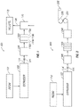
- FIG. 1 illustrates an example pelletization-based extrusion system 100 that can be used in a method to form a polyolefin product while controlling molecular weight.
- the pelletization-based extrusion system 100 may include an extruder 102, a throttle valve 104, a melt pump 106, a screen pack 108, and a pelletizer 110.
- a resin 112 may be fed to the extruder 102.
- the resin 112 may be in the form of powder, pellets, spheres, solution, or in any other form suitable for extrusion.
- the resin 112 may include polyolefin, such as polyethylene or polypropylene.
- the resin 112 may be a high density polyethylene (HDPE) used for pipe, bags, and other applications.
- the resin 112 may be a bimodal polyethylene.
- the resin 112 may be a linear low density polyethylene (LLDPE) that is used for film applications.
- HDPE high density polyethylene
- LLDPE linear low density polyethylene
- the resin 112 may be heated and softened to form a melt 114.
- the extruder 102 generally may be a device for forming the melt 114 and optionally blending additives with the melt 114. While not illustrated, the extruder 102 may have single or twin screws placed in a barrel, which can have minimal clearance between the screws and the inner surface of the barrel. Each screw may have a spiral ridge, or flights, that form openings between the barrel and the screw. The depth of the flight may be changed to change the shear and stress applied to the resin 112, with shallower flights creating a higher stress environment.
- the resin 112 may be sheared in the flights creating friction that melts or heats the resin 112 as it is forced down the barrel.
- the melt 114 may be forced out an opening at the end of the barrel into downstream equipment, such as melt pump 108.
- the extruder 102 may be a standard extruder configured to form the melt 114 from the resin 112 or may be a devolatizing extruder configured to remove solvent from a plastic in a solution to form the melt 114.
- Embodiments disclosed herein are not limited to extruders, but may also use polymer mixers, which may use counter rotating, non-intermeshed blending elements to impart shear to a resin, forming the melt 114.
- the extruder 102 may be any number of melt-processing extruders and devolatilization extruders of any design, including, for example, twin-screw extruders marketed by Coperion GMBH, of Stuttgart Germany, under the ZSK trade name and twin-rotor mixers marketed by KOBELCO, Kobe Steel Ltd. of Tokyo Japan, under the LCM trade name.
- Other extruders that may be used in the present technique include those marketed by David-Standard, LLC of Pawcatuck, Connecticut, USA, and KraussMaffei Berstorff GMBH of Hannover, Germany. It should be noted that the listed extruders are merely exemplary, as any number of single-screw or twin-screw extruders from these or other suppliers may be used.
- the throttle valve 104 may be positioned at the exit of the extruder 102.
- the throttle valve 104 may control exit of the melt 114 from the extruder 102.
- the throttle valve 104 may be closed to restrict flow of the melt 114 from the extruder 102.
- the SEI in the extruder 102 may be controlled.
- the throttle valve 104 may be partially closed to increase the SEI in the extruder 102.
- the throttle valve 104 may be set at any suitable set point, including 100%, 90%, 80%, 70%, 60%, 50%, 40%, 30%, 20%, or 10% open. While FIG. 1 illustrates use of the throttle valve 104 to control the flow of the melt 114 from the extruder 102, other suitable techniques, such as screens and the like, may be used to restrict flow of the melt to increase the SEI to the extruder 102.
- the melt 114 produced in the extruder 102 may be directed to a melt pump 106, which may force the melt 114 through a screen pack 108. Adjustment of the suction pressure of the melt pump 106 may also be used to control the SEI in the extruder 102. In some embodiments, the suction pressure of the melt pump 106 may be increased to thereby increase SEI in the extruder 102.
- the screen pack 108 may be used to remove solid contaminants, as well as gelled or cross-linked resin from the melt 114. By stretching out the polyolefin, the screen pack 108 can reduce gels and improve quality of the polyolefin. Standard screen packs typically use 0.841 mm (20-mesh) screens.
- Screens are typically characterized by their mesh size, which is typically a measure of the number of openings per square inch of the screen. As used herein, all references to screen size are based on the U.S. Sieve Series.
- Embodiments of the screen pack 108 may contain a plurality of screens 116a-116d arranged in series. To reduce gels, one or more of the screens 116a-116d may be tighter than 0.841 mm (20 mesh).
- the screen pack 108 comprises an inlet screen 116a having a size of from 0.841 mm (20 mesh) to 0.177 mm (80 mesh), one or more intermediate screens 116 b, 116 c having a size of 0.149 mm (100 mesh) or greater, and an outlet screen 116d having a size of from 0.841 mm (20 mesh) to 0.177 mm (80 mesh).
- the advantages of passing the melt 114 through a screen arrangement in the screen pack 108 include breaking up and dispersion of gels in the melt 114 resulting in a polyolefin with a reduced gel count.
- one or both of the inlet screen 116a or the outlet screen 116d may have a size of 0.841 mm (20 mesh).
- one or more of the intermediate screens 116b, 116c may have a screen size of from 0.074 mm (200 mesh) to 0.058 mm (250 mesh) and, alternative, at least one of the intermediate screens 116b, 116c may have a screen size as high as 0.037 mm (400 mesh). While FIG.
- embodiments encompass using more or less than two intermediate screens 116b, 116c in the screen pack 108.
- embodiments may include 3, 4, or even more intermediate screens 116b, 116c.
- specific embodiments may include one or more intermediate screens (not shown) having a screen size from 0.841 mm (20 mesh) to 0.177 mm (80 mesh) that is in line with the intermediate screens 116b, 116c of 0.149 mm (100 mesh) or greater. It may be desirable, in some embodiments, to stagger the screen size in the screen pack 108, for example, alternating coarse screens (e.g.
- the intermediate screens 114b, 114c may include a coarse screen (e.g., 0.841 mm (20 mesh) to 0.177 mm (80 mesh) sandwiched between fine screens (0.149 mm (100 mesh) or larger).
- screen arrangements that may be used in the screen pack include, without limitation, 0.841-0.149-0.841 mm (20-100-20), 0.841-0.058-0.149-0.841 mm (20-250-100-20), 0.841-0.037-0.149-0.841 mm (20-400-100-20), 0.841-0.149-0.841-0.149-0.841 mm (20-100-20-100-20), and 0.841-0.058-0.841-0.058-0.149-0.841 mm (20-250-20-250-100-20).
- the melt 114 can be fed to a pelletizer 110.
- Pellets 118 can be isolated from a conveying liquid 120 from the pelletizer 110.
- Pelletizers of any variety suitable configurations for pelletizing systems may be used. While pellets 118 are illustrated, other configurations of the pelletization-based extrusion system 100 may be used in the production or fabrication of alternative polyolefin products, including pipe, sheet, film, or any number of other products.
- FIG. 2 illustrates a film-based extrusion system 200 that can be used in a method to form a polyolefin product with reduced gels.
- the embodiment of FIG. 2 is similar to Fig. 1 except rather than producing pellets 118, the film-based extrusion system 200 includes components for film production.
- resin 112 may be fed to the extruder 102 where the resin 112 may be heated and softened to form the melt 114.
- Throttle valve 104 may be positioned at the exit of the extruder 102 to control flow of the melt 114 from the extruder 102.
- the throttle valve 104 or other techniques described herein may be used for adjusting the SEI in the extruder 102 for gel reduction.
- the melt 114 from the extruder may be directed to the melt pump 106 which forces the melt 114 through the screen pack 108.
- the melt 114 from the screen pack 108 may be fed to a die 202 with orifices (not shown) forming a polyolefin film which may then be passed through rolls 204, 206 to storage roll 208 whereupon the polyolefin film may be wound and stored.
- the illustrated pelletization-based extrusion system 100 shown and described with reference to FIG. 1 and the film-based extrusion system 200 shown and described with reference to FIG. 2 may be used with polyolefins from any polymerization process.
- Embodiments for producing the polyolefins disclosed herein may employ any suitable process for the polymerization of olefins, including any suspension, solution, slurry, or gas phase process, using known equipment and reaction conditions, and are not limited to any specific type of polymerization system.
- the polymerization process may be a continuous gas phase process, such as a fluid bed process.
- a fluid bed reactor for use in the process of the present invention typically has a reaction zone and a so-called velocity reduction zone (disengagement zone).
- the reaction zone includes a bed of growing polymer particles, formed polymer particles and a minor amount of catalyst particles fluidized by the continuous flow of the gaseous monomer and diluent to remove heat of polymerization through the reaction zone.
- some of the recirculated gases may be cooled and compressed to form liquids that increase the heat removal capacity of the circulating gas stream when readmitted to the reaction zone.
- a suitable rate of gas flow may be readily determined by simple experiment.
- Makeup of gaseous monomer to the circulating gas stream is at a rate equal to the rate at which particulate polymer product and monomer associated therewith is withdrawn from the reactor, and the composition of the gas passing through the reactor is adjusted to maintain an essentially steady state gaseous composition within the reaction zone.
- the gas leaving the reaction zone is passed to the velocity reduction zone where entrained particles are removed. Finer entrained particles and dust may be removed in a cyclone and/or fine filter.
- the gas is passed through a heat exchanger wherein the heat of polymerization is removed, compressed in a compressor and then returned to the reaction zone.
- Useful gas phase polymerization processes include those that utilize a fluidized bed reactor. This type of reactor, and means for operating the reactor, are well known and are described in, for example, U.S. Patent Nos. 3,709,853 ; 4,003,712 ; 4,011,382 ; 4,302,566 ; 4,543,399 ; 4,882,400 ; 5,352,749 ; 5,541,270 ; EP-A-0 802 202 . These patents disclose gas phase polymerization processes wherein the polymerization medium is either mechanically agitated or fluidized by the continuous flow of the gaseous monomer and diluent.
- the process described herein is suitable for the production of homopolymers of olefins, including ethylene, and/or copolymers, terpolymers, and the like, of olefins, including polymers comprising ethylene and at least one or more other olefins.
- the olefins may be alpha-olefins.
- the olefins for example, may contain from 2 to 16 carbon atoms in one embodiment.
- ethylene and a comonomer comprising from 3 to 12 carbon atoms, or from 4 to 10 carbon atoms, or from 4 to 8 carbon atoms, may be used.
- polyethylene may be prepared by the process disclosed herein.
- Such polyethylene may include homopolymers of ethylene and interpolymers of ethylene and at least one alpha-olefin wherein the ethylene content is at least about 50% by weight of the total monomers involved.
- Olefins that may be used herein include ethylene, propylene, 1-butene, 1-pentene, 1-hexene, 1-heptene, 1-octene, 4-methylpent-1-ene, 1-decene, 1-dodecene, 1-hexadecene and the like.
- polyenes such as 1,3-hexadiene, 1,4-hexadiene, cyclopentadiene, dicyclopentadiene, 4-vinylcyclohex-1-ene, 1,5-cyclooctadiene, 5-vinylidene-2-norbornene and 5-vinyl-2-norbomene, and olefins formed in situ in the polymerization medium.
- the content of the alpha-olefin incorporated into the copolymer may be no greater than 30 mol % in total, or may be from 3 to 20 mol %.
- polyethylene when used herein is used generically to refer to any or all of the polymers comprising ethylene described above.
- propylene-based polymers may be prepared by processes disclosed herein.
- Such propylene-based polymers may include homopolymers of propylene and interpolymers of propylene and at least one alpha-olefin wherein the propylene content is at least about 50% by weight of the total monomers involved.
- Comonomers that may be used may include ethylene, 1-butene, 1-pentene, 1-hexene, 1-heptene, 1-octene, 4-methylpentene-1, 1-decene, 1-dodecene, 1-hexadecene and the like.
- polyenes such as 1,3-hexadiene, 1,4-hexadiene, cyclopentadiene, dicyclopentadiene, 4-vinylcyclohexene-1, 1,5-cyclooctadiene, 5-vinylidene-2-norbornene and 5-vinyl-2-norbomene, and olefins formed in situ in the polymerization medium.
- the content of the alpha-olefin comonomer incorporated into a propylene-based polymer may be no greater than 49 mol % in total, from 3 to 35 mol % in other embodiments.
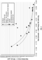
- Hydrogen gas is often used in olefin polymerization to control the final properties of the polyolefin.
- Increasing the concentration (partial pressure) of hydrogen may increase the melt flow index (I21) and/or melt index (I2) of the polyolefin generated.
- the MFI or MI can thus be influenced by the hydrogen concentration.
- the amount of hydrogen in the polymerization can be expressed as a mole ratio relative to the total polymerizable monomer, for example, ethylene, or a blend of ethylene and hexene or propylene.
- the amount of hydrogen used in the polymerization processes of the present invention may be an amount necessary to achieve the desired MFI or MI of the final polyolefin resin.
- Melt flow rate for polypropylene may be measured according to ASTM D 1238 (230°C with 2.16 kg weight); melt index (I 2 ) for polyethylene may be measured according to ASTM D 1238 (190°C with 2.16 kg weight).
- gas phase processes contemplated include series or multistage polymerization processes.
- a staged reactor employing two or more reactors in series may be used, wherein one reactor may produce, for example, a high molecular weight component and another reactor may produce a low molecular weight component.
- the polyolefin is produced using a staged gas phase reactor.
- Such polymerization systems are described in, for example, U.S. Patent Nos. 5,627,242 ; 5,665,818 ; and 5,677,375 ; and European publications EP-A-0 794 200 ; EP-B1-0 649 992 , EP-A-0 802 202 and EP-B-634 421 .
- the one or more reactors in a gas phase or fluidized bed polymerization process may have a pressure ranging from about 0.07 MPa to about 7 MPa ((about 0.7 to about 70 bar) (about 10 to about 1000 psia)), or from about 1.4 MPa to about 4.2 MPa ((about 14 to about 42 bar) (about 200 to about 600 psia)).
- the one or more reactors may have a temperature ranging from about 10°C to about 150°C, or from about 40°C to about 125°C.
- the reactor temperature may be operated at the highest feasible temperature taking into account the sintering temperature of the polymer within the reactor.
- the superficial gas velocity in the one or more reactors may range from about 0.2 to about 1.1 meters/second (about 0.7 to about 3.5 feet/second), or from about 0.3 to about 0.8 meters/second (about 1.0 to about 2.7 feet/second).
- Some embodiments of this disclosure may be especially useful with gas phase polymerization systems, at pressures in the range from 0.007 MPa to 6.89 MPa ((0.07 to 68.9 bar (1 to 1000 psig)), from 0.345 MPa to 2.76 MPa ((3.45 to 27.6 bar (50 to 400 psig)) in some embodiments, from 0.689 MPa to 2.41 MPa ((6.89 to 24.1 bar (100 to 350 psig)) in other embodiments, and temperatures in the range from 30 to 130°C, or from 65 to 110°C, from 75 to 120°C in other embodiments, or from 80 to 120°C in other embodiments. In some embodiments, operating temperatures may be less than 112°C. Stirred or fluidized bed gas phase polymerization systems may be of use in embodiments.
- the polymerization process may be a continuous gas phase process that includes the steps of: (a) introducing a recycle stream (including ethylene and alpha olefin monomers) into the reactor; (b) introducing the supported catalyst system; (c) withdrawing the recycle stream from the reactor; (d) cooling the recycle stream; (e) introducing into the reactor additional monomer(s) to replace the monomer(s) polymerized; (f) reintroducing the recycle stream or a portion thereof into the reactor; and (g) withdrawing a polymer product from the reactor.
- a recycle stream including ethylene and alpha olefin monomers
- one or more olefins, C 2 to C 30 olefins or alpha-olefins, including ethylene or propylene or combinations thereof, may be prepolymerized in the presence of a metallocene catalyst system prior to the main polymerization.
- the prepolymerization may be carried out batch-wise or continuously in gas, solution or slurry phase, including at elevated pressures.
- the prepolymerization can take place with any olefin monomer or combination and/or in the presence of any molecular weight controlling agent such as hydrogen.
- any molecular weight controlling agent such as hydrogen.
- any type of polymerization catalyst may be used, including liquid-form catalysts, solid catalysts, and heterogeneous or supported catalysts, among others, and may be fed to the reactor as a liquid, slurry (liquid/solid mixture), or as a solid (typically gas transported).
- Liquid-form catalysts useful in embodiments disclosed herein should be stable and sprayable or atomizable. These catalysts may be used alone or in various combinations or mixtures. For example, one or more liquid catalysts, one or more solid catalysts, one or more supported catalysts, or a mixture of a liquid catalyst and/or a solid or supported catalyst, or a mixture of solid and supported catalysts may be used. These catalysts may be used with co-catalysts, activators, and/or promoters well known in the art. Examples of suitable catalysts include:
- Ziegler-Natta catalyst compounds are disclosed in ZIEGLER CATALYSTS 363-386 (G. Fink, R. Mulhaupt and H. H. Brintzinger, eds., Springer-Verlag 1995 ); or in EP 103 120 ; EP 102 503 ; EP 0 231 102 ; EP 0 703 246 ; RE 33,683 ; U.S. Pat. Nos. 4,302,565 ; 5,518,973 ; 5,525,678 ; 5,288,933 ; 5,290,745 ; 5,093,415 and 6,562,905 .
- Such catalysts include those having Group 4, 5 or 6 transition metal oxides, alkoxides and halides, or oxides, alkoxides and halide compounds of titanium, zirconium or vanadium; optionally in combination with a magnesium compound, internal and/or external electron donors (alcohols, ethers, siloxanes, etc.), aluminum or boron alkyl and alkyl halides, and inorganic oxide supports.
- Conventional-type transition metal catalysts can be used.
- Conventional type transition metal catalysts include traditional Ziegler-Natta catalysts in U.S. Pat. Nos. 4,115,639 , 4,077,904 , 4,482,687 , 4,564,605 , 4,721,763 , 4,879,359 and 4,960,741 .
- Conventional-type transition metal catalysts can be represented by the formula: MR x , where M is a metal from Groups 3 to 17, or a metal from Groups 4 to 6, or a metal from Group 4, or titanium; R is a halogen or a hydrocarbyloxy group; and x is the valence of the metal M. Examples of R include alkoxy, phenoxy, bromide, chloride and fluoride.
- Preferred conventional-type transition metal catalyst compounds include transition metal compounds from Groups 3 to 17, or Groups 4 to 12, or Groups 4 to 6.
- transition metal catalyst compounds based on magnesium/titanium electron-donor complexes are described in, for example, U.S. Pat. Nos. 4,302,565 and 4,302,566 .
- Catalysts derived from Mg/Ti/Cl/THF are also contemplated, which are well known to those of ordinary skill in the art.
- Suitable chromium catalysts include di-substituted chromates, such as CrO 2 (OR) 2 ; where R is triphenylsilane or a tertiary polyalicyclic alkyl.
- the chromium catalyst system can further include CrO 3 , chromocene, silyl chromate, chromyl chloride (CrO 2 Cl 2 ), chromium-2-ethyl-hexanoate, chromium acetylacetonate (Cr(AcAc) 3 ), and the like.
- Illustrative chromium catalysts are further described in U.S. Pat. Nos. 3,231,550 ; 3,242,099 ; and 4,077,904 .
- Metallocenes are generally described throughout in, for example, 1 & 2 METALLOCENE-BASED POLYOLEFINS (John Scheirs & W. Kaminsky eds., John Wiley & Sons, Ltd. 2000 ); G. G. Hlatky in 181 COORDINATION CHEM. REV. 243-296 (1999 ) and in particular, for use in the synthesis of polyethylene in 1 METALLOCENE-BASED POLYOLEFINS 261-377 (2000 ).
- the metallocene catalyst compounds can include "half sandwich” and “full sandwich” compounds having one or more Cp ligands (cyclopentadienyl and ligands isolobal to cyclopentadienyl) bound to at least one Group 3 to Group 12 metal atom, and one or more leaving group(s) bound to the at least one metal atom.
- Cp ligands cyclopentadienyl and ligands isolobal to cyclopentadienyl
- leaving group(s) bound to the at least one metal atom.
- the Cp ligands are one or more rings or ring system(s), at least a portion of which includes ⁇ -bonded systems, such as cycloalkadienyl ligands and heterocyclic analogues.
- the ring(s) or ring system(s) typically include atoms selected from Groups 13 to 16 atoms, or the atoms that make up the Cp ligands can be selected from carbon, nitrogen, oxygen, silicon, sulfur, phosphorous, germanium, boron and aluminum and combinations thereof, wherein carbon makes up at least 50% of the ring members.
- the Cp ligand(s) can be selected from substituted and unsubstituted cyclopentadienyl ligands and ligands isolobal to cyclopentadienyl, non-limiting examples of which include cyclopentadienyl, indenyl, fluorenyl and other structures.
- Such ligands include cyclopentadienyl, cyclopentaphenanthreneyl, indenyl, benzindenyl, fluorenyl, octahydrofluorenyl, cyclooctatetraenyl, cyclopentacyclododecene, phenanthrindenyl, 3,4-benzofluorenyl, 9-phenylfluorenyl, 8-H-cyclopent[a]acenaphthylenyl, 7H-dibenzofluorenyl, indeno[1,2-9]anthrene, thiophenoindenyl, thiophenofluorenyl, hydrogenated versions thereof (e.g., 4,5,6,7-tetrahydroindenyl, or "H 4 Ind”), substituted versions thereof, and heterocyclic versions thereof.
- cyclopentadienyl cyclopentaphenanthreneyl
- the one or more metallocene catalyst components are represented by the formula (I): Cp A Cp B MX n (I)
- the metal atom "M" of the metallocene catalyst compound may be selected from the group consisting of Groups 3 through 12 atoms and lanthanide Group atoms in one embodiment; and selected from the group consisting of Groups 4, 5 and 6 atoms in yet a more particular embodiment, and a Ti, Zr, Hf atoms in yet a more particular embodiment, and Zr in yet a more particular embodiment.
- the groups bound the metal atom "M” is such that the compounds described below in the formulas and structures are neutral, unless otherwise indicated.
- the Cp ligand(s) form at least one chemical bond with the metal atom M to form the "metallocene catalyst compound".
- the Cp ligands are distinct from the leaving groups bound to the catalyst compound in that they are not highly susceptible to substitution/abstraction reactions.
- M is as described above; each X is chemically bonded to M; each Cp group is chemically bonded to M; and n is 0 or an integer from 1 to 4, and either 1 or 2 in a particular embodiment.
- the ligands represented by Cp A and Cp B in formula (I) may be the same or different cyclopentadienyl ligands or ligands isolobal to cyclopentadienyl, either or both of which may contain heteroatoms and either or both of which may be substituted by a group R.
- Cp A and Cp B are independently selected from the group consisting of cyclopentadienyl, indenyl, tetrahydroindenyl, fluorenyl, and substituted derivatives of each.
- each Cp A and Cp B of formula (I) may be unsubstituted or substituted with any one or combination of substituent groups R.
- substituent groups R as used in structure (I) include hydrogen radicals, hydrocarbyls, lower hydrocarbyls, substituted hydrocarbyls, heterohydrocarbyls, alkyls, lower alkyls, substituted alkyls, heteroalkyls, alkenyls, lower alkenyls, substituted alkenyls, heteroalkenyls, alkynyls, lower alkynyls, substituted alkynyls, heteroalkynyls, alkoxys, lower alkoxys, aryloxys, hydroxyls, alkylthios, lower alkyls thios, arylthios, thioxys, aryls, substituted aryls, heteroaryls, aralkyls, aralkylenes, alkyls, lower
- alkyl substituents R associated with formula (i) includes methyl, ethyl, propyl, butyl, pentyl, hexyl, cyclopentyl, cyclohexyl, benzyl, phenyl, methylphenyl, and tert-butylphenyl groups and the like, including all their isomers, for example tertiary-butyl, isopropyl, and the like.
- radicals include substituted alkyls and aryls such as, for example, fluoromethyl, fluroethyl, difluroethyl, iodopropyl, bromohexyl, chlorobenzyl and hydrocarbyl substituted organometalloid radicals including trimethylsilyl, trimethylgermyl, methyldiethylsilyl and the like; and halocarbyl-substituted organometalloid radicals including tris(trifluoromethyl)silyl, methylbis(difluoromethyl)silyl, bromomethyldimethylgermyl and the like; and disubstituted boron radicals including dimethylboron for example; and disubstituted Group 15 radicals including dimethylamine, dimethylphosphine, diphenylamine, methylphenylphosphine, Group 16 radicals including methoxy, ethoxy, propoxy, phenoxy, methylsulfide and
- substituents R include olefins such as but not limited to olefinically unsaturated substituents including vinylterminated ligands, for example 3-butenyl, 2-propenyl, 5-hexenyl and the like.
- at least two R groups, two adjacent R groups in one embodiment, are joined to form a ring structure having from 3 to 30 atoms selected from the group consisting of carbon, nitrogen, oxygen, phosphorous, silicon, germanium, aluminum, boron and combinations thereof.
- a substituent group R group such as 1-butanyl may form a bonding association to the element M.
- Each X in formula (I) is independently selected from the group consisting of: any leaving group in one embodiment; halogen ions, hydrides, hydrocarbyls, lower hydrocarbyls, substituted hydrocarbyls, heterohydrocarbyls, alkyls, lower alkyls, substituted alkyls, heteroalkyls, alkenyls, lower alkenyls, substituted alkenyls, heteroalkenyls, alkynyls, lower alkynyls, substituted alkynyls, heteroalkynyls, alkoxys, lower alkoxys, aryloxys, hydroxyls, alkylthios, lower alkyls thios, arylthios, thioxys, aryls, substituted aryls, heteroaryls, aralkyls, aralkylenes, alkaryls, alkarylenes, halides, haloalkyls,
- X is C 1 to C 12 alkyls, C 2 to C 12 alkenyls, C 6 to C 12 aryls, C 7 to C 20 alkylaryls, C 1 to C 12 alkoxys, C 6 to C 16 aryloxys, C 7 to C 18 alkylaryloxys, C 1 to C 12 fluoroalkyls, C 6 to C 12 fluoroaryls, and C 1 to C 12 heteroatom-containing hydrocarbons and substituted derivatives thereof in a more particular embodiment; hydride, halogen ions, C 1 to C 6 alkyls, C 2 to C 6 alkenyls, C 7 to C 18 alkylaryls, C 1 to C 6 alkoxys, C 6 to C 14 aryloxys, C 7 to C 16 alkylaryloxys, C 1 to C 6 alkylcarboxylates, C 1 to C 6 fluorinated alkylcarboxylates, C 6 to C 12 arylcarboxylates, C
- the metallocene catalyst compound and/or component may include those of formula (I) where Cp A and Cp B are bridged to each other by at least one bridging group, (A), such that the structure is represented by formula (II): Cp A (A)Cp B MX n (II) These bridged compounds represented by formula (II) are known as "bridged metallocenes.”
- Cp A , Cp B , M, X and n are as defined above for formula (I); and wherein each Cp ligand is chemically bonded to M, and (A) is chemically bonded to each Cp.
- Non-limiting examples of bridging group (A) include divalent alkyls, divalent lower alkyls, divalent substituted alkyls, divalent heteroalkyls, divalent alkenyls, divalent lower alkenyls, divalent substituted alkenyls, divalent heteroalkenyls, divalent alkynyls, divalent lower alkynyls, divalent substituted alkynyls, divalent heteroalkynyls, divalent alkoxys, divalent lower alkoxys, divalent aryloxys, divalent alkylthios, divalent lower alkyl thios, divalent arylthios, divalent aryls, divalent substituted aryls, divalent heteroaryls, divalent aralkyls, divalent aralkylenes, divalent alkaryls, divalent alkarylenes, divalent haloalkyls, divalent haloalkenyls, divalent hal
- bridging group A include divalent hydrocarbon groups containing at least one Group 13 to 16 atom, such as but not limited to at least one of a carbon, oxygen, nitrogen, silicon, aluminum, boron, germanium and tin atom and combinations thereof; wherein the heteroatom may also be C 1 to C 12 alkyl or aryl substituted to satisfy neutral valency.
- the bridging group (A) may also contain substituent groups R as defined above for formula (I) including halogen radicals and iron.
- the bridged metallocene catalyst component of formula (II) has two or more bridging groups (
- bridging group (A) include methylene, ethylene, ethylidene, propylidene, isopropylidene, diphenylmethylene, 1,2-dimethylethylene, 1,2-diphenylethylene, 1,1,2,2-tetramethylethylene, dimethylsilyl, diethylsilyl, methyl-ethylsilyl, trifluoromethylbutylsilyl, bis(trifluoromethyl)silyl, di(n-butyl)silyl, di(n-propyl)silyl, di(i-propyl)silyl, di(n-hexyl)silyl, dicyclohexylsilyl, diphenylsilyl, cyclohexylphenylsilyl, t-butylcyclohexylsilyl, di(t-butylphenyl)silyl, di(p-tolyl)silyl and the corresponding moieties
- bridging group (A) may also be cyclic, comprising, for example 4 to 10, 5 to 7 ring members in a more particular embodiment.
- the ring members may be selected from the elements mentioned above, from one or more of B, C, Si, Ge, N and O in a particular embodiment.
- Non-limiting examples of ring structures which may be present as or part of the bridging moiety are cyclobutylidene, cyclopentylidene, cyclohexylidene, cycloheptylidene, cyclooctylidene and the corresponding rings where one or two carbon atoms are replaced by at least one of Si, Ge, N and O, in particular, Si and Ge.
- the bonding arrangement between the ring and the Cp groups may be either cis-, trans-, or a combination.
- the cyclic bridging groups (A) may be saturated or unsaturated and/or carry one or more substituents and/or be fused to one or more other ring structures. If present, the one or more substituents are selected from the group consisting of hydrocarbyl (e.g., alkyl such as methyl) and halogen (e.g., F, Cl) in one embodiment.
- hydrocarbyl e.g., alkyl such as methyl
- halogen e.g., F, Cl
- the one or more Cp groups which the above cyclic bridging moieties may optionally be fused to may be saturated or unsaturated and are selected from the group consisting of those having 4 to 10, more particularly 5, 6 or 7 ring members (selected from the group consisting of C, N, O and S in a particular embodiment) such as, for example, cyclopentyl, cyclohexyl and phenyl.
- these ring structures may themselves be fused such as, for example, in the case of a naphthyl group.
- these (optionally fused) ring structures may carry one or more substituents.
- these substituents are hydrocarbyl (particularly alkyl) groups and halogen atoms.
- the ligands Cp A and Cp B of formula (I) and (II) are different from each other in one embodiment, and the same in another embodiment.
- the metallocene catalyst components include monoligand metallocene compounds (e.g., mono cyclopentadienyl catalyst components) such as described in WO 93/08221 for example.
- the at least one metallocene catalyst component is an unbridged "half sandwich" metallocene represented by the formula (III): Cp A MQ q X n (III) wherein Cp A is defined as for the Cp groups in (I) and is a ligand that is bonded to M; each Q is independently bonded to M; Q is also bound to Cp A in one embodiment; X is a leaving group as described above in (I); n ranges from 0 to 3, and is 1 or 2 in one embodiment; q ranges from 0 to 3, and is 1 or 2 in one embodiment.
- Cp A is selected from the group consisting of cyclopentadienyl, indenyl, tetrahydroindenyl, fluorenyl, substituted version thereof, and combinations thereof.
- Q is selected from the group consisting of ROO - , RO-, R(O)-, -NR-, -CR 2 -, -S-, -NR 2 , -CR 3 , -SR, -SiR 3 , -PR 2 , -H, and substituted and unsubstituted aryl groups, wherein R is selected from the group consisting of hydrocarbyls, lower hydrocarbyls, substituted hydrocarbyls, heterohydrocarbyls, alkyls, lower alkyls, substituted alkyls heteroalkyls, alkenyls, lower alkenyls, substituted alkenyls, heteroalkenyls, alkynyls, lower alkynyls, substituted alkynyls, heteroalkynyls, alkoxys, lower alkoxys, aryloxys, hydroxyls, alkylthios, lower alkyls thio
- R is selected from C 1 to C 6 alkyls, C 6 to C 12 aryls, C 1 to C 6 alkylamines, C 6 to C 12 alkylarylamines, C 1 to C 6 alkoxys, C 6 to C 12 aryloxys, and the like.
- Q include C 1 to C 12 carbamates, C 1 to C 12 carboxylates (e.g., pivalate), C 2 to C 20 allyls, and C 2 to C 20 heteroallyl moieties.
- Q 2 GZ forms a polydentate ligand unit (e.g., pivalate), wherein at least one of the Q groups form a bond with M, and is defined such that each Q is independently selected from the group consisting of -O-, -NR-, -CR 2 - and -S-; G is either carbon or silicon; and Z is selected from the group consisting of R, -OR, -NR 2 , -CR 3 , -SR, -SiR 3 , -PR 2 , and hydride, providing that when Q is -NR-, then Z is selected from the group consisting of -OR, -NR 2 , - SR, -SiR 3 , -PR 2 ; and provided that neutral valency for Q is satisfied by Z; and wherein each R is independently selected from the group consisting of hydrocarbyls, lower hydrocarbyls, substituted hydrocarbyls, heterohydrocarbyls, alkyls, lower alkyls, substitute
- R is selected from the group consisting of C 1 to C 10 heteroatom containing groups, C 1 to C 10 alkyls, C 6 to C 12 aryls, C 6 to C 12 alkylaryls, C 1 to C 10 alkoxys, and C 6 to C 12 aryloxys;
- metallocene catalysts components described above include their structural or optical or enantiomeric isomers (racemic mixture), and may be a pure enantiomer in one embodiment.
- a single, bridged, asymmetrically substituted metallocene catalyst component having a racemic and/or meso isomer does not, itself, constitute at least two different bridged, metallocene catalyst components.
- the "metallocene catalyst compound”, also referred to herein as the metallocene catalyst component” may comprise any combination of any "embodiment” described herein.
- metallocenes include but are not limited to those described in U.S. Pat. Nos. 7,179,876 , 7,169,864 , 7,157,531 , 7,129,302 , 6,995,109 , 6,958,306 , 6,884748 , 6,689,847 , 6,309,997 , 6,265,338 , U.S. Pat. App. Pub. No. 2007/0055028 , and U.S. Pat. App. Pub. No. 2006/019925 , and published PCT App. Nos.
- WO 97/22635 WO 00/699/22 , WO 01/30860 , WO 01/30861 , WO 02/46246 , WO 02/50088 , WO 04/026921 , WO 06/019494 , and WO 2010/039948 .
- a “mixed” catalyst system or “multi-catalyst” system may be used.
- a mixed catalyst system includes at least one metallocene catalyst component and at least one non-metallocene component.
- the mixed catalyst system may be described as a bimetallic catalyst composition or a multi-catalyst composition.
- the terms "bimetallic catalyst composition” and “bimetallic catalyst” include any composition, mixture, or system that includes two or more different catalyst components, each having the same or different metal group but having at least one different catalyst component, for example, a different ligand or general catalyst structure. Examples of useful bimetallic catalysts can be found in U.S. Patent Nos.
- multi-catalyst composition and “multi-catalyst” include any composition, mixture, or system that includes two or more different catalyst components regardless of the metals. Therefore, terms “bimetallic catalyst composition,” “bimetallic catalyst,” “multi-catalyst composition,” and “multi-catalyst” will be collectively referred to herein as a “mixed catalyst system” unless specifically noted otherwise.
- the described catalyst compounds may also be combined with one or more support materials or carriers.
- the activator is contacted with a support to form a supported activator wherein the activator is deposited on, contacted with, vaporized with, bonded to, or incorporated within, adsorbed or absorbed in, or on, a support or carrier.
- Support materials may include inorganic or organic support materials, such as a porous support material.
- inorganic support materials include inorganic oxides and inorganic chlorides.
- Other carriers include resinous support materials such as polystyrene, functionalized or crosslinked organic supports, such as polystyrene divinyl benzene, polyolefins or polymeric compounds, or any other organic or inorganic support material and the like, or mixtures thereof.
- the support materials may include inorganic oxides including Group 2, 3, 4, 5, 13 or 14 metal oxides, such as silica, fumed silica, alumina, silica-alumina and mixtures thereof.
- Other useful supports include magnesia, titania, zirconia, magnesium chloride, montmorillonite, phyllosilicate, zeolites, talc, clays, and the like.
- combinations of these support materials may be used, for example, silica-chromium, silica-alumina, silica-titania and the like.
- Additional support materials may include those porous acrylic polymers described in EP 0 767 184 .
- support materials include nanocomposites, as described in PCT WO 99/47598 , aerogels, as described in WO 99/48605 , spherulites, as described in U.S. Patent No. 5,972,510 , and polymeric beads, as described in WO 99/50311 .
- Support material such as inorganic oxides, may have a surface area in the range from about 10 to about 700 m 2 /g, a pore volume in the range from about 0.1 to about 4 cc/g, and an average particle size in the range from about 0.1 to about 1000 ⁇ m.
- the surface area of the support may be in the range from about 50 to about 500 m 2 /g
- the pore volume is from about 0.5 to about 3.5 cc/g
- the average particle size is from about 1 to about 500 ⁇ m.
- the surface area of the support is in the range from about 100 to about 1000 m 2 /g
- the pore volume is from about 0.8 to about 5.0 cc/g
- the average particle size is from about 1 to about 100 ⁇ m, or from about 1 to about 60 ⁇ m.
- the average pore size of the support material may be in the range from 1 nm to 100 nm (10 to 1000 ⁇ ); or from about 5 nm to about 50 nm (50 to about 500 ⁇ ); or from about 7.5 nm to about 45 nm (about 75 to about 450 ⁇ ).
- the support material is chemically treated and/or dehydrated prior to combining with the catalyst compound, activator and/or catalyst system.
- the support material may have various levels of dehydration, such as may be achieved by drying the support material at temperatures in the range from about 100°C to about 1000°C.
- dehydrated silica may be contacted with an organoaluminum or alumoxane compound.
- the activator is formed in situ in the support material as a result of the reaction of, for example, trimethylaluminum and water.
- the supported activator is formed by preparing, in an agitated, temperature and pressure controlled vessel, a solution of the activator and a suitable solvent, then adding the support material at temperatures from 0°C to 100°C, contacting the support with the activator solution, then using a combination of heat and pressure to remove the solvent to produce a free flowing powder. Temperatures can range from 40 to 120°C and pressures from 34.5 to 138 kPa (5 psia to 20 psia) . An inert gas sweep can also be used in assist in removing solvent. Alternate orders of addition, such as slurrying the support material in an appropriate solvent then adding the activator, can be used.
- the weight percent of the activator to the support material is in the range from about 10 weight percent to about 70 weight percent, or in the range from about 15 weight percent to about 60 weight percent, or in the range from about 20 weight percent to about 50 weight percent, or in the range from about 20 weight percent to about 40 weight percent.
- Conventional supported catalysts system useful in embodiments disclosed herein include those supported catalyst systems that are formed by contacting a support material, an activator and a catalyst compound in various ways under a variety of conditions outside of a catalyst feeder apparatus. Examples of conventional methods of supporting metallocene catalyst systems are described in U.S. Patent Nos.
- the catalyst components for example a catalyst compound, activator and support, may be fed into the polymerization reactor as a mineral oil slurry. Solids concentrations in oil may range from about 1 to about 50 weight percent, or from about 10 to about 25 weight percent.
- the catalyst compounds, activators and or optional supports used herein may also be spray dried separately or together prior to being injected into the reactor.
- the spray dried catalyst may be used as a powder or solid or may be placed in a diluent and slurried into the reactor. In other embodiments, the catalyst compounds and activators used herein are not supported.
- Processes disclosed herein may optionally use inert particulate materials as fluidization aids.
- These inert particulate materials can include carbon black, silica, talc, and clays, as well as inert polymeric materials.
- Carbon black for example, has a primary particle size of about 10 to about 100 nanometers, an average size of aggregate of about 0.1 to about 30 ⁇ m (microns), and a specific surface area from about 30 to about 1500 m 2 /g.
- Silica has a primary particle size of about 5 to about 50 nanometers, an average size of aggregate of about 0.1 to about 30 ⁇ m (microns), and a specific surface area from about 50 to about 500 m 2 /g.
- Clay, talc, and polymeric materials have an average particle size of about 0.01 to about 10 ⁇ m (microns) and a specific surface area of about 3 to 30 m 2 /g.
- These inert particulate materials may be used in amounts ranging from about 0.3 to about 80%, or from about 5 to about 50%, based on the weight of the final product. They are especially useful for the polymerization of sticky polymers as disclosed in U.S. Patent Nos. 4,994,534 and 5,304,588 .
- Chain transfer agents may be, and often are, used in the polymerization processes disclosed herein. Chain transfer agents are often used to control polymer molecular weight. Examples of these compounds are hydrogen and metal alkyls of the general formula M x R y , where M is a Group 3-12 metal, x is the oxidation state of the metal, typically 1, 2, 3, 4, 5 or 6, each R is independently an alkyl or aryl, and y is 0, 1, 2, 3, 4, 5, or 6. In some embodiments, a zinc alkyl is used, such as diethyl zinc.
- Typical promoters may include halogenated hydrocarbons such as CHCl 3 , CFCl 3 , CH 3 -CCl 3 , CF 2 Cl-CCl 3 , and ethyltrichloroacetate. Such promoters are well known to those skilled in the art and are disclosed in, for example, U.S. Patent No. 4,988,783 .
- Other organometallic compounds such as scavenging agents for poisons may also be used to increase catalyst activity. Examples of these compounds include metal alkyls, such as aluminum alkyls, for example, triisobutylaluminum.
- Some compounds may be used to neutralize static in the fluidized-bed reactor, others known as drivers rather than antistatic agents, may consistently force the static from positive to negative or from negative to positive.
- the use of these additives is well within the skill of those skilled in the art. These additives may be added to the circulation loops, riser, and/or downer separately or independently from the liquid catalyst if they are solids, or as part of the catalyst provided they do not interfere with the desired atomization. To be part of the catalyst solution, the additives should be liquids or capable of being dissolved in the catalyst solution.
- the gas phase process may be operated in the presence of a metallocene-type catalyst system and in the absence of, or essentially free of, any scavengers, such as triethylaluminum, trimethylaluminum, triisobutylaluminum and tri-n-hexylaluminum and diethyl aluminum chloride, dibutyl zinc, and the like.
- any scavengers such as triethylaluminum, trimethylaluminum, triisobutylaluminum and tri-n-hexylaluminum and diethyl aluminum chloride, dibutyl zinc, and the like.
- essentially free it is meant that these compounds are not deliberately added to the reactor or any reactor components, and if present, are present in the reactor at less than 1 ppm.
- the reactors disclosed herein are capable of producing greater than 227 kg of polymer per hour (500 lbs of polymer per hour) to about 136,000 kg/hr (300,000 lbs/hr) or higher of polymer, preferably greater than 455 kg/hr (1000 lbs/hr), more preferably greater than 4540 kg/hr (10,000 lbs/hr), even more preferably greater than 11,300 kg/hr (25,000 lbs/hr), still more preferably greater than 15,900 kg/hr (35,000 lbs/hr), still even more preferably greater than 22,700 kg/hr (50,000 lbs/hr) and most preferably greater than 29,000 kg/hr (65,000 lbs/hr) to greater than 68,100 kg/hr (150,000 lbs/hr).
- the polymers produced by the processes described herein can be used in a wide variety of products and end-use applications.
- the polymers produced may include linear low density polyethylene, elastomers, plastomers, high density polyethylene, medium density polyethylene, low density polyethylene, polypropylene homopolymers and polypropylene copolymers, including random copolymers and impact copolymers.
- the polymers typically ethylene-based polymers, have a density, for example, in the range of from 0.86 g/cc to 0.97 g/cc, in another embodiment, in the range of from 0.88 g/cc to 0.965 g/cc, and, in yet another embodiment, in the range of from 0.900 g/cc to 0.96 g/cc.
- propylene-based polymers are produced. These polymers include atactic polypropylene, isotactic polypropylene, hemi-isotactic and syndiotactic polypropylene. Other propylene polymers include propylene block, random, or impact copolymers. Propylene polymers of these types are well known in the art, see for example U.S. Patent Nos. 4,794,096 , 3,248,455 , 4,376,851 , 5,036,034 and 5,459,117 .
- the polymers may be blended and/or coextruded with any other polymer.
- Non-limiting examples of other polymers include linear low density polyethylene produced via conventional Ziegler-Natta and/or bulky ligand metallocene catalysis, elastomers, plastomers, high pressure low density polyethylene, high density polyethylene, polypropylene, and the like.
- Polymers produced by the processes disclosed herein and blends thereof are useful in such forming operations as film, sheet, and fiber extrusion and co-extrusion as well as blow molding, injection molding and rotary molding.
- Films include blown or cast films formed by co-extrusion or by lamination useful as shrink film, cling film, stretch film, sealing films, oriented films, snack packaging, heavy duty bags, grocery sacks, baked and frozen food packaging, medical packaging, industrial liners, membranes, etc. in food-contact and non-food contact applications.
- Polymerization processes disclosed herein may also be operated in a condensing mode, similar to those disclosed in U.S. Patent Nos. 4,543,399 , 4,588,790 , 4,994,534 , 5,352,749 , 5,462,999 , and 6,489,408 , and U.S. Patent Appl. Pub. No. 2005/0137364 .
- Condensing mode processes may be used to achieve higher cooling capacities and, hence, higher reactor productivity.
- other condensable fluids inert to the polymerization may be introduced to induce a condensing mode operation, such as by the processes described in U.S. Patent No. 5,436,304 .
- Polyolefins of particular embodiments may have a density from about 0.910 g/cm 3 to about 0.975 g/cm 3 , from about 0.930 g/cm 3 to about 0.965 g/cm 3 , from about 0.935 g/cm 3 to about 0.965 g/cm 3 , from about 0.950 g/cm 3 to about 0.958 g/cm 3 , or from about 0.952 g/cm 3 to about 0.954 g/cm 3
- Polyolefins of particular embodiments may have melt indices (I 2 ) ranging from about 0.1 g/10 min to about 1000 g/10 min.
- the polymers may have flow indices (I 21 ) ranging from about 0.3 g/10 min to about 300 g/10 min.
- the polymers may have flow indices (I 21 ) ranging from about 0.5 g/10 min to about 50 g/10 min, from about 1 g/10 min to about 20 g/10 min, or from about 2 g/10 min to about 12 g/10 min, or from about 2.5 g/10 min to about 5 g/10 min.
- Polyolefins of particular embodiments may have a melt index ratio (I 21 /I 2 ) of from 14 to 60 in one embodiment, from 14 to 34 in another embodiment, from 15 to 30 in another embodiment, from 15 to 28 in yet another embodiment, or from 15 to 25 in yet another embodiment.
- I 21 /I 2 melt index ratio
- Polyolefins of particular embodiments may have a melt strength at yield of greater than about 1 cN in one embodiment, greater than about 2.0 cN in another embodiment, greater than about 2.5 cN in yet another embodiment, greater than about 3.0 cN in another embodiment, and greater than about 3.5 cN in yet another embodiment.
- test methods should be utilized to obtain the numerical values for certain properties and features as set forth in the claims, e.g. density, flow indices or melt indices, although it is understood that those values also refer to any results obtained by other testing or measuring methods that might not necessarily be disclosed herein, provided such other testing or measuring methods are published, e.g., in at least one patent, patent application, or scientific publication.
- Density values are based on ASTM D-792.
- Flow Index (I 21 ) values are based on ASTM D1238, run at 190°C, with 21.6 kg weight; the standard designation for that measurement is 190/21.60.
- Melt Strength (MS) values are based on the polymer yield point in the melt strength curve generated with the Rheotens instrument with a starting velocity of 9.8 mm/sec and a velocity at yield in the range of about 32 to 33 mm/sec.
- M w /M n Molecular weight distribution (M w /M n ) was determined using Size Exclusion Chromatography, which was measured using Polymer Laboratories instrument; Model: HT-GPC-220, Columns: Shodex, Run Temp: 140° C., Calibration Standard: traceable to NIST, Solvent: 1,2,4-Trichlorobenzene.
- BBF Butyl branching frequency as measured by 13 C-NMR. The value is the number of butyl branches per 1000 carbon atoms.
- Comparative testing was performed with a Coperion GMBH ZSK-70 mm co-rotating twin screw extruder with Gear Pump ZP-90, Screen Pack Changer SWZ-300 and Pelletizer Unit UG-122 to evaluate the effect of SEI on gel reduction.
- the ZSK extruder comprised of five individually temperature controlled barrels. The first barrel in the arrangement was used as the feed barrel with no heat applied to it.
- the screw design uses a first mixing and melting section followed by distributive section and finally a melt homogenization section. The produced pellets were employed to make a film and the gel count of the film was determined.
- Polyethylene pellets produced were extruded into a film without any additives.
- the polyethylene pellets were Metallocene Resins having a density from 0.9135 to 0.9185 g/cm 3 , an I 2 value of from 0.30 to 0.60 dg/min, and I 21 /I 2 value of from 25 to 35, produced in a commercial-scale gas phase UNIPOL reactor system.
- the quantity of gels for the resultant film was determined using an Optical Control Systems (OCS) gel counting apparatus.
- OCS Optical Control Systems
- the OCS extrusion machine converts the pellets into cast film and uses an advanced camera system to detect optical defects, including gels, in the film. Settings are adjusted to count defects within specific ranges of size. The smallest defect typically detected is about 50 ⁇ m (microns) in diameter size.
- Table 2 shows the specification of gel counts by size. Total gel count indicates the total number of gels larger than 50 ⁇ m. The "> 200 ⁇ m" count indicates the total number of gels that are larger than 200 ⁇ m in size.
- Total defect area (TDA) is a measure of the concentration of gels in the film based on the gel count, gel size, and total film area assessed.
- the total defect area indicates the area of gels divided by the area of film and is reported in parts per million (ppm).
- the TDA is reported along with the basis for the measurement.
- Table 2 indicates TDA100, which is the total defect area including gels larger than 100 qm in size.
- Table 2 also includes some data for TDA200, which is the total defect area for gels larger than 200 qm in size.
- Table 1 below shows the different extrusion conditions.
- Table 2 below shows the TDA and gel counts values for the different extrusion conditions.
- Samples 1 to 20 compare different screen pack arrangements with constant screw speed. In particular, Samples 1 to 20 compare gel reduction for no screen, a 0.841 mm (20-mesh) screen, a 0.149 mm (100 mesh) Dutch Weave screen, a 0.841/0.149/0.841/0.149 mm (20/100/24/100 mesh) stacked screen pack, 0.841/0.149/0.841/0.149 mm (20/100DW/20/100DW mesh) stacked screen pack, and a 0.841/0.120/0.707/0.120 mm (20/125/25/125 mesh) stacked screen pack.
- samples 11 and 22 to 24 compare adjusting gel counts for specific energy input by increasing screw speed. In particular, samples 11 and 22 to 24 increased screw speed from 270 rotations per minute ("RPM") to 570 RPM with 100% throttle valve open. Sample 25 used the throttle valve to increase SEI. In particular, the throttle valve was 87% closed for Sample 25 at a screw speed of 570 RPM as compared to Sample 24 which had the throttle valve 100% open at a screw speed of 570 RPM.
- FIG. 1 shows the total defect area results as a function of SEI for Samples 1 to 25.
- compositions, methods, and processes are described herein in terms of “comprising,” “containing,” “having,” or “including” various components or steps, the compositions and methods can also “consist essentially of” or “consist of” the various components and steps.
- the phrases, unless otherwise specified, “consists essentially of” and “consisting essentially of” do not exclude the presence of other steps, elements, or materials, whether or not, specifically mentioned in this specification, so long as such steps, elements, or materials, do not affect the basic and novel characteristics of the invention, additionally, they do not exclude impurities and variances normally associated with the elements and materials used.
- the singular forms “a,” “an” and “the” include plural referents unless otherwise specified.
- ranges from any lower limit may be combined with any upper limit to recite a range not explicitly recited, as well as, ranges from any lower limit may be combined with any other lower limit to recite a range not explicitly recited; in the same way, ranges from any upper limit may be combined with any other upper limit to recite a range not explicitly recited.
Description
- This disclosure generally relates to gel reduction in polyolefins. In particular, this disclosure relates to methods for extrusion of polyolefins that control specific energy input to the extruder for gel reduction.
-
EP-A-2,256,160 relates to a polyethylene composition comprising 1) contacting, in a first gas phase fluidized bed reactor, a gaseous composition, a supported titanium magnesium catalyst precursor and co-catalyst. The HMW polymer produced is transferred to a second gas phase fluidized bed reactor together with a further gaseous composition. The resulting polymer blend product is then melted in an extruder and then passed through one or more active screens, wherein in the case of two or more active screens, the screens are positioned in series, each active screen having a micron retention size of from about 2 to about 70, at a mass flux of about 5 to about 100 lb/hr/in2 (1.0 to 20 kg/s/m2) to form a screened molten polymer blend. -
US-A-2007/100132 relates to a process of producing a polyolefin, the process comprising providing a polyolefin having an I21 value of from 2 to 100 g/10 min and a density of from 0.91 to 0.97 g/cm3 ; followed by forming a melt of the polyolefin and passing the polyolefin through one or more active screen filter(s) having a mesh size of from 70 to 200 micron at a mass flux of from 5 to 100 lbs/hr/square inch; and isolating the polyolefin having passed through the screen filter. -
US-A-2012/214931 relates to a process for the production of a polymer composite, in which at least one solid or solids mixture and one or more thermoplastic polymers are mixed in a co-rotating, tightly meshing screw extruder and then extruded, characterised in that the screw extruder has a ratio of the melt-wetted length L melt to the barrel inside diameter D of the screw extruder in the range from L melt/D=4 to L melt/D=19, and the standardised volumetric throughput Q/(N*D 3) is in the range from 0.08 1/s to 1.0 1/s, wherein Q is the volumetric throughput and N is the number of screw shafts. -
US-A-2012/205832 relates to a process for producing a homogeneous polyolefin composition comprising the steps of: (a) providing one or more high molecular weight olefin polymer components and one or more low molecular weight polyolefin components; (b) compounding the high molecular weight olefin polymer component and the low molecular weight polyolefin component in a mixer comprised of two or more dissimilar rotors offset to one another at the apex to create a homogeneous multimodal polyolefin melt; (c) moving the melt from the mixer into an extruder; and (d) pressurizing the melt to move it from the extruder through a pelletizing die plate, wherein the polymer flow is divided into separate streams and cut into homogeneous multimodal polyolefin composition pellets. -
EP-A-1,600,276 relates to the use of a counter-rotating twin screw extruder for compounding multimodal polymer compositions wherein the screw extruder has a body forming a chamber of two barrels housing two counter-rotating axis-parallel rotors, a supply port for the material to be mixed in the chamber at one end of the body, a discharge port for discharging the mixed material at the other end of the body, a conveying section with screws for feeding the material from the supply port downstream to a mixing section which comprises at least two mixing zones, each mixing zone having at least one forwardconveying wing and at least one backward-conveying wing downstream of the forwardconveying wing on each rotor. - Films extruded from high density polyolefins, especially high density polyethylene, have become an important product worldwide. Even more particularly, the use of multimodal or bimodal polyethylene in films has gained market share over traditional unimodal polyethylene. In order to make such films, complex reaction processes such as the use of multi-site catalysts and/or multi-stage reactors are necessary. This can often lead to problems in the quality of the film, such as the presence of gels. Gels are highly localized imperfections in the film that are visually distinct from the surrounding film. There are typically several different causes of gels, including unblended polymer, unreacted catalyst and activator, localized areas of varying molecular weight, localized areas of crosslinked material, and contamination (e.g., inorganics, sand, carbon black, etc.) that can reflect and transmit light differently from the surrounding polymer. The presence of gels can lower the value of these films and, in some cases, makes the films unmarketable.
- A number of different techniques may be used to reduce gel formation in polyolefins. Careful control of upstream systems and extrusion temperatures can prevent contaminants such as fibers and degraded polymer or black specks that cause gels. While these techniques may be suitable for reducing certain types of gels, improved techniques for reduction of gels in polyolefins are needed, especially those techniques that can reduce gels due to localized areas of varying molecular weight which can be hard to remove.
- Disclosed herein is an example method for forming plastic products (120, 208) with reduced gels, comprising:
- melting a polyolefin resin (112) in extruder (102) to form a melt (114);
- adjusting specific energy input in the extruder (102) to reduce gels in the melt (114);
- forming the melt (114) into a polyolefin product (120, 208), and passing the melt (114) through a screen pack (108), wherein the screen pack (108) comprises an inlet screen (116a) having a size from 0.841 mm (20 mesh) to 0.177 mm (80 mesh), one or more intermediate screens (116b, 116c) having a size of 0.149 mm (100 mesh) or greater, and an outlet screen (116d) having a size from 0.841 mm (20 mesh) to 0.177 mm (80 mesh), wherein the one or more intermediate screens (116b, 116c) comprise a screen having a size from 0.841 mm (20 mesh) to 0.177 mm (80 mesh) sandwiched between screens of 0.149 mm (100 mesh) or larger, wherein each screen having the size from 0.841 mm (20 mesh) to 0.177 mm (80 mesh) is separated by one or more screens having the size of 0.149 mm (100 mesh) or greater.
- Disclosed herein is an example method for forming plastic products (120, 208) with reduced gels, comprising:
- melting a polyolefin resin (112) in extruder (102) to form a melt (114);
- selecting a throttle valve (104) position for gel reduction;
- setting the throttle valve (104) at the selected throttle valve (104) position to restrict flow of the melt (114) out of the extruder (102); and
- forming the melt (114) into a polyolefin product (120, 208), and passing the melt (114) through a screen pack (108), wherein the screen pack (108) comprises an inlet screen (116a) having a size from 0.841 mm (20 mesh) to 0.177 mm (80 mesh), one or more intermediate screens (116b, 116c) having a size of 0.149 mm (100 mesh) or greater, and an outlet screen (116d) having a size from 0.841 mm (20 mesh) to 0.177 mm (80 mesh), wherein the one or more intermediate screens (116b, 116c) comprise a screen having a size from 0.841 mm (20 mesh) to 0.177 mm (80 mesh) sandwiched between screens of 0.149 mm (100 mesh) or larger, wherein each screen having the size from 0.841 mm (20 mesh) to 0.177 mm (80 mesh) is separated by one or more screens having the size of 0.149 mm (100 mesh) or greater.
- For a detailed description of the preferred embodiments of the invention, reference will now be made to the accompanying drawings in which:
-
FIG. 1 is a schematic diagram of an example extrusion system that can be used in a method to form a polyolefin product; and -
FIG. 2 is a schematic diagram of another example extrusion system that can be used in a method to form a polyolefin product. -
FIG. 3 is a graphical representation showing gel reduction as a function of specific energy input in an extruder for an example extrusion process. - Before the present compounds, components, compositions, devices, equipment, configurations, schematics, systems, and/or methods are disclosed and described, it is to be understood that unless otherwise indicated this invention is not limited to specific compounds, components, compositions, devices, equipment, configurations, schematics, systems, methods, or the like, as such may vary, unless otherwise specified. It is also to be understood that the terminology used herein is for the purpose of describing particular embodiments only and is not intended to be limiting.
- This disclosure generally relates to gel reduction in polyolefins. In particular, this disclosure relates to processes and systems for extrusion of polyolefins that utilize specific energy input in the extruder to reduce gels. One example technique for adjusting specific energy input may utilize a throttle valve to adjust the specific energy input. An embodiment may include a throttle valve that may be positioned at the end of the extruder for controlling flow out of the extruder. The throttle valve may be controlled to adjust the specific energy input in the extruder. Specific energy input or "SEI" refers to the energy input of the extruder, per unit weight of melt processed resin, and is typically expressed in units of kW-hr/kg or hp-hr/lb. This can be calculated based on the energy input from the main drive of the extruder or as a total energy input that also includes the contribution of a melt pump. The throttle valve may be used to selectively restrict flow out of the extruder, which should increase the SEI and reduce gels. Additional techniques may be used to adjust SEI in the extruder, including, without limitation, increasing suction pressure on the melt pump and place other flow restrictions at the extruder outlet, such as screens and the like. Screen packs positioned after the extruder may also be used for gel reduction. Advantageously, passing the melted polyolefin through the screen pack should break up and disperse gels in the melted polyolefin, resulting in polyolefin products with a reduced gel count.
-
FIG. 1 illustrates an example pelletization-basedextrusion system 100 that can be used in a method to form a polyolefin product while controlling molecular weight. The pelletization-basedextrusion system 100 may include anextruder 102, athrottle valve 104, amelt pump 106, ascreen pack 108, and apelletizer 110. In theextrusion system 100, aresin 112 may be fed to theextruder 102. Theresin 112 may be in the form of powder, pellets, spheres, solution, or in any other form suitable for extrusion. Theresin 112 may include polyolefin, such as polyethylene or polypropylene. For example, in one embodiment, theresin 112 may be a high density polyethylene (HDPE) used for pipe, bags, and other applications. In some embodiments, theresin 112 may be a bimodal polyethylene. In other embodiments, theresin 112 may be a linear low density polyethylene (LLDPE) that is used for film applications. - In the
extruder 102, theresin 112 may be heated and softened to form amelt 114. Theextruder 102 generally may be a device for forming themelt 114 and optionally blending additives with themelt 114. While not illustrated, theextruder 102 may have single or twin screws placed in a barrel, which can have minimal clearance between the screws and the inner surface of the barrel. Each screw may have a spiral ridge, or flights, that form openings between the barrel and the screw. The depth of the flight may be changed to change the shear and stress applied to theresin 112, with shallower flights creating a higher stress environment. As the shaft of the screws is turned, theresin 112 may be sheared in the flights creating friction that melts or heats theresin 112 as it is forced down the barrel. Themelt 114 may be forced out an opening at the end of the barrel into downstream equipment, such asmelt pump 108. Theextruder 102 may be a standard extruder configured to form themelt 114 from theresin 112 or may be a devolatizing extruder configured to remove solvent from a plastic in a solution to form themelt 114. Embodiments disclosed herein are not limited to extruders, but may also use polymer mixers, which may use counter rotating, non-intermeshed blending elements to impart shear to a resin, forming themelt 114. - The
extruder 102 may be any number of melt-processing extruders and devolatilization extruders of any design, including, for example, twin-screw extruders marketed by Coperion GMBH, of Stuttgart Germany, under the ZSK trade name and twin-rotor mixers marketed by KOBELCO, Kobe Steel Ltd. of Tokyo Japan, under the LCM trade name. Other extruders that may be used in the present technique include those marketed by David-Standard, LLC of Pawcatuck, Connecticut, USA, and KraussMaffei Berstorff GMBH of Hannover, Germany. It should be noted that the listed extruders are merely exemplary, as any number of single-screw or twin-screw extruders from these or other suppliers may be used. - As illustrated, the
throttle valve 104 may be positioned at the exit of theextruder 102. Thethrottle valve 104 may control exit of themelt 114 from theextruder 102. For example, thethrottle valve 104 may be closed to restrict flow of themelt 114 from theextruder 102. By adjusting thethrottle valve 104 to control exit of themelt 114, the SEI in theextruder 102 may be controlled. For example, thethrottle valve 104 may be partially closed to increase the SEI in theextruder 102. By control of the SEI in theextruder 102 with thethrottle valve 104, gels in the polyolefin may be reduced. Thethrottle valve 104 may be set at any suitable set point, including 100%, 90%, 80%, 70%, 60%, 50%, 40%, 30%, 20%, or 10% open. WhileFIG. 1 illustrates use of thethrottle valve 104 to control the flow of themelt 114 from theextruder 102, other suitable techniques, such as screens and the like, may be used to restrict flow of the melt to increase the SEI to theextruder 102. - The
melt 114 produced in theextruder 102 may be directed to amelt pump 106, which may force themelt 114 through ascreen pack 108. Adjustment of the suction pressure of themelt pump 106 may also be used to control the SEI in theextruder 102. In some embodiments, the suction pressure of themelt pump 106 may be increased to thereby increase SEI in theextruder 102. Thescreen pack 108 may be used to remove solid contaminants, as well as gelled or cross-linked resin from themelt 114. By stretching out the polyolefin, thescreen pack 108 can reduce gels and improve quality of the polyolefin. Standard screen packs typically use 0.841 mm (20-mesh) screens. To avoid undesired pressure drops across the screen pack, the use of tighter screens has typically been avoided. Screens are typically characterized by their mesh size, which is typically a measure of the number of openings per square inch of the screen. As used herein, all references to screen size are based on the U.S. Sieve Series. - Embodiments of the
screen pack 108 may contain a plurality of screens 116a-116d arranged in series. To reduce gels, one or more of the screens 116a-116d may be tighter than 0.841 mm (20 mesh). Thescreen pack 108 comprises an inlet screen 116a having a size of from 0.841 mm (20 mesh) to 0.177 mm (80 mesh), one or moreintermediate screens 116b, 116c having a size of 0.149 mm (100 mesh) or greater, and anoutlet screen 116d having a size of from 0.841 mm (20 mesh) to 0.177 mm (80 mesh). The advantages of passing themelt 114 through a screen arrangement in thescreen pack 108 include breaking up and dispersion of gels in themelt 114 resulting in a polyolefin with a reduced gel count. In some embodiments, one or both of the inlet screen 116a or theoutlet screen 116d may have a size of 0.841 mm (20 mesh). In some embodiments, one or more of theintermediate screens 116b, 116c may have a screen size of from 0.074 mm (200 mesh) to 0.058 mm (250 mesh) and, alternative, at least one of theintermediate screens 116b, 116c may have a screen size as high as 0.037 mm (400 mesh). WhileFIG. 1 illustrates thescreen pack 108 as having twointermediate screens 116b, 116c, it should be understood that embodiments encompass using more or less than twointermediate screens 116b, 116c in thescreen pack 108. For example, embodiments may include 3, 4, or even moreintermediate screens 116b, 116c. In addition, specific embodiments may include one or more intermediate screens (not shown) having a screen size from 0.841 mm (20 mesh) to 0.177 mm (80 mesh) that is in line with theintermediate screens 116b, 116c of 0.149 mm (100 mesh) or greater. It may be desirable, in some embodiments, to stagger the screen size in thescreen pack 108, for example, alternating coarse screens (e.g. 0.841 mm (20 mesh) to 0.177 mm (80 mesh) and fine screens 0.149 mm (100 mesh) or larger). For example, the intermediate screens 114b, 114c may include a coarse screen (e.g., 0.841 mm (20 mesh) to 0.177 mm (80 mesh) sandwiched between fine screens (0.149 mm (100 mesh) or larger). Specific examples of screen arrangements that may be used in the screen pack include, without limitation, 0.841-0.149-0.841 mm (20-100-20), 0.841-0.058-0.149-0.841 mm (20-250-100-20), 0.841-0.037-0.149-0.841 mm (20-400-100-20), 0.841-0.149-0.841-0.149-0.841 mm (20-100-20-100-20), and 0.841-0.058-0.841-0.058-0.149-0.841 mm (20-250-20-250-100-20). - From the
screen pack 108, themelt 114 can be fed to apelletizer 110.Pellets 118 can be isolated from a conveying liquid 120 from thepelletizer 110. Pelletizers of any variety suitable configurations for pelletizing systems may be used. Whilepellets 118 are illustrated, other configurations of the pelletization-basedextrusion system 100 may be used in the production or fabrication of alternative polyolefin products, including pipe, sheet, film, or any number of other products. -
FIG. 2 illustrates a film-basedextrusion system 200 that can be used in a method to form a polyolefin product with reduced gels. The embodiment ofFIG. 2 is similar toFig. 1 except rather than producingpellets 118, the film-basedextrusion system 200 includes components for film production. As illustrated,resin 112 may be fed to theextruder 102 where theresin 112 may be heated and softened to form themelt 114.Throttle valve 104 may be positioned at the exit of theextruder 102 to control flow of themelt 114 from theextruder 102. Thethrottle valve 104 or other techniques described herein may be used for adjusting the SEI in theextruder 102 for gel reduction. Themelt 114 from the extruder may be directed to themelt pump 106 which forces themelt 114 through thescreen pack 108. Themelt 114 from thescreen pack 108 may be fed to a die 202 with orifices (not shown) forming a polyolefin film which may then be passed throughrolls 204, 206 tostorage roll 208 whereupon the polyolefin film may be wound and stored. - The illustrated pelletization-based
extrusion system 100 shown and described with reference toFIG. 1 and the film-basedextrusion system 200 shown and described with reference toFIG. 2 may be used with polyolefins from any polymerization process. Embodiments for producing the polyolefins disclosed herein may employ any suitable process for the polymerization of olefins, including any suspension, solution, slurry, or gas phase process, using known equipment and reaction conditions, and are not limited to any specific type of polymerization system. - In general, the polymerization process may be a continuous gas phase process, such as a fluid bed process. A fluid bed reactor for use in the process of the present invention typically has a reaction zone and a so-called velocity reduction zone (disengagement zone). The reaction zone includes a bed of growing polymer particles, formed polymer particles and a minor amount of catalyst particles fluidized by the continuous flow of the gaseous monomer and diluent to remove heat of polymerization through the reaction zone. Optionally, some of the recirculated gases may be cooled and compressed to form liquids that increase the heat removal capacity of the circulating gas stream when readmitted to the reaction zone. A suitable rate of gas flow may be readily determined by simple experiment. Makeup of gaseous monomer to the circulating gas stream is at a rate equal to the rate at which particulate polymer product and monomer associated therewith is withdrawn from the reactor, and the composition of the gas passing through the reactor is adjusted to maintain an essentially steady state gaseous composition within the reaction zone. The gas leaving the reaction zone is passed to the velocity reduction zone where entrained particles are removed. Finer entrained particles and dust may be removed in a cyclone and/or fine filter. The gas is passed through a heat exchanger wherein the heat of polymerization is removed, compressed in a compressor and then returned to the reaction zone.
- Useful gas phase polymerization processes include those that utilize a fluidized bed reactor. This type of reactor, and means for operating the reactor, are well known and are described in, for example,
U.S. Patent Nos. 3,709,853 ;4,003,712 ;4,011,382 ;4,302,566 ;4,543,399 ;4,882,400 ;5,352,749 ;5,541,270 ;EP-A-0 802 202 . These patents disclose gas phase polymerization processes wherein the polymerization medium is either mechanically agitated or fluidized by the continuous flow of the gaseous monomer and diluent. - The process described herein is suitable for the production of homopolymers of olefins, including ethylene, and/or copolymers, terpolymers, and the like, of olefins, including polymers comprising ethylene and at least one or more other olefins. The olefins may be alpha-olefins. The olefins, for example, may contain from 2 to 16 carbon atoms in one embodiment. In other embodiments, ethylene and a comonomer comprising from 3 to 12 carbon atoms, or from 4 to 10 carbon atoms, or from 4 to 8 carbon atoms, may be used.
- In embodiments, polyethylene may be prepared by the process disclosed herein. Such polyethylene may include homopolymers of ethylene and interpolymers of ethylene and at least one alpha-olefin wherein the ethylene content is at least about 50% by weight of the total monomers involved. Olefins that may be used herein include ethylene, propylene, 1-butene, 1-pentene, 1-hexene, 1-heptene, 1-octene, 4-methylpent-1-ene, 1-decene, 1-dodecene, 1-hexadecene and the like. Also usable are polyenes such as 1,3-hexadiene, 1,4-hexadiene, cyclopentadiene, dicyclopentadiene, 4-vinylcyclohex-1-ene, 1,5-cyclooctadiene, 5-vinylidene-2-norbornene and 5-vinyl-2-norbomene, and olefins formed in situ in the polymerization medium. The content of the alpha-olefin incorporated into the copolymer may be no greater than 30 mol % in total, or may be from 3 to 20 mol %. The term "polyethylene" when used herein is used generically to refer to any or all of the polymers comprising ethylene described above.
- In other embodiments, propylene-based polymers may be prepared by processes disclosed herein. Such propylene-based polymers may include homopolymers of propylene and interpolymers of propylene and at least one alpha-olefin wherein the propylene content is at least about 50% by weight of the total monomers involved. Comonomers that may be used may include ethylene, 1-butene, 1-pentene, 1-hexene, 1-heptene, 1-octene, 4-methylpentene-1, 1-decene, 1-dodecene, 1-hexadecene and the like. Also usable are polyenes such as 1,3-hexadiene, 1,4-hexadiene, cyclopentadiene, dicyclopentadiene, 4-vinylcyclohexene-1, 1,5-cyclooctadiene, 5-vinylidene-2-norbornene and 5-vinyl-2-norbomene, and olefins formed in situ in the polymerization medium. In one embodiment, the content of the alpha-olefin comonomer incorporated into a propylene-based polymer may be no greater than 49 mol % in total, from 3 to 35 mol % in other embodiments.
- Hydrogen gas is often used in olefin polymerization to control the final properties of the polyolefin. Increasing the concentration (partial pressure) of hydrogen may increase the melt flow index (I21) and/or melt index (I2) of the polyolefin generated. The MFI or MI can thus be influenced by the hydrogen concentration. The amount of hydrogen in the polymerization can be expressed as a mole ratio relative to the total polymerizable monomer, for example, ethylene, or a blend of ethylene and hexene or propylene. The amount of hydrogen used in the polymerization processes of the present invention may be an amount necessary to achieve the desired MFI or MI of the final polyolefin resin. Melt flow rate for polypropylene may be measured according to ASTM D 1238 (230°C with 2.16 kg weight); melt index (I2) for polyethylene may be measured according to ASTM D 1238 (190°C with 2.16 kg weight).
- Other gas phase processes contemplated include series or multistage polymerization processes. For example, a staged reactor employing two or more reactors in series may be used, wherein one reactor may produce, for example, a high molecular weight component and another reactor may produce a low molecular weight component. In some embodiments, the polyolefin is produced using a staged gas phase reactor. Such polymerization systems are described in, for example,
U.S. Patent Nos. 5,627,242 ;5,665,818 ; and5,677,375 ; and European publicationsEP-A-0 794 200 ;EP-B1-0 649 992 ,EP-A-0 802 202 andEP-B-634 421 - In one embodiment, the one or more reactors in a gas phase or fluidized bed polymerization process may have a pressure ranging from about 0.07 MPa to about 7 MPa ((about 0.7 to about 70 bar) (about 10 to about 1000 psia)), or from about 1.4 MPa to about 4.2 MPa ((about 14 to about 42 bar) (about 200 to about 600 psia)). In one embodiment, the one or more reactors may have a temperature ranging from about 10°C to about 150°C, or from about 40°C to about 125°C. In one embodiment, the reactor temperature may be operated at the highest feasible temperature taking into account the sintering temperature of the polymer within the reactor. In one embodiment, the superficial gas velocity in the one or more reactors may range from about 0.2 to about 1.1 meters/second (about 0.7 to about 3.5 feet/second), or from about 0.3 to about 0.8 meters/second (about 1.0 to about 2.7 feet/second).
- Some embodiments of this disclosure may be especially useful with gas phase polymerization systems, at pressures in the range from 0.007 MPa to 6.89 MPa ((0.07 to 68.9 bar (1 to 1000 psig)), from 0.345 MPa to 2.76 MPa ((3.45 to 27.6 bar (50 to 400 psig)) in some embodiments, from 0.689 MPa to 2.41 MPa ((6.89 to 24.1 bar (100 to 350 psig)) in other embodiments, and temperatures in the range from 30 to 130°C, or from 65 to 110°C, from 75 to 120°C in other embodiments, or from 80 to 120°C in other embodiments. In some embodiments, operating temperatures may be less than 112°C. Stirred or fluidized bed gas phase polymerization systems may be of use in embodiments.
- The polymerization process may be a continuous gas phase process that includes the steps of: (a) introducing a recycle stream (including ethylene and alpha olefin monomers) into the reactor; (b) introducing the supported catalyst system; (c) withdrawing the recycle stream from the reactor; (d) cooling the recycle stream; (e) introducing into the reactor additional monomer(s) to replace the monomer(s) polymerized; (f) reintroducing the recycle stream or a portion thereof into the reactor; and (g) withdrawing a polymer product from the reactor.
- In embodiments, one or more olefins, C2 to C30 olefins or alpha-olefins, including ethylene or propylene or combinations thereof, may be prepolymerized in the presence of a metallocene catalyst system prior to the main polymerization. The prepolymerization may be carried out batch-wise or continuously in gas, solution or slurry phase, including at elevated pressures. The prepolymerization can take place with any olefin monomer or combination and/or in the presence of any molecular weight controlling agent such as hydrogen. For examples of prepolymerization procedures, see
U.S. Patent Nos. 4,748,221 ,4,789,359 ,4,923,833 ,4,921,825 ,5,283,278 and5,705,578 and European publicationEP-B-0279 863 andWO 97/44371 - Any type of polymerization catalyst may be used, including liquid-form catalysts, solid catalysts, and heterogeneous or supported catalysts, among others, and may be fed to the reactor as a liquid, slurry (liquid/solid mixture), or as a solid (typically gas transported). Liquid-form catalysts useful in embodiments disclosed herein should be stable and sprayable or atomizable. These catalysts may be used alone or in various combinations or mixtures. For example, one or more liquid catalysts, one or more solid catalysts, one or more supported catalysts, or a mixture of a liquid catalyst and/or a solid or supported catalyst, or a mixture of solid and supported catalysts may be used. These catalysts may be used with co-catalysts, activators, and/or promoters well known in the art. Examples of suitable catalysts include:
- A. Ziegler-Natta catalysts, including titanium-based catalysts, such as those described in
U.S. Patent Nos. 4,376,062 and4,379,758 . Ziegler-Natta catalysts are well known in the art, and typically are magnesium/titanium/electron donor complexes used in conjunction with an organoaluminum co-catalyst. - B. Chromium-based catalysts, such as those described in
U.S. Patent Nos. 3,709,853 ;3,709,954 ; and4,077,904 . - C. Vanadium-based catalysts, such as vanadium oxychloride and vanadium acetylacetonate, such as described in
U.S. Patent No. 5,317,036 . - D. Metallocene catalysts, such as those described in
U.S. Patent Nos. 6,933,258 and6,894,131 . - E. Cationic forms of metal halides, such as aluminum trihalides.
- F. Cobalt catalysts and mixtures thereof, such as those described in
U.S. Patent Nos. 4,472,559 and4,182,814 . - G. Nickel catalysts and mixtures thereof, such as those described in
U.S. Patent Nos. 4,155,880 and4,102,817 . - H. Rare Earth metal catalysts, i.e., those containing a metal having an atomic number in the Periodic Table of 57 to 103, such as compounds of cerium, lanthanum, praseodymium, gadolinium and neodymium. Especially useful are carboxylates, alcoholates, acetylacetonates, halides (including ether and alcohol complexes of neodymium trichloride), and allyl derivatives of such metals. In various embodiments, neodymium compounds, particularly neodymium neodecanoate, octanoate, and versatate, are particularly useful rare earth metal catalysts. Rare earth catalysts may be used, for example, to polymerize butadiene or isoprene.
- I. Any combination of one or more of the catalysts of the above.
- Examples of suitable Ziegler-Natta catalyst compounds are disclosed in ZIEGLER CATALYSTS 363-386 (G. Fink, R. Mulhaupt and H. H. Brintzinger, eds., Springer-Verlag 1995); or in
EP 103 120 EP 102 503EP 0 231 102EP 0 703 246RE 33,683 U.S. Pat. Nos. 4,302,565 ;5,518,973 ;5,525,678 ;5,288,933 ;5,290,745 ;5,093,415 and6,562,905 . Examples of such catalysts include those having Group 4, 5 or 6 transition metal oxides, alkoxides and halides, or oxides, alkoxides and halide compounds of titanium, zirconium or vanadium; optionally in combination with a magnesium compound, internal and/or external electron donors (alcohols, ethers, siloxanes, etc.), aluminum or boron alkyl and alkyl halides, and inorganic oxide supports. - Conventional-type transition metal catalysts can be used. Conventional type transition metal catalysts include traditional Ziegler-Natta catalysts in
U.S. Pat. Nos. 4,115,639 ,4,077,904 ,4,482,687 ,4,564,605 ,4,721,763 ,4,879,359 and4,960,741 . Conventional-type transition metal catalysts can be represented by the formula: MRx, where M is a metal from Groups 3 to 17, or a metal from Groups 4 to 6, or a metal from Group 4, or titanium; R is a halogen or a hydrocarbyloxy group; and x is the valence of the metal M. Examples of R include alkoxy, phenoxy, bromide, chloride and fluoride. Preferred conventional-type transition metal catalyst compounds include transition metal compounds from Groups 3 to 17, or Groups 4 to 12, or Groups 4 to 6. - Conventional-type transition metal catalyst compounds based on magnesium/titanium electron-donor complexes are described in, for example,
U.S. Pat. Nos. 4,302,565 and4,302,566 . Catalysts derived from Mg/Ti/Cl/THF are also contemplated, which are well known to those of ordinary skill in the art. - Suitable chromium catalysts include di-substituted chromates, such as CrO2(OR)2; where R is triphenylsilane or a tertiary polyalicyclic alkyl. The chromium catalyst system can further include CrO3, chromocene, silyl chromate, chromyl chloride (CrO2Cl2), chromium-2-ethyl-hexanoate, chromium acetylacetonate (Cr(AcAc)3), and the like. Illustrative chromium catalysts are further described in
U.S. Pat. Nos. 3,231,550 ;3,242,099 ; and4,077,904 . - Metallocenes are generally described throughout in, for example, 1 & 2 METALLOCENE-BASED POLYOLEFINS (John Scheirs & W. Kaminsky eds., John Wiley & Sons, Ltd. 2000); G. G. Hlatky in 181 COORDINATION CHEM. REV. 243-296 (1999) and in particular, for use in the synthesis of polyethylene in 1 METALLOCENE-BASED POLYOLEFINS 261-377 (2000). The metallocene catalyst compounds can include "half sandwich" and "full sandwich" compounds having one or more Cp ligands (cyclopentadienyl and ligands isolobal to cyclopentadienyl) bound to at least one Group 3 to Group 12 metal atom, and one or more leaving group(s) bound to the at least one metal atom. Hereinafter, these compounds will be referred to as "metallocenes" or "metallocene catalyst components."
- The Cp ligands are one or more rings or ring system(s), at least a portion of which includes π-bonded systems, such as cycloalkadienyl ligands and heterocyclic analogues. The ring(s) or ring system(s) typically include atoms selected from Groups 13 to 16 atoms, or the atoms that make up the Cp ligands can be selected from carbon, nitrogen, oxygen, silicon, sulfur, phosphorous, germanium, boron and aluminum and combinations thereof, wherein carbon makes up at least 50% of the ring members. Or, the Cp ligand(s) can be selected from substituted and unsubstituted cyclopentadienyl ligands and ligands isolobal to cyclopentadienyl, non-limiting examples of which include cyclopentadienyl, indenyl, fluorenyl and other structures. Further non-limiting examples of such ligands include cyclopentadienyl, cyclopentaphenanthreneyl, indenyl, benzindenyl, fluorenyl, octahydrofluorenyl, cyclooctatetraenyl, cyclopentacyclododecene, phenanthrindenyl, 3,4-benzofluorenyl, 9-phenylfluorenyl, 8-H-cyclopent[a]acenaphthylenyl, 7H-dibenzofluorenyl, indeno[1,2-9]anthrene, thiophenoindenyl, thiophenofluorenyl, hydrogenated versions thereof (e.g., 4,5,6,7-tetrahydroindenyl, or "H4Ind"), substituted versions thereof, and heterocyclic versions thereof.
- In one aspect, the one or more metallocene catalyst components are represented by the formula (I):
CpACpBMXn (I)
- The metal atom "M" of the metallocene catalyst compound, as described throughout the specification and claims, may be selected from the group consisting of Groups 3 through 12 atoms and lanthanide Group atoms in one embodiment; and selected from the group consisting of Groups 4, 5 and 6 atoms in yet a more particular embodiment, and a Ti, Zr, Hf atoms in yet a more particular embodiment, and Zr in yet a more particular embodiment. The groups bound the metal atom "M" is such that the compounds described below in the formulas and structures are neutral, unless otherwise indicated. The Cp ligand(s) form at least one chemical bond with the metal atom M to form the "metallocene catalyst compound". The Cp ligands are distinct from the leaving groups bound to the catalyst compound in that they are not highly susceptible to substitution/abstraction reactions.
- M is as described above; each X is chemically bonded to M; each Cp group is chemically bonded to M; and n is 0 or an integer from 1 to 4, and either 1 or 2 in a particular embodiment.
- The ligands represented by CpA and CpB in formula (I) may be the same or different cyclopentadienyl ligands or ligands isolobal to cyclopentadienyl, either or both of which may contain heteroatoms and either or both of which may be substituted by a group R. In one embodiment, CpA and CpB are independently selected from the group consisting of cyclopentadienyl, indenyl, tetrahydroindenyl, fluorenyl, and substituted derivatives of each.
- Independently, each CpA and CpB of formula (I) may be unsubstituted or substituted with any one or combination of substituent groups R. Non-limiting examples of substituent groups R as used in structure (I) include hydrogen radicals, hydrocarbyls, lower hydrocarbyls, substituted hydrocarbyls, heterohydrocarbyls, alkyls, lower alkyls, substituted alkyls, heteroalkyls, alkenyls, lower alkenyls, substituted alkenyls, heteroalkenyls, alkynyls, lower alkynyls, substituted alkynyls, heteroalkynyls, alkoxys, lower alkoxys, aryloxys, hydroxyls, alkylthios, lower alkyls thios, arylthios, thioxys, aryls, substituted aryls, heteroaryls, aralkyls, aralkylenes, alkaryls, alkarylenes, halides, haloalkyls, haloalkenyls, haloalkynyls, heteroalkyls, heterocycles, heteroaryls, heteroatom-containing groups, silyls, boryls, phosphinos, phosphines, aminos, amines, cycloalkyls, acyls, aroyls, alkylthiols, dialkylamines, alkylamidos, alkoxycarbonyls, aryloxycarbonyls, carbamoyls, alkyl- and dialkyl-carbamoyls, acyloxys, acylaminos, aroylaminos, and combinations thereof.
- More particular non-limiting examples of alkyl substituents R associated with formula (i) includes methyl, ethyl, propyl, butyl, pentyl, hexyl, cyclopentyl, cyclohexyl, benzyl, phenyl, methylphenyl, and tert-butylphenyl groups and the like, including all their isomers, for example tertiary-butyl, isopropyl, and the like. Other possible radicals include substituted alkyls and aryls such as, for example, fluoromethyl, fluroethyl, difluroethyl, iodopropyl, bromohexyl, chlorobenzyl and hydrocarbyl substituted organometalloid radicals including trimethylsilyl, trimethylgermyl, methyldiethylsilyl and the like; and halocarbyl-substituted organometalloid radicals including tris(trifluoromethyl)silyl, methylbis(difluoromethyl)silyl, bromomethyldimethylgermyl and the like; and disubstituted boron radicals including dimethylboron for example; and disubstituted Group 15 radicals including dimethylamine, dimethylphosphine, diphenylamine, methylphenylphosphine, Group 16 radicals including methoxy, ethoxy, propoxy, phenoxy, methylsulfide and ethylsulfide. Other substituents R include olefins such as but not limited to olefinically unsaturated substituents including vinylterminated ligands, for example 3-butenyl, 2-propenyl, 5-hexenyl and the like. In one embodiment, at least two R groups, two adjacent R groups in one embodiment, are joined to form a ring structure having from 3 to 30 atoms selected from the group consisting of carbon, nitrogen, oxygen, phosphorous, silicon, germanium, aluminum, boron and combinations thereof. Also, a substituent group R group such as 1-butanyl may form a bonding association to the element M.
- Each X in formula (I) is independently selected from the group consisting of: any leaving group in one embodiment; halogen ions, hydrides, hydrocarbyls, lower hydrocarbyls, substituted hydrocarbyls, heterohydrocarbyls, alkyls, lower alkyls, substituted alkyls, heteroalkyls, alkenyls, lower alkenyls, substituted alkenyls, heteroalkenyls, alkynyls, lower alkynyls, substituted alkynyls, heteroalkynyls, alkoxys, lower alkoxys, aryloxys, hydroxyls, alkylthios, lower alkyls thios, arylthios, thioxys, aryls, substituted aryls, heteroaryls, aralkyls, aralkylenes, alkaryls, alkarylenes, halides, haloalkyls, haloalkenyls, haloalkynyls, heteroalkyls, heterocycles, heteroaryls, heteroatom-containing groups, silyls, boryls, phosphinos, phosphines, aminos, amines, cycloalkyls, acyls, aroyls, alkylthiols, dialkylamines, alkylamidos, alkoxycarbonyls, aryloxycarbonyls, carbamoyls, alkyl- and dialkyl-carbamoyls, acyloxys, acylaminos, aroylaminos, and combinations thereof. In another embodiment, X is C1 to C12 alkyls, C2 to C12 alkenyls, C6 to C12 aryls, C7 to C20 alkylaryls, C1 to C12 alkoxys, C6 to C16 aryloxys, C7 to C18 alkylaryloxys, C1 to C12 fluoroalkyls, C6 to C12 fluoroaryls, and C1 to C12 heteroatom-containing hydrocarbons and substituted derivatives thereof in a more particular embodiment; hydride, halogen ions, C1 to C6 alkyls, C2 to C6 alkenyls, C7 to C18 alkylaryls, C1 to C6 alkoxys, C6 to C14 aryloxys, C7 to C16 alkylaryloxys, C1 to C6 alkylcarboxylates, C1 to C6 fluorinated alkylcarboxylates, C6 to C12 arylcarboxylates, C7 to C18 alkylarylcarboxylates, C1 to C6 fluoroalkyls, C2 to C6 fluoroalkenyls, and C7 to C18 fluoroalkylaryls in yet a more particular embodiment; hydride, chloride, fluoride, methyl, phenyl, phenoxy, benzoxy, tosyl, fluoromethyls and fluorophenyls in yet a more particular embodiment; C1 to C12 alkyls, C2 to C12 alkenyls, C6 to C12 aryls, C7 to C20 alkylaryls, substituted C1 to C12 alkyls, substituted C6 to C12 aryls, substituted C7 to C20 alkylaryls and C1 to C12 heteroatom-containing alkyls, C1 to C12 heteroatom-containing aryls and C1 to C12 heteroatom-containing alkylaryls in yet a more particular embodiment; chloride, fluoride, C1 to C6 alkyls, C2 to C6 alkenyls, C7 to C18 alkylaryls, halogenated C1 to C6 alkyls, halogenated C2 to C6 alkenyls, and halogenated C7 to C18 alkylaryls in yet a more particular embodiment; fluoride, methyl, ethyl, propyl, phenyl, methylphenyl, dimethylphenyl, trimethylphenyl, fluoromethyls (mono-, di- and trifluoromethyls) and fluorophenyls (mono-, di-, tri-, tetra- and pentafluorophenyls) in yet a more particular embodiment.
- In an embodiment, the metallocene catalyst compound and/or component may include those of formula (I) where CpA and CpB are bridged to each other by at least one bridging group, (A), such that the structure is represented by formula (II):
CpA(A)CpBMXn (II)
These bridged compounds represented by formula (II) are known as "bridged metallocenes." CpA, CpB, M, X and n are as defined above for formula (I); and wherein each Cp ligand is chemically bonded to M, and (A) is chemically bonded to each Cp. Non-limiting examples of bridging group (A) include divalent alkyls, divalent lower alkyls, divalent substituted alkyls, divalent heteroalkyls, divalent alkenyls, divalent lower alkenyls, divalent substituted alkenyls, divalent heteroalkenyls, divalent alkynyls, divalent lower alkynyls, divalent substituted alkynyls, divalent heteroalkynyls, divalent alkoxys, divalent lower alkoxys, divalent aryloxys, divalent alkylthios, divalent lower alkyl thios, divalent arylthios, divalent aryls, divalent substituted aryls, divalent heteroaryls, divalent aralkyls, divalent aralkylenes, divalent alkaryls, divalent alkarylenes, divalent haloalkyls, divalent haloalkenyls, divalent haloalkynyls, divalent heteroalkyls, divalent heterocycles, divalent heteroaryls, divalent heteroatom-containing groups, divalent hydrocarbyls, divalent lower hydrocarbyls, divalent substituted hydrocarbyls, divalent heterohydrocarbyls, divalent silyls, divalent boryls, divalent phosphinos, divalent phosphines, divalent aminos, divalent amines, divalent ethers, divalent thioethers. Additional non-limiting examples of bridging group A include divalent hydrocarbon groups containing at least one Group 13 to 16 atom, such as but not limited to at least one of a carbon, oxygen, nitrogen, silicon, aluminum, boron, germanium and tin atom and combinations thereof; wherein the heteroatom may also be C1 to C12 alkyl or aryl substituted to satisfy neutral valency. The bridging group (A) may also contain substituent groups R as defined above for formula (I) including halogen radicals and iron. More particular non-limiting examples of bridging group (A) are represented by C1 to C6 alkylenes, substituted C1 to C6 alkylenes, oxygen, sulfur, R'2C=, R'2Si=, -Si(R')2Si(R'2)-, R'2Ge=, R'P= (wherein "=" represents two chemical bonds), where R' is independently selected from the group consisting of hydride, hydrocarbyl, substituted hydrocarbyl, halocarbyl, substituted halocarbyl, hydrocarbyl-substituted organometalloid, halocarbyl-substituted organometalloid, disubstituted boron, disubstituted Group 15 atoms, substituted Group 16 atoms, and halogen radical; and wherein two or more R' may be joined to form a ring or ring system. In one embodiment, the bridged metallocene catalyst component of formula (II) has two or more bridging groups (A). - Other non-limiting examples of bridging group (A) include methylene, ethylene, ethylidene, propylidene, isopropylidene, diphenylmethylene, 1,2-dimethylethylene, 1,2-diphenylethylene, 1,1,2,2-tetramethylethylene, dimethylsilyl, diethylsilyl, methyl-ethylsilyl, trifluoromethylbutylsilyl, bis(trifluoromethyl)silyl, di(n-butyl)silyl, di(n-propyl)silyl, di(i-propyl)silyl, di(n-hexyl)silyl, dicyclohexylsilyl, diphenylsilyl, cyclohexylphenylsilyl, t-butylcyclohexylsilyl, di(t-butylphenyl)silyl, di(p-tolyl)silyl and the corresponding moieties wherein the Si atom is replaced by a Ge or a C atom; dimethylsilyl, diethylsilyl, dimethylgermyl and diethylgermyl.
- In another embodiment, bridging group (A) may also be cyclic, comprising, for example 4 to 10, 5 to 7 ring members in a more particular embodiment. The ring members may be selected from the elements mentioned above, from one or more of B, C, Si, Ge, N and O in a particular embodiment. Non-limiting examples of ring structures which may be present as or part of the bridging moiety are cyclobutylidene, cyclopentylidene, cyclohexylidene, cycloheptylidene, cyclooctylidene and the corresponding rings where one or two carbon atoms are replaced by at least one of Si, Ge, N and O, in particular, Si and Ge. The bonding arrangement between the ring and the Cp groups may be either cis-, trans-, or a combination.
- The cyclic bridging groups (A) may be saturated or unsaturated and/or carry one or more substituents and/or be fused to one or more other ring structures. If present, the one or more substituents are selected from the group consisting of hydrocarbyl (e.g., alkyl such as methyl) and halogen (e.g., F, Cl) in one embodiment. The one or more Cp groups which the above cyclic bridging moieties may optionally be fused to may be saturated or unsaturated and are selected from the group consisting of those having 4 to 10, more particularly 5, 6 or 7 ring members (selected from the group consisting of C, N, O and S in a particular embodiment) such as, for example, cyclopentyl, cyclohexyl and phenyl. Moreover, these ring structures may themselves be fused such as, for example, in the case of a naphthyl group. Moreover, these (optionally fused) ring structures may carry one or more substituents. Illustrative, non-limiting examples of these substituents are hydrocarbyl (particularly alkyl) groups and halogen atoms.
- The ligands CpA and CpB of formula (I) and (II) are different from each other in one embodiment, and the same in another embodiment.
- In yet another aspect, the metallocene catalyst components include monoligand metallocene compounds (e.g., mono cyclopentadienyl catalyst components) such as described in
WO 93/08221 - In yet another aspect, the at least one metallocene catalyst component is an unbridged "half sandwich" metallocene represented by the formula (III):
CpAMQqXn (III)
wherein CpA is defined as for the Cp groups in (I) and is a ligand that is bonded to M; each Q is independently bonded to M; Q is also bound to CpA in one embodiment; X is a leaving group as described above in (I); n ranges from 0 to 3, and is 1 or 2 in one embodiment; q ranges from 0 to 3, and is 1 or 2 in one embodiment. In one embodiment, CpA is selected from the group consisting of cyclopentadienyl, indenyl, tetrahydroindenyl, fluorenyl, substituted version thereof, and combinations thereof. - In formula (III), Q is selected from the group consisting of ROO-, RO-, R(O)-, -NR-, -CR2-, -S-, -NR2, -CR3, -SR, -SiR3, -PR2, -H, and substituted and unsubstituted aryl groups, wherein R is selected from the group consisting of hydrocarbyls, lower hydrocarbyls, substituted hydrocarbyls, heterohydrocarbyls, alkyls, lower alkyls, substituted alkyls heteroalkyls, alkenyls, lower alkenyls, substituted alkenyls, heteroalkenyls, alkynyls, lower alkynyls, substituted alkynyls, heteroalkynyls, alkoxys, lower alkoxys, aryloxys, hydroxyls, alkylthios, lower alkyls thios, arylthios, thioxys, aryls, substituted aryls, heteroaryls, aralkyls, aralkylenes, alkaryls, alkarylenes, halides, haloalkyls, haloalkenyls, haloalkynyls, heteroalkyls, heterocycles, heteroaryls, heteroatom-containing groups, silyls, boryls, phosphinos, phosphines, aminos, amines, cycloalkyls, acyls, aroyls, alkylthiols, dialkylamines, alkylamidos, alkoxycarbonyls, aryloxycarbonyls, carbamoyls, alkyl- and dialkyl-carbamoyls, acyloxys, acylaminos, aroylaminos, and combinations thereof. In another embodiment, R is selected from C1 to C6 alkyls, C6 to C12 aryls, C1 to C6 alkylamines, C6 to C12 alkylarylamines, C1 to C6 alkoxys, C6 to C12 aryloxys, and the like. Non-limiting examples of Q include C1 to C12 carbamates, C1 to C12 carboxylates (e.g., pivalate), C2 to C20 allyls, and C2 to C20 heteroallyl moieties.
- Described another way, the "half sandwich" metallocenes above can be described as in formula (II), such as described in, for example,
US 6,069,213 :
CpAM(Q2GZ)Xn
or
T(CpAM(Q2GZ)Xn)m (IV)
wherein M, CpA, X and n are as defined above; - Q2GZ forms a polydentate ligand unit (e.g., pivalate), wherein at least one of the Q groups form a bond with M, and is defined such that each Q is independently selected from the group consisting of -O-, -NR-, -CR2- and -S-; G is either carbon or silicon; and Z is selected from the group consisting of R, -OR, -NR2, -CR3, -SR, -SiR3, -PR2, and hydride, providing that when Q is -NR-, then Z is selected from the group consisting of -OR, -NR2, - SR, -SiR3, -PR2; and provided that neutral valency for Q is satisfied by Z; and wherein each R is independently selected from the group consisting of hydrocarbyls, lower hydrocarbyls, substituted hydrocarbyls, heterohydrocarbyls, alkyls, lower alkyls, substituted alkyls, heteroalkyls, alkenyls, lower alkenyls, substituted alkenyls, heteroalkenyls, alkynyls, lower alkynyls, substituted alkynyls, heteroalkynyls, alkoxys, lower alkoxys, aryloxys, hydroxyls, alkylthios, lower alkyls thios, arylthios, thioxys, aryls, substituted aryls, heteroaryls, aralkyls, aralkylenes, alkaryls, alkarylenes, halides, haloalkyls, haloalkenyls, haloalkynyls, heteroalkyls, heterocycles, heteroaryls, heteroatom-containing groups, silyls, boryls, phosphinos, phosphines, aminos, amines, cycloalkyls, acyls, aroyls, alkylthiols, dialkylamines, alkylamidos, alkoxycarbonyls, aryloxycarbonyls, carbamoyls, alkyl- and dialkyl-carbamoyls, acyloxys, acylaminos, aroylaminos, and combinations thereof. In another embodiment, R is selected from the group consisting of C1 to C10 heteroatom containing groups, C1 to C10 alkyls, C6 to C12 aryls, C6 to C12 alkylaryls, C1 to C10 alkoxys, and C6 to C12 aryloxys;
- n is 1 or 2 in a particular embodiment;
- T is a bridging group selected from the group consisting of C1 to C10 alkylenes, C6 to C12 arylenes and C1 to C10 heteroatom containing groups, and C6 to C12 heterocyclic groups; wherein each T group bridges adjacent "CpAM(Q2GZ)Xn" groups, and is chemically bonded to the CpA groups;
- m is an integer from 1 to 7; m is an integer from 2 to 6 in a more particular embodiment.
- A as described above for (A) in structure (II), may be selected from the group consisting of a chemical bond, -O-, -S-, -SO2-, -NR-, =SiR2, =GeR2, =SnR2, -R2SiSiR2-, RP=, C1 to C12 alkylenes, substituted C1 to C12 alkylenes, divalent C4 to C12 cyclic hydrocarbons and substituted and unsubstituted aryl groups in one embodiment; and selected from the group consisting of C5 to C8 cyclic hydrocarbons, -CH2CH2-, =CR2 and =SiR2 in a more particular embodiment; wherein and R is selected from the group consisting of alkyls, cycloalkyls, aryls, alkoxys, fluoroalkyls and heteroatom-containing hydrocarbons in one embodiment; and R is selected from the group consisting of C1 to C6 alkyls, substituted phenyls, phenyl, and C1 to C6 alkoxys in a more particular embodiment; and R is selected from the group consisting of methoxy, methyl, phenoxy, and phenyl in yet a more particular embodiment; wherein A may be absent in yet another embodiment, in which case each R* is defined as for R1-R13; each X is as described above in (I); n is an integer from 0 to 4, and from 1 to 3 in another embodiment, and 1 or 2 in yet another embodiment; and R1 through R13 are independently: selected from the group consisting of hydrogen radicals, hydrocarbyls, lower hydrocarbyls, substituted hydrocarbyls, heterohydrocarbyls, alkyls, lower alkyls, substituted alkyls, heteroalkyls, alkenyls, lower alkenyls, substituted alkenyls, heteroalkenyls, alkynyls, lower alkynyls, substituted alkynyls, heteroalkynyls, alkoxys, lower alkoxys, aryloxys, hydroxyls, alkylthios, lower alkyls thios, arylthios, thioxys, aryls, substituted aryls, heteroaryls, aralkyls, aralkylenes, alkaryls, alkarylenes, halides, haloalkyls, haloalkenyls, haloalkynyls, heteroalkyls, heterocycles, heteroaryls, heteroatom-containing groups, silyls, boryls, phosphinos, phosphines, aminos, amines, cycloalkyls, acyls, aroyls, alkylthiols, dialkylamines, alkylamidos, alkoxycarbonyls, aryloxycarbonyls, carbamoyls, alkyl- and dialkyl-carbamoyls, acyloxys, acylaminos, aroylaminos, through R13 may also be selected independently from C1 to C12 alkyls, C2 to C12 alkenyls, C6 to C12 aryls, C7 to C20 alkylaryls, C1 to C12 alkoxys, C1 to C12 fluoroalkyls, C6 to C12 fluoroaryls, and C1 to C12 heteroatom-containing hydrocarbons and substituted derivatives thereof in one embodiment; selected from the group consisting of hydrogen radical, fluorine radical, chlorine radical, bromine radical, C1 to C6 alkyls, C2 to C6 alkenyls, C7 to C18 alkylaryls, C1 to C6 fluoroalkyls, C2 to C6 fluoroalkenyls, C7 to C18 fluoroalkylaryls in a more particular embodiment; and hydrogen radical, fluorine radical, chlorine radical, methyl, ethyl, propyl, isopropyl, butyl, isobutyl, tertiary butyl, hexyl, phenyl, 2,6-di-methylpheyl, and 4-tertiarybutylpheyl groups in yet a more particular embodiment; wherein adjacent R groups may form a ring, either saturated, partially saturated, or completely saturated.
- It is contemplated that the metallocene catalysts components described above include their structural or optical or enantiomeric isomers (racemic mixture), and may be a pure enantiomer in one embodiment.
- As used herein, a single, bridged, asymmetrically substituted metallocene catalyst component having a racemic and/or meso isomer does not, itself, constitute at least two different bridged, metallocene catalyst components.
- The "metallocene catalyst compound", also referred to herein as the metallocene catalyst component" may comprise any combination of any "embodiment" described herein.
- Other suitable metallocenes include but are not limited to those described in
U.S. Pat. Nos. 7,179,876 ,7,169,864 ,7,157,531 ,7,129,302 ,6,995,109 ,6,958,306 ,6,884748 ,6,689,847 ,6,309,997 ,6,265,338 ,U.S. Pat. App. Pub. No. 2007/0055028 , andU.S. Pat. App. Pub. No. 2006/019925 , and publishedPCT App. Nos. WO 97/22635 WO 00/699/22 WO 01/30860 WO 01/30861 WO 02/46246 WO 02/50088 WO 04/026921 WO 06/019494 WO 2010/039948 . - In one or more embodiments, a "mixed" catalyst system or "multi-catalyst" system may be used. A mixed catalyst system includes at least one metallocene catalyst component and at least one non-metallocene component. The mixed catalyst system may be described as a bimetallic catalyst composition or a multi-catalyst composition. As used herein, the terms "bimetallic catalyst composition" and "bimetallic catalyst" include any composition, mixture, or system that includes two or more different catalyst components, each having the same or different metal group but having at least one different catalyst component, for example, a different ligand or general catalyst structure. Examples of useful bimetallic catalysts can be found in
U.S. Patent Nos. 6,271,325 ,6,300,438 , and6,417,304 . The terms "multi-catalyst composition" and "multi-catalyst" include any composition, mixture, or system that includes two or more different catalyst components regardless of the metals. Therefore, terms "bimetallic catalyst composition," "bimetallic catalyst," "multi-catalyst composition," and "multi-catalyst" will be collectively referred to herein as a "mixed catalyst system" unless specifically noted otherwise. - The described catalyst compounds may also be combined with one or more support materials or carriers. For example, in some embodiments, the activator is contacted with a support to form a supported activator wherein the activator is deposited on, contacted with, vaporized with, bonded to, or incorporated within, adsorbed or absorbed in, or on, a support or carrier.
- Support materials may include inorganic or organic support materials, such as a porous support material. Non-limiting examples of inorganic support materials include inorganic oxides and inorganic chlorides. Other carriers include resinous support materials such as polystyrene, functionalized or crosslinked organic supports, such as polystyrene divinyl benzene, polyolefins or polymeric compounds, or any other organic or inorganic support material and the like, or mixtures thereof.
- The support materials may include inorganic oxides including Group 2, 3, 4, 5, 13 or 14 metal oxides, such as silica, fumed silica, alumina, silica-alumina and mixtures thereof. Other useful supports include magnesia, titania, zirconia, magnesium chloride, montmorillonite, phyllosilicate, zeolites, talc, clays, and the like. Also, combinations of these support materials may be used, for example, silica-chromium, silica-alumina, silica-titania and the like. Additional support materials may include those porous acrylic polymers described in
EP 0 767 184PCT WO 99/47598 WO 99/48605 U.S. Patent No. 5,972,510 , and polymeric beads, as described inWO 99/50311 - Support material, such as inorganic oxides, may have a surface area in the range from about 10 to about 700 m2/g, a pore volume in the range from about 0.1 to about 4 cc/g, and an average particle size in the range from about 0.1 to about 1000 µm. In other embodiments, the surface area of the support may be in the range from about 50 to about 500 m2/g, the pore volume is from about 0.5 to about 3.5 cc/g, and the average particle size is from about 1 to about 500 µm. In yet other embodiments, the surface area of the support is in the range from about 100 to about 1000 m2/g, the pore volume is from about 0.8 to about 5.0 cc/g, and the average particle size is from about 1 to about 100 µm, or from about 1 to about 60 µm. The average pore size of the support material may be in the range from 1 nm to 100 nm (10 to 1000 Å); or from about 5 nm to about 50 nm (50 to about 500 Å); or from about 7.5 nm to about 45 nm (about 75 to about 450 Å).
- There are various methods known in the art for producing a supported activator or combining an activator with a support material. In an embodiment, the support material is chemically treated and/or dehydrated prior to combining with the catalyst compound, activator and/or catalyst system. In embodiments, the support material may have various levels of dehydration, such as may be achieved by drying the support material at temperatures in the range from about 100°C to about 1000°C.
- In some embodiments, dehydrated silica may be contacted with an organoaluminum or alumoxane compound. In specifically the embodiment wherein an organoaluminum compound is used, the activator is formed in situ in the support material as a result of the reaction of, for example, trimethylaluminum and water.
- The supported activator is formed by preparing, in an agitated, temperature and pressure controlled vessel, a solution of the activator and a suitable solvent, then adding the support material at temperatures from 0°C to 100°C, contacting the support with the activator solution, then using a combination of heat and pressure to remove the solvent to produce a free flowing powder. Temperatures can range from 40 to 120°C and pressures from 34.5 to 138 kPa (5 psia to 20 psia). An inert gas sweep can also be used in assist in removing solvent. Alternate orders of addition, such as slurrying the support material in an appropriate solvent then adding the activator, can be used.
- In an embodiment, the weight percent of the activator to the support material is in the range from about 10 weight percent to about 70 weight percent, or in the range from about 15 weight percent to about 60 weight percent, or in the range from about 20 weight percent to about 50 weight percent, or in the range from about 20 weight percent to about 40 weight percent.
- Conventional supported catalysts system useful in embodiments disclosed herein include those supported catalyst systems that are formed by contacting a support material, an activator and a catalyst compound in various ways under a variety of conditions outside of a catalyst feeder apparatus. Examples of conventional methods of supporting metallocene catalyst systems are described in
U.S. Patent Nos. 4,701,432 ,4,808,561 ,4,912,075 ,4,925,821 ,4,937,217 ,5,008,228 ,5,238,892 ,5,240,894 ,5,332,706 ,5,346,925 ,5,422,325 ,5,466,649 ,5,466,766 ,5,468,702 ,5,529,965 ,5,554,704 ,5,629,253 ,5,639,835 ,5,625,015 ,5,643,847 ,5,665,665 ,5,698,487 ,5,714,424 ,5,723,400 ,5,723,402 ,5,731,261 ,5,759,940 ,5,767,032 ,5,770,664 ,5,846,895 ,5,939,348 ,546,872 ,6,090,740 andPCT publications WO 95/32995 WO 95/14044 WO 96/06187 WO 97/02297 EP-B1-0 685 494 . - The catalyst components, for example a catalyst compound, activator and support, may be fed into the polymerization reactor as a mineral oil slurry. Solids concentrations in oil may range from about 1 to about 50 weight percent, or from about 10 to about 25 weight percent.
- The catalyst compounds, activators and or optional supports used herein may also be spray dried separately or together prior to being injected into the reactor. The spray dried catalyst may be used as a powder or solid or may be placed in a diluent and slurried into the reactor. In other embodiments, the catalyst compounds and activators used herein are not supported.
- Processes disclosed herein may optionally use inert particulate materials as fluidization aids. These inert particulate materials can include carbon black, silica, talc, and clays, as well as inert polymeric materials. Carbon black, for example, has a primary particle size of about 10 to about 100 nanometers, an average size of aggregate of about 0.1 to about 30 µm (microns), and a specific surface area from about 30 to about 1500 m2/g. Silica has a primary particle size of about 5 to about 50 nanometers, an average size of aggregate of about 0.1 to about 30 µm (microns), and a specific surface area from about 50 to about 500 m2/g. Clay, talc, and polymeric materials have an average particle size of about 0.01 to about 10 µm (microns) and a specific surface area of about 3 to 30 m2/g. These inert particulate materials may be used in amounts ranging from about 0.3 to about 80%, or from about 5 to about 50%, based on the weight of the final product. They are especially useful for the polymerization of sticky polymers as disclosed in
U.S. Patent Nos. 4,994,534 and5,304,588 . - Chain transfer agents, promoters, scavenging agents and other additives may be, and often are, used in the polymerization processes disclosed herein. Chain transfer agents are often used to control polymer molecular weight. Examples of these compounds are hydrogen and metal alkyls of the general formula MxRy, where M is a Group 3-12 metal, x is the oxidation state of the metal, typically 1, 2, 3, 4, 5 or 6, each R is independently an alkyl or aryl, and y is 0, 1, 2, 3, 4, 5, or 6. In some embodiments, a zinc alkyl is used, such as diethyl zinc. Typical promoters may include halogenated hydrocarbons such as CHCl3, CFCl3, CH3-CCl3, CF2Cl-CCl3, and ethyltrichloroacetate. Such promoters are well known to those skilled in the art and are disclosed in, for example,
U.S. Patent No. 4,988,783 . Other organometallic compounds such as scavenging agents for poisons may also be used to increase catalyst activity. Examples of these compounds include metal alkyls, such as aluminum alkyls, for example, triisobutylaluminum. Some compounds may be used to neutralize static in the fluidized-bed reactor, others known as drivers rather than antistatic agents, may consistently force the static from positive to negative or from negative to positive. The use of these additives is well within the skill of those skilled in the art. These additives may be added to the circulation loops, riser, and/or downer separately or independently from the liquid catalyst if they are solids, or as part of the catalyst provided they do not interfere with the desired atomization. To be part of the catalyst solution, the additives should be liquids or capable of being dissolved in the catalyst solution. - In one embodiment of the process of the invention, the gas phase process may be operated in the presence of a metallocene-type catalyst system and in the absence of, or essentially free of, any scavengers, such as triethylaluminum, trimethylaluminum, triisobutylaluminum and tri-n-hexylaluminum and diethyl aluminum chloride, dibutyl zinc, and the like. By "essentially free," it is meant that these compounds are not deliberately added to the reactor or any reactor components, and if present, are present in the reactor at less than 1 ppm.
- In embodiments, the reactors disclosed herein are capable of producing greater than 227 kg of polymer per hour (500 lbs of polymer per hour) to about 136,000 kg/hr (300,000 lbs/hr) or higher of polymer, preferably greater than 455 kg/hr (1000 lbs/hr), more preferably greater than 4540 kg/hr (10,000 lbs/hr), even more preferably greater than 11,300 kg/hr (25,000 lbs/hr), still more preferably greater than 15,900 kg/hr (35,000 lbs/hr), still even more preferably greater than 22,700 kg/hr (50,000 lbs/hr) and most preferably greater than 29,000 kg/hr (65,000 lbs/hr) to greater than 68,100 kg/hr (150,000 lbs/hr).
- The polymers produced by the processes described herein can be used in a wide variety of products and end-use applications. The polymers produced may include linear low density polyethylene, elastomers, plastomers, high density polyethylene, medium density polyethylene, low density polyethylene, polypropylene homopolymers and polypropylene copolymers, including random copolymers and impact copolymers.
- The polymers, typically ethylene-based polymers, have a density, for example, in the range of from 0.86 g/cc to 0.97 g/cc, in another embodiment, in the range of from 0.88 g/cc to 0.965 g/cc, and, in yet another embodiment, in the range of from 0.900 g/cc to 0.96 g/cc.
- In yet another embodiment, propylene-based polymers are produced. These polymers include atactic polypropylene, isotactic polypropylene, hemi-isotactic and syndiotactic polypropylene. Other propylene polymers include propylene block, random, or impact copolymers. Propylene polymers of these types are well known in the art, see for example
U.S. Patent Nos. 4,794,096 ,3,248,455 ,4,376,851 ,5,036,034 and5,459,117 . - The polymers may be blended and/or coextruded with any other polymer. Non-limiting examples of other polymers include linear low density polyethylene produced via conventional Ziegler-Natta and/or bulky ligand metallocene catalysis, elastomers, plastomers, high pressure low density polyethylene, high density polyethylene, polypropylene, and the like.
- Polymers produced by the processes disclosed herein and blends thereof are useful in such forming operations as film, sheet, and fiber extrusion and co-extrusion as well as blow molding, injection molding and rotary molding. Films include blown or cast films formed by co-extrusion or by lamination useful as shrink film, cling film, stretch film, sealing films, oriented films, snack packaging, heavy duty bags, grocery sacks, baked and frozen food packaging, medical packaging, industrial liners, membranes, etc. in food-contact and non-food contact applications.
- Polymerization processes disclosed herein may also be operated in a condensing mode, similar to those disclosed in
U.S. Patent Nos. 4,543,399 ,4,588,790 ,4,994,534 ,5,352,749 ,5,462,999 , and6,489,408 , andU.S. Patent Appl. Pub. No. 2005/0137364 . Condensing mode processes may be used to achieve higher cooling capacities and, hence, higher reactor productivity. In addition to condensable fluids of the polymerization process itself, including monomer(s) and co-monomer(s), other condensable fluids inert to the polymerization may be introduced to induce a condensing mode operation, such as by the processes described inU.S. Patent No. 5,436,304 . - Polyolefins of particular embodiments may have a density from about 0.910 g/cm3 to about 0.975 g/cm3, from about 0.930 g/cm3 to about 0.965 g/cm3, from about 0.935 g/cm3 to about 0.965 g/cm3, from about 0.950 g/cm3 to about 0.958 g/cm3, or from about 0.952 g/cm3 to about 0.954 g/cm3
- Polyolefins of particular embodiments may have melt indices (I2) ranging from about 0.1 g/10 min to about 1000 g/10 min. In other embodiments, the polymers may have flow indices (I21) ranging from about 0.3 g/10 min to about 300 g/10 min. In yet other embodiments, the polymers may have flow indices (I21) ranging from about 0.5 g/10 min to about 50 g/10 min, from about 1 g/10 min to about 20 g/10 min, or from about 2 g/10 min to about 12 g/10 min, or from about 2.5 g/10 min to about 5 g/10 min.
- Polyolefins of particular embodiments may have a melt index ratio (I21/I2) of from 14 to 60 in one embodiment, from 14 to 34 in another embodiment, from 15 to 30 in another embodiment, from 15 to 28 in yet another embodiment, or from 15 to 25 in yet another embodiment.
- Polyolefins of particular embodiments may have a melt strength at yield of greater than about 1 cN in one embodiment, greater than about 2.0 cN in another embodiment, greater than about 2.5 cN in yet another embodiment, greater than about 3.0 cN in another embodiment, and greater than about 3.5 cN in yet another embodiment.
- The following test methods should be utilized to obtain the numerical values for certain properties and features as set forth in the claims, e.g. density, flow indices or melt indices, although it is understood that those values also refer to any results obtained by other testing or measuring methods that might not necessarily be disclosed herein, provided such other testing or measuring methods are published, e.g., in at least one patent, patent application, or scientific publication.
- Density values are based on ASTM D-792.
- Flow Index (I21) values are based on ASTM D1238, run at 190°C, with 21.6 kg weight; the standard designation for that measurement is 190/21.60.
- Melt Index (I2) values are based on ASTM D1238, run at 190°C, with 2.16 kg weight; the standard designation for that measurement is 190/2.16.
- Melt Strength (MS) values are based on the polymer yield point in the melt strength curve generated with the Rheotens instrument with a starting velocity of 9.8 mm/sec and a velocity at yield in the range of about 32 to 33 mm/sec.
- Molecular weight distribution (Mw/Mn) was determined using Size Exclusion Chromatography, which was measured using Polymer Laboratories instrument; Model: HT-GPC-220, Columns: Shodex, Run Temp: 140° C., Calibration Standard: traceable to NIST, Solvent: 1,2,4-Trichlorobenzene. BBF: Butyl branching frequency as measured by 13C-NMR. The value is the number of butyl branches per 1000 carbon atoms.
- The following examples are put forth so as to provide those skilled in the art with a complete disclosure and description of how to make and use the methods and systems of the invention, and are not intended to limit the scope of that which the inventors regard as their invention.
- Comparative testing was performed with a Coperion GMBH ZSK-70 mm co-rotating twin screw extruder with Gear Pump ZP-90, Screen Pack Changer SWZ-300 and Pelletizer Unit UG-122 to evaluate the effect of SEI on gel reduction. The ZSK extruder comprised of five individually temperature controlled barrels. The first barrel in the arrangement was used as the feed barrel with no heat applied to it. The screw design uses a first mixing and melting section followed by distributive section and finally a melt homogenization section. The produced pellets were employed to make a film and the gel count of the film was determined.
- Polyethylene pellets produced were extruded into a film without any additives. The polyethylene pellets were Metallocene Resins having a density from 0.9135 to 0.9185 g/cm3, an I2 value of from 0.30 to 0.60 dg/min, and I21/I2 value of from 25 to 35, produced in a commercial-scale gas phase UNIPOL reactor system.
- The quantity of gels for the resultant film was determined using an Optical Control Systems (OCS) gel counting apparatus. The OCS extrusion machine converts the pellets into cast film and uses an advanced camera system to detect optical defects, including gels, in the film. Settings are adjusted to count defects within specific ranges of size. The smallest defect typically detected is about 50 µm (microns) in diameter size. Table 2 shows the specification of gel counts by size. Total gel count indicates the total number of gels larger than 50 µm. The "> 200 µm" count indicates the total number of gels that are larger than 200 µm in size. Total defect area (TDA) is a measure of the concentration of gels in the film based on the gel count, gel size, and total film area assessed. The total defect area (TDA) indicates the area of gels divided by the area of film and is reported in parts per million (ppm). The TDA is reported along with the basis for the measurement. For example, Table 2 indicates TDA100, which is the total defect area including gels larger than 100 qm in size. Table 2 also includes some data for TDA200, which is the total defect area for gels larger than 200 qm in size.
- Table 1 below shows the different extrusion conditions. Table 2 below shows the TDA and gel counts values for the different extrusion conditions. Samples 1 to 20 compare different screen pack arrangements with constant screw speed. In particular, Samples 1 to 20 compare gel reduction for no screen, a 0.841 mm (20-mesh) screen, a 0.149 mm (100 mesh) Dutch Weave screen, a 0.841/0.149/0.841/0.149 mm (20/100/24/100 mesh) stacked screen pack, 0.841/0.149/0.841/0.149 mm (20/100DW/20/100DW mesh) stacked screen pack, and a 0.841/0.120/0.707/0.120 mm (20/125/25/125 mesh) stacked screen pack. The abbreviation "100DW" refers to 0.149 mm (100 mesh) Dutch weave screen. Samples 11 and 22 to 24 compare adjusting gel counts for specific energy input by increasing screw speed. In particular, samples 11 and 22 to 24 increased screw speed from 270 rotations per minute ("RPM") to 570 RPM with 100% throttle valve open. Sample 25 used the throttle valve to increase SEI. In particular, the throttle valve was 87% closed for Sample 25 at a screw speed of 570 RPM as compared to Sample 24 which had the
throttle valve 100% open at a screw speed of 570 RPM.FIG. 1 shows the total defect area results as a function of SEI for Samples 1 to 25. - As can be seen, increasing the SEI resulted in significant gel reduction. SEI was adjusted by changing the throttle valve position within the extruder. Varying screen pack arrangements was also shown to improve gel reduction, but to a less extent than SEI. The specific energy input was shown to be a primary process variable that can be adjusted to improve gel counts. Surprisingly, increasing the screw speed did not result in improved gels, but instead resulted in the reverse trend. However, use of the throttle valve to increase specific energy input provided a significant reduction in gels, especially when compared to increasing screw speed or varying screen pack arrangements.
Table 1 Sample No. Feed Rate (kg/hr) Extruder Screw Speed (RPM) SEI - Process (kW-hr/kg) Total SEI (kw-hr/kg) Melt T at SUV (°C) ΔP Screen Pack (MPa) ((Bar)) Screenpack Design 1 400 270 0.183 0.197 270 4.6 (46) 0.841 mm (20 mesh) 2 400 270 0.214 0.225 285 3.95 (39.5) 0.841 mm (20 mesh) 3 400 270 0.187 0.2 270 6.9 (69) 0.149 mm (100 mesh) 4 400 270 0.217 0.23 285 5.75 (57.5) 0.149 mm (100 mesh) 5 400 270 0.188 0.204 273 10.45 (104.5) 0.841/0.149/0.737/ 0.149 mm (20/100/24/100 mesh) 6 400 270 0.22 0.234 287 8.6 (86) 0.841/0.149/0.737/ 0.149 mm (20/100/24/100 mesh) 7 400 270 0.185 0.202 269 13.3 (133) 0.841/0.149/0.841/ 0.149 mm (20/100DW/20/100DW mesh) 8 400 270 0.22 0.235 285 11.0 (110) 0.841/0.149/0.841/ 0.149 mm (20/100dw/20/100DW mesh) 9 400 270 0.185 0.198 270 3.4 (34) None 10 400 270 0.22 0.231 282 3.0 (30) None 11 400 270 0.150 0.164 259 5.9 (59) 0.84 mm (20 mesh) 12 400 270 0.172 0.186 271 5.1 (51) 0.841 mm (20 mesh) 13 400 270 0.191 0.204 275 4.2 (42) 0.841 mm (20 mesh) 14 400 270 0.216 0.227 283 3.7 (37) 0.841 mm (20 mesh) 15 400 270 0.148 0.166 258 11.0 (110) 0.841/0.120/0.737/ 0.120 mm (20/125/24/125 mesh) 16 400 270 0.172 0.188 270 9.9 (99) 0.841/0.120/0.737/ 0.120 mm (20/125/24/125 mesh) 17 400 270 0.195 0.210 275 8.7 (87) 0.841/0.120/0.737/ 0.120 mm (20/125/24/125 mesh) 18 400 270 0.222 0.236 283 8.2 (82) 0.841/0.120/0.737/ 0.120 mm (20/125/24/125 mesh) 19 400 270 0.143 0.159 254 10.1 (101) 0.841/0.120/0.737/ 0.120 mm (20/125/24/125 mesh) 20 400 270 0.217 0.231 284 7.7 (77) 0.841/0.120/0.737/0.1 20 mm (20/125/24/125 mesh) 21 400 270 0.208 0.221 276 2.9 (29) 0.841 mm (20 mesh) 22 400 370 0.168 0.182 262 5.2 (52) 0.841 mm (20 mesh) 23 400 470 0.182 0.196 269 4.9 (49) 0.841 mm (20 mesh) 24 400 570 0.190 0.203 273 4.7 (47) 0.841 mm (20 mesh) 25 400 570 0.217 0.230 286 4.0 (40) 0.841 mm (20 mesh) Table 2 Sampl e No. TDA100 (ppm) Total Gel Count >200 m > 300 m >600 m >1000 m >1200 m >1500 m >2000 m TDA200 (ppm) 1 57.1 1149.1 471.8 201.7 19.1 2.4 0.8 0.2 0 --- 2 15.0 307.6 123.6 51.5 5.6 0.2 0.2 0 0 --- 3 41.6 906.2 366.5 144.9 10.1 1.2 0.8 0.2 0 --- 4 16.3 333.3 133.4 51.7 5.6 1.4 0.4 0 0 --- 5 30.1 634.4 266.1 112.1 8 0.6 0.2 0.2 0 --- 6 --- --- --- --- --- --- --- --- --- --- 7 33.4 697.4 285.4 118.7 10.9 1.2 0 0 0 --- 8 16.1 344.0 146.3 55.5 4.4 0.6 0.2 0 0 --- 9 37.6 831.5 338.3 131 11.1 0.8 0.2 0 0 --- 10 11.6 241.7 100.4 38.2 3.6 0.2 0 0 0 --- 11 164.4 3521.0 1443.6 573 43.1 3.2 1.8 0.8 0.4 --- 12 55.6 1196.0 474.8 190.8 15.5 1.6 0.6 0.2 0 --- 13 31.5 690.4 279.6 105.1 8.6 1.4 0.4 0 0 --- 14 14.7 315.0 123.2 49.9 3.4 0.8 0.6 0 0 --- 15 125.0 2991.2 1168.8 438.8 21.3 1.4 0.4 0.2 0 --- 16 41.0 1000.0 384.4 141.9 6.8 0.4 0 0 0 --- 17 19.8 458.1 176.3 70.6 4.8 0.4 0.2 0 0 --- 18 8.8 204.3 72.54 29.4 3 0.6 0.2 0 0 --- 19 32.1 957.3 301.1 84.3 3.8 0.4 0.2 0 0 --- 20 4.9 111.5 39.8 15.7 1.2 0.2 0 0 0 --- 21 6.8 157.2 58.8 23.3 1.8 0.2 0 0 0 4.9 22 99.0 2159.3 903.1 369.3 25 2.2 0.4 0 0 --- 23 124.0 2593.7 1105.4 454.9 39 1.2 0.2 0 0 --- 24 134.0 2737.4 1161.2 482.9 41.9 3 1 0.4 0 --- 25 37.4 773.7 313.6 129 12.9 1.4 0.6 0.2 0 --- - While compositions, methods, and processes are described herein in terms of "comprising," "containing," "having," or "including" various components or steps, the compositions and methods can also "consist essentially of" or "consist of" the various components and steps. The phrases, unless otherwise specified, "consists essentially of" and "consisting essentially of" do not exclude the presence of other steps, elements, or materials, whether or not, specifically mentioned in this specification, so long as such steps, elements, or materials, do not affect the basic and novel characteristics of the invention, additionally, they do not exclude impurities and variances normally associated with the elements and materials used. In the preceding description and the appended claims, the singular forms "a," "an" and "the" include plural referents unless otherwise specified.
- For the sake of brevity, only certain ranges are explicitly disclosed herein. However, ranges from any lower limit may be combined with any upper limit to recite a range not explicitly recited, as well as, ranges from any lower limit may be combined with any other lower limit to recite a range not explicitly recited; in the same way, ranges from any upper limit may be combined with any other upper limit to recite a range not explicitly recited.
Claims (13)
- A method for forming plastic products (120, 208) with reduced gels, comprising:melting a polyolefin resin (112) in extruder (102) to form a melt (114);adjusting specific energy input in the extruder (102) to reduce gels in the melt (114);forming the melt (114) into a polyolefin product (120, 208), and passing the melt (114) through a screen pack (108), wherein the screen pack (108) comprises an inlet screen (116a) having a size from 0.841 mm (20 mesh) to 0.177 mm (80 mesh), one or more intermediate screens (116b, 116c) having a size of 0.149 mm (100 mesh) or greater, and an outlet screen (116d) having a size from 0.841 mm (20 mesh) to 0.177 mm (80 mesh), wherein the one or more intermediate screens (116b, 116c) comprise a screen having a size from 0.841 mm (20 mesh) to 0.177 mm (80 mesh) sandwiched between screens of 0.149 mm (100 mesh) or larger, wherein each screen having the size from 0.841 mm (20 mesh) to 0.177 mm (80 mesh) is separated by one or more screens having the size of 0.149 mm (100 mesh) or greater.
- The method of claim 1, wherein the step of adjusting the specific energy input comprises adjusting a throttle valve (104) at an exit of the extruder (102) to increase the specific energy input in the extruder (102).
- The method of claim 1, wherein the step of adjusting the specific energy input comprises restricting flow of the melt (114) out of the extruder (102).
- The method of claim 1, wherein the step of adjusting the specific energy input comprises increasing suction pressure on a melt pump (106).
- The method of claim 1, wherein the one or more intermediate screens (116b, 116c) comprise at least one screen having a size from 0.074 mm (200 mesh) to 0.058 mm (250 mesh).
- The method of any one of claims 1 to 5, further comprising passing the melt (114) through a pelletizer (110) configured to form the melt (114) into pellets (118).
- The method of any one of claims 1 to 5, further comprising passing the melt (114) through a die (202) configured to form the first melt and/or the second melt into a polyolefin film.
- The method of any one of claims 1 to 7, wherein the polyolefin resin comprises a polyolefin made from ethylene monomers or branched higher alpha-olefin monomers containing from 3 to 20 carbon atoms.
- The method of any one of claims 1 to 8, wherein the polyolefin resin comprises a polyolefin having a density of from 0.910 g/cm3 to 0.975 g/cm3.
- The method of any one of claims 1 to 9, wherein the polyolefin resin comprises a polyolefin having a melt index ranging from 0.1 g/10 min to about 1000 g/10 min.
- The method of any one of claims 1 to 10, wherein the polyolefin product comprises pellets, pipe, sheet, or a film.
- A method for forming plastic products (120, 208) with reduced gels, comprising:melting a polyolefin resin (112) in extruder (102) to form a melt (114);selecting a throttle valve (104) position for gel reduction;setting the throttle valve (104) at the selected throttle valve (104) position to restrict flow of the melt (114) out of the extruder (102); andforming the melt (114) into a polyolefin product (120, 208), and passing the melt (114) through a screen pack (108), wherein the screen pack (108) comprises an inlet screen (116a) having a size from 0.841 mm (20 mesh) to 0.177 mm (80 mesh), one or more intermediate screens (116b, 116c) having a size of 0.149 mm (100 mesh) or greater, and an outlet screen (116d) having a size from 0.841 mm (20 mesh) to 0.177 mm (80 mesh), wherein the one or more intermediate screens (116b, 116c) comprise a screen having a size from 0.841 mm (20 mesh) to 0.177 mm (80 mesh) sandwiched between screens of 0.149 mm (100 mesh) or larger, wherein each screen having the size from 0.841 mm (20 mesh) to 0.177 mm (80 mesh) is separated by one or more screens having the size of 0.149 mm (100 mesh) or greater.
- The method of claim 12, wherein the polyolefin resin comprises a polyolefin having a melt index range from 0.1 g/10 min to about 1000 g/10 min.
Applications Claiming Priority (2)
| Application Number | Priority Date | Filing Date | Title |
|---|---|---|---|
| US201562105915P | 2015-01-21 | 2015-01-21 | |
| PCT/US2016/014027 WO2016118566A1 (en) | 2015-01-21 | 2016-01-20 | Methods for gel reduction in polyolefins |
Publications (2)
| Publication Number | Publication Date |
|---|---|
| EP3247547A1 EP3247547A1 (en) | 2017-11-29 |
| EP3247547B1 true EP3247547B1 (en) | 2023-03-22 |
Family
ID=55361949
Family Applications (1)
| Application Number | Title | Priority Date | Filing Date |
|---|---|---|---|
| EP16704962.6A Active EP3247547B1 (en) | 2015-01-21 | 2016-01-20 | Methods for gel reduction in polyolefins |
Country Status (6)
| Country | Link |
|---|---|
| US (1) | US10682797B2 (en) |
| EP (1) | EP3247547B1 (en) |
| CN (1) | CN107107433B (en) |
| CA (1) | CA2974122C (en) |
| SG (1) | SG11201705576YA (en) |
| WO (1) | WO2016118566A1 (en) |
Families Citing this family (2)
| Publication number | Priority date | Publication date | Assignee | Title |
|---|---|---|---|---|
| ES2830427T3 (en) | 2017-09-22 | 2021-06-03 | Total Res & Technology Feluy | Procedure to improve the quality of non-homogeneous recycled polyethylene by mixing it with virgin polyethylene and an article made from these mixtures |
| JPWO2022163627A1 (en) * | 2021-01-26 | 2022-08-04 |
Citations (5)
| Publication number | Priority date | Publication date | Assignee | Title |
|---|---|---|---|---|
| WO1998024843A1 (en) | 1996-12-03 | 1998-06-11 | Union Carbide Chemicals & Plastics Technology Corporation | Screen packs for reducing gels in polypropylene copolymers |
| EP0618315B1 (en) | 1993-03-29 | 1998-12-09 | General Electric Company | Improved melt extrusion process |
| WO2004101674A1 (en) | 2003-05-12 | 2004-11-25 | Dow Global Technologies Inc | Polymer composition and process to manufacture high molecular weight-high density polyethylene and film therefrom |
| WO2007053258A1 (en) | 2005-11-01 | 2007-05-10 | Univation Technologies, Llc | Method of reducing gels in polyolefins |
| US20110170369A1 (en) | 2005-07-12 | 2011-07-14 | Carl-Gustaf Ek | Counter-rotating twin screw extruder |
Family Cites Families (140)
| Publication number | Priority date | Publication date | Assignee | Title |
|---|---|---|---|---|
| US546872A (en) | 1895-09-24 | Governor | ||
| US4376851A (en) | 1953-01-27 | 1983-03-15 | Phillips Petroleum Company | Solid polymers of olefins and production of such polymers |
| US3248455A (en) | 1963-08-14 | 1966-04-26 | Us Rubber Co | Method of recovering resinous polymer from latex |
| US3242099A (en) | 1964-03-27 | 1966-03-22 | Union Carbide Corp | Olefin polymerization catalysts |
| US3231550A (en) | 1964-06-04 | 1966-01-25 | Union Carbide Corp | Olefin polymerization |
| US3709954A (en) | 1970-03-16 | 1973-01-09 | Union Carbide Corp | Preparation of liquid polymers of olefins |
| US4003712A (en) | 1970-07-29 | 1977-01-18 | Union Carbide Corporation | Fluidized bed reactor |
| US3709853A (en) | 1971-04-29 | 1973-01-09 | Union Carbide Corp | Polymerization of ethylene using supported bis-(cyclopentadienyl)chromium(ii)catalysts |
| US4115639A (en) | 1971-06-24 | 1978-09-19 | Union Carbide Corporation | Ethylene polymerization with ether modified catalyst |
| US4155880A (en) | 1971-11-24 | 1979-05-22 | The Goodyear Tire & Rubber Company | Catalyst composition comprising an organoaluminum compound/an organonickel compound/a hydrogen fluoride complex compound |
| US4102817A (en) | 1973-07-18 | 1978-07-25 | The Goodyear Tire & Rubber Company | Catalyst composition for the preparation of butadiene |
| US4011382A (en) | 1975-03-10 | 1977-03-08 | Union Carbide Corporation | Preparation of low and medium density ethylene polymer in fluid bed reactor |
| US4077904A (en) | 1976-06-29 | 1978-03-07 | Union Carbide Corporation | Olefin polymerization process and catalyst therefor |
| DE2731067C3 (en) | 1977-07-09 | 1981-11-26 | Bunawerke Hüls GmbH, 4370 Marl | Process for the preparation of polybutadiene with a high content of monomer units in a cis-1,4 structure |
| US4302566A (en) | 1978-03-31 | 1981-11-24 | Union Carbide Corporation | Preparation of ethylene copolymers in fluid bed reactor |
| US4302565A (en) | 1978-03-31 | 1981-11-24 | Union Carbide Corporation | Impregnated polymerization catalyst, process for preparing, and use for ethylene copolymerization |
| US4482687A (en) | 1979-10-26 | 1984-11-13 | Union Carbide Corporation | Preparation of low-density ethylene copolymers in fluid bed reactor |
| US4376062A (en) | 1979-11-28 | 1983-03-08 | Union Carbide Corporation | Spheroidal polymerization catalyst, process for preparing, and use for ethylene polymerization |
| US4379758A (en) | 1980-12-24 | 1983-04-12 | Union Carbide Corporation | Catalyst composition for polymerizing ethylene |
| CA1219994A (en) | 1981-12-24 | 1987-03-31 | Nobunori Maehara | Process for producing polybutadiene rubber with enhanced mechanical strength |
| US4543399A (en) | 1982-03-24 | 1985-09-24 | Union Carbide Corporation | Fluidized bed reaction systems |
| US4588790A (en) | 1982-03-24 | 1986-05-13 | Union Carbide Corporation | Method for fluidized bed polymerization |
| DE3366573D1 (en) | 1982-06-24 | 1986-11-06 | Bp Chimie Sa | Process for the polymerization and copolymerization of alpha-olefins in a fluidized bed |
| JPS5920307A (en) | 1982-07-26 | 1984-02-02 | Toyo Sutoufuaa Chem:Kk | Production of catalyst component for alpha-olefin polymerization |
| JPS5920308A (en) | 1982-07-26 | 1984-02-02 | Toyo Sutoufuaa Chem:Kk | Production of catalyst component for alpha-olefin polymerization |
| US4988783A (en) | 1983-03-29 | 1991-01-29 | Union Carbide Chemicals And Plastics Company Inc. | Ethylene polymerization using supported vanadium catalyst |
| FR2555182B1 (en) | 1983-11-23 | 1986-11-07 | Bp Chimie Sa | PROCESS FOR THE PREPARATION OF A SUPPORTED CATALYST FOR THE COPOLYMERIZATION OF ETHYLENE WITH SUPERIOR ALPHA-OLEFINS |
| JPS61189522U (en) | 1985-05-17 | 1986-11-26 | ||
| US4808561A (en) | 1985-06-21 | 1989-02-28 | Exxon Chemical Patents Inc. | Supported polymerization catalyst |
| FR2586022B1 (en) | 1985-08-06 | 1987-11-13 | Bp Chimie Sa | POLYMERIZATION OF OLEFINS IN THE GASEOUS PHASE WITH A ZIEGLER-NATTA CATALYST AND TWO ORGANOMETALLIC COMPOUNDS |
| US4701432A (en) | 1985-11-15 | 1987-10-20 | Exxon Chemical Patents Inc. | Supported polymerization catalyst |
| USRE33683E (en) | 1986-01-24 | 1991-09-03 | Mobil Oil Corporation | Catalyst composition for polymerizing alpha-olefins |
| US4732882A (en) | 1986-01-24 | 1988-03-22 | Mobil Oil Corporation | Catalyst composition for polymerizing alpha-olefins |
| DE3782243T2 (en) | 1986-08-26 | 1993-03-04 | Mitsui Petrochemical Ind | CATALYST FOR POLYMERIZING ALPHA OLEFIN AND METHOD. |
| WO1988005058A1 (en) | 1986-12-30 | 1988-07-14 | Mitsui Petrochemical Industries, Ltd. | Solid catalyst for olefin polymerization and process for its preparation |
| JP2618384B2 (en) | 1986-12-27 | 1997-06-11 | 三井石油化学工業株式会社 | Solid catalyst for olefin polymerization and its preparation |
| FR2609036B1 (en) | 1986-12-29 | 1989-04-14 | Bp Chimie Sa | POLYMERIZATION OR COPOLYMERIZATION OF ETHYLENE IN THE GASEOUS PHASE IN THE PRESENCE OF A PREPOLYMER COMPRISING A CHROMIUM OXIDE CATALYST |
| US4794096A (en) | 1987-04-03 | 1988-12-27 | Fina Technology, Inc. | Hafnium metallocene catalyst for the polymerization of olefins |
| US5093415A (en) | 1987-05-19 | 1992-03-03 | Union Carbide Chemicals & Plastics Technology Corporation | Process for producing stereoregular polymers having a narrow molecular weight distribution |
| FR2618786B1 (en) | 1987-07-31 | 1989-12-01 | Bp Chimie Sa | PROCESS FOR THE POLYMERIZATION OF GASEOUS OLEFINS IN A FLUIDIZED BED REACTOR |
| US4925821A (en) | 1987-12-17 | 1990-05-15 | Exxon Chemical Patents Inc. | Method for utilizing triethyaluminum to prepare an alumoxane support for an active metallocene catalyst |
| US4912075A (en) | 1987-12-17 | 1990-03-27 | Exxon Chemical Patents Inc. | Method for preparing a supported metallocene-alumoxane catalyst for gas phase polymerization |
| US4937217A (en) | 1987-12-17 | 1990-06-26 | Exxon Chemical Patents Inc. | Method for utilizing triethylaluminum to prepare an alumoxane support for an active metallocene catalyst |
| FR2628110B1 (en) | 1988-03-03 | 1994-03-25 | Bp Chimie | CATALYST FOR POLYMERIZATION OF ZIEGLER-NATTA-TYPE OLEFINS, SUPPORTED ON SPHERICAL MAGNESIUM CHLORIDE PARTICLES, AND PROCESS FOR PREPARING THE SAME |
| US5008228A (en) | 1988-03-29 | 1991-04-16 | Exxon Chemical Patents Inc. | Method for preparing a silica gel supported metallocene-alumoxane catalyst |
| US6265338B1 (en) | 1989-09-13 | 2001-07-24 | Exxon Chemical Patents, Inc. | Monocyclopentadienyl titanium metal compounds for ethylene-α-olefin copolymer production catalysts |
| US4994534A (en) | 1989-09-28 | 1991-02-19 | Union Carbide Chemicals And Plastics Company Inc. | Process for producing sticky polymers |
| US5304588A (en) | 1989-09-28 | 1994-04-19 | Union Carbide Chemicals & Plastics Technology Corporation | Core-shell resin particle |
| US5036034A (en) | 1989-10-10 | 1991-07-30 | Fina Technology, Inc. | Catalyst for producing hemiisotactic polypropylene |
| FR2660926B1 (en) | 1990-04-11 | 1992-07-31 | Bp Chemicals Snc | ALPHA-OLEFIN PREPOLYMER CONTAINING A TRANSITIONAL METAL AND PROCESS FOR THE POLYMERIZATION OF ALPHA-OLEFIN IN THE GAS PHASE USING THE PREPOLYMER. |
| US5466766A (en) | 1991-05-09 | 1995-11-14 | Phillips Petroleum Company | Metallocenes and processes therefor and therewith |
| US5278272A (en) | 1991-10-15 | 1994-01-11 | The Dow Chemical Company | Elastic substantialy linear olefin polymers |
| US5939348A (en) | 1991-11-06 | 1999-08-17 | Mobil Oil Corporation | Catalyst for the manufacture of polythylene with a narrow molecular weight distribution |
| US5436304A (en) | 1992-03-19 | 1995-07-25 | Exxon Chemical Patents Inc. | Process for polymerizing monomers in fluidized beds |
| US5352749A (en) | 1992-03-19 | 1994-10-04 | Exxon Chemical Patents, Inc. | Process for polymerizing monomers in fluidized beds |
| US5288933A (en) | 1992-04-16 | 1994-02-22 | Union Carbide Chemicals & Plastics Technology Corporation | Process for the production of polyethylene |
| US5240894A (en) | 1992-05-18 | 1993-08-31 | Exxon Chemical Patents Inc. | Method for making and using a supported metallocene catalyst system |
| US5238892A (en) | 1992-06-15 | 1993-08-24 | Exxon Chemical Patents Inc. | Supported catalyst for 1-olefin(s) (co)polymerization |
| US5290745A (en) | 1992-08-10 | 1994-03-01 | Union Carbide Chemicals & Plastics Technology Corporation | Process for producing ethylene polymers having reduced hexane extractable content |
| US5317036A (en) | 1992-10-16 | 1994-05-31 | Union Carbide Chemicals & Plastics Technology Corporation | Gas phase polymerization reactions utilizing soluble unsupported catalysts |
| DE69307472T2 (en) | 1992-11-10 | 1997-05-15 | Mitsubishi Chem Corp | Process for the preparation of alpha-olefin polymers |
| US5332706A (en) | 1992-12-28 | 1994-07-26 | Mobil Oil Corporation | Process and a catalyst for preventing reactor fouling |
| US5462999A (en) | 1993-04-26 | 1995-10-31 | Exxon Chemical Patents Inc. | Process for polymerizing monomers in fluidized beds |
| ZA943399B (en) | 1993-05-20 | 1995-11-17 | Bp Chem Int Ltd | Polymerisation process |
| FR2707651B1 (en) | 1993-07-13 | 1995-08-25 | Bp Chemicals Snc | Process for increasing the activity of a Ziegler-Natta type catalyst. |
| CA2127822A1 (en) | 1993-07-13 | 1995-01-14 | Yoshinori Morita | Process for gas phase polymerization of olefin |
| US5543102A (en) * | 1993-07-22 | 1996-08-06 | General Electric Company | Melt extrusion process |
| US5459117A (en) | 1993-08-27 | 1995-10-17 | Ewen; John A. | Doubly-conformationally locked, stereorigid catalysts for the preparation of tactiospecific polymers |
| US5422325A (en) | 1993-09-17 | 1995-06-06 | Exxon Chemical Patents Inc. | Supported polymerization catalysts, their production and use |
| US5518973A (en) | 1993-10-15 | 1996-05-21 | Exxon Chemical Patents Inc. | Titanium trichloride catalyst system for polymerizing olefins |
| US5466649A (en) | 1993-10-15 | 1995-11-14 | Exxon Chemical Patents Inc. | Polymerization catalyst systems, their production and use |
| EP0649992B1 (en) | 1993-10-23 | 1997-07-30 | WABCO GmbH | Disc brake actuator |
| WO1995014044A1 (en) | 1993-11-19 | 1995-05-26 | Exxon Chemical Patents Inc. | Polymerization catalyst systems, their production and use |
| FI95276C (en) | 1993-12-03 | 1996-01-10 | Borealis As | Catalyst for polymerization of olefins and process for their preparation |
| ES2171184T5 (en) | 1994-02-14 | 2005-09-16 | Univation Technologies Llc | POLYMERIZATION CATALYTIC SYSTEMS, ITS PRODUCTION AND USE. |
| IT1269931B (en) | 1994-03-29 | 1997-04-16 | Spherilene Srl | COMPONENTS AND CATALYSTS FOR THE POLYMERIZATION OF OLEFINE |
| US5629253A (en) | 1994-04-26 | 1997-05-13 | Exxon Chemical Patents, Inc. | Polymerization catalyst systems, their production and use |
| IT1269837B (en) | 1994-05-26 | 1997-04-15 | Spherilene Srl | COMPONENTS AND CATALYSTS FOR THE POLYMERIZATION OF OLEFINS |
| DK0685494T3 (en) | 1994-06-03 | 1999-02-15 | Pcd Polymere Ag | Catalyst supports, supported metallocene catalysts and their use in the production of polyolefins |
| US5468702A (en) | 1994-07-07 | 1995-11-21 | Exxon Chemical Patents Inc. | Method for making a catalyst system |
| US5643847A (en) | 1994-08-03 | 1997-07-01 | Exxon Chemical Patents Inc. | Supported ionic catalyst composition |
| GB9417211D0 (en) | 1994-08-25 | 1994-10-12 | Solicitor For The Affairs Of H | Nucleotide sequencing method |
| US5525678A (en) | 1994-09-22 | 1996-06-11 | Mobil Oil Corporation | Process for controlling the MWD of a broad/bimodal resin produced in a single reactor |
| EP0707016B1 (en) | 1994-10-13 | 1997-09-24 | Japan Polyolefins Co., Ltd. | Catalyst component for producing polyolefin, catalyst for producing polyolefin comprising the catalyst component, and process for producing polyolefin in the presence of the catalyst |
| US5529965A (en) | 1994-10-28 | 1996-06-25 | Exxon Chemical Patents Inc. | Polymerization catalyst systems, their production and use |
| US5625015A (en) | 1994-11-23 | 1997-04-29 | Exxon Chemical Patents Inc. | Method for making supported catalyst systems and catalyst systems therefrom |
| US5714424A (en) | 1995-01-09 | 1998-02-03 | W. R. Grace & Co.-Conn. | Multi-component polyolefin catalysts |
| IT1274253B (en) | 1995-02-21 | 1997-07-15 | Himont Inc | PROCESS FOR THE PREPARATION OF SOLID CATALYTIC COMPONENTS FOR THE POLYMERIZATION OF OLEFINE |
| US5705578A (en) | 1995-05-04 | 1998-01-06 | Phillips Petroleum Company | Method for making and using a supported metallocene catalyst system |
| IT1275412B (en) | 1995-06-01 | 1997-08-05 | Enichem Spa | PROCEDURE FOR THE PREPARATION OF MIXED POROUS SILICA-ALUMINUM OXIDES IN SPHERICAL FORM |
| DE69620760T2 (en) | 1995-07-06 | 2002-12-05 | Exxonmobil Chem Patents Inc | METHOD FOR PRODUCING POLYMERIZED SUPPORTED METALLOCENE CATALYST SYSTEMS |
| US5677375A (en) | 1995-07-21 | 1997-10-14 | Union Carbide Chemicals & Plastics Technology Corporation | Process for producing an in situ polyethylene blend |
| JP3582181B2 (en) | 1995-10-04 | 2004-10-27 | 住友化学工業株式会社 | Carrier for olefin polymerization catalyst, olefin polymerization catalyst and method for producing olefin polymer |
| WO1997022639A1 (en) | 1995-12-19 | 1997-06-26 | Exxon Chemical Patents Inc. | High temperature solution polymerization process |
| US6090740A (en) | 1996-02-08 | 2000-07-18 | Exxon Chemical Patents Inc. | Supported metallocene catalyst systems |
| US5665818A (en) | 1996-03-05 | 1997-09-09 | Union Carbide Chemicals & Plastics Technology Corporation | High activity staged reactor process |
| US5627242A (en) | 1996-03-28 | 1997-05-06 | Union Carbide Chemicals & Plastics Technology Corporation | Process for controlling gas phase fluidized bed polymerization reactor |
| IT1283010B1 (en) | 1996-05-15 | 1998-04-03 | Enichem Spa | SUPPORTED METALLOCENE COMPLEX AND PROCEDURE FOR ITS PREPARATION |
| HU223951B1 (en) | 1996-05-17 | 2005-03-29 | Bp Chemicals Ltd. | Polyolefin composition with molecular weight maximum occuring in that part of the composition that has the highest comonomer content |
| US5723402A (en) | 1996-05-30 | 1998-03-03 | Pq Corporation | Silicas with specific contents of cations as supports for olefin polymerization catalysts |
| US5728335A (en) * | 1996-06-26 | 1998-03-17 | Union Carbide Chemicals & Plastics Technology Corporation | Process for extrusion |
| US6454976B1 (en) * | 1996-06-26 | 2002-09-24 | Union Carbide Chemicals & Plastics Technology Corporation | Pelletizing of broad molecular weight polyethylene |
| US6485662B1 (en) * | 1996-12-03 | 2002-11-26 | Union Carbide Chemicals & Plastics Technology Corporation | Process for preparing a simulated in situ polyethylene blend |
| TWI246520B (en) | 1997-04-25 | 2006-01-01 | Mitsui Chemicals Inc | Processes for olefin polymerization |
| US5972510A (en) | 1997-06-05 | 1999-10-26 | Isis Innovation Limited | Spherulite particles of isotactic polypropylene |
| US6069213A (en) | 1997-12-16 | 2000-05-30 | Union Carbide Chemicals & Plastics Technology Corporation | Mixed catalyst system |
| AU752515B2 (en) | 1998-03-16 | 2002-09-19 | Dow Global Technologies Inc. | Polyolefin nanocomposites |
| JP2002507533A (en) | 1998-03-26 | 2002-03-12 | ザ ダウ ケミカル カンパニー | Ion-exchanged aluminum-magnesium or fluorinated magnesium silicate aerogels and catalyst supports therefrom |
| AU744800B2 (en) | 1998-03-27 | 2002-03-07 | Exxonmobil Chemical Patents Inc | Polymeric supported catalysts for olefin polymerization |
| ATE282052T1 (en) | 1998-04-06 | 2004-11-15 | Borealis Tech Oy | HIGH DENSITY POLYETHYLENE COMPOSITIONS, A METHOD FOR THE PRODUCTION THEREOF AND FILMS PRODUCED THEREFROM |
| US6894131B2 (en) | 1998-08-21 | 2005-05-17 | Univation Technologies, Llc | Polymerization process using a metallocene catalyst system |
| US6271325B1 (en) | 1999-05-17 | 2001-08-07 | Univation Technologies, Llc | Method of polymerization |
| MY129717A (en) | 1999-10-22 | 2007-04-30 | Univation Tech Llc | Catalyst compositions, method of polymerization, and polymer therefrom |
| US6300438B1 (en) | 1999-10-22 | 2001-10-09 | Univation Technolgies, Llc | Hafnium transition metal catalyst compounds, catalyst systems and their use in a polymerization process |
| US6417304B1 (en) | 1999-11-18 | 2002-07-09 | Univation Technologies, Llc | Method of polymerization and polymer produced therefrom |
| SK5482002A3 (en) | 1999-10-22 | 2003-02-04 | Univation Tech Llc | Catalyst systems and their use in a polymerization process |
| US6964937B2 (en) | 2000-11-30 | 2005-11-15 | Univation Technologies, Llc | Bimetallic catalyst for producing polyethylene resins with bimodal molecular weight distribution, its preparation and use |
| US6489408B2 (en) | 2000-11-30 | 2002-12-03 | Univation Technologies, Llc | Polymerization process |
| SK6682003A3 (en) | 2000-12-04 | 2004-02-03 | Univation Tech Llc | Polymerization process |
| US6518444B1 (en) | 2000-12-18 | 2003-02-11 | Univation Technologies, Llc | Preparation of polymerization catalysts |
| US6933258B2 (en) | 2000-12-19 | 2005-08-23 | Univation Technologies, L.L.C. | Catalyst composition and methods for its preparation and use in a polymerization process |
| US6936675B2 (en) | 2001-07-19 | 2005-08-30 | Univation Technologies, Llc | High tear films from hafnocene catalyzed polyethylenes |
| JP2005511801A (en) | 2001-11-30 | 2005-04-28 | エクソンモービル・ケミカル・パテンツ・インク | Highly active bimetallic catalyst |
| US6884748B2 (en) | 2002-09-04 | 2005-04-26 | Univation Technologies, Llc | Process for producing fluorinated catalysts |
| JP2006500470A (en) | 2002-09-20 | 2006-01-05 | エクソンモービル・ケミカル・パテンツ・インク | Supercritical polymerization method and polymer produced thereby |
| AU2003284594B2 (en) | 2002-11-21 | 2009-01-15 | Kowa Co., Ltd | Peritoneal dialysis method |
| US6958306B2 (en) | 2003-08-28 | 2005-10-25 | Univation Technologies, Llc | Activated catalyst systems from substituted dialuminoxane complexes |
| US20050137364A1 (en) | 2003-12-23 | 2005-06-23 | Univation Technologies, Llc | Condensing mode operation of gas-phase polymerization reactor |
| US7741417B2 (en) | 2004-01-07 | 2010-06-22 | Exxonmobil Chemical Patents Inc. | Preparation of polymerization catalyst activators utilizing indole-modified silica supports |
| DE602004015424D1 (en) | 2004-05-24 | 2008-09-11 | Borealis Tech Oy | Use of a counter-rotating twin screw extruder for the fusion of multimodal polymer compositions |
| US7157531B2 (en) | 2004-06-21 | 2007-01-02 | Univation Technologies, Llc | Methods for producing polymers with control over composition distribution |
| US7741420B2 (en) | 2004-07-14 | 2010-06-22 | Exxonmobil Chemical Patents Inc. | Polymer production at supercritical conditions |
| US7169864B2 (en) | 2004-12-01 | 2007-01-30 | Novolen Technology Holdings, C.V. | Metallocene catalysts, their synthesis and their use for the polymerization of olefins |
| US20090045544A1 (en) * | 2007-08-14 | 2009-02-19 | General Electric Company | Method for manufacturing ultra-thin polymeric films |
| RU2011117065A (en) | 2008-10-03 | 2012-11-10 | Юнивейшн Текнолоджиз, Ллк. (Us) | CATALYTIC COMPOSITIONS AND METHODS FOR THEIR MANUFACTURE AND APPLICATION |
| DE102009040047A1 (en) | 2009-09-04 | 2011-03-17 | Bayer Materialscience Ag | Process for incorporating solids into polymers |
| US20120205832A1 (en) | 2011-02-15 | 2012-08-16 | Waseem Rahim | Polyolefin manufacturing process |
| CN103534075B (en) * | 2011-05-10 | 2016-08-31 | 巴塞尔聚烯烃股份有限公司 | For homogenizing and the method for granulation polyethylene composition |
| US20140224749A1 (en) * | 2013-02-12 | 2014-08-14 | Sam Arthur Hopkins | Filter Mesh Assembly for a Plastic Extruder Filter Assembly |
| SG11201705607QA (en) * | 2015-01-21 | 2017-08-30 | Univation Tech Llc | Methods for controlling polymer chain scission |
-
2016
- 2016-01-20 CA CA2974122A patent/CA2974122C/en active Active
- 2016-01-20 EP EP16704962.6A patent/EP3247547B1/en active Active
- 2016-01-20 SG SG11201705576YA patent/SG11201705576YA/en unknown
- 2016-01-20 CN CN201680005541.0A patent/CN107107433B/en active Active
- 2016-01-20 US US15/545,384 patent/US10682797B2/en active Active
- 2016-01-20 WO PCT/US2016/014027 patent/WO2016118566A1/en active Application Filing
Patent Citations (5)
| Publication number | Priority date | Publication date | Assignee | Title |
|---|---|---|---|---|
| EP0618315B1 (en) | 1993-03-29 | 1998-12-09 | General Electric Company | Improved melt extrusion process |
| WO1998024843A1 (en) | 1996-12-03 | 1998-06-11 | Union Carbide Chemicals & Plastics Technology Corporation | Screen packs for reducing gels in polypropylene copolymers |
| WO2004101674A1 (en) | 2003-05-12 | 2004-11-25 | Dow Global Technologies Inc | Polymer composition and process to manufacture high molecular weight-high density polyethylene and film therefrom |
| US20110170369A1 (en) | 2005-07-12 | 2011-07-14 | Carl-Gustaf Ek | Counter-rotating twin screw extruder |
| WO2007053258A1 (en) | 2005-11-01 | 2007-05-10 | Univation Technologies, Llc | Method of reducing gels in polyolefins |
Also Published As
| Publication number | Publication date |
|---|---|
| US10682797B2 (en) | 2020-06-16 |
| CA2974122C (en) | 2023-09-19 |
| WO2016118566A1 (en) | 2016-07-28 |
| CA2974122A1 (en) | 2016-07-28 |
| SG11201705576YA (en) | 2017-08-30 |
| CN107107433A (en) | 2017-08-29 |
| CN107107433B (en) | 2019-09-13 |
| US20180001533A1 (en) | 2018-01-04 |
| EP3247547A1 (en) | 2017-11-29 |
Similar Documents
| Publication | Publication Date | Title |
|---|---|---|
| EP3347187B1 (en) | Polymers with improved escr for blow molding applications | |
| EP3116922B1 (en) | Polymers with improved escr for blow molding applications | |
| EP3286233B1 (en) | Polyethylene copolymers having a particular comonomer distribution | |
| RU2412204C2 (en) | Combination of catalysts containing support materials, characterised by improved particle size distribution | |
| EP2953985B1 (en) | Preparation of polyolefin | |
| EP3155027B1 (en) | Method of producing a polyethylene resin | |
| ZA200604829B (en) | High tear films from hafnocene catalyzed polyethylenes | |
| EP2797968B1 (en) | Continuity additive for polyolefin polymerization processes | |
| US11377541B2 (en) | Blow molding polymers with improved cycle time, processability, and surface quality | |
| EP4192890A1 (en) | Thermoplastic compositions comprising recycled polymers and articles manufactured therefrom | |
| WO2021202190A1 (en) | Dual catalyst system for producing lldpe and mdpe copolymers with long chain branching for film applications | |
| EP3247547B1 (en) | Methods for gel reduction in polyolefins | |
| US9718908B2 (en) | Polymer products and multi-stage polymerization processes for the production thereof | |
| WO2016085896A1 (en) | Methods of controlling polyolefin melt index while increasing catalyst productivity | |
| EP3247548B1 (en) | Methods for controlling polymer chain scission | |
| US8703884B2 (en) | Additive for polyolefin polymerization processes | |
| EP2681274B1 (en) | Process for preparing polyolefin blends in a device for continuously physically melting and blending the blends |
Legal Events
| Date | Code | Title | Description |
|---|---|---|---|
| STAA | Information on the status of an ep patent application or granted ep patent |
Free format text: STATUS: THE INTERNATIONAL PUBLICATION HAS BEEN MADE |
|
| PUAI | Public reference made under article 153(3) epc to a published international application that has entered the european phase |
Free format text: ORIGINAL CODE: 0009012 |
|
| STAA | Information on the status of an ep patent application or granted ep patent |
Free format text: STATUS: REQUEST FOR EXAMINATION WAS MADE |
|
| 17P | Request for examination filed |
Effective date: 20170817 |
|
| AK | Designated contracting states |
Kind code of ref document: A1 Designated state(s): AL AT BE BG CH CY CZ DE DK EE ES FI FR GB GR HR HU IE IS IT LI LT LU LV MC MK MT NL NO PL PT RO RS SE SI SK SM TR |
|
| AX | Request for extension of the european patent |
Extension state: BA ME |
|
| DAV | Request for validation of the european patent (deleted) | ||
| DAX | Request for extension of the european patent (deleted) | ||
| STAA | Information on the status of an ep patent application or granted ep patent |
Free format text: STATUS: EXAMINATION IS IN PROGRESS |
|
| 17Q | First examination report despatched |
Effective date: 20200703 |
|
| STAA | Information on the status of an ep patent application or granted ep patent |
Free format text: STATUS: EXAMINATION IS IN PROGRESS |
|
| STAA | Information on the status of an ep patent application or granted ep patent |
Free format text: STATUS: EXAMINATION IS IN PROGRESS |
|
| REG | Reference to a national code |
Ref country code: DE Ref legal event code: R079 Ref document number: 602016078415 Country of ref document: DE Free format text: PREVIOUS MAIN CLASS: B29C0047920000 Ipc: B29C0048040000 |
|
| GRAP | Despatch of communication of intention to grant a patent |
Free format text: ORIGINAL CODE: EPIDOSNIGR1 |
|
| STAA | Information on the status of an ep patent application or granted ep patent |
Free format text: STATUS: GRANT OF PATENT IS INTENDED |
|
| RIC1 | Information provided on ipc code assigned before grant |
Ipc: B29B 9/06 20060101ALN20220928BHEP Ipc: B29B 7/48 20060101ALN20220928BHEP Ipc: B29B 7/42 20060101ALN20220928BHEP Ipc: B29C 48/92 20190101ALI20220928BHEP Ipc: B29C 48/69 20190101ALI20220928BHEP Ipc: B29C 48/37 20190101ALI20220928BHEP Ipc: B29C 48/25 20190101ALI20220928BHEP Ipc: B29C 48/255 20190101ALI20220928BHEP Ipc: B29C 48/10 20190101ALI20220928BHEP Ipc: B29C 48/08 20190101ALI20220928BHEP Ipc: B29C 48/04 20190101AFI20220928BHEP |
|
| INTG | Intention to grant announced |
Effective date: 20221013 |
|
| GRAS | Grant fee paid |
Free format text: ORIGINAL CODE: EPIDOSNIGR3 |
|
| GRAA | (expected) grant |
Free format text: ORIGINAL CODE: 0009210 |
|
| STAA | Information on the status of an ep patent application or granted ep patent |
Free format text: STATUS: THE PATENT HAS BEEN GRANTED |
|
| AK | Designated contracting states |
Kind code of ref document: B1 Designated state(s): AL AT BE BG CH CY CZ DE DK EE ES FI FR GB GR HR HU IE IS IT LI LT LU LV MC MK MT NL NO PL PT RO RS SE SI SK SM TR |
|
| REG | Reference to a national code |
Ref country code: GB Ref legal event code: FG4D |
|
| REG | Reference to a national code |
Ref country code: CH Ref legal event code: EP |
|
| REG | Reference to a national code |
Ref country code: DE Ref legal event code: R096 Ref document number: 602016078415 Country of ref document: DE |
|
| REG | Reference to a national code |
Ref country code: IE Ref legal event code: FG4D |
|
| REG | Reference to a national code |
Ref country code: AT Ref legal event code: REF Ref document number: 1555033 Country of ref document: AT Kind code of ref document: T Effective date: 20230415 |
|
| P01 | Opt-out of the competence of the unified patent court (upc) registered |
Effective date: 20230526 |
|
| REG | Reference to a national code |
Ref country code: LT Ref legal event code: MG9D |
|
| REG | Reference to a national code |
Ref country code: NL Ref legal event code: MP Effective date: 20230322 |
|
| PG25 | Lapsed in a contracting state [announced via postgrant information from national office to epo] |
Ref country code: RS Free format text: LAPSE BECAUSE OF FAILURE TO SUBMIT A TRANSLATION OF THE DESCRIPTION OR TO PAY THE FEE WITHIN THE PRESCRIBED TIME-LIMIT Effective date: 20230322 Ref country code: NO Free format text: LAPSE BECAUSE OF FAILURE TO SUBMIT A TRANSLATION OF THE DESCRIPTION OR TO PAY THE FEE WITHIN THE PRESCRIBED TIME-LIMIT Effective date: 20230622 Ref country code: LV Free format text: LAPSE BECAUSE OF FAILURE TO SUBMIT A TRANSLATION OF THE DESCRIPTION OR TO PAY THE FEE WITHIN THE PRESCRIBED TIME-LIMIT Effective date: 20230322 Ref country code: LT Free format text: LAPSE BECAUSE OF FAILURE TO SUBMIT A TRANSLATION OF THE DESCRIPTION OR TO PAY THE FEE WITHIN THE PRESCRIBED TIME-LIMIT Effective date: 20230322 Ref country code: HR Free format text: LAPSE BECAUSE OF FAILURE TO SUBMIT A TRANSLATION OF THE DESCRIPTION OR TO PAY THE FEE WITHIN THE PRESCRIBED TIME-LIMIT Effective date: 20230322 |
|
| REG | Reference to a national code |
Ref country code: AT Ref legal event code: MK05 Ref document number: 1555033 Country of ref document: AT Kind code of ref document: T Effective date: 20230322 |
|
| PG25 | Lapsed in a contracting state [announced via postgrant information from national office to epo] |
Ref country code: SE Free format text: LAPSE BECAUSE OF FAILURE TO SUBMIT A TRANSLATION OF THE DESCRIPTION OR TO PAY THE FEE WITHIN THE PRESCRIBED TIME-LIMIT Effective date: 20230322 Ref country code: NL Free format text: LAPSE BECAUSE OF FAILURE TO SUBMIT A TRANSLATION OF THE DESCRIPTION OR TO PAY THE FEE WITHIN THE PRESCRIBED TIME-LIMIT Effective date: 20230322 Ref country code: GR Free format text: LAPSE BECAUSE OF FAILURE TO SUBMIT A TRANSLATION OF THE DESCRIPTION OR TO PAY THE FEE WITHIN THE PRESCRIBED TIME-LIMIT Effective date: 20230623 Ref country code: FI Free format text: LAPSE BECAUSE OF FAILURE TO SUBMIT A TRANSLATION OF THE DESCRIPTION OR TO PAY THE FEE WITHIN THE PRESCRIBED TIME-LIMIT Effective date: 20230322 |
|
| PG25 | Lapsed in a contracting state [announced via postgrant information from national office to epo] |
Ref country code: SM Free format text: LAPSE BECAUSE OF FAILURE TO SUBMIT A TRANSLATION OF THE DESCRIPTION OR TO PAY THE FEE WITHIN THE PRESCRIBED TIME-LIMIT Effective date: 20230322 Ref country code: RO Free format text: LAPSE BECAUSE OF FAILURE TO SUBMIT A TRANSLATION OF THE DESCRIPTION OR TO PAY THE FEE WITHIN THE PRESCRIBED TIME-LIMIT Effective date: 20230322 Ref country code: PT Free format text: LAPSE BECAUSE OF FAILURE TO SUBMIT A TRANSLATION OF THE DESCRIPTION OR TO PAY THE FEE WITHIN THE PRESCRIBED TIME-LIMIT Effective date: 20230724 Ref country code: ES Free format text: LAPSE BECAUSE OF FAILURE TO SUBMIT A TRANSLATION OF THE DESCRIPTION OR TO PAY THE FEE WITHIN THE PRESCRIBED TIME-LIMIT Effective date: 20230322 Ref country code: EE Free format text: LAPSE BECAUSE OF FAILURE TO SUBMIT A TRANSLATION OF THE DESCRIPTION OR TO PAY THE FEE WITHIN THE PRESCRIBED TIME-LIMIT Effective date: 20230322 Ref country code: AT Free format text: LAPSE BECAUSE OF FAILURE TO SUBMIT A TRANSLATION OF THE DESCRIPTION OR TO PAY THE FEE WITHIN THE PRESCRIBED TIME-LIMIT Effective date: 20230322 |
|
| PG25 | Lapsed in a contracting state [announced via postgrant information from national office to epo] |
Ref country code: SK Free format text: LAPSE BECAUSE OF FAILURE TO SUBMIT A TRANSLATION OF THE DESCRIPTION OR TO PAY THE FEE WITHIN THE PRESCRIBED TIME-LIMIT Effective date: 20230322 Ref country code: PL Free format text: LAPSE BECAUSE OF FAILURE TO SUBMIT A TRANSLATION OF THE DESCRIPTION OR TO PAY THE FEE WITHIN THE PRESCRIBED TIME-LIMIT Effective date: 20230322 Ref country code: IS Free format text: LAPSE BECAUSE OF FAILURE TO SUBMIT A TRANSLATION OF THE DESCRIPTION OR TO PAY THE FEE WITHIN THE PRESCRIBED TIME-LIMIT Effective date: 20230722 |
|
| REG | Reference to a national code |
Ref country code: DE Ref legal event code: R026 Ref document number: 602016078415 Country of ref document: DE |
|
| PLBI | Opposition filed |
Free format text: ORIGINAL CODE: 0009260 |
|
| PLAB | Opposition data, opponent's data or that of the opponent's representative modified |
Free format text: ORIGINAL CODE: 0009299OPPO |
|
| PLAX | Notice of opposition and request to file observation + time limit sent |
Free format text: ORIGINAL CODE: EPIDOSNOBS2 |
|
| PGFP | Annual fee paid to national office [announced via postgrant information from national office to epo] |
Ref country code: GB Payment date: 20231130 Year of fee payment: 9 |
|
| 26 | Opposition filed |
Opponent name: BASELL POLYOLEFINE GMBH Effective date: 20231221 |
|
| PG25 | Lapsed in a contracting state [announced via postgrant information from national office to epo] |
Ref country code: SI Free format text: LAPSE BECAUSE OF FAILURE TO SUBMIT A TRANSLATION OF THE DESCRIPTION OR TO PAY THE FEE WITHIN THE PRESCRIBED TIME-LIMIT Effective date: 20230322 Ref country code: DK Free format text: LAPSE BECAUSE OF FAILURE TO SUBMIT A TRANSLATION OF THE DESCRIPTION OR TO PAY THE FEE WITHIN THE PRESCRIBED TIME-LIMIT Effective date: 20230322 Ref country code: CZ Free format text: LAPSE BECAUSE OF FAILURE TO SUBMIT A TRANSLATION OF THE DESCRIPTION OR TO PAY THE FEE WITHIN THE PRESCRIBED TIME-LIMIT Effective date: 20230322 |
|
| PGFP | Annual fee paid to national office [announced via postgrant information from national office to epo] |
Ref country code: FR Payment date: 20231212 Year of fee payment: 9 |
|
| R26 | Opposition filed (corrected) |
Opponent name: BASELL POLYOLEFINE GMBH Effective date: 20231221 |
|
| PGFP | Annual fee paid to national office [announced via postgrant information from national office to epo] |
Ref country code: BE Payment date: 20231219 Year of fee payment: 9 |