EP1600276A1 - Counter-rotating twin screw extruder - Google Patents
Counter-rotating twin screw extruder Download PDFInfo
- Publication number
- EP1600276A1 EP1600276A1 EP04012265A EP04012265A EP1600276A1 EP 1600276 A1 EP1600276 A1 EP 1600276A1 EP 04012265 A EP04012265 A EP 04012265A EP 04012265 A EP04012265 A EP 04012265A EP 1600276 A1 EP1600276 A1 EP 1600276A1
- Authority
- EP
- European Patent Office
- Prior art keywords
- conveying
- wings
- mixing
- mixing zone
- screw extruder
- Prior art date
- Legal status (The legal status is an assumption and is not a legal conclusion. Google has not performed a legal analysis and makes no representation as to the accuracy of the status listed.)
- Granted
Links
Images
Classifications
-
- B—PERFORMING OPERATIONS; TRANSPORTING
- B29—WORKING OF PLASTICS; WORKING OF SUBSTANCES IN A PLASTIC STATE IN GENERAL
- B29B—PREPARATION OR PRETREATMENT OF THE MATERIAL TO BE SHAPED; MAKING GRANULES OR PREFORMS; RECOVERY OF PLASTICS OR OTHER CONSTITUENTS OF WASTE MATERIAL CONTAINING PLASTICS
- B29B7/00—Mixing; Kneading
- B29B7/30—Mixing; Kneading continuous, with mechanical mixing or kneading devices
- B29B7/34—Mixing; Kneading continuous, with mechanical mixing or kneading devices with movable mixing or kneading devices
- B29B7/38—Mixing; Kneading continuous, with mechanical mixing or kneading devices with movable mixing or kneading devices rotary
- B29B7/46—Mixing; Kneading continuous, with mechanical mixing or kneading devices with movable mixing or kneading devices rotary with more than one shaft
- B29B7/48—Mixing; Kneading continuous, with mechanical mixing or kneading devices with movable mixing or kneading devices rotary with more than one shaft with intermeshing devices, e.g. screws
- B29B7/488—Parts, e.g. casings, sealings; Accessories, e.g. flow controlling or throttling devices
-
- B—PERFORMING OPERATIONS; TRANSPORTING
- B29—WORKING OF PLASTICS; WORKING OF SUBSTANCES IN A PLASTIC STATE IN GENERAL
- B29B—PREPARATION OR PRETREATMENT OF THE MATERIAL TO BE SHAPED; MAKING GRANULES OR PREFORMS; RECOVERY OF PLASTICS OR OTHER CONSTITUENTS OF WASTE MATERIAL CONTAINING PLASTICS
- B29B7/00—Mixing; Kneading
- B29B7/30—Mixing; Kneading continuous, with mechanical mixing or kneading devices
- B29B7/34—Mixing; Kneading continuous, with mechanical mixing or kneading devices with movable mixing or kneading devices
- B29B7/38—Mixing; Kneading continuous, with mechanical mixing or kneading devices with movable mixing or kneading devices rotary
- B29B7/46—Mixing; Kneading continuous, with mechanical mixing or kneading devices with movable mixing or kneading devices rotary with more than one shaft
- B29B7/465—Mixing; Kneading continuous, with mechanical mixing or kneading devices with movable mixing or kneading devices rotary with more than one shaft each shaft comprising rotor parts of the Banbury type in addition to screw parts
-
- B—PERFORMING OPERATIONS; TRANSPORTING
- B29—WORKING OF PLASTICS; WORKING OF SUBSTANCES IN A PLASTIC STATE IN GENERAL
- B29C—SHAPING OR JOINING OF PLASTICS; SHAPING OF MATERIAL IN A PLASTIC STATE, NOT OTHERWISE PROVIDED FOR; AFTER-TREATMENT OF THE SHAPED PRODUCTS, e.g. REPAIRING
- B29C48/00—Extrusion moulding, i.e. expressing the moulding material through a die or nozzle which imparts the desired form; Apparatus therefor
- B29C48/25—Component parts, details or accessories; Auxiliary operations
- B29C48/255—Flow control means, e.g. valves
- B29C48/2552—Flow control means, e.g. valves provided in the feeding, melting, plasticising or pumping zone, e.g. screw, barrel, gear-pump or ram
-
- B—PERFORMING OPERATIONS; TRANSPORTING
- B29—WORKING OF PLASTICS; WORKING OF SUBSTANCES IN A PLASTIC STATE IN GENERAL
- B29C—SHAPING OR JOINING OF PLASTICS; SHAPING OF MATERIAL IN A PLASTIC STATE, NOT OTHERWISE PROVIDED FOR; AFTER-TREATMENT OF THE SHAPED PRODUCTS, e.g. REPAIRING
- B29C48/00—Extrusion moulding, i.e. expressing the moulding material through a die or nozzle which imparts the desired form; Apparatus therefor
- B29C48/25—Component parts, details or accessories; Auxiliary operations
- B29C48/36—Means for plasticising or homogenising the moulding material or forcing it through the nozzle or die
- B29C48/395—Means for plasticising or homogenising the moulding material or forcing it through the nozzle or die using screws surrounded by a cooperating barrel, e.g. single screw extruders
- B29C48/40—Means for plasticising or homogenising the moulding material or forcing it through the nozzle or die using screws surrounded by a cooperating barrel, e.g. single screw extruders using two or more parallel screws or at least two parallel non-intermeshing screws, e.g. twin screw extruders
- B29C48/404—Means for plasticising or homogenising the moulding material or forcing it through the nozzle or die using screws surrounded by a cooperating barrel, e.g. single screw extruders using two or more parallel screws or at least two parallel non-intermeshing screws, e.g. twin screw extruders the screws having non-intermeshing parts
-
- B—PERFORMING OPERATIONS; TRANSPORTING
- B29—WORKING OF PLASTICS; WORKING OF SUBSTANCES IN A PLASTIC STATE IN GENERAL
- B29C—SHAPING OR JOINING OF PLASTICS; SHAPING OF MATERIAL IN A PLASTIC STATE, NOT OTHERWISE PROVIDED FOR; AFTER-TREATMENT OF THE SHAPED PRODUCTS, e.g. REPAIRING
- B29C45/00—Injection moulding, i.e. forcing the required volume of moulding material through a nozzle into a closed mould; Apparatus therefor
-
- B—PERFORMING OPERATIONS; TRANSPORTING
- B29—WORKING OF PLASTICS; WORKING OF SUBSTANCES IN A PLASTIC STATE IN GENERAL
- B29C—SHAPING OR JOINING OF PLASTICS; SHAPING OF MATERIAL IN A PLASTIC STATE, NOT OTHERWISE PROVIDED FOR; AFTER-TREATMENT OF THE SHAPED PRODUCTS, e.g. REPAIRING
- B29C48/00—Extrusion moulding, i.e. expressing the moulding material through a die or nozzle which imparts the desired form; Apparatus therefor
- B29C48/03—Extrusion moulding, i.e. expressing the moulding material through a die or nozzle which imparts the desired form; Apparatus therefor characterised by the shape of the extruded material at extrusion
- B29C48/05—Filamentary, e.g. strands
-
- B—PERFORMING OPERATIONS; TRANSPORTING
- B29—WORKING OF PLASTICS; WORKING OF SUBSTANCES IN A PLASTIC STATE IN GENERAL
- B29C—SHAPING OR JOINING OF PLASTICS; SHAPING OF MATERIAL IN A PLASTIC STATE, NOT OTHERWISE PROVIDED FOR; AFTER-TREATMENT OF THE SHAPED PRODUCTS, e.g. REPAIRING
- B29C48/00—Extrusion moulding, i.e. expressing the moulding material through a die or nozzle which imparts the desired form; Apparatus therefor
- B29C48/03—Extrusion moulding, i.e. expressing the moulding material through a die or nozzle which imparts the desired form; Apparatus therefor characterised by the shape of the extruded material at extrusion
- B29C48/07—Flat, e.g. panels
- B29C48/08—Flat, e.g. panels flexible, e.g. films
-
- B—PERFORMING OPERATIONS; TRANSPORTING
- B29—WORKING OF PLASTICS; WORKING OF SUBSTANCES IN A PLASTIC STATE IN GENERAL
- B29C—SHAPING OR JOINING OF PLASTICS; SHAPING OF MATERIAL IN A PLASTIC STATE, NOT OTHERWISE PROVIDED FOR; AFTER-TREATMENT OF THE SHAPED PRODUCTS, e.g. REPAIRING
- B29C48/00—Extrusion moulding, i.e. expressing the moulding material through a die or nozzle which imparts the desired form; Apparatus therefor
- B29C48/03—Extrusion moulding, i.e. expressing the moulding material through a die or nozzle which imparts the desired form; Apparatus therefor characterised by the shape of the extruded material at extrusion
- B29C48/12—Articles with an irregular circumference when viewed in cross-section, e.g. window profiles
-
- B—PERFORMING OPERATIONS; TRANSPORTING
- B29—WORKING OF PLASTICS; WORKING OF SUBSTANCES IN A PLASTIC STATE IN GENERAL
- B29C—SHAPING OR JOINING OF PLASTICS; SHAPING OF MATERIAL IN A PLASTIC STATE, NOT OTHERWISE PROVIDED FOR; AFTER-TREATMENT OF THE SHAPED PRODUCTS, e.g. REPAIRING
- B29C48/00—Extrusion moulding, i.e. expressing the moulding material through a die or nozzle which imparts the desired form; Apparatus therefor
- B29C48/25—Component parts, details or accessories; Auxiliary operations
- B29C48/268—Throttling of the flow, e.g. for cooperating with plasticising elements or for degassing
-
- B—PERFORMING OPERATIONS; TRANSPORTING
- B29—WORKING OF PLASTICS; WORKING OF SUBSTANCES IN A PLASTIC STATE IN GENERAL
- B29C—SHAPING OR JOINING OF PLASTICS; SHAPING OF MATERIAL IN A PLASTIC STATE, NOT OTHERWISE PROVIDED FOR; AFTER-TREATMENT OF THE SHAPED PRODUCTS, e.g. REPAIRING
- B29C48/00—Extrusion moulding, i.e. expressing the moulding material through a die or nozzle which imparts the desired form; Apparatus therefor
- B29C48/25—Component parts, details or accessories; Auxiliary operations
- B29C48/36—Means for plasticising or homogenising the moulding material or forcing it through the nozzle or die
- B29C48/50—Details of extruders
- B29C48/76—Venting, drying means; Degassing means
- B29C48/765—Venting, drying means; Degassing means in the extruder apparatus
- B29C48/766—Venting, drying means; Degassing means in the extruder apparatus in screw extruders
- B29C48/767—Venting, drying means; Degassing means in the extruder apparatus in screw extruders through a degassing opening of a barrel
-
- B—PERFORMING OPERATIONS; TRANSPORTING
- B29—WORKING OF PLASTICS; WORKING OF SUBSTANCES IN A PLASTIC STATE IN GENERAL
- B29K—INDEXING SCHEME ASSOCIATED WITH SUBCLASSES B29B, B29C OR B29D, RELATING TO MOULDING MATERIALS OR TO MATERIALS FOR MOULDS, REINFORCEMENTS, FILLERS OR PREFORMED PARTS, e.g. INSERTS
- B29K2023/00—Use of polyalkenes or derivatives thereof as moulding material
- B29K2023/04—Polymers of ethylene
- B29K2023/06—PE, i.e. polyethylene
-
- B—PERFORMING OPERATIONS; TRANSPORTING
- B29—WORKING OF PLASTICS; WORKING OF SUBSTANCES IN A PLASTIC STATE IN GENERAL
- B29L—INDEXING SCHEME ASSOCIATED WITH SUBCLASS B29C, RELATING TO PARTICULAR ARTICLES
- B29L2007/00—Flat articles, e.g. films or sheets
- B29L2007/008—Wide strips, e.g. films, webs
-
- B—PERFORMING OPERATIONS; TRANSPORTING
- B29—WORKING OF PLASTICS; WORKING OF SUBSTANCES IN A PLASTIC STATE IN GENERAL
- B29L—INDEXING SCHEME ASSOCIATED WITH SUBCLASS B29C, RELATING TO PARTICULAR ARTICLES
- B29L2023/00—Tubular articles
- B29L2023/22—Tubes or pipes, i.e. rigid
-
- B—PERFORMING OPERATIONS; TRANSPORTING
- B29—WORKING OF PLASTICS; WORKING OF SUBSTANCES IN A PLASTIC STATE IN GENERAL
- B29L—INDEXING SCHEME ASSOCIATED WITH SUBCLASS B29C, RELATING TO PARTICULAR ARTICLES
- B29L2031/00—Other particular articles
- B29L2031/34—Electrical apparatus, e.g. sparking plugs or parts thereof
- B29L2031/3462—Cables
Definitions
- the invention relates to a counter-rotating twin screw extruder for compounding polymers.
- the ingredients thereof When producing a polymer composition, the ingredients thereof, as different polymers, fillers and additives, as anti-oxidants, light stabilizers, etc., have to be mixed intimately in order to obtain a composition as homogenous as possible. This is done by compounding the ingredients in a compounding machine as a counter-rotating twin-screw extruder.
- the compounding should be carried out at a high temperature and shearing rate in order to achieve a homogenous composition, degradation of the polymers is caused by too severe conditions.
- Multimodal polymers are in many respects superior to corresponding mono-modal materials.
- Multimodal polyethylene materials and, more particularly, bimodal polyethylene materials have a widespread and increasing use as materials for various applications as pipes, wires and cables, films, blow-molded and injection-molded articles, etc.
- Multimodal polymer compositions such as bimodal polyethylene materials consist of a low molecular weight polymer fraction and a high molecular weight fraction.
- the high molecular weight molecules are known to be most sensitive to the compounding conditions needed to achieve the desired degree of homogenization.
- undispersed domains of high molecular weight molecules appear as white spots in colored materials.
- the white spots may adversely affect the strength of the article.
- gel particles appear as disfiguring spots in the finished film which consist of high molecular weight polymer not adequately compounded. Although compounding at higher temperatures and shear rates may remove the white spots and gel particles, degradation of the high molecular weight molecules may occur which negatively effects the otherwise superior properties of the multimodal polymer material.
- the white spots and gel particles are a serious problem in the polymer industry and a solution of the problem would mean the removal of a serious obstacle to use otherwise superior multimodal polymer compositions.
- EP-A-645 232 is described a way of reducing this problem by adding liquid nitrogen or solid carbon dioxide to the polymer feed. This is, however, a rather costly way.
- the problems may be tackled by compounding at a low shear rate so that the temperature of the polymer increases slowly. This requires a highly precise control of the process conditions of the counter-rotating twin screw extruder, however, and the production capacity is rather low.
- US-A-6,409,373 discloses a counter-rotating twin-screw extruder having a mixing section upstream of and a mixing section downstream of a throttle valve or gate plates, each mixing section comprising forward-conveying wings and backward-conveying wings downstream of the forward-conveying wings.
- a monomodal polymer material the number of gels may be reduced, it is not possible to obtain multimodal polymer materials of high homogeneity without adversely affecting the superior quality of multimodal polymer materials with the known extruder.
- the counter-rotating twin extruder according to the invention comprises a mixing section having at least two mixing zones, each mixing zone consisting of at least one, preferably at least two forward-conveying wings and at least one, preferably at least two backward-conveying wings downstream of the forward-conveying wings on each rotor.
- the number of forward-conveying wings and the number of backward-conveying wings of each mixing zone preferably corresponds to the number of flights of the screws of the conveying section upstream of the mixing section. For instance, in each mixing zone two, three or four forward-conveying wings and backward-conveying wings, respectively, may be used.
- a throttle valve or gate is usually provided between the mixing section and the discharge port of the extruder.
- a gear pump connected to the discharge valve may be used to control the filling degree in the mixing section.
- a rotary slot bar may be used as disclosed in JP-A-3004647. In that solution two bars extend across the rotors which have a convex side rotating in a concave depression in the barrels, the throttle gap being defined by the distance between the rotors and the throttle edge of the bars.
- twin screw extruder of the present invention may have only one mixing section, it is preferred to have two mixing sections, namely one upstream of the throttle valve and one downstream thereof.
- the first mixing section upstream of the throttle valve comprises preferably at least two mixing zones, each mixing zone having preferably at least two forward-conveying wings and at least two backward-conveying wings
- the second mixing section downstream of the throttle valve has preferably a lower number of mixing zones, for instance only one mixing zone when the first mixing section has two mixing zones.
- the twin screw extruder of the invention is particularly effective for compounding multimodal polymer materials.
- the polymer melt is discharged through the discharge port into a gear pump or a discharge extruder.
- the melt is passed through a die plate, after which it is cooled and cut to pellets.
- the melt is discharged through a discharge port directly after the first mixing section.
- the filling degree of the first mixing section is determined by the throttle valve
- the filling of the second mixing section downstream of the throttle valve may be adjusted by the suction side pressure of the gear pump.
- the upstream ends of the forward-conveying wings of the first mixing zone of the first mixing section are positioned at the downstream end of the screws of the first conveying section, and it is also preferred that the upstream ends of the forward-conveying wings of the mixing zone of the second mixing section are positioned at the downstream ends of the of the screws of the second conveying section. That is, the screws of the first and second conveying sections and the forward-conveying wings of the first zone of the first mixing section and of the mixing zone of the second mixing section, respectively, preferably are positioned to form continuous closed flights.
- the downstream end of the forward-conveying wings and the upstream end of the backward-conveying wings of each mixing zone are preferably offset to form a passage for the material to be mixed. Due to these passages, a mixing action in axial direction occurs, and it is avoided that material, in particular unmelted material, is pressed between the barrels and the wings on the rotors, which would cause a deflection of the rotors resulting in a non-uniform mixing due to a non-uniform gap between the wings and the barrels.
- the offset between the forward-conveying wings and the backward-conveying wings of each mixing zone usually depends on the number of flights of the screw in the conveying section. In case of two flights, the offset may be about 90° in the circumferential direction, and in case of three flights, about 60°.
- the downstream ends of the forward-conveying wings and the upstream ends of the backward-conveying wings of one mixing zone and the downstream ends of the backward-conveying wings of one mixing zone and the upstream ends of the forward-conveying wings of the next mixing zone are positioned in the same radial plane, respectively.
- an axial shift of those ends is also possible, so that for instance in one mixing zone the upward ends of the backward-conveying wings are upstream of the downstream ends of the forward-conveying wings of this zone.
- Forming those passages between the wings is particularly preferred when the screws of the first conveying section have only two flights.
- the rotor is stiffer so that the downstream ends of the forward-conveying wings and the upstream ends of the backward conveying wings of each mixing zone may be connected to form a "V". Because the viscosity of the polymer melt is lower in the second mixing section due to higher temperature, the forward-conveying wings and the backward-conveying wings of the mixing zone of the second mixing section form such Vs. That is, the forward-conveying wings and the backward-conveying wings of the second mixing section are preferably positioned to form continuous closed flights having the shape of a "V".
- the length of the forward-conveying wings is preferably longer than that of the backward-conveying wings in each mixing zone, and the length of the backward-conveying wings in the first mixing zone of the first mixing section is preferably shorter than the length of the backward-conveying wings in the mixing zone of the first mixing section downstream of the first mixing zone.
- the ratio of the length (L) of the wings to the inner diameter (D) of the barrels is preferably between 0.3 and 2.0.
- the L/D ratio of the forward-conveying wings of both mixing sections is about 1
- the L/D ratio of the backward conveying wings of the first mixing zone of the first mixing section and the second mixing section about 1 /2
- the L/D ratio of the backward-conveying wings of the second mixing zone of the first mixing section is about 3/4.
- the lead or pitch of the wings of the mixing sections may vary between 2 and 6D and usually all wings have the same lead. If there is different lead along the screw, then normally in each mixing zone there is the same lead.
- the radial clearance of the wings of the first mixing zone of the first mixing section is preferably greater than the radial clearance of the wings of the second mixing zone of the first mixing section, and the radial clearance of the wings of the second mixing section is preferably smaller than the clearance of the conveying wings of the second mixing zone of the first mixing section. That is, the more the material melts and the lower its viscosity, the smaller is the radial clearance.
- the radial clearance may vary between 0.01 and 0.05 D.
- the radial clearance of the forward-conveying wings and the backward-conveying wings of one mixing zone are equal to obtain uniform balanced mixing.
- the tip width of the conveying wings may vary between 0.01 and 0.05 D.
- the two barrels form a common chamber in which the rotors counter-rotate, no or only slight intermeshing takes place between the two rotors.
- the twin screw extruder of the present invention is particularly useful for compounding multimodal polymer compositions, particularly compositions comprising a low molecular weight ethylene polymer, for instance with a melt flow rate MFR 2 (D)of about 0.1 to 5,000 g/10 min, and a high molecular weight polymer, for instance with a MFR 21 (G) of 0.01 to 10.0 g/10 min, where MFR 2 (D) and MFR 21 (G) are determined according to ISO 1133, conditions 4 and 7, respectively.
- MFR 2 (D) and MFR 21 (G) are determined according to ISO 1133, conditions 4 and 7, respectively.
- the compounded product is particularly useful for making coloured bimodal polyethylene pipe materials comprising the bimodal ethylene polymer as a base resin and the pigment, optionally as compounded into a carrier polymer in the form of a master batch.
- the coloured materials preferably have a high homogeneity rating of 5 or less, more preferably 3 or less, and still more preferably 2 or less, where the homogeneity is defined as the dispersion of white spots measured according to the method ISO 11420: 1996 (E) which method is normally used for evaluation of carbon black agglomerates in polyolefin pipes.
- Suitable pigments are, among others, carbon black, ultramarine blue and phtalocyanine blue. Of these, carbon black is especially preferred.
- the pipes have excellent mechanical properties and anti-sagging properties.
- high-density polyethylene films with excellent optical properties may be obtained, as well as large blow-molded articles and wire and cable products such as the slotted cores of optical cables.
- Said bimodal pipe materials are disclosed in WO 00/01765 and WO 00/22040, said bimodal film materials are disclosed in WO 99/51649, said bimodal blow-molding materials are disclosed in WO 01/14122 and said slotted core materials in WO 02/063345.
- the extruder has a body 1 forming a chamber 2 comprising to cylindrical barrels 3 and 4 which communicate with each other.
- Each barrel 3, 4 houses a rotor 5, 6 which rotate in opposite directions as shown by the arrows in Fig. 2 and are axis-parallel.
- a discharge port 8 is provided at the right hand or downstream side of the extruder in Fig. 1 for discharging the mixed molten material into a gear pump from which it is passed through a die plate, after which it is cooled and solified and cut to pellets (not shown).
- the two rotors 5, 6 are supported rotatably at both axial ends with bearings in end plates 10, 11 and are driven in opposite direction by a drive not shown.
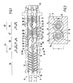
- each rotor 5, 6 Disposed on each rotor 5, 6 are from the left to the right side in Fig. 1 screw elements 12 with two flights, elements 13 each with two forward-conveying wings 14, 15, elements 16 each with two backward-conveying wings 17, 18, elements 19 each with two forward-conveying wings 21, 22, elements 23 each with two backward-conveying wings 24, 25, ring-like throttle elements 26, screw elements 27 with three flights, elements 28 each with three forward-conveying wings 30, 31, 32, elements 33 each with three backward-conveying wings 34, 35, 36, and screw elements 37 with three flights.
- the elements 12, 13, 16, 19, 23, 27, 28, 33 and 37 may be fixed to the rotor shafts by splining. However, it is also possible to make the complete rotor in one piece, e.g. in forged steel.
- the throttle valve 40 is formed by rotary slot bars 41 extending across the rotors 5, 6 and rotating in a semi-circular depression 42 in the barrels 3, 4.
- the screw elements 12 form a first conveying section 34 for feeding the material from the supply port 7 downward to a first mixing section 44 which comprises a first mixing zone 45 and a second mixing zone 46.
- Each mixing zone 45, 46 has two forward-conveying wings 14, 15 and 21, 22, respectively, and two backward-conveying wings 17, 18 and 24, 25, respectively, on each rotor 5, 6.
- the first mixing section 44 mainly dispersive mixing takes place, so that the particles of the powder material to be mixed are broken up.
- the material is molten mainly due to shear forces and partly by external heating.
- the first mixing zone 45 the polymer material starts to melt and continues to melt in the second mixing zone 46.
- the molten material flows to screw elements 27 which form a second conveying section 47 and feed the molten material to a second mixing section 48 which comprises only one mixing zone 49 which has three forward-conveying wings 30, 31, 32 and three backward-conveying wings 34, 35, 36 on each rotor 5, 6.
- the second mixing section 48 mainly distributive mixing occurs, that is, the melt is kneaded further to distribute the different polymers, fillers, additives and so forth homogeneously in the melt.
- the polymer melt is discharged through discharge port 8.
- the upstream ends of the forward-conveying wings 14, 15 of the first mixing zone 45 of the first mixing section 44 are positioned at the downstream ends of the flights of the screws 12 of the first conveying section 34, and the upstream ends of the forward-conveying wings 30, 31, 32 of the mixing zone 49 of the second mixing section 48 are positioned at the downstream ends of the flights of the screws 27 of the second conveying section 47.
- the forward-conveying wings 14, 15 and 21, 22, respectively, and the upstream ends of the backward-conveying wings 17, 18 and 24, 25, respectively, are offset with an angle of 90° in the circumferential direction, and the downstream ends of the backward-conveying wings 17, 18 of the first mixing zone 45 and the upstream ends of the forward-conveying wings 24, 25 of the second mixing zone are also offset by an angle of 90° in the circumferential direction to form a passage for the material to be mixed.
- downstream ends of the forward-conveying wings 30, 31, 32 and the backward-conveying wings 34, 35, 36 of the mixing zone 49 of the second mixing section 48 are positioned to form a "V".
- the axial lengths L1, L3 and L5 of the forward-conveying wings 14, 15; 21, 22; 30, 31, 32 is longer than the length L2, L4 and L6 of the backward-conveying wings 17, 18; 24, 25; 34, 35, 36. Furthermore, the length L2 of the backward-conveying wings 17, 18 in the first mixing zone 45 is shorter than the length L4 of the backward-conveying wings 24, 25 in the second mixing zone 46 of the first mixing section 44.
- the lead or pitch of the wings 14, 15; 17, 18; 21, 22; 24, 25; 30, 31, 32; 34, 35, 36 is for instance 4, and, usually, the same for all wings.
- the radial clearance C of the wings 14, 15; 17, 18 of the first mixing zone 45 is greater than the radial clearance C of the wings 21, 22; 24, 25 in the second mixing zone 46 of the first mixing section 44.
- the radial clearance C may vary between 0.01 and 0.05 D.
- the tip width W of the wings 14, 15, 17, 18, 21, 22, 24, 25, 30, 31, 32, 34, 35, 36 may vary between 0.01 and 0.05 D.
- the counter-rotating twin screw extruder as shown in Fig. 1 was used having a barrel diameter D of 90 mm, a length of the chamber 2 before the throttle valve 40 of 7.5 and after the throttle valve 40 of 3.5 based on the diameter D of the barrels, and equipped with a gear pump at the discharge port and a pelletizer.
- the number of the wings 14, 15, 17, 18, 21, 22 and 24, 25 of the first mixing section 44 was 2, the number of the wings 30, 31, 32 and 34, 35, 36 of the mixing zone 41 of the second mixing section 48 was 3.
- Screws 12 had two flights and screws 27 three.
- the radial clearance C was 3.9 mm for the forward-conveying wings 14, 15 and backward-conveying wings 17, 18 of the first mixing zone 45, 2.0 mm for the forward-conveying wings 21, 22 and backward-conveying wings 24, 25 of the second mixing zone 46 and 1.5 mm for the forward-conveying wings 30, 31, 32 and backward-conveying wings 34, 35, 36 of the second mixing section 48.
- polymer material bimodal polyethylene prepared according to Inventive Material C of Example 3 of WO 00/22040 was used, except that 1-butene was used as a comonomer instead of 1-hexene and the hydrogen to ethylene ratio in the loop reactor was adjusted so that the polymer produced in the loop reactor had an MFR 2 of 400g/10 min.
- the 1-butene to ethylene ratio in the gas phase reactor was adjusted so that the density of the resin was 0.951 g/cm 3 and hydrogen to ethylene ratio in the gas phase reactor was adjusted so that the bimodal polymer resin had a melt index MFR 5 of 0.25 g/10 min and MFR 21 of 9.5 g/10 min, where MFR 5 and MFR 21 were determined according to ISO 1133:1997, conditions T and G, respectively. Density was determined according to ISO 1183-1987.
- Into the polymer material were added about 2.3% by weight carbon black and about 0.35% of antioxidants and stabilisers. The polymer material was fed with a throughput of about 240 kg/h.
- the SEI was calculated on the basis of the power consumption of the drive motor.
- the white spots of the product were rated according to ISO 11420: 1996 (E).
- Example 1 was repeated with an extruder having the same barrel diameter, L/D ratios, throttle valve and other equipment. However, it had only one mixing section upstream the throttle valve.
- the mixing section consisted of two forward-conveying wing elements followed by a backward-conveying wing element. All wing elements had 2 flights, a radial clearance of 2 mm, a lead of 4 and an L/D ratio of 1.
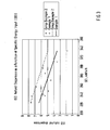
- Example 1 The results of Example 1 in comparison to Example 2 are shown in Fig. 3. It is evident from Fig. 3 that the inventive concept makes it possible to reach a given homogeneity level of the polymer with a lower specific energy input (SEI). This reduces the risk of degradation of the polymer and thereby a combination of good mechanical properties and good homogeneity can be achieved.
- SEI specific energy input
- Example 1 was repeated with a larger extruder having a barrel diameter D of 380 mm.
- the throughput was 24 t/h.
- the polymer material and all other parameters were the same as in Example 1.
- the rating for the homogeneity according to the method ISO 11420: 1996 (E) was 5.2, the SEI 215 kWh/t.
- Comparative Example 2 was repeated with a larger extruder having a barrel diameter D of 380 mm as in Example 3. All other parameters of the extruder were the same as in Comparative Example 3. The throughput and the polymer material were the same as in Example 3. The rating for the homogeneity according to ISO 11420: 1996 (E) was 7.2, the SEI 245 kwh/t.
- Example 3 was repeated, except that another polymer was used.
- the polymer was prepared otherwise in a similar way than in Example 1, but the gas phase reactor conditions were adjusted so that the bimodal polymer had MFR 5 of 0.25 g/10 min and MFR 21 of 6.7 g/10 min.
- the rating according to the method ISO 11420: 1996 (E) was 4.4; the SEI was 210 kWh/t.
- Example 5 was repeated, except that another polymer was used.
- the polymer was prepared otherwise in a similar way than in Example 1, but the gas phase reactor conditions were adjusted so that the bimodal polymer had MFR 5 of 0.30 g/10 min and MFR 21 of 11 g/10 min.
- the rating according to ISO 11420: 1996 (E) was 2.9, the SEI was 195 kWh/t.
- Example 5 was repeated, except that another polymer was used.
- the polymer was prepared otherwide in a similar way than in Example 1, but the gas phase reactor conditions were adjusted so that the bimodal polmer had MFR 2 of 0.50 g/10 min and MFR 5 of 2.0 g/10 min and density of 0.942 g/cm 3 , where MFR 2 and MFR 5 were determined according to ISO 1133:1997, conditions D and T, respectively.
- the rating according to ISO 11420: 1996 (E) was 1.2, the SEI was 200 kWh/t.
Landscapes
- Engineering & Computer Science (AREA)
- Mechanical Engineering (AREA)
- Processing And Handling Of Plastics And Other Materials For Molding In General (AREA)
- Extrusion Moulding Of Plastics Or The Like (AREA)
- Mixers Of The Rotary Stirring Type (AREA)
Abstract
Description
- The invention relates to a counter-rotating twin screw extruder for compounding polymers.
- When producing a polymer composition, the ingredients thereof, as different polymers, fillers and additives, as anti-oxidants, light stabilizers, etc., have to be mixed intimately in order to obtain a composition as homogenous as possible. This is done by compounding the ingredients in a compounding machine as a counter-rotating twin-screw extruder.
- While on one hand, the compounding should be carried out at a high temperature and shearing rate in order to achieve a homogenous composition, degradation of the polymers is caused by too severe conditions.
- Particular problems are encountered when compounding multimodal polymers, as multimodal polyethylene materials. Multimodal polymers are in many respects superior to corresponding mono-modal materials. Multimodal polyethylene materials and, more particularly, bimodal polyethylene materials have a widespread and increasing use as materials for various applications as pipes, wires and cables, films, blow-molded and injection-molded articles, etc.
- Multimodal polymer compositions such as bimodal polyethylene materials consist of a low molecular weight polymer fraction and a high molecular weight fraction. The high molecular weight molecules are known to be most sensitive to the compounding conditions needed to achieve the desired degree of homogenization.
- For instance, undispersed domains of high molecular weight molecules appear as white spots in colored materials. The white spots may adversely affect the strength of the article. Further, when compounding polymer compositions, e.g. for the production of a film, gel particles appear as disfiguring spots in the finished film which consist of high molecular weight polymer not adequately compounded. Although compounding at higher temperatures and shear rates may remove the white spots and gel particles, degradation of the high molecular weight molecules may occur which negatively effects the otherwise superior properties of the multimodal polymer material.
- Thus, the white spots and gel particles are a serious problem in the polymer industry and a solution of the problem would mean the removal of a serious obstacle to use otherwise superior multimodal polymer compositions.
- In EP-A-645 232 is described a way of reducing this problem by adding liquid nitrogen or solid carbon dioxide to the polymer feed. This is, however, a rather costly way. According to WO 98/15591, the problems may be tackled by compounding at a low shear rate so that the temperature of the polymer increases slowly. This requires a highly precise control of the process conditions of the counter-rotating twin screw extruder, however, and the production capacity is rather low.
- US-A-6,409,373 discloses a counter-rotating twin-screw extruder having a mixing section upstream of and a mixing section downstream of a throttle valve or gate plates, each mixing section comprising forward-conveying wings and backward-conveying wings downstream of the forward-conveying wings. Although in a monomodal polymer material the number of gels may be reduced, it is not possible to obtain multimodal polymer materials of high homogeneity without adversely affecting the superior quality of multimodal polymer materials with the known extruder.
- It is an object of the invention to obtain multimodal polymer materials of high homogeneity with a high production capacity at low cost.
- This object is attained with the counter-rotating twin-screw extruder according to
claim 1 for compounding. - The counter-rotating twin extruder according to the invention comprises a mixing section having at least two mixing zones, each mixing zone consisting of at least one, preferably at least two forward-conveying wings and at least one, preferably at least two backward-conveying wings downstream of the forward-conveying wings on each rotor.
- The number of forward-conveying wings and the number of backward-conveying wings of each mixing zone preferably corresponds to the number of flights of the screws of the conveying section upstream of the mixing section. For instance, in each mixing zone two, three or four forward-conveying wings and backward-conveying wings, respectively, may be used.
- To adjust the filling degree of the mixing section, a throttle valve or gate is usually provided between the mixing section and the discharge port of the extruder. Instead of a throttle valve, a gear pump connected to the discharge valve may be used to control the filling degree in the mixing section. As a throttle valve, a rotary slot bar may be used as disclosed in JP-A-3004647. In that solution two bars extend across the rotors which have a convex side rotating in a concave depression in the barrels, the throttle gap being defined by the distance between the rotors and the throttle edge of the bars.
- Although the twin screw extruder of the present invention may have only one mixing section, it is preferred to have two mixing sections, namely one upstream of the throttle valve and one downstream thereof. Whereas the first mixing section upstream of the throttle valve comprises preferably at least two mixing zones, each mixing zone having preferably at least two forward-conveying wings and at least two backward-conveying wings, the second mixing section downstream of the throttle valve has preferably a lower number of mixing zones, for instance only one mixing zone when the first mixing section has two mixing zones.
- In the first mixing section, mainly dispersive mixing takes place, so that the particles of the powder material to be mixed are broken up, whereas in the second mixing section, mainly distributive mixing occurs. That is, in the first mixing zone of the first mixing section next to the screws of the conveying section, the polymer material starts to melt and continues to melt in the second mixing zone of the first mixing section, and then the polymer melt is charged through the throttle valve into the second mixing section. There, the melt is kneaded further to distribute the different polymers and optionally, fillers, additives and so forth homogeneously in the melt. Due to its high dispersive mixing efficiency of the at least two mixing zones of the first mixing section, the twin screw extruder of the invention is particularly effective for compounding multimodal polymer materials.
- From the second mixing section, the polymer melt is discharged through the discharge port into a gear pump or a discharge extruder. From the gear pump or the discharge extruder, the melt is passed through a die plate, after which it is cooled and cut to pellets. Alternatively, the melt is discharged through a discharge port directly after the first mixing section.
- Whereas the filling degree of the first mixing section is determined by the throttle valve, the filling of the second mixing section downstream of the throttle valve may be adjusted by the suction side pressure of the gear pump.
- Preferably, the upstream ends of the forward-conveying wings of the first mixing zone of the first mixing section are positioned at the downstream end of the screws of the first conveying section, and it is also preferred that the upstream ends of the forward-conveying wings of the mixing zone of the second mixing section are positioned at the downstream ends of the of the screws of the second conveying section. That is, the screws of the first and second conveying sections and the forward-conveying wings of the first zone of the first mixing section and of the mixing zone of the second mixing section, respectively, preferably are positioned to form continuous closed flights.
- In the first mixing section, the downstream end of the forward-conveying wings and the upstream end of the backward-conveying wings of each mixing zone are preferably offset to form a passage for the material to be mixed. Due to these passages, a mixing action in axial direction occurs, and it is avoided that material, in particular unmelted material, is pressed between the barrels and the wings on the rotors, which would cause a deflection of the rotors resulting in a non-uniform mixing due to a non-uniform gap between the wings and the barrels.
- The offset between the forward-conveying wings and the backward-conveying wings of each mixing zone usually depends on the number of flights of the screw in the conveying section. In case of two flights, the offset may be about 90° in the circumferential direction, and in case of three flights, about 60°.
- In the first mixing section, the downstream ends of the forward-conveying wings and the upstream ends of the backward-conveying wings of one mixing zone and the downstream ends of the backward-conveying wings of one mixing zone and the upstream ends of the forward-conveying wings of the next mixing zone are positioned in the same radial plane, respectively. However, an axial shift of those ends is also possible, so that for instance in one mixing zone the upward ends of the backward-conveying wings are upstream of the downstream ends of the forward-conveying wings of this zone. Forming those passages between the wings is particularly preferred when the screws of the first conveying section have only two flights. In case of three flights or more, the rotor is stiffer so that the downstream ends of the forward-conveying wings and the upstream ends of the backward conveying wings of each mixing zone may be connected to form a "V". Because the viscosity of the polymer melt is lower in the second mixing section due to higher temperature, the forward-conveying wings and the backward-conveying wings of the mixing zone of the second mixing section form such Vs. That is, the forward-conveying wings and the backward-conveying wings of the second mixing section are preferably positioned to form continuous closed flights having the shape of a "V".
- The length of the forward-conveying wings is preferably longer than that of the backward-conveying wings in each mixing zone, and the length of the backward-conveying wings in the first mixing zone of the first mixing section is preferably shorter than the length of the backward-conveying wings in the mixing zone of the first mixing section downstream of the first mixing zone.
- The ratio of the length (L) of the wings to the inner diameter (D) of the barrels is preferably between 0.3 and 2.0. For instance the L/D ratio of the forward-conveying wings of both mixing sections is about 1, the L/D ratio of the backward conveying wings of the first mixing zone of the first mixing section and the second mixing section about 1 /2 and the L/D ratio of the backward-conveying wings of the second mixing zone of the first mixing section is about 3/4.
- The lead or pitch of the wings of the mixing sections may vary between 2 and 6D and usually all wings have the same lead. If there is different lead along the screw, then normally in each mixing zone there is the same lead.
- The radial clearance of the wings of the first mixing zone of the first mixing section is preferably greater than the radial clearance of the wings of the second mixing zone of the first mixing section, and the radial clearance of the wings of the second mixing section is preferably smaller than the clearance of the conveying wings of the second mixing zone of the first mixing section. That is, the more the material melts and the lower its viscosity, the smaller is the radial clearance. Based on the inner diameter (D) of the barrels, the radial clearance may vary between 0.01 and 0.05 D. Usually, the radial clearance of the forward-conveying wings and the backward-conveying wings of one mixing zone are equal to obtain uniform balanced mixing. The tip width of the conveying wings may vary between 0.01 and 0.05 D.
- Whereas the two barrels form a common chamber in which the rotors counter-rotate, no or only slight intermeshing takes place between the two rotors.
- When compounding polymer with a twin screw extruder of the present invention, at a given specific energy input (SEI), the homogeneity of the product is considerably improved. Thus, the degradation of polymer chains is significantly reduced, which leads to an improvement of the optical and mechanical properties of the compounded product, especially long-term mechanical properties as slow-crack growth resistance, i.e. resistance to internal pressure, exemplified by pipe pressure testing.
- In addition, the control of SEI by adjusting the throttle valve is more conventient. While the prior art rotor design may give large variation of SEI with a minor adjustment of the throttle valve in some positions of the valve, the present design gives a nearly uniform and controllable response of SEI over the whole adjustment range of the throttle valve. This makes it easier to balance between a desired homogeneity and SEI level to avoid degradation of the polymer.
- The twin screw extruder of the present invention is particularly useful for compounding multimodal polymer compositions, particularly compositions comprising a low molecular weight ethylene polymer, for instance with a melt flow rate MFR2 (D)of about 0.1 to 5,000 g/10 min, and a high molecular weight polymer, for instance with a MFR21 (G) of 0.01 to 10.0 g/10 min, where MFR2 (D) and MFR21 (G) are determined according to ISO 1133,
conditions - The compounded product is particularly useful for making coloured bimodal polyethylene pipe materials comprising the bimodal ethylene polymer as a base resin and the pigment, optionally as compounded into a carrier polymer in the form of a master batch. The coloured materials preferably have a high homogeneity rating of 5 or less, more preferably 3 or less, and still more preferably 2 or less, where the homogeneity is defined as the dispersion of white spots measured according to the method ISO 11420: 1996 (E) which method is normally used for evaluation of carbon black agglomerates in polyolefin pipes. Suitable pigments are, among others, carbon black, ultramarine blue and phtalocyanine blue. Of these, carbon black is especially preferred. In addition, the pipes have excellent mechanical properties and anti-sagging properties. Also high-density polyethylene films with excellent optical properties may be obtained, as well as large blow-molded articles and wire and cable products such as the slotted cores of optical cables. Said bimodal pipe materials are disclosed in WO 00/01765 and WO 00/22040, said bimodal film materials are disclosed in WO 99/51649, said bimodal blow-molding materials are disclosed in WO 01/14122 and said slotted core materials in WO 02/063345.
- An embodiment of the inventive twin screw extruder will be explained in more detail below with reference to the enclosed drawing, in which:
- Fig. 1
- shows a longitudinal section through the extruder;
- Fig. 2
- shows a cross-section along the line II-II in Fig. 1; and
- Fig. 3
- shows a graph of the dispersion as a function of specific energy input.
- According to Fig. 1 and 2, the extruder has a
body 1 forming achamber 2 comprising tocylindrical barrels barrel rotor - On the upper side at the left end or upstream side of the extruder shown in Fig. 1 a
supply port 7, shown with a dotted line, is provided to supply the powder material to be mixed inchamber 2. At the right hand or downstream side of the extruder in Fig. 1 adischarge port 8 is provided for discharging the mixed molten material into a gear pump from which it is passed through a die plate, after which it is cooled and solified and cut to pellets (not shown). - The two
rotors - Disposed on each
rotor screw elements 12 with two flights,elements 13 each with two forward-conveyingwings elements 16 each with two backward-conveyingwings elements 19 each with two forward-conveyingwings elements 23 each with two backward-conveyingwings 24, 25, ring-like throttle elements 26, screw elements 27 with three flights,elements 28 each with three forward-conveyingwings elements 33 each with three backward-conveyingwings elements 37 with three flights. Theelements - The
throttle valve 40 is formed by rotary slot bars 41 extending across therotors barrels - The
screw elements 12 form a first conveyingsection 34 for feeding the material from thesupply port 7 downward to afirst mixing section 44 which comprises afirst mixing zone 45 and asecond mixing zone 46. Each mixingzone wings wings rotor - In the
first mixing section 44, mainly dispersive mixing takes place, so that the particles of the powder material to be mixed are broken up. In thefirst mixing section 44, the material is molten mainly due to shear forces and partly by external heating. In thefirst mixing zone 45, the polymer material starts to melt and continues to melt in thesecond mixing zone 46. - From the
throttle valve 40 the molten material flows to screw elements 27 which form a second conveyingsection 47 and feed the molten material to asecond mixing section 48 which comprises only one mixingzone 49 which has three forward-conveyingwings wings rotor second mixing section 48, mainly distributive mixing occurs, that is, the melt is kneaded further to distribute the different polymers, fillers, additives and so forth homogeneously in the melt. From thesecond mixing section 48, the polymer melt is discharged throughdischarge port 8. - The upstream ends of the forward-conveying
wings first mixing zone 45 of thefirst mixing section 44 are positioned at the downstream ends of the flights of thescrews 12 of the first conveyingsection 34, and the upstream ends of the forward-conveyingwings zone 49 of thesecond mixing section 48 are positioned at the downstream ends of the flights of the screws 27 of the second conveyingsection 47. - In the
first mixing section 44 in each mixingzone wings wings wings first mixing zone 45 and the upstream ends of the forward-conveyingwings 24, 25 of the second mixing zone are also offset by an angle of 90° in the circumferential direction to form a passage for the material to be mixed. - In contrast to this, the downstream ends of the forward-conveying
wings wings zone 49 of thesecond mixing section 48 are positioned to form a "V". - The axial lengths L1, L3 and L5 of the forward-conveying
wings wings wings first mixing zone 45 is shorter than the length L4 of the backward-conveyingwings 24, 25 in thesecond mixing zone 46 of thefirst mixing section 44. Thus, the ratio of the length of the wings to the inner barrel diameter D is, for instance L1/D=L3/D=L5/D=1, L2/D=0.5, L4/D=0.75 and L6/D=0.5. - The lead or pitch of the
wings instance 4, and, usually, the same for all wings. - In the
first mixing section 44, the radial clearance C of thewings first mixing zone 45 is greater than the radial clearance C of thewings second mixing zone 46 of thefirst mixing section 44. Based on the diameter D of thebarrels - The tip width W of the
wings - The counter-rotating twin screw extruder as shown in Fig. 1 was used having a barrel diameter D of 90 mm, a length of the
chamber 2 before thethrottle valve 40 of 7.5 and after thethrottle valve 40 of 3.5 based on the diameter D of the barrels, and equipped with a gear pump at the discharge port and a pelletizer. - The number of the
wings first mixing section 44 was 2, the number of thewings second mixing section 48 was 3.Screws 12 had two flights and screws 27 three. The radial clearance C was 3.9 mm for the forward-conveyingwings wings first mixing zone 45, 2.0 mm for the forward-conveyingwings wings 24, 25 of thesecond mixing zone 46 and 1.5 mm for the forward-conveyingwings wings second mixing section 48. The lead was 4 for all wings and the L/D ratios were L1/D=L3/D=L5/D=1; L2/D=0.5; L4/D=0.75 and L6/D=0.5. - As polymer material bimodal polyethylene prepared according to Inventive Material C of Example 3 of WO 00/22040 was used, except that 1-butene was used as a comonomer instead of 1-hexene and the hydrogen to ethylene ratio in the loop reactor was adjusted so that the polymer produced in the loop reactor had an MFR2 of 400g/10 min. Further, the 1-butene to ethylene ratio in the gas phase reactor was adjusted so that the density of the resin was 0.951 g/cm3 and hydrogen to ethylene ratio in the gas phase reactor was adjusted so that the bimodal polymer resin had a melt index MFR5 of 0.25 g/10 min and MFR21 of 9.5 g/10 min, where MFR5 and MFR21 were determined according to ISO 1133:1997, conditions T and G, respectively. Density was determined according to ISO 1183-1987. Into the polymer material were added about 2.3% by weight carbon black and about 0.35% of antioxidants and stabilisers. The polymer material was fed with a throughput of about 240 kg/h. The SEI was calculated on the basis of the power consumption of the drive motor. The white spots of the product were rated according to ISO 11420: 1996 (E).
- Example 1 was repeated with an extruder having the same barrel diameter, L/D ratios, throttle valve and other equipment. However, it had only one mixing section upstream the throttle valve. The mixing section consisted of two forward-conveying wing elements followed by a backward-conveying wing element. All wing elements had 2 flights, a radial clearance of 2 mm, a lead of 4 and an L/D ratio of 1.
- The same polymer material with the same throughput was used as in Example 1.
- The results of Example 1 in comparison to Example 2 are shown in Fig. 3. It is evident from Fig. 3 that the inventive concept makes it possible to reach a given homogeneity level of the polymer with a lower specific energy input (SEI). This reduces the risk of degradation of the polymer and thereby a combination of good mechanical properties and good homogeneity can be achieved.
- Example 1 was repeated with a larger extruder having a barrel diameter D of 380 mm. The throughput was 24 t/h. The polymer material and all other parameters were the same as in Example 1. The rating for the homogeneity according to the method ISO 11420: 1996 (E) was 5.2, the SEI 215 kWh/t.
- Comparative Example 2 was repeated with a larger extruder having a barrel diameter D of 380 mm as in Example 3. All other parameters of the extruder were the same as in Comparative Example 3. The throughput and the polymer material were the same as in Example 3. The rating for the homogeneity according to ISO 11420: 1996 (E) was 7.2, the SEI 245 kwh/t.
- Example 3 was repeated, except that another polymer was used. The polymer was prepared otherwise in a similar way than in Example 1, but the gas phase reactor conditions were adjusted so that the bimodal polymer had MFR5 of 0.25 g/10 min and MFR21 of 6.7 g/10 min.
- The rating according to the method ISO 11420: 1996 (E) was 4.4; the SEI was 210 kWh/t.
- Example 5 was repeated, except that another polymer was used. The polymer was prepared otherwise in a similar way than in Example 1, but the gas phase reactor conditions were adjusted so that the bimodal polymer had MFR5 of 0.30 g/10 min and MFR21 of 11 g/10 min. The rating according to ISO 11420: 1996 (E) was 2.9, the SEI was 195 kWh/t.
- Example 5 was repeated, except that another polymer was used. The polymer was prepared otherwide in a similar way than in Example 1, but the gas phase reactor conditions were adjusted so that the bimodal polmer had MFR2 of 0.50 g/10 min and MFR5 of 2.0 g/10 min and density of 0.942 g/cm3, where MFR2 and MFR5 were determined according to ISO 1133:1997, conditions D and T, respectively. The rating according to ISO 11420: 1996 (E) was 1.2, the SEI was 200 kWh/t.
- Examples 5 to 7 were repeated with the big extruder according to Comparative Example 4.
- The ratings according to ISO 11420: 1996 (E) were 7.2; 4.4 and 1.6, respectively, the SEI were 240, 230 and 245 kWh/t, respectively.
Claims (15)
- Screw extruder having a body (1) forming a chamber (2) of two barrels (3, 4) housing two counter-rotating axis-parallel rotors (5, 6), a supply port (7) for the material to be mixed in the chamber (2) at one end of the body (1), a discharge port (8) for discharging the mixed material at the other end of the body (1), a conveying section (34) with screws (12) for feeding the material from the supply port (7) downstream to a mixing section (44) which comprises at least two mixing zones (45, 46), each mixing zone (45, 46) having at least one forward-conveying wing (14, 15; 21, 22) and at least one backward-conveying wing (17, 18; 24, 25) downstream of the forward-conveying wing (14, 15; 21, 22) on each rotor (5, 6).
- The twin screw extruder according to claim 1 characterized in that the downstream ends of the forward-conveying wings (14, 15; 21, 22) and the upstream ends of the backward-conveying wings (17, 18; 24, 25) of each mixing zone (45, 46) are offset to form a passage for the material to be mixed.
- The twin screw extruder according to claim 1 or 2 characterized in that the downstream ends of the backward-conveying wings (17, 18) of the first mixing zone (45) on the side of the conveying section (34) and the upstream ends of the forward-conveying wings (21, 22) of the mixing zone (46) downstream of the first mixing zone (45) are offset to form a passage for the material to be mixed.
- The twin screw extruder according to any one of the preceding claims characterized in that the length (L2) of the backward-conveying wings (17, 18) in the first mixing zone (45) is shorter than the length (L4) of the backward-conveying wings (24, 25) in the mixing zone (46) downstream of the first mixing zone (45).
- The twin screw extruder according to any one of the preceding claims characterized in that the radial clearance (C) of the wings (11, 14; 17, 18) of the first mixing zone (45) is greater than the radial clearance (C) of the wings (21, 22; 24, 25) of the mixing zone (46) downstream of the first mixing zone (45).
- The twin screw extruder according to any one of the preceding claims characterized in that a throttle valve (40) is provided in the chamber (2) downstream of the mixing section (44).
- The twin screw extruder according to claim 6 characterized in that downstream of the throttle valve (40) a second conveying section (47) with screws (27) and a second mixing section (48) are provided.
- The twin screw extruder according to claim 7 characterized in that the second mixing section (48) comprises at least one mixing zone (49) consisting of at least one forward-conveying wing (30, 31, 32) and at least one backward-conveying wing (34, 35, 36) downstream of the forward-conveying wing (30, 31, 32).
- The twin screw extruder according to claim 6 or 7 characterized in that the forward-conveying wings (30, 31, 32) and the backward-conveying wings (34, 35, 36) of the mixing zone (49) of the second mixing section (48) are positioned to form continous flights in the shape of a "V".
- The twin screw extruder according to any one of the preceding claims characterized in that the number of the forward-conveying wings (14, 15; 21, 22; 30, 31, 32) and of the backward-conveying wings (17, 18; 24, 25; 34, 35, 36) of each mixing zone (45, 46, 49) corresponds to the number of the flights of the screws (12, 27) of the conveying sections (34, 47) upstream of the respective mixing zone (45, 46, 49).
- The twin screw extruder according to any one of the preceding claims characterized in that the length (L1, L3, L5) of the forward-conveying wings (14, 15; 21, 22; 30, 31, 32) of each mixing zone (45, 46, 49) is longer than the length (L2, L4, L6) of the backward-conveying wings (17, 18; 24, 25; 34, 35, 36) of said mixing zone (45, 46, 49).
- The twin screw extruder according to any one of the preceding claims characterized in that the ratio of the length (L1 to L6) of the wings (14, 15; 17, 18; 21, 22; 24, 25; 30, 31, 32; 34, 35, 36) to the barrel diameter (D) is 0.3 to 2.0.
- The twin screw extruder according to any one of the preceding claims characterized in that the lead of the wings (14, 15; 17, 18; 21, 22; 24, 25; 30, 31, 32; 34, 35, 36) of the first mixing section (44) and/or the second mixing section (48) is 2 to 6 times the barrel diameter (D).
- Use of the twin screw extruder according to any one of the preceding claims for compounding multimodal polymer compositions.
- Use according to claim 14 characterized in that the specific energy input for compounding a multimodal olefin polymer is lower than 300 kWh/t.
Priority Applications (4)
| Application Number | Priority Date | Filing Date | Title |
|---|---|---|---|
| DE602004015424T DE602004015424D1 (en) | 2004-05-24 | 2004-05-24 | Use of a counter-rotating twin screw extruder for the fusion of multimodal polymer compositions |
| ES04012265T ES2306939T3 (en) | 2004-05-24 | 2004-05-24 | USE OF A DOUBLE CHROME EXTRUDER FOR THE MULTIMODAL POLYMER COMPOUND MIXTURE. |
| AT04012265T ATE402805T1 (en) | 2004-05-24 | 2004-05-24 | USE OF AN COUNTER-ROTATING TWIN-SCREW EXTRUDER FOR FUSING MULTIMODAL POLYMER COMPOSITIONS |
| EP04012265A EP1600276B1 (en) | 2004-05-24 | 2004-05-24 | Use of a counter-rotating twin screw extruder for compounding multimodal polymer compositions |
Applications Claiming Priority (1)
| Application Number | Priority Date | Filing Date | Title |
|---|---|---|---|
| EP04012265A EP1600276B1 (en) | 2004-05-24 | 2004-05-24 | Use of a counter-rotating twin screw extruder for compounding multimodal polymer compositions |
Publications (2)
| Publication Number | Publication Date |
|---|---|
| EP1600276A1 true EP1600276A1 (en) | 2005-11-30 |
| EP1600276B1 EP1600276B1 (en) | 2008-07-30 |
Family
ID=34925109
Family Applications (1)
| Application Number | Title | Priority Date | Filing Date |
|---|---|---|---|
| EP04012265A Expired - Lifetime EP1600276B1 (en) | 2004-05-24 | 2004-05-24 | Use of a counter-rotating twin screw extruder for compounding multimodal polymer compositions |
Country Status (4)
| Country | Link |
|---|---|
| EP (1) | EP1600276B1 (en) |
| AT (1) | ATE402805T1 (en) |
| DE (1) | DE602004015424D1 (en) |
| ES (1) | ES2306939T3 (en) |
Cited By (48)
| Publication number | Priority date | Publication date | Assignee | Title |
|---|---|---|---|---|
| EP2130862A1 (en) | 2008-06-02 | 2009-12-09 | Borealis AG | Polymer compositions and pressure-resistant pipes made thereof |
| EP2130859A1 (en) | 2008-06-02 | 2009-12-09 | Borealis AG | Polymer compositions having improved homogeneity and odour, a method for making them and pipes made thereof |
| EP2182524A1 (en) | 2008-10-31 | 2010-05-05 | Borealis AG | Cable and Polymer composition comprising a multimodal ethylene copolymer |
| EP2182525A1 (en) | 2008-10-31 | 2010-05-05 | Borealis AG | Cable and polymer composition comprising a multimodal ethylene copolymer |
| EP2182526A1 (en) | 2008-10-31 | 2010-05-05 | Borealis AG | Cable and polymer composition comprising an multimodal ethylene copolymer |
| EP2186833A1 (en) | 2008-11-17 | 2010-05-19 | Borealis AG | Multi-stage process for producing polytheylene with lowered gel formation |
| EP2223943A1 (en) | 2009-02-25 | 2010-09-01 | Borealis AG | Multimodal polymer of propylene, composition containing the same and a process for manufacturing the same |
| EP2256159A1 (en) | 2009-05-26 | 2010-12-01 | Borealis AG | Polymer composition for crosslinked pipes |
| EP2256158A1 (en) | 2009-05-26 | 2010-12-01 | Borealis AG | Polymer composition for crosslinked articles |
| EP2860203A1 (en) | 2013-10-10 | 2015-04-15 | Borealis AG | Multistage process for producing polyethylene compositions |
| WO2015086812A1 (en) | 2013-12-13 | 2015-06-18 | Borealis Ag | Multistage process for producing polyethylene compositions |
| WO2016118566A1 (en) * | 2015-01-21 | 2016-07-28 | Univation Technologies, Llc | Methods for gel reduction in polyolefins |
| EP3103818A1 (en) | 2015-06-12 | 2016-12-14 | Borealis AG | Method and apparatus for polymerising olefins in gas phase |
| EP3109261A1 (en) | 2015-06-23 | 2016-12-28 | Borealis AG | Process for producing lldpe resins |
| US9539556B2 (en) | 2014-02-28 | 2017-01-10 | Borealis Ag | Process for polymerizing olefins in a fluidized bed |
| EP3184167A1 (en) | 2015-12-22 | 2017-06-28 | Borealis AG | A method for returning polymer to a fluidised bed reactor |
| EP3184166A1 (en) | 2015-12-22 | 2017-06-28 | Borealis AG | A method for withdrawing agglomerates from a fluidised bed reactor |
| US9790290B2 (en) | 2014-02-28 | 2017-10-17 | Borealis Ag | Gas phase polymerization process |
| WO2017207493A1 (en) | 2016-05-31 | 2017-12-07 | Borealis Ag | Polymer composition and a process for production of the polymer composition |
| WO2017220558A1 (en) | 2016-06-22 | 2017-12-28 | Borealis Ag | Polymer composition and a process for production of the polymer composition |
| US20180021877A1 (en) * | 2016-07-21 | 2018-01-25 | Ut-Ba Ttelle, Llc | Electromagnetic print nozzle having an extruder for direct-write additive manufacturing |
| WO2018060029A1 (en) | 2016-09-28 | 2018-04-05 | Borealis Ag | Process for producing a coated pipe |
| US9951213B2 (en) | 2013-12-13 | 2018-04-24 | Borealis Ag | Multistage process for producing polyethylene compositions |
| WO2018095788A1 (en) | 2016-11-25 | 2018-05-31 | Borealis Ag | A process for producing polyolefin film composition and films prepared thereof |
| WO2018095772A2 (en) | 2016-11-25 | 2018-05-31 | Borealis Ag | New composition and process |
| EP3275612A4 (en) * | 2015-03-27 | 2018-08-15 | The Japan Steel Works, Ltd. | Multi-shaft kneading machine |
| EP3385958A1 (en) | 2017-04-06 | 2018-10-10 | Borealis AG | Cable jacket composition |
| EP3385959A1 (en) | 2017-04-06 | 2018-10-10 | Borealis AG | Cable jacket composition |
| EP3418309A1 (en) | 2017-06-20 | 2018-12-26 | Borealis AG | A method, an arrangement and use of an arrangement of preparing polymer |
| EP3418308A1 (en) | 2017-06-20 | 2018-12-26 | Borealis AG | A method, an arrangement and use of an arrangement for olefin polymerisation |
| EP3418330A1 (en) | 2017-06-21 | 2018-12-26 | Borealis AG | Polymer composition and a process for production of the polymer composition |
| EP3418310A1 (en) | 2017-06-23 | 2018-12-26 | Borealis AG | Process and apparatus for removing polymer material from a gas-solids olefin polymerization reactor |
| US10308737B2 (en) | 2014-09-30 | 2019-06-04 | Borealis Ag | Process for polymerising ultra-high molecular weight polyethylene |
| EP3502090A1 (en) | 2017-12-20 | 2019-06-26 | 3M Innovative Properties Company | Process for the manufacturing of a compound comprising a (meth)acryloyl group |
| EP3567061A1 (en) | 2018-05-09 | 2019-11-13 | Borealis AG | Polypropylene pipe composition |
| WO2019238428A1 (en) | 2018-06-14 | 2019-12-19 | Borealis Ag | Process for polymerizing olefin in a gas phase reactor with improved thermal homogeneity |
| WO2020136165A1 (en) | 2018-12-28 | 2020-07-02 | Borealis Ag | A process for producing polyolefin film composition and films prepared thereof |
| WO2020136164A1 (en) | 2018-12-28 | 2020-07-02 | Borealis Ag | A process for producing polyolefin film composition and films prepared thereof |
| CN111516226A (en) * | 2020-04-30 | 2020-08-11 | 福建玮晟机械有限公司 | Synthetic membrane plastify film forming device |
| US10850236B2 (en) | 2015-08-31 | 2020-12-01 | Palo Alto Research Center Incorporated | Low dispersion, fast response mixing device |
| US10968156B2 (en) | 2017-12-20 | 2021-04-06 | 3M Innovative Properties Company | Process for the manufacturing of a 3-halopropionyl halide in a flow reactor |
| WO2021142903A1 (en) * | 2020-01-15 | 2021-07-22 | 五邑大学 | Counter rotating extrusion device, extruder and material manufacturing method |
| EP3868793A1 (en) | 2020-02-24 | 2021-08-25 | Borealis AG | Process for producing alpha-olefin polymers in a multistage polymerization process |
| WO2022258804A1 (en) | 2021-06-11 | 2022-12-15 | Borealis Ag | A process for producing a multimodal ethylene polymer and films prepared therefrom |
| EP4257640A1 (en) | 2022-04-04 | 2023-10-11 | Borealis AG | Pipe comprising a polypropylene composition |
| EP4344869A1 (en) | 2022-09-30 | 2024-04-03 | Borealis AG | Multimodal ethylene copolymer composition and films comprising the same |
| EP4403598A1 (en) | 2023-01-23 | 2024-07-24 | Borealis AG | Polymer composition comprising recycled low density polyethylene for packaging applications |
| EP4650754A1 (en) | 2024-05-13 | 2025-11-19 | Borealis GmbH | Method for calibration, method for in-line quality control in a compounding process based on nir and apparatus with nir quality control |
Families Citing this family (1)
| Publication number | Priority date | Publication date | Assignee | Title |
|---|---|---|---|---|
| US11845814B2 (en) | 2022-02-01 | 2023-12-19 | Chevron Phillips Chemical Company Lp | Ethylene polymerization processes and reactor systems for the production of multimodal polymers using combinations of a loop reactor and a fluidized bed reactor |
Citations (5)
| Publication number | Priority date | Publication date | Assignee | Title |
|---|---|---|---|---|
| US3565403A (en) * | 1968-09-05 | 1971-02-23 | Intercole Automation Inc | Continuous mixer |
| JPS5631433A (en) | 1979-08-21 | 1981-03-30 | Japan Steel Works Ltd:The | 2-stage and 2-shaft continuous kneader |
| JPS56136633A (en) | 1980-03-27 | 1981-10-26 | Kobe Steel Ltd | Twin-shaft continuous type kneading device |
| WO1999051649A1 (en) * | 1998-04-06 | 1999-10-14 | Borealis Technology Oy | High density polyethylene compositions, a process for the production thereof and films prepared thereof |
| US6280074B1 (en) * | 1999-11-08 | 2001-08-28 | Kobe Steel, Ltd. | Continuous mixer |
-
2004
- 2004-05-24 EP EP04012265A patent/EP1600276B1/en not_active Expired - Lifetime
- 2004-05-24 DE DE602004015424T patent/DE602004015424D1/en not_active Expired - Lifetime
- 2004-05-24 ES ES04012265T patent/ES2306939T3/en not_active Expired - Lifetime
- 2004-05-24 AT AT04012265T patent/ATE402805T1/en not_active IP Right Cessation
Patent Citations (5)
| Publication number | Priority date | Publication date | Assignee | Title |
|---|---|---|---|---|
| US3565403A (en) * | 1968-09-05 | 1971-02-23 | Intercole Automation Inc | Continuous mixer |
| JPS5631433A (en) | 1979-08-21 | 1981-03-30 | Japan Steel Works Ltd:The | 2-stage and 2-shaft continuous kneader |
| JPS56136633A (en) | 1980-03-27 | 1981-10-26 | Kobe Steel Ltd | Twin-shaft continuous type kneading device |
| WO1999051649A1 (en) * | 1998-04-06 | 1999-10-14 | Borealis Technology Oy | High density polyethylene compositions, a process for the production thereof and films prepared thereof |
| US6280074B1 (en) * | 1999-11-08 | 2001-08-28 | Kobe Steel, Ltd. | Continuous mixer |
Non-Patent Citations (4)
| Title |
|---|
| DATABASE WPI Section Ch Week 198120, Derwent World Patents Index; Class A31, AN 1981-35285D, XP002302346 * |
| DATABASE WPI Section Ch Week 198149, Derwent World Patents Index; Class A31, AN 1981-90057D, XP002302347 * |
| PATENT ABSTRACTS OF JAPAN vol. 0050, no. 85 (C - 057) 3 June 1981 (1981-06-03) * |
| PATENT ABSTRACTS OF JAPAN vol. 0060, no. 11 (C - 088) 22 January 1982 (1982-01-22) * |
Cited By (88)
| Publication number | Priority date | Publication date | Assignee | Title |
|---|---|---|---|---|
| EP2130859A1 (en) | 2008-06-02 | 2009-12-09 | Borealis AG | Polymer compositions having improved homogeneity and odour, a method for making them and pipes made thereof |
| EP2130862A1 (en) | 2008-06-02 | 2009-12-09 | Borealis AG | Polymer compositions and pressure-resistant pipes made thereof |
| US8461266B2 (en) | 2008-10-31 | 2013-06-11 | Borealis Ag | Cable and polymer composition comprising a multimodal ethylene copolymer |
| EP2182524A1 (en) | 2008-10-31 | 2010-05-05 | Borealis AG | Cable and Polymer composition comprising a multimodal ethylene copolymer |
| EP2182525A1 (en) | 2008-10-31 | 2010-05-05 | Borealis AG | Cable and polymer composition comprising a multimodal ethylene copolymer |
| EP2182526A1 (en) | 2008-10-31 | 2010-05-05 | Borealis AG | Cable and polymer composition comprising an multimodal ethylene copolymer |
| US10087296B2 (en) | 2008-10-31 | 2018-10-02 | Boreaus Ag | Method of producing a cable comprising a multimodal ethylene copolymer |
| EP2186833A1 (en) | 2008-11-17 | 2010-05-19 | Borealis AG | Multi-stage process for producing polytheylene with lowered gel formation |
| EP2223943A1 (en) | 2009-02-25 | 2010-09-01 | Borealis AG | Multimodal polymer of propylene, composition containing the same and a process for manufacturing the same |
| WO2010097409A1 (en) | 2009-02-25 | 2010-09-02 | Borealis Ag | Multimodal polymer of propylene, composition containing the same and a process for manufacturing the same |
| US9562631B2 (en) | 2009-05-26 | 2017-02-07 | Borealis Ag | Polymer composition for crosslinked articles |
| WO2010136374A1 (en) | 2009-05-26 | 2010-12-02 | Borealis Ag | Polymer composition for crosslinked articles |
| WO2010136373A1 (en) | 2009-05-26 | 2010-12-02 | Borealis Ag | Polymer composition for crosslinked pipes |
| EP2256158A1 (en) | 2009-05-26 | 2010-12-01 | Borealis AG | Polymer composition for crosslinked articles |
| EP2256159A1 (en) | 2009-05-26 | 2010-12-01 | Borealis AG | Polymer composition for crosslinked pipes |
| US9708479B2 (en) | 2013-10-10 | 2017-07-18 | Borealis Ag | Multistage process for producing polyethylene compositions |
| EP2860203A1 (en) | 2013-10-10 | 2015-04-15 | Borealis AG | Multistage process for producing polyethylene compositions |
| WO2015086812A1 (en) | 2013-12-13 | 2015-06-18 | Borealis Ag | Multistage process for producing polyethylene compositions |
| US9951213B2 (en) | 2013-12-13 | 2018-04-24 | Borealis Ag | Multistage process for producing polyethylene compositions |
| US10000592B2 (en) | 2013-12-13 | 2018-06-19 | Borealis Ag | Multistage process for producing polyethylene compositions |
| US9539556B2 (en) | 2014-02-28 | 2017-01-10 | Borealis Ag | Process for polymerizing olefins in a fluidized bed |
| US9790290B2 (en) | 2014-02-28 | 2017-10-17 | Borealis Ag | Gas phase polymerization process |
| US10308737B2 (en) | 2014-09-30 | 2019-06-04 | Borealis Ag | Process for polymerising ultra-high molecular weight polyethylene |
| WO2016118566A1 (en) * | 2015-01-21 | 2016-07-28 | Univation Technologies, Llc | Methods for gel reduction in polyolefins |
| US10682797B2 (en) | 2015-01-21 | 2020-06-16 | Univation Technologies, Llc | Methods for gel reduction in polyolefins |
| EP3275612A4 (en) * | 2015-03-27 | 2018-08-15 | The Japan Steel Works, Ltd. | Multi-shaft kneading machine |
| WO2016198631A1 (en) | 2015-06-12 | 2016-12-15 | Borealis Ag | Method and apparatus for polymerising olefins in gas phase |
| EP3103818A1 (en) | 2015-06-12 | 2016-12-14 | Borealis AG | Method and apparatus for polymerising olefins in gas phase |
| EP3109261A1 (en) | 2015-06-23 | 2016-12-28 | Borealis AG | Process for producing lldpe resins |
| US10584196B2 (en) | 2015-06-23 | 2020-03-10 | Borealis Ag | Process for producing LLDPE resins |
| WO2016207270A1 (en) | 2015-06-23 | 2016-12-29 | Borealis Ag | Process for producing lldpe resins |
| US10850236B2 (en) | 2015-08-31 | 2020-12-01 | Palo Alto Research Center Incorporated | Low dispersion, fast response mixing device |
| US11904277B2 (en) | 2015-08-31 | 2024-02-20 | Xerox Corporation | Low dispersion, fast response mixing device |
| US11111324B2 (en) | 2015-12-22 | 2021-09-07 | Borealis Ag | Method for withdrawing agglomerates from a fluidized bed polymerization reactor |
| EP3184166A1 (en) | 2015-12-22 | 2017-06-28 | Borealis AG | A method for withdrawing agglomerates from a fluidised bed reactor |
| EP3184167A1 (en) | 2015-12-22 | 2017-06-28 | Borealis AG | A method for returning polymer to a fluidised bed reactor |
| US10961334B2 (en) | 2016-05-31 | 2021-03-30 | Borealis Ag | Polymer composition and a process for production of the polymer composition |
| WO2017207493A1 (en) | 2016-05-31 | 2017-12-07 | Borealis Ag | Polymer composition and a process for production of the polymer composition |
| WO2017220558A1 (en) | 2016-06-22 | 2017-12-28 | Borealis Ag | Polymer composition and a process for production of the polymer composition |
| US20180021877A1 (en) * | 2016-07-21 | 2018-01-25 | Ut-Ba Ttelle, Llc | Electromagnetic print nozzle having an extruder for direct-write additive manufacturing |
| WO2018060029A1 (en) | 2016-09-28 | 2018-04-05 | Borealis Ag | Process for producing a coated pipe |
| US10899942B2 (en) | 2016-09-28 | 2021-01-26 | Borealis Ag | Process for producing a coated pipe |
| WO2018095790A1 (en) | 2016-11-25 | 2018-05-31 | Borealis Ag | A process for producing polyolefin film composition and films prepared thereof |
| US11180586B2 (en) | 2016-11-25 | 2021-11-23 | Borealis Ag | Process for producing polyolefin film composition and films prepared thereof |
| US11427670B2 (en) | 2016-11-25 | 2022-08-30 | Borealis Ag | Composition and process |
| WO2018095788A1 (en) | 2016-11-25 | 2018-05-31 | Borealis Ag | A process for producing polyolefin film composition and films prepared thereof |
| WO2018095772A2 (en) | 2016-11-25 | 2018-05-31 | Borealis Ag | New composition and process |
| US10982025B2 (en) | 2016-11-25 | 2021-04-20 | Borealis Ag | Process for producing polyolefin film composition and films prepared thereof |
| WO2018185274A1 (en) | 2017-04-06 | 2018-10-11 | Borealis Ag | Cable jacket composition |
| EP3385958A1 (en) | 2017-04-06 | 2018-10-10 | Borealis AG | Cable jacket composition |
| WO2018185273A1 (en) | 2017-04-06 | 2018-10-11 | Borealis Ag | Cable jacket composition |
| EP3385959A1 (en) | 2017-04-06 | 2018-10-10 | Borealis AG | Cable jacket composition |
| US11208507B2 (en) | 2017-06-20 | 2021-12-28 | Borealis Ag | Method, an arrangement and use of an arrangement for olefin polymerisation |
| WO2018234175A1 (en) | 2017-06-20 | 2018-12-27 | Borealis Ag | A method, an arrangement and use of an arrangement of preparing polymer |
| WO2018234176A1 (en) | 2017-06-20 | 2018-12-27 | Borealis Ag | A method, an arrangement and use of an arrangement for olefin polymerisation |
| US11220558B2 (en) | 2017-06-20 | 2022-01-11 | Borealis Ag | Method, an arrangement and use of an arrangement of preparing polymer |
| EP3418308A1 (en) | 2017-06-20 | 2018-12-26 | Borealis AG | A method, an arrangement and use of an arrangement for olefin polymerisation |
| EP3418309A1 (en) | 2017-06-20 | 2018-12-26 | Borealis AG | A method, an arrangement and use of an arrangement of preparing polymer |
| WO2018234110A1 (en) | 2017-06-21 | 2018-12-27 | Borealis Ag | Polymer composition and a process for production of the polymer composition |
| EP3418330A1 (en) | 2017-06-21 | 2018-12-26 | Borealis AG | Polymer composition and a process for production of the polymer composition |
| US11254809B2 (en) | 2017-06-21 | 2022-02-22 | Borealis Ag | Polymer composition and a process for production of the polymer composition |
| WO2018233999A1 (en) | 2017-06-23 | 2018-12-27 | Borealis Ag | Process and apparatus for removing polymer material from a gas-solids olefin polymerization reactor |
| EP3418310A1 (en) | 2017-06-23 | 2018-12-26 | Borealis AG | Process and apparatus for removing polymer material from a gas-solids olefin polymerization reactor |
| US10927064B2 (en) | 2017-12-20 | 2021-02-23 | 3M Innovative Properties Company | Process for the manufacturing of a compound comprising a (meth)acryloyl group |
| US10968156B2 (en) | 2017-12-20 | 2021-04-06 | 3M Innovative Properties Company | Process for the manufacturing of a 3-halopropionyl halide in a flow reactor |
| WO2019123125A1 (en) | 2017-12-20 | 2019-06-27 | 3M Innovative Properties Company | Process for the manufacturing of a compound comprising a (meth)acryloyl group |
| EP3502090A1 (en) | 2017-12-20 | 2019-06-26 | 3M Innovative Properties Company | Process for the manufacturing of a compound comprising a (meth)acryloyl group |
| WO2019215108A1 (en) | 2018-05-09 | 2019-11-14 | Borealis Ag | Polypropylene pipe composition |
| US12134688B2 (en) | 2018-05-09 | 2024-11-05 | Borealis Ag | Polypropylene pipe composition |
| EP3567061A1 (en) | 2018-05-09 | 2019-11-13 | Borealis AG | Polypropylene pipe composition |
| US12018102B2 (en) | 2018-06-14 | 2024-06-25 | Borealis Ag | Process for polymerizing olefin in a gas phase reactor with improved thermal homogeneity |
| WO2019238428A1 (en) | 2018-06-14 | 2019-12-19 | Borealis Ag | Process for polymerizing olefin in a gas phase reactor with improved thermal homogeneity |
| WO2020136165A1 (en) | 2018-12-28 | 2020-07-02 | Borealis Ag | A process for producing polyolefin film composition and films prepared thereof |
| WO2020136164A1 (en) | 2018-12-28 | 2020-07-02 | Borealis Ag | A process for producing polyolefin film composition and films prepared thereof |
| WO2021142903A1 (en) * | 2020-01-15 | 2021-07-22 | 五邑大学 | Counter rotating extrusion device, extruder and material manufacturing method |
| EP3868793A1 (en) | 2020-02-24 | 2021-08-25 | Borealis AG | Process for producing alpha-olefin polymers in a multistage polymerization process |
| WO2021170552A1 (en) | 2020-02-24 | 2021-09-02 | Borealis Ag | Process for producing alpha-olefin polymers in a multistage polymerization process |
| CN111516226A (en) * | 2020-04-30 | 2020-08-11 | 福建玮晟机械有限公司 | Synthetic membrane plastify film forming device |
| CN111516226B (en) * | 2020-04-30 | 2021-11-12 | 福建玮晟机械有限公司 | Synthetic membrane plastify film forming device |
| WO2022258804A1 (en) | 2021-06-11 | 2022-12-15 | Borealis Ag | A process for producing a multimodal ethylene polymer and films prepared therefrom |
| EP4257640A1 (en) | 2022-04-04 | 2023-10-11 | Borealis AG | Pipe comprising a polypropylene composition |
| WO2023194276A1 (en) | 2022-04-04 | 2023-10-12 | Borealis Ag | Pipe comprising a polypropylene composition |
| WO2024068977A1 (en) | 2022-09-30 | 2024-04-04 | Borealis Ag | Multimodal ethylene copolymer composition and films comprising the same |
| EP4344869A1 (en) | 2022-09-30 | 2024-04-03 | Borealis AG | Multimodal ethylene copolymer composition and films comprising the same |
| EP4403598A1 (en) | 2023-01-23 | 2024-07-24 | Borealis AG | Polymer composition comprising recycled low density polyethylene for packaging applications |
| WO2024156640A1 (en) | 2023-01-23 | 2024-08-02 | Borealis Ag | Polymer composition comprising recycled low density polyethylene for packaging applications |
| EP4650754A1 (en) | 2024-05-13 | 2025-11-19 | Borealis GmbH | Method for calibration, method for in-line quality control in a compounding process based on nir and apparatus with nir quality control |
| WO2025237913A1 (en) | 2024-05-13 | 2025-11-20 | Borealis Gmbh | Method for calibration, method for in-line quality control in a compounding process based on nir and apparatus with nir quality control |
Also Published As
| Publication number | Publication date |
|---|---|
| DE602004015424D1 (en) | 2008-09-11 |
| EP1600276B1 (en) | 2008-07-30 |
| ES2306939T3 (en) | 2008-11-16 |
| ATE402805T1 (en) | 2008-08-15 |
Similar Documents
| Publication | Publication Date | Title |
|---|---|---|
| EP1600276B1 (en) | Use of a counter-rotating twin screw extruder for compounding multimodal polymer compositions | |
| US8079747B2 (en) | Counter-rotating twin screw extruder | |
| AU644992B2 (en) | Continuous mixing of elastomeric compounds | |
| US6818173B1 (en) | Polymeric blends formed by solid state shear pulverization and having improved melt flow properties | |
| CN1119198C (en) | Mixing device | |
| US6280074B1 (en) | Continuous mixer | |
| GB2260335A (en) | Process for producing composite reinforced polypropylene resin composition | |
| Stade | Techniques for compounding glass fiber‐reinforced thermoplastics | |
| Verbraak et al. | Screw design in injection molding | |
| WO2011135745A1 (en) | Method for producing composite pellet for extrusion molding, and composite pellet for extrusion molding produced by the method | |
| EP1864775A1 (en) | Method of producing carbon microfiber-containing resin composition | |
| CN100425430C (en) | Mixing element/section of a screw in a plastification apparatus | |
| US5573332A (en) | Screw element for a screw-like extrusion machine | |
| EP1419041B1 (en) | Mixing and kneading device for polymer compositions | |
| EP0645232A1 (en) | Method for compounding a polymerized alpha-olefin resin | |
| US3486193A (en) | Apparatus for extruding thermoplastic material | |
| CN109294045A (en) | A kind of anti-electrostatic fire retardant masterbatch and preparation method thereof | |
| CN117227138A (en) | A twin-screw extruder and preparation method of high-load polyolefin masterbatch | |
| US20100168335A1 (en) | Method for producing polymer mixtures | |
| WO2012137665A1 (en) | Process for producing pellets of glass-fiber-reinforced thermoplastic resin composition | |
| Todd et al. | Twin screw reinforced plastics compounding | |
| US20110001261A1 (en) | Extruder and process for extruding a polymer | |
| CN215396788U (en) | Screw assembly for producing starch-based full-biodegradable material | |
| JPS6246208B2 (en) | ||
| CN113895016B (en) | Double-screw combination and processing technology for melting modification processing of polyvinyl alcohol material |
Legal Events
| Date | Code | Title | Description |
|---|---|---|---|
| PUAI | Public reference made under article 153(3) epc to a published international application that has entered the european phase |
Free format text: ORIGINAL CODE: 0009012 |
|
| 17P | Request for examination filed |
Effective date: 20040524 |
|
| AK | Designated contracting states |
Kind code of ref document: A1 Designated state(s): AT BE BG CH CY CZ DE DK EE ES FI FR GB GR HU IE IT LI LU MC NL PL PT RO SE SI SK TR |
|
| AX | Request for extension of the european patent |
Extension state: AL HR LT LV MK |
|
| AKX | Designation fees paid |
Designated state(s): AT BE BG CH CY CZ DE DK EE ES FI FR GB GR HU IE IT LI LU MC NL PL PT RO SE SI SK TR |
|
| 17Q | First examination report despatched |
Effective date: 20060213 |
|
| GRAP | Despatch of communication of intention to grant a patent |
Free format text: ORIGINAL CODE: EPIDOSNIGR1 |
|
| RTI1 | Title (correction) |
Free format text: USE OF A COUNTER-ROTATING TWIN SCREW EXTRUDER FOR COMPOUNDING MULTIMODAL POLYMER COMPOSITIONS |
|
| GRAS | Grant fee paid |
Free format text: ORIGINAL CODE: EPIDOSNIGR3 |
|
| GRAA | (expected) grant |
Free format text: ORIGINAL CODE: 0009210 |
|
| AK | Designated contracting states |
Kind code of ref document: B1 Designated state(s): AT BE BG CH CY CZ DE DK EE ES FI FR GB GR HU IE IT LI LU MC NL PL PT RO SE SI SK TR |
|
| REG | Reference to a national code |
Ref country code: GB Ref legal event code: FG4D |
|
| REG | Reference to a national code |
Ref country code: CH Ref legal event code: EP |
|
| REF | Corresponds to: |
Ref document number: 602004015424 Country of ref document: DE Date of ref document: 20080911 Kind code of ref document: P |
|
| REG | Reference to a national code |
Ref country code: IE Ref legal event code: FG4D |
|
| REG | Reference to a national code |
Ref country code: ES Ref legal event code: FG2A Ref document number: 2306939 Country of ref document: ES Kind code of ref document: T3 |
|
| PG25 | Lapsed in a contracting state [announced via postgrant information from national office to epo] |
Ref country code: PT Free format text: LAPSE BECAUSE OF FAILURE TO SUBMIT A TRANSLATION OF THE DESCRIPTION OR TO PAY THE FEE WITHIN THE PRESCRIBED TIME-LIMIT Effective date: 20081230 Ref country code: NL Free format text: LAPSE BECAUSE OF FAILURE TO SUBMIT A TRANSLATION OF THE DESCRIPTION OR TO PAY THE FEE WITHIN THE PRESCRIBED TIME-LIMIT Effective date: 20080730 |
|
| PG25 | Lapsed in a contracting state [announced via postgrant information from national office to epo] |
Ref country code: AT Free format text: LAPSE BECAUSE OF FAILURE TO SUBMIT A TRANSLATION OF THE DESCRIPTION OR TO PAY THE FEE WITHIN THE PRESCRIBED TIME-LIMIT Effective date: 20080730 Ref country code: BG Free format text: LAPSE BECAUSE OF FAILURE TO SUBMIT A TRANSLATION OF THE DESCRIPTION OR TO PAY THE FEE WITHIN THE PRESCRIBED TIME-LIMIT Effective date: 20081030 Ref country code: SI Free format text: LAPSE BECAUSE OF FAILURE TO SUBMIT A TRANSLATION OF THE DESCRIPTION OR TO PAY THE FEE WITHIN THE PRESCRIBED TIME-LIMIT Effective date: 20080730 Ref country code: FI Free format text: LAPSE BECAUSE OF FAILURE TO SUBMIT A TRANSLATION OF THE DESCRIPTION OR TO PAY THE FEE WITHIN THE PRESCRIBED TIME-LIMIT Effective date: 20080730 |
|
| PG25 | Lapsed in a contracting state [announced via postgrant information from national office to epo] |
Ref country code: EE Free format text: LAPSE BECAUSE OF FAILURE TO SUBMIT A TRANSLATION OF THE DESCRIPTION OR TO PAY THE FEE WITHIN THE PRESCRIBED TIME-LIMIT Effective date: 20080730 Ref country code: DK Free format text: LAPSE BECAUSE OF FAILURE TO SUBMIT A TRANSLATION OF THE DESCRIPTION OR TO PAY THE FEE WITHIN THE PRESCRIBED TIME-LIMIT Effective date: 20080730 |
|
| PG25 | Lapsed in a contracting state [announced via postgrant information from national office to epo] |
Ref country code: SK Free format text: LAPSE BECAUSE OF FAILURE TO SUBMIT A TRANSLATION OF THE DESCRIPTION OR TO PAY THE FEE WITHIN THE PRESCRIBED TIME-LIMIT Effective date: 20080730 Ref country code: CZ Free format text: LAPSE BECAUSE OF FAILURE TO SUBMIT A TRANSLATION OF THE DESCRIPTION OR TO PAY THE FEE WITHIN THE PRESCRIBED TIME-LIMIT Effective date: 20080730 Ref country code: RO Free format text: LAPSE BECAUSE OF FAILURE TO SUBMIT A TRANSLATION OF THE DESCRIPTION OR TO PAY THE FEE WITHIN THE PRESCRIBED TIME-LIMIT Effective date: 20080730 |
|
| PLBE | No opposition filed within time limit |
Free format text: ORIGINAL CODE: 0009261 |
|
| STAA | Information on the status of an ep patent application or granted ep patent |
Free format text: STATUS: NO OPPOSITION FILED WITHIN TIME LIMIT |
|
| 26N | No opposition filed |
Effective date: 20090506 |
|
| PG25 | Lapsed in a contracting state [announced via postgrant information from national office to epo] |
Ref country code: IT Free format text: LAPSE BECAUSE OF FAILURE TO SUBMIT A TRANSLATION OF THE DESCRIPTION OR TO PAY THE FEE WITHIN THE PRESCRIBED TIME-LIMIT Effective date: 20080730 |
|
| PG25 | Lapsed in a contracting state [announced via postgrant information from national office to epo] |
Ref country code: MC Free format text: LAPSE BECAUSE OF NON-PAYMENT OF DUE FEES Effective date: 20090531 |
|
| REG | Reference to a national code |
Ref country code: CH Ref legal event code: PL |
|
| GBPC | Gb: european patent ceased through non-payment of renewal fee |
Effective date: 20090524 |
|
| PG25 | Lapsed in a contracting state [announced via postgrant information from national office to epo] |
Ref country code: LI Free format text: LAPSE BECAUSE OF NON-PAYMENT OF DUE FEES Effective date: 20090531 Ref country code: CH Free format text: LAPSE BECAUSE OF NON-PAYMENT OF DUE FEES Effective date: 20090531 Ref country code: SE Free format text: LAPSE BECAUSE OF FAILURE TO SUBMIT A TRANSLATION OF THE DESCRIPTION OR TO PAY THE FEE WITHIN THE PRESCRIBED TIME-LIMIT Effective date: 20081030 |
|
| REG | Reference to a national code |
Ref country code: FR Ref legal event code: ST Effective date: 20100129 |
|
| REG | Reference to a national code |
Ref country code: IE Ref legal event code: MM4A |
|
| PG25 | Lapsed in a contracting state [announced via postgrant information from national office to epo] |
Ref country code: FR Free format text: LAPSE BECAUSE OF NON-PAYMENT OF DUE FEES Effective date: 20090602 Ref country code: IE Free format text: LAPSE BECAUSE OF NON-PAYMENT OF DUE FEES Effective date: 20090524 |
|
| PG25 | Lapsed in a contracting state [announced via postgrant information from national office to epo] |
Ref country code: PL Free format text: LAPSE BECAUSE OF FAILURE TO SUBMIT A TRANSLATION OF THE DESCRIPTION OR TO PAY THE FEE WITHIN THE PRESCRIBED TIME-LIMIT Effective date: 20080730 Ref country code: GB Free format text: LAPSE BECAUSE OF NON-PAYMENT OF DUE FEES Effective date: 20090524 |
|
| PG25 | Lapsed in a contracting state [announced via postgrant information from national office to epo] |
Ref country code: GR Free format text: LAPSE BECAUSE OF FAILURE TO SUBMIT A TRANSLATION OF THE DESCRIPTION OR TO PAY THE FEE WITHIN THE PRESCRIBED TIME-LIMIT Effective date: 20081031 |
|
| PG25 | Lapsed in a contracting state [announced via postgrant information from national office to epo] |
Ref country code: LU Free format text: LAPSE BECAUSE OF NON-PAYMENT OF DUE FEES Effective date: 20090524 |
|
| PG25 | Lapsed in a contracting state [announced via postgrant information from national office to epo] |
Ref country code: HU Free format text: LAPSE BECAUSE OF FAILURE TO SUBMIT A TRANSLATION OF THE DESCRIPTION OR TO PAY THE FEE WITHIN THE PRESCRIBED TIME-LIMIT Effective date: 20090131 |
|
| PG25 | Lapsed in a contracting state [announced via postgrant information from national office to epo] |
Ref country code: TR Free format text: LAPSE BECAUSE OF FAILURE TO SUBMIT A TRANSLATION OF THE DESCRIPTION OR TO PAY THE FEE WITHIN THE PRESCRIBED TIME-LIMIT Effective date: 20080730 |
|
| PG25 | Lapsed in a contracting state [announced via postgrant information from national office to epo] |
Ref country code: CY Free format text: LAPSE BECAUSE OF FAILURE TO SUBMIT A TRANSLATION OF THE DESCRIPTION OR TO PAY THE FEE WITHIN THE PRESCRIBED TIME-LIMIT Effective date: 20080730 |
|
| PGFP | Annual fee paid to national office [announced via postgrant information from national office to epo] |
Ref country code: ES Payment date: 20150527 Year of fee payment: 12 Ref country code: DE Payment date: 20150521 Year of fee payment: 12 |
|
| PGFP | Annual fee paid to national office [announced via postgrant information from national office to epo] |
Ref country code: BE Payment date: 20150520 Year of fee payment: 12 |
|
| PG25 | Lapsed in a contracting state [announced via postgrant information from national office to epo] |
Ref country code: BE Free format text: LAPSE BECAUSE OF NON-PAYMENT OF DUE FEES Effective date: 20160531 |
|
| REG | Reference to a national code |
Ref country code: DE Ref legal event code: R119 Ref document number: 602004015424 Country of ref document: DE |
|
| PG25 | Lapsed in a contracting state [announced via postgrant information from national office to epo] |
Ref country code: DE Free format text: LAPSE BECAUSE OF NON-PAYMENT OF DUE FEES Effective date: 20161201 |
|
| PG25 | Lapsed in a contracting state [announced via postgrant information from national office to epo] |
Ref country code: ES Free format text: LAPSE BECAUSE OF NON-PAYMENT OF DUE FEES Effective date: 20160525 |
|
| REG | Reference to a national code |
Ref country code: ES Ref legal event code: FD2A Effective date: 20181204 |