EP3247538B1 - Outils électriques contenant des mécanismes de verrouillage et procédé de mise en prise de tels mécanismes de verrouillage - Google Patents
Outils électriques contenant des mécanismes de verrouillage et procédé de mise en prise de tels mécanismes de verrouillage Download PDFInfo
- Publication number
- EP3247538B1 EP3247538B1 EP15878382.9A EP15878382A EP3247538B1 EP 3247538 B1 EP3247538 B1 EP 3247538B1 EP 15878382 A EP15878382 A EP 15878382A EP 3247538 B1 EP3247538 B1 EP 3247538B1
- Authority
- EP
- European Patent Office
- Prior art keywords
- holder
- drive blade
- pins
- notches
- locking mechanism
- Prior art date
- Legal status (The legal status is an assumption and is not a legal conclusion. Google has not performed a legal analysis and makes no representation as to the accuracy of the status listed.)
- Active
Links
- 230000007246 mechanism Effects 0.000 title claims description 50
- 238000000034 method Methods 0.000 title claims description 16
- 230000001419 dependent effect Effects 0.000 claims description 2
- 239000000463 material Substances 0.000 description 3
- 238000002485 combustion reaction Methods 0.000 description 2
- 239000000956 alloy Substances 0.000 description 1
- 229910045601 alloy Inorganic materials 0.000 description 1
- 230000005540 biological transmission Effects 0.000 description 1
- 238000010276 construction Methods 0.000 description 1
- 230000007704 transition Effects 0.000 description 1
Images


Classifications
-
- B—PERFORMING OPERATIONS; TRANSPORTING
- B25—HAND TOOLS; PORTABLE POWER-DRIVEN TOOLS; MANIPULATORS
- B25C—HAND-HELD NAILING OR STAPLING TOOLS; MANUALLY OPERATED PORTABLE STAPLING TOOLS
- B25C1/00—Hand-held nailing tools; Nail feeding devices
- B25C1/04—Hand-held nailing tools; Nail feeding devices operated by fluid pressure, e.g. by air pressure
- B25C1/047—Mechanical details
-
- B—PERFORMING OPERATIONS; TRANSPORTING
- B25—HAND TOOLS; PORTABLE POWER-DRIVEN TOOLS; MANIPULATORS
- B25C—HAND-HELD NAILING OR STAPLING TOOLS; MANUALLY OPERATED PORTABLE STAPLING TOOLS
- B25C1/00—Hand-held nailing tools; Nail feeding devices
- B25C1/008—Safety devices
Definitions
- the present invention relates to power tools, and more specifically to powered fastener drivers.
- fastener drivers known in the art for driving fasteners (e.g., nails, tacks, staples, etc.) into a workpiece.
- These fastener drivers operate utilizing various means known in the art (e.g., compressed air generated by an air compressor, electrical energy, flywheel mechanisms), but often these designs uses simple locking mechanisms for preventing accidental operations of the trigger and thus unwanted and often dangerous fastener propulsion.
- Such simple locking mechanisms often are not reliable over time, as they are easy to wear out and result in malfunctioning of the locking mechanism.
- WO-A-2014/011508 describes a fastener-driving tool including a combustion power source configured for powering a driver blade drive system for reciprocal movement of a driver blade relative to a workpiece.
- the driver blade drive system includes a first portion configured such that the combustion power source linearly drives a driver blade towards the workpiece, and a second portion configured such that the driver blade is rotated relative to the workpiece.
- the invention provides, in one aspect, a power tool for driving a fastener including a cylinder; a drive piston within the cylinder, the drive piston being acted on by a driving force resulting from a pressure difference, the drive piston being moveable between an initial position and a driving position; a drive blade coupled to the drive piston and operable to drive a fastener; wherein the power tool includes a locking mechanism that operates through engagement between at least two catches and at least two locking members.
- the at least two catches are at least two notches which are integrally formed on the drive blade.
- one of the at least two notches including a ramp.
- the at least two notches are formed on a side of the drive blade.
- the at least two locking members are at least two pins which are mounted with a holder which is separated from the drive blade.
- the pins have a circular or an ellipsoidal cross section.
- the engagement between the at least two pins and the at least two notches are dependent on the holder's location.
- the holder is biased by a resiliently deformable member, which is mounted between a tab portion of the holder and a structural portion of the power tool.
- the holder is pivotable between a locking position and an unlocking position.
- the holder pivots in a first direction that the at least two pins move away from the at least two notches when the holder's tab is pressed by a trip member.
- the holder pivots in a second direction that the at least two pins move closer to the at least two notches when the holder's tab is separated from the trip member.
- the at least two pins disengages from the at least two notches when the holder pivots in the first direction
- the at least two pins attempt to engage the at least two notches when the holder pivots in the second direction.
- a first one of the at least two pins will engage with the at least two notches and the second one of the at least two pins will only engage with one of the at least two notches.
- the invention provides, in another aspect, a method for engagement of a locking mechanism which including urging a drive blade locked by a locking mechanism to a driving position so as to drive a fastener; urging a holder to a first direction and moving at least two locking members away from at least two catches for disengaging the locking mechanism so that the drive blade can be operated for driving a fastener.
- the at least two locking members are at least two pins which are mounted with a holder which is separated from the drive blade.
- the at least two locking members are at least two pins which are mounted with a holder which is separated from the drive blade.
- oone of the at least two notches including a ramp.
- the pins have a circular or an ellipsoidal cross section.
- the invention provides, in yet another aspect, A method for engagement of a locking mechanism which including urging a drive blade to an initial position so as to engage a locking mechanism; urging a holder to a second direction; moving the at least two locking members closer to the at least two catches so that during the drive blade's return travel, at least one of the locking members is in contact with one of the at least two catches on the drive blade and positioning the at least two locking members with a respective catch for engaging the locking mechanism.
- the at least two locking members are at least two pins which are mounted with a holder which is separated from the drive blade.
- the at least two catches are at least two notches which are integrally formed on the drive blade.
- one of the at least two notches including a ramp.
- the pins have a circular or an ellipsoidal cross section.
- the method including altering the holder's position so as to control engagement between the pins and the notches.
- the method for engagement of the locking mechanism which including engaging at least two locking members with a respective catch so as to lock the drive blade to prevent accidental movement of the drive blade; engaging a first locking member with a first notch then shifting the first locking member out of the first notch from the ramp; engaging the first locking member with a second notch whilst engaging a second locking member with the first notch so as complete the locking mechanism engagement.
- the current invention including a locking mechanism that can securely restrict the movement of the drive blade for preventing unintended driving of fasteners.
- a locking mechanism that can securely restrict the movement of the drive blade for preventing unintended driving of fasteners.
- the longevity of this locking mechanism is therefore greatly improved from the convention locking mechanism where generally only one engagement point is used for locking.
- the force being exerted onto the locking members are practically halved which would result in more than doubling of each locking member's durability.
- Both pins are now working well under their critical yield strength so the chance of these pins failing has been greatly reduced.
- the double action pin/notch mechanism makes an additional safety measure, that in case of one of the pins is broken there is still another pin which can at least provide temporary locking function to the blade in the operation.
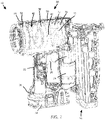
- Fig. 1 illustrates a vacuum powered fastener driver 10 operable to drive fasteners such as nails, tacks, staples and etc. held within a magazine 14 into a work piece.
- the fastener driver 10 includes an outer housing 18 with a handle portion 22, and a user-actuated trigger 26 mounted on the handle portion 22.
- the fastener driver 10 does not require an external source of air pressure, but rather includes an on-board vacuum system 30 as shown in Fig.2 .
- the vacuum system 30 is powered by a power source such as a battery pack 34, which is coupled to a battery attachment portion 38 of the outer housing 18.
- alternative power sources such as an electrical cord may be used to provide power to the vacuum system 30.
- the fastener driver includes a drive blade 42 actuated by the vacuum system 30 to drive the fasteners into a work piece.
- the vacuum system 30 includes a variable-volume vacuum chamber 46 defined within a cylinder 50, between a drive piston 54 and an elevator or a reciprocating piston 58.
- the drive blade 42 is coupled to the drive piston 54, and the vacuum chamber 46 creates a driving force as a result of differential pressure acting on the drive piston 54.
- the reciprocating piston 58 is driven in a reciprocating manner by a drive assembly that is not shown.
- the drive assembly includes a motor 74, a transmission that receives torque from the motor 74, a pinion 66 and connected to the drive piston 54 for reciprocation therewith.
- a vacuum is developed within the vacuum chamber 46 by moving the reciprocating piston 58 away from the drive piston 54, while the position of the drive piston 54 is held or maintained.
- a bumper 76 is positioned in a bottom portion of the cylinder 50 and absorbs impact forces from the reciprocating piston 58 and drive piston 54.
- the bumper 76 includes projections 77 that are received in corresponding recesses (not shown) formed in the reciprocating piston 58.
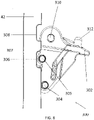
- the locking mechanism 300 includes a holder 302 which further includes a plurality of components that are designed to work in tandem with the drive blade's shaft portion 301 so as to provide a locking function for preventing accidental actuation of the fastener driver 10.
- the holder 302 pivots about an axle 310, which is configured in a fixed portion near the front end of the fastener driver 10,
- the holder 302 is further connected with the same fixed portion by a resiliently deformable member 314 that is disposed between the fixed portion and a finger 312 on the holder 302.
- a spring 314 is used for providing a biasing force so as to urge the holder in a first direction.
- the holder 302 may include a plurality of locking members and in this embodiment, the holder 302 includes two locking members 304, 305 in the form of a pin, which are designed to interact with catches formed on the drive blade's shaft portion 301.
- the holder 302 also has a tab portion 318 for being engaged with a trip portion 316 from the reciprocating piston 58 for urging the holder 302 into a second direction.
- the locking mechanism 300 relies on the automatic engagement between the pins 304, 305 on the holder 302 and the catches 306, 308 which are integrally formed on the drive blade 42.
- the pins 304, 305 may have circular cross sections or in some instances ellipsoidal cross sections.
- the pins 304, 305 are made of a high strength material or preferably an alloy that has high resistance to impact loading and fatigue. Also, the material used should also have high ductility so as to allow the user some leeway for noticing the conditions of the pins 304, 305 from the positioning of the drive blade 42 in the initial position. Brittle materials should be avoided as snapping of the pins 304, 305 would allow fasteners to be driven accidentally and thus becoming a hazard to the user.
- the pins 304, 305 are designed to engage with the catches that are integrally formed on the drive blade 42.
- the catches in this embodiment are two notches formed serially along the drive blade's longitudinal direction.
- the two notches is consisting of a first notch 306 and a second notch 308.
- the first notch 306 is different to the second notch 308 in a way that the first notch includes a slanted edge, which is a ramp 307 in this embodiment as shown in Fig.3 .
- the second notch 308 only has a symmetrically formed profile.
- the two notches are spaced apart from each other and the ramp 307 forms a smooth transition between the first notch 306 and the second notch 308.
- Fig.4 shows the locking mechanism 300 in a locking position whilst the drive blade 42 is in an initial position.
- the holder 302 is urged by a spring (not shown) and the result is that the two pins 304, 305 are fully engaged with the first and second notches 306, 308.
- the longitudinal movement of the drive blade 42 along its longitudinal axis is fully restricted by the locking mechanism 300 so that maximum safety is ensured.
- each pin 304,305 is engaged with a respective notch and the pins 304, 305 are urged by the spring (not shown) through the holder 302 toward a locking position for restricting the movement of the drive blade 42.
- a user actuates the trigger (not shown) of the fastener driver for powering of the motor. Actuation of the trigger will cause the reciprocating piston to move toward the holder and allowing the trip portion on the reciprocating piston to engage the tab portion 318 on the holder 302.
- the holder 302 will be urged to a first direction, which in this embodiment is the anti-clockwise direction. The movement of the holder 302 will also cause the at least two locking members moving away from the at least two catches and therefore derestricting the movement of the drive blade 42.
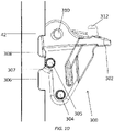
- Fig.7 shows a drive blade 42 to be in its driving position for driving a fastener. As the figure shown, the at least two catches are well beyond the at least two locking members on the holder 302.
- the reciprocating piston will move in the direction of the drive blade's initial position and therefore causing the trip portion on the reciprocating piston to disengage from the tab portion 318 of the holder 302.
- Such disengagement will also rid of any biasing force acted on the tab portion 318 of the holder 302.
- the holder 302 in this embodiment will be urged in a second direction, which is the clockwise direction so as to move the at least two locking members in the direction of the drive blade 42.
- the first locking member 305 will be caught by the first catch 306 as shown in Fig.8 during the return of the drive blade 42 toward its initial position.
- the locking member being caught by the first catch 306 will then be slid out of the first catch 306 along a ramp 307 that is formed between the first catch 306 and the second catch 308. The locking member will then slide towards to the second catch 308 as the drive blade continues returning to its initial position.
- both of the locking members 304 engage with a respective first and second catch 306,308 and completing the locking function of the locking mechanism 300.
- the two locking members 304,305 are both being urged toward the longitudinal edge of the catches 306,308 to ensure that the drive blade 42 would be securely restricted for preventing any accidental movement.
- another fastener driver may have a locking mechanism that includes more than two locking members and more than two catches.
- the locking members and the catches will be similarly formed as the embodiment in Figs.3-11 as in the locking members will also be pins that have either a circular cross-section profile or an ellipsoidal cross-section profile.
- the catches would also be integrally formed on the drive blade except that there will be at least two ramps being formed should there be three catches.
Landscapes
- Engineering & Computer Science (AREA)
- Mechanical Engineering (AREA)
- Physics & Mathematics (AREA)
- Fluid Mechanics (AREA)
- Portable Nailing Machines And Staplers (AREA)
Claims (15)
- Outil électrique (10) d'entraînement d'une fixation incluant :un cylindre (50) ;un piston d'entraînement (54) au sein du cylindre, le piston d'entraînement soumis à une force d'entraînement résultant d'une différence de pression, le piston d'entraînement déplaçable entre une position initiale et une position d'entraînement ;une pale d'entraînement (42) couplée au piston d'entraînement et pouvant fonctionner pour entraîner une fixation ;dans lequel l'outil électrique comprend un mécanisme de verrouillage (300) qui fonctionne par engagement entre au moins deux ergots (306, 308) et au moins deux éléments de verrouillage (304, 305), caractérisé en ce que les au moins deux ergots sont formés en série sur la pale d'entraînement le long de la direction longitudinale de la pale d'entraînement.
- Outil électrique (10) selon la revendication 1, dans lequel les au moins deux ergots (306, 308) sont au moins deux encoches (306, 308) qui sont solidairement formées sur la pale d'entraînement (42),et éventuellement dans lequel l'une des au moins deux encoches comprend une rampe (307),et en outre éventuellement dans lequel les au moins deux encoches sont formées sur un côté de la pale d'entraînement.
- Outil électrique (10) selon la revendication 1, dans lequel les au moins deux éléments de verrouillage (304, 305) sont au moins deux goupilles (304, 305) qui sont montées avec un support (302) qui est séparé de la pale d'entraînement (42),et éventuellement dans lequel les goupilles ont une section transversale circulaire ou ellipsoïdale,et/ou dans lequel l'engagement entre les au moins deux goupilles et les au moins deux encoches dépendent de l'emplacement du support.
- Outil électrique (10) selon la revendication 3,dans lequel le support (302) est sollicité par un élément élastiquement déformable, qui est monté entre une partie de languette (318) du support et une partie structurelle de l'outil électrique,
oudans lequel le support peut pivoter entre une position de verrouillage et une position de déverrouillage,
oudans lequel le support pivote dans une première direction telle que les au moins deux goupilles (304, 305) s'éloignent des au moins deux encoches (306, 308) lorsque la languette du support est pressée par un élément de déclenchement (316). - Outil électrique (10) selon la revendication 3, dans lequel le support (302) pivote dans une seconde direction telle que les au moins deux goupilles (304, 305) se rapprochent des au moins deux encoches (306, 308) lorsque la languette du support (318) est séparée de l'élément de déclenchement (316),
et éventuellementdans lequel les au moins deux goupilles se désengagent des au moins deux encoches lorsque le support pivote dans la première direction,
oudans lequel les au moins deux goupilles tentent de s'engager dans les au moins deux encoches lorsque le support pivote dans la seconde direction,et éventuellement dans lequel une première des au moins deux goupilles s'engagera dans les au moins deux encoches et la seconde des au moins deux goupilles ne s'engagera que dans l'une des au moins deux encoches. - Procédé d'engagement d'un mécanisme de verrouillage (300), incluant :la poussée d'une pale d'entraînement (42) verrouillée par un mécanisme de verrouillage vers une position d'entraînement (54) de manière à entraîner une fixation ;la poussée d'un support (302) vers une première direction et caractérisé parle déplacement d'au moins deux éléments de verrouillage (304, 305) à l'écart d'au moins deux ergots (306, 308) pour désengager le mécanisme de verrouillage de sorte que la pale d'entraînement peut fonctionner pour entraîner une fixation, les au moins deux ergots formés en série sur la pale d'entraînement le long de la direction longitudinale de la pale d'entraînement.
- Procédé d'engagement du mécanisme de verrouillage (300) selon la revendication 6,dans lequel les au moins deux éléments de verrouillage (304, 305) sont au moins deux goupilles (304, 305) qui sont montées avec un support (302) qui est séparé de la pale d'entraînement (42),
oudans lequel les au moins deux ergots (306, 308) sont au moins deux encoches (306, 308) qui sont solidairement formées sur la pale d'entraînement, et éventuellement dans lequel l'une des au moins deux encoches inclut une rampe (307). - Procédé d'engagement du mécanisme de verrouillage (300) selon la revendication 6, dans lequel les goupilles (304, 305) ont une section transversale circulaire ou ellipsoïdale.
- Procédé d'engagement d'un mécanisme de verrouillage (300), incluant :la poussée d'une pale d'entraînement (42) vers une position initiale de manière à s'engager dans un mécanisme de verrouillage ;la poussée d'un support (302) vers une seconde direction ;le déplacement des au moins deux éléments de verrouillage (304, 305) plus près des au moins deux ergots (306, 308) de sorte que pendant la course de retour de la pale d'entraînement, au moins l'un des éléments de verrouillage est en contact avec l'un des au moins deux ergots sur la pale d'entraînement et caractérisé parle positionnement des au moins deux éléments de verrouillage avec un ergot respectif pour s'engager dans le mécanisme de verrouillage, les au moins deux ergots formés en série sur la pale d'entraînement le long de la direction longitudinale de la pale d'entraînement.
- Procédé d'engagement du mécanisme de verrouillage (300) selon la revendication 9, dans lequel les au moins deux éléments de verrouillage (304, 305) sont au moins deux goupilles (304, 305) qui sont montées avec un support (302) qui est séparé de la pale d'entraînement (42).
- Procédé d'engagement du mécanisme de verrouillage (300) selon la revendication 9, dans lequel les au moins deux ergots (306, 308) sont au moins deux encoches (306, 308) qui sont solidairement formées sur la pale d'entraînement (42).
- Procédé d'engagement du mécanisme de verrouillage (300) selon la revendication 11, dans lequel l'une des au moins deux encoches (306, 308) inclut une rampe (307).
- Procédé d'engagement du mécanisme de verrouillage (300) selon la revendication 9, dans lequel les goupilles (304, 305) ont une section transversale circulaire ou ellipsoïdale.
- Procédé d'engagement du mécanisme de verrouillage (300) selon les revendications 6 ou 9, dans lequel le procédé inclut la modification de la position du support de manière à commander un engagement entre les goupilles (304, 305) et les encoches (306, 308).
- Procédé d'engagement du mécanisme de verrouillage (300) selon la revendication 12, comprenant en outre :l'engagement d'au moins deux éléments de verrouillage (304, 305) dans un ergot respectif de manière à verrouiller la pale d'entraînement pour empêcher un déplacement accidentel de la pale d'entraînement (42) ;l'engagement d'un premier élément de verrouillage dans une première encoche puis le retrait du premier élément de verrouillage de la première encoche de la rampe (307) ; etl'engagement du premier élément de verrouillage dans une seconde encoche tout en engageant un second élément de verrouillage dans la première encoche de manière à terminer l'engagement du mécanisme de verrouillage.
Applications Claiming Priority (1)
| Application Number | Priority Date | Filing Date | Title |
|---|---|---|---|
| PCT/CN2015/071302 WO2016115705A1 (fr) | 2015-01-22 | 2015-01-22 | Outils électriques contenant des mécanismes de verrouillage et procédé de mise en prise de tels mécanismes de verrouillage |
Publications (3)
| Publication Number | Publication Date |
|---|---|
| EP3247538A1 EP3247538A1 (fr) | 2017-11-29 |
| EP3247538A4 EP3247538A4 (fr) | 2018-10-10 |
| EP3247538B1 true EP3247538B1 (fr) | 2022-03-30 |
Family
ID=56416289
Family Applications (1)
| Application Number | Title | Priority Date | Filing Date |
|---|---|---|---|
| EP15878382.9A Active EP3247538B1 (fr) | 2015-01-22 | 2015-01-22 | Outils électriques contenant des mécanismes de verrouillage et procédé de mise en prise de tels mécanismes de verrouillage |
Country Status (4)
| Country | Link |
|---|---|
| EP (1) | EP3247538B1 (fr) |
| CN (1) | CN107206580A (fr) |
| AU (1) | AU2015378403B2 (fr) |
| WO (1) | WO2016115705A1 (fr) |
Families Citing this family (5)
| Publication number | Priority date | Publication date | Assignee | Title |
|---|---|---|---|---|
| CN110757413B (zh) | 2018-07-26 | 2022-08-26 | 创科无线普通合伙 | 气动工具 |
| CN208614700U (zh) * | 2018-08-25 | 2019-03-19 | 张华定 | 一种可调打钉枪 |
| CN110900524B (zh) * | 2018-09-18 | 2023-07-14 | 苏州宝时得电动工具有限公司 | 钉枪、钉枪的控制系统及启停控制方法 |
| USD900575S1 (en) | 2018-09-26 | 2020-11-03 | Milwaukee Electric Tool Corporation | Powered fastener driver |
| CN109605285B (zh) | 2019-01-31 | 2024-03-19 | 台州市钉霸电动工具有限公司 | 一种打钉枪 |
Family Cites Families (7)
| Publication number | Priority date | Publication date | Assignee | Title |
|---|---|---|---|---|
| US6609646B2 (en) * | 2001-02-08 | 2003-08-26 | Black & Decker Inc. | Magazine assembly for fastening tool |
| US6929165B1 (en) * | 2004-08-04 | 2005-08-16 | Rexon Industrial Corp., Ltd. | Pneumatic nail gun |
| US8800835B2 (en) * | 2008-07-17 | 2014-08-12 | Stanley Fastening Systems, Lp | Fastener driving device with mode selector and trigger interlock |
| US8833626B2 (en) * | 2010-09-29 | 2014-09-16 | Stanley Fastening Systems, L.P. | Fastening tool |
| US20140014703A1 (en) * | 2012-07-10 | 2014-01-16 | Illinois Tool Works Inc. | Fastener driving tool with fastener driving and rotating mechanism |
| CN203156697U (zh) * | 2012-12-21 | 2013-08-28 | 亿得隆塑料五金制品(嘉兴)有限公司 | 具有安全装置的钉枪 |
| US9636811B2 (en) * | 2013-03-11 | 2017-05-02 | Illinois Tool Works Inc. | Actuation lockout for a fastener-driving tool |
-
2015
- 2015-01-22 WO PCT/CN2015/071302 patent/WO2016115705A1/fr active Application Filing
- 2015-01-22 CN CN201580073881.2A patent/CN107206580A/zh active Pending
- 2015-01-22 AU AU2015378403A patent/AU2015378403B2/en active Active
- 2015-01-22 EP EP15878382.9A patent/EP3247538B1/fr active Active
Also Published As
| Publication number | Publication date |
|---|---|
| AU2015378403A1 (en) | 2017-08-03 |
| AU2015378403B2 (en) | 2018-12-06 |
| EP3247538A4 (fr) | 2018-10-10 |
| EP3247538A1 (fr) | 2017-11-29 |
| CN107206580A (zh) | 2017-09-26 |
| WO2016115705A1 (fr) | 2016-07-28 |
Similar Documents
| Publication | Publication Date | Title |
|---|---|---|
| EP3247538B1 (fr) | Outils électriques contenant des mécanismes de verrouillage et procédé de mise en prise de tels mécanismes de verrouillage | |
| EP2716409B1 (fr) | Système d'activation doté d'un bras multi-angles et mécanisme de libération de blocage | |
| US8292143B2 (en) | Dry fire lockout with bypass for fastener driving device | |
| US10562163B2 (en) | Driving tool | |
| EP2669058A2 (fr) | Outil électrique ayant un actionneur de déclenchement à ressort | |
| EP3131708B1 (fr) | Outil d'enfoncement de dispositif de fixation comprenant un dispositif d'entraînement | |
| EP3321038B1 (fr) | Dispositif d'entraînement de fixation de ressort à gaz | |
| CN110253503B (zh) | 一种紧固件击打工具 | |
| US9186788B2 (en) | Lockout mechanism | |
| EP3689550A2 (fr) | Dispositif d'entraînement de fixation motorisé | |
| EP4223455A2 (fr) | Mécanisme anti-recul | |
| US20130186663A1 (en) | Multi-tool for fasteners | |
| CN113165150B (zh) | 打入工具 | |
| TWI630990B (zh) | 具有可卸除工件接觸單元之緊固工具 | |
| US8757032B2 (en) | Shifting device for a wrench tool | |
| US10828761B2 (en) | Powered fastener driving tool | |
| US11491623B2 (en) | Fastener driving tool | |
| US20150041517A1 (en) | Fastener feeding device for a driving tool | |
| WO2007007717A1 (fr) | Outil enfonceur |
Legal Events
| Date | Code | Title | Description |
|---|---|---|---|
| STAA | Information on the status of an ep patent application or granted ep patent |
Free format text: STATUS: THE INTERNATIONAL PUBLICATION HAS BEEN MADE |
|
| PUAI | Public reference made under article 153(3) epc to a published international application that has entered the european phase |
Free format text: ORIGINAL CODE: 0009012 |
|
| STAA | Information on the status of an ep patent application or granted ep patent |
Free format text: STATUS: REQUEST FOR EXAMINATION WAS MADE |
|
| 17P | Request for examination filed |
Effective date: 20170721 |
|
| AK | Designated contracting states |
Kind code of ref document: A1 Designated state(s): AL AT BE BG CH CY CZ DE DK EE ES FI FR GB GR HR HU IE IS IT LI LT LU LV MC MK MT NL NO PL PT RO RS SE SI SK SM TR |
|
| AX | Request for extension of the european patent |
Extension state: BA ME |
|
| DAX | Request for extension of the european patent (deleted) | ||
| A4 | Supplementary search report drawn up and despatched |
Effective date: 20180906 |
|
| RIC1 | Information provided on ipc code assigned before grant |
Ipc: B25C 1/04 20060101AFI20180901BHEP Ipc: B25C 5/00 20060101ALI20180901BHEP |
|
| REG | Reference to a national code |
Ref country code: DE Ref legal event code: R079 Ref document number: 602015077946 Country of ref document: DE Free format text: PREVIOUS MAIN CLASS: B25C0001040000 Ipc: B25C0001000000 |
|
| RIC1 | Information provided on ipc code assigned before grant |
Ipc: B25C 1/00 20060101AFI20211004BHEP |
|
| GRAP | Despatch of communication of intention to grant a patent |
Free format text: ORIGINAL CODE: EPIDOSNIGR1 |
|
| STAA | Information on the status of an ep patent application or granted ep patent |
Free format text: STATUS: GRANT OF PATENT IS INTENDED |
|
| INTG | Intention to grant announced |
Effective date: 20211112 |
|
| GRAS | Grant fee paid |
Free format text: ORIGINAL CODE: EPIDOSNIGR3 |
|
| GRAA | (expected) grant |
Free format text: ORIGINAL CODE: 0009210 |
|
| STAA | Information on the status of an ep patent application or granted ep patent |
Free format text: STATUS: THE PATENT HAS BEEN GRANTED |
|
| AK | Designated contracting states |
Kind code of ref document: B1 Designated state(s): AL AT BE BG CH CY CZ DE DK EE ES FI FR GB GR HR HU IE IS IT LI LT LU LV MC MK MT NL NO PL PT RO RS SE SI SK SM TR |
|
| REG | Reference to a national code |
Ref country code: GB Ref legal event code: FG4D |
|
| REG | Reference to a national code |
Ref country code: CH Ref legal event code: EP |
|
| REG | Reference to a national code |
Ref country code: DE Ref legal event code: R096 Ref document number: 602015077946 Country of ref document: DE |
|
| REG | Reference to a national code |
Ref country code: AT Ref legal event code: REF Ref document number: 1478738 Country of ref document: AT Kind code of ref document: T Effective date: 20220415 |
|
| REG | Reference to a national code |
Ref country code: IE Ref legal event code: FG4D |
|
| REG | Reference to a national code |
Ref country code: LT Ref legal event code: MG9D |
|
| PG25 | Lapsed in a contracting state [announced via postgrant information from national office to epo] |
Ref country code: SE Free format text: LAPSE BECAUSE OF FAILURE TO SUBMIT A TRANSLATION OF THE DESCRIPTION OR TO PAY THE FEE WITHIN THE PRESCRIBED TIME-LIMIT Effective date: 20220330 Ref country code: RS Free format text: LAPSE BECAUSE OF FAILURE TO SUBMIT A TRANSLATION OF THE DESCRIPTION OR TO PAY THE FEE WITHIN THE PRESCRIBED TIME-LIMIT Effective date: 20220330 Ref country code: NO Free format text: LAPSE BECAUSE OF FAILURE TO SUBMIT A TRANSLATION OF THE DESCRIPTION OR TO PAY THE FEE WITHIN THE PRESCRIBED TIME-LIMIT Effective date: 20220630 Ref country code: LT Free format text: LAPSE BECAUSE OF FAILURE TO SUBMIT A TRANSLATION OF THE DESCRIPTION OR TO PAY THE FEE WITHIN THE PRESCRIBED TIME-LIMIT Effective date: 20220330 Ref country code: HR Free format text: LAPSE BECAUSE OF FAILURE TO SUBMIT A TRANSLATION OF THE DESCRIPTION OR TO PAY THE FEE WITHIN THE PRESCRIBED TIME-LIMIT Effective date: 20220330 Ref country code: BG Free format text: LAPSE BECAUSE OF FAILURE TO SUBMIT A TRANSLATION OF THE DESCRIPTION OR TO PAY THE FEE WITHIN THE PRESCRIBED TIME-LIMIT Effective date: 20220630 |
|
| REG | Reference to a national code |
Ref country code: NL Ref legal event code: MP Effective date: 20220330 |
|
| REG | Reference to a national code |
Ref country code: AT Ref legal event code: MK05 Ref document number: 1478738 Country of ref document: AT Kind code of ref document: T Effective date: 20220330 |
|
| PG25 | Lapsed in a contracting state [announced via postgrant information from national office to epo] |
Ref country code: LV Free format text: LAPSE BECAUSE OF FAILURE TO SUBMIT A TRANSLATION OF THE DESCRIPTION OR TO PAY THE FEE WITHIN THE PRESCRIBED TIME-LIMIT Effective date: 20220330 Ref country code: GR Free format text: LAPSE BECAUSE OF FAILURE TO SUBMIT A TRANSLATION OF THE DESCRIPTION OR TO PAY THE FEE WITHIN THE PRESCRIBED TIME-LIMIT Effective date: 20220701 Ref country code: FI Free format text: LAPSE BECAUSE OF FAILURE TO SUBMIT A TRANSLATION OF THE DESCRIPTION OR TO PAY THE FEE WITHIN THE PRESCRIBED TIME-LIMIT Effective date: 20220330 |
|
| PG25 | Lapsed in a contracting state [announced via postgrant information from national office to epo] |
Ref country code: NL Free format text: LAPSE BECAUSE OF FAILURE TO SUBMIT A TRANSLATION OF THE DESCRIPTION OR TO PAY THE FEE WITHIN THE PRESCRIBED TIME-LIMIT Effective date: 20220330 |
|
| PG25 | Lapsed in a contracting state [announced via postgrant information from national office to epo] |
Ref country code: SM Free format text: LAPSE BECAUSE OF FAILURE TO SUBMIT A TRANSLATION OF THE DESCRIPTION OR TO PAY THE FEE WITHIN THE PRESCRIBED TIME-LIMIT Effective date: 20220330 Ref country code: SK Free format text: LAPSE BECAUSE OF FAILURE TO SUBMIT A TRANSLATION OF THE DESCRIPTION OR TO PAY THE FEE WITHIN THE PRESCRIBED TIME-LIMIT Effective date: 20220330 Ref country code: RO Free format text: LAPSE BECAUSE OF FAILURE TO SUBMIT A TRANSLATION OF THE DESCRIPTION OR TO PAY THE FEE WITHIN THE PRESCRIBED TIME-LIMIT Effective date: 20220330 Ref country code: PT Free format text: LAPSE BECAUSE OF FAILURE TO SUBMIT A TRANSLATION OF THE DESCRIPTION OR TO PAY THE FEE WITHIN THE PRESCRIBED TIME-LIMIT Effective date: 20220801 Ref country code: ES Free format text: LAPSE BECAUSE OF FAILURE TO SUBMIT A TRANSLATION OF THE DESCRIPTION OR TO PAY THE FEE WITHIN THE PRESCRIBED TIME-LIMIT Effective date: 20220330 Ref country code: EE Free format text: LAPSE BECAUSE OF FAILURE TO SUBMIT A TRANSLATION OF THE DESCRIPTION OR TO PAY THE FEE WITHIN THE PRESCRIBED TIME-LIMIT Effective date: 20220330 Ref country code: CZ Free format text: LAPSE BECAUSE OF FAILURE TO SUBMIT A TRANSLATION OF THE DESCRIPTION OR TO PAY THE FEE WITHIN THE PRESCRIBED TIME-LIMIT Effective date: 20220330 Ref country code: AT Free format text: LAPSE BECAUSE OF FAILURE TO SUBMIT A TRANSLATION OF THE DESCRIPTION OR TO PAY THE FEE WITHIN THE PRESCRIBED TIME-LIMIT Effective date: 20220330 |
|
| PG25 | Lapsed in a contracting state [announced via postgrant information from national office to epo] |
Ref country code: PL Free format text: LAPSE BECAUSE OF FAILURE TO SUBMIT A TRANSLATION OF THE DESCRIPTION OR TO PAY THE FEE WITHIN THE PRESCRIBED TIME-LIMIT Effective date: 20220330 Ref country code: IS Free format text: LAPSE BECAUSE OF FAILURE TO SUBMIT A TRANSLATION OF THE DESCRIPTION OR TO PAY THE FEE WITHIN THE PRESCRIBED TIME-LIMIT Effective date: 20220730 Ref country code: AL Free format text: LAPSE BECAUSE OF FAILURE TO SUBMIT A TRANSLATION OF THE DESCRIPTION OR TO PAY THE FEE WITHIN THE PRESCRIBED TIME-LIMIT Effective date: 20220330 |
|
| REG | Reference to a national code |
Ref country code: DE Ref legal event code: R097 Ref document number: 602015077946 Country of ref document: DE |
|
| PG25 | Lapsed in a contracting state [announced via postgrant information from national office to epo] |
Ref country code: DK Free format text: LAPSE BECAUSE OF FAILURE TO SUBMIT A TRANSLATION OF THE DESCRIPTION OR TO PAY THE FEE WITHIN THE PRESCRIBED TIME-LIMIT Effective date: 20220330 |
|
| PLBE | No opposition filed within time limit |
Free format text: ORIGINAL CODE: 0009261 |
|
| STAA | Information on the status of an ep patent application or granted ep patent |
Free format text: STATUS: NO OPPOSITION FILED WITHIN TIME LIMIT |
|
| 26N | No opposition filed |
Effective date: 20230103 |
|
| PGFP | Annual fee paid to national office [announced via postgrant information from national office to epo] |
Ref country code: FR Payment date: 20230125 Year of fee payment: 9 |
|
| PG25 | Lapsed in a contracting state [announced via postgrant information from national office to epo] |
Ref country code: SI Free format text: LAPSE BECAUSE OF FAILURE TO SUBMIT A TRANSLATION OF THE DESCRIPTION OR TO PAY THE FEE WITHIN THE PRESCRIBED TIME-LIMIT Effective date: 20220330 |
|
| PG25 | Lapsed in a contracting state [announced via postgrant information from national office to epo] |
Ref country code: IT Free format text: LAPSE BECAUSE OF FAILURE TO SUBMIT A TRANSLATION OF THE DESCRIPTION OR TO PAY THE FEE WITHIN THE PRESCRIBED TIME-LIMIT Effective date: 20220330 |
|
| REG | Reference to a national code |
Ref country code: CH Ref legal event code: PL |
|
| PG25 | Lapsed in a contracting state [announced via postgrant information from national office to epo] |
Ref country code: LU Free format text: LAPSE BECAUSE OF NON-PAYMENT OF DUE FEES Effective date: 20230122 |
|
| REG | Reference to a national code |
Ref country code: BE Ref legal event code: MM Effective date: 20230131 |
|
| PG25 | Lapsed in a contracting state [announced via postgrant information from national office to epo] |
Ref country code: LI Free format text: LAPSE BECAUSE OF NON-PAYMENT OF DUE FEES Effective date: 20230131 Ref country code: CH Free format text: LAPSE BECAUSE OF NON-PAYMENT OF DUE FEES Effective date: 20230131 |
|
| PG25 | Lapsed in a contracting state [announced via postgrant information from national office to epo] |
Ref country code: BE Free format text: LAPSE BECAUSE OF NON-PAYMENT OF DUE FEES Effective date: 20230131 |
|
| PG25 | Lapsed in a contracting state [announced via postgrant information from national office to epo] |
Ref country code: IE Free format text: LAPSE BECAUSE OF NON-PAYMENT OF DUE FEES Effective date: 20230122 |
|
| PGFP | Annual fee paid to national office [announced via postgrant information from national office to epo] |
Ref country code: DE Payment date: 20240129 Year of fee payment: 10 Ref country code: GB Payment date: 20240129 Year of fee payment: 10 |