EP3247437B1 - Beatmungsgerät mit verbesserter synchronität beim übergang von exspiratorischem zu inspiratorischem betrieb - Google Patents
Beatmungsgerät mit verbesserter synchronität beim übergang von exspiratorischem zu inspiratorischem betrieb Download PDFInfo
- Publication number
- EP3247437B1 EP3247437B1 EP17716248.4A EP17716248A EP3247437B1 EP 3247437 B1 EP3247437 B1 EP 3247437B1 EP 17716248 A EP17716248 A EP 17716248A EP 3247437 B1 EP3247437 B1 EP 3247437B1
- Authority
- EP
- European Patent Office
- Prior art keywords
- expiratory
- ventilator
- time constant
- flow
- control device
- Prior art date
- Legal status (The legal status is an assumption and is not a legal conclusion. Google has not performed a legal analysis and makes no representation as to the accuracy of the status listed.)
- Active
Links
Images

Classifications
-
- A—HUMAN NECESSITIES
- A61—MEDICAL OR VETERINARY SCIENCE; HYGIENE
- A61M—DEVICES FOR INTRODUCING MEDIA INTO, OR ONTO, THE BODY; DEVICES FOR TRANSDUCING BODY MEDIA OR FOR TAKING MEDIA FROM THE BODY; DEVICES FOR PRODUCING OR ENDING SLEEP OR STUPOR
- A61M16/00—Devices for influencing the respiratory system of patients by gas treatment, e.g. ventilators; Tracheal tubes
- A61M16/021—Devices for influencing the respiratory system of patients by gas treatment, e.g. ventilators; Tracheal tubes operated by electrical means
- A61M16/022—Control means therefor
- A61M16/024—Control means therefor including calculation means, e.g. using a processor
- A61M16/026—Control means therefor including calculation means, e.g. using a processor specially adapted for predicting, e.g. for determining an information representative of a flow limitation during a ventilation cycle by using a root square technique or a regression analysis
-
- A—HUMAN NECESSITIES
- A61—MEDICAL OR VETERINARY SCIENCE; HYGIENE
- A61M—DEVICES FOR INTRODUCING MEDIA INTO, OR ONTO, THE BODY; DEVICES FOR TRANSDUCING BODY MEDIA OR FOR TAKING MEDIA FROM THE BODY; DEVICES FOR PRODUCING OR ENDING SLEEP OR STUPOR
- A61M16/00—Devices for influencing the respiratory system of patients by gas treatment, e.g. ventilators; Tracheal tubes
- A61M16/0003—Accessories therefor, e.g. sensors, vibrators, negative pressure
-
- A—HUMAN NECESSITIES
- A61—MEDICAL OR VETERINARY SCIENCE; HYGIENE
- A61M—DEVICES FOR INTRODUCING MEDIA INTO, OR ONTO, THE BODY; DEVICES FOR TRANSDUCING BODY MEDIA OR FOR TAKING MEDIA FROM THE BODY; DEVICES FOR PRODUCING OR ENDING SLEEP OR STUPOR
- A61M16/00—Devices for influencing the respiratory system of patients by gas treatment, e.g. ventilators; Tracheal tubes
- A61M16/10—Preparation of respiratory gases or vapours
- A61M16/104—Preparation of respiratory gases or vapours specially adapted for anaesthetics
-
- A—HUMAN NECESSITIES
- A61—MEDICAL OR VETERINARY SCIENCE; HYGIENE
- A61M—DEVICES FOR INTRODUCING MEDIA INTO, OR ONTO, THE BODY; DEVICES FOR TRANSDUCING BODY MEDIA OR FOR TAKING MEDIA FROM THE BODY; DEVICES FOR PRODUCING OR ENDING SLEEP OR STUPOR
- A61M16/00—Devices for influencing the respiratory system of patients by gas treatment, e.g. ventilators; Tracheal tubes
- A61M16/20—Valves specially adapted to medical respiratory devices
- A61M16/208—Non-controlled one-way valves, e.g. exhalation, check, pop-off non-rebreathing valves
-
- A—HUMAN NECESSITIES
- A61—MEDICAL OR VETERINARY SCIENCE; HYGIENE
- A61B—DIAGNOSIS; SURGERY; IDENTIFICATION
- A61B5/00—Measuring for diagnostic purposes; Identification of persons
- A61B5/08—Measuring devices for evaluating the respiratory organs
- A61B5/087—Measuring breath flow
-
- A—HUMAN NECESSITIES
- A61—MEDICAL OR VETERINARY SCIENCE; HYGIENE
- A61M—DEVICES FOR INTRODUCING MEDIA INTO, OR ONTO, THE BODY; DEVICES FOR TRANSDUCING BODY MEDIA OR FOR TAKING MEDIA FROM THE BODY; DEVICES FOR PRODUCING OR ENDING SLEEP OR STUPOR
- A61M16/00—Devices for influencing the respiratory system of patients by gas treatment, e.g. ventilators; Tracheal tubes
- A61M16/01—Devices for influencing the respiratory system of patients by gas treatment, e.g. ventilators; Tracheal tubes specially adapted for anaesthetising
-
- A—HUMAN NECESSITIES
- A61—MEDICAL OR VETERINARY SCIENCE; HYGIENE
- A61M—DEVICES FOR INTRODUCING MEDIA INTO, OR ONTO, THE BODY; DEVICES FOR TRANSDUCING BODY MEDIA OR FOR TAKING MEDIA FROM THE BODY; DEVICES FOR PRODUCING OR ENDING SLEEP OR STUPOR
- A61M16/00—Devices for influencing the respiratory system of patients by gas treatment, e.g. ventilators; Tracheal tubes
- A61M16/10—Preparation of respiratory gases or vapours
- A61M16/14—Preparation of respiratory gases or vapours by mixing different fluids, one of them being in a liquid phase
- A61M16/16—Devices to humidify the respiration air
-
- A—HUMAN NECESSITIES
- A61—MEDICAL OR VETERINARY SCIENCE; HYGIENE
- A61M—DEVICES FOR INTRODUCING MEDIA INTO, OR ONTO, THE BODY; DEVICES FOR TRANSDUCING BODY MEDIA OR FOR TAKING MEDIA FROM THE BODY; DEVICES FOR PRODUCING OR ENDING SLEEP OR STUPOR
- A61M16/00—Devices for influencing the respiratory system of patients by gas treatment, e.g. ventilators; Tracheal tubes
- A61M16/20—Valves specially adapted to medical respiratory devices
- A61M16/201—Controlled valves
- A61M16/202—Controlled valves electrically actuated
- A61M16/203—Proportional
- A61M16/204—Proportional used for inhalation control
-
- A—HUMAN NECESSITIES
- A61—MEDICAL OR VETERINARY SCIENCE; HYGIENE
- A61M—DEVICES FOR INTRODUCING MEDIA INTO, OR ONTO, THE BODY; DEVICES FOR TRANSDUCING BODY MEDIA OR FOR TAKING MEDIA FROM THE BODY; DEVICES FOR PRODUCING OR ENDING SLEEP OR STUPOR
- A61M16/00—Devices for influencing the respiratory system of patients by gas treatment, e.g. ventilators; Tracheal tubes
- A61M16/20—Valves specially adapted to medical respiratory devices
- A61M16/201—Controlled valves
- A61M16/202—Controlled valves electrically actuated
- A61M16/203—Proportional
- A61M16/205—Proportional used for exhalation control
-
- A—HUMAN NECESSITIES
- A61—MEDICAL OR VETERINARY SCIENCE; HYGIENE
- A61M—DEVICES FOR INTRODUCING MEDIA INTO, OR ONTO, THE BODY; DEVICES FOR TRANSDUCING BODY MEDIA OR FOR TAKING MEDIA FROM THE BODY; DEVICES FOR PRODUCING OR ENDING SLEEP OR STUPOR
- A61M16/00—Devices for influencing the respiratory system of patients by gas treatment, e.g. ventilators; Tracheal tubes
- A61M16/0003—Accessories therefor, e.g. sensors, vibrators, negative pressure
- A61M2016/0015—Accessories therefor, e.g. sensors, vibrators, negative pressure inhalation detectors
- A61M2016/0018—Accessories therefor, e.g. sensors, vibrators, negative pressure inhalation detectors electrical
-
- A—HUMAN NECESSITIES
- A61—MEDICAL OR VETERINARY SCIENCE; HYGIENE
- A61M—DEVICES FOR INTRODUCING MEDIA INTO, OR ONTO, THE BODY; DEVICES FOR TRANSDUCING BODY MEDIA OR FOR TAKING MEDIA FROM THE BODY; DEVICES FOR PRODUCING OR ENDING SLEEP OR STUPOR
- A61M16/00—Devices for influencing the respiratory system of patients by gas treatment, e.g. ventilators; Tracheal tubes
- A61M16/0003—Accessories therefor, e.g. sensors, vibrators, negative pressure
- A61M2016/0027—Accessories therefor, e.g. sensors, vibrators, negative pressure pressure meter
-
- A—HUMAN NECESSITIES
- A61—MEDICAL OR VETERINARY SCIENCE; HYGIENE
- A61M—DEVICES FOR INTRODUCING MEDIA INTO, OR ONTO, THE BODY; DEVICES FOR TRANSDUCING BODY MEDIA OR FOR TAKING MEDIA FROM THE BODY; DEVICES FOR PRODUCING OR ENDING SLEEP OR STUPOR
- A61M16/00—Devices for influencing the respiratory system of patients by gas treatment, e.g. ventilators; Tracheal tubes
- A61M16/0003—Accessories therefor, e.g. sensors, vibrators, negative pressure
- A61M2016/003—Accessories therefor, e.g. sensors, vibrators, negative pressure with a flowmeter
- A61M2016/0033—Accessories therefor, e.g. sensors, vibrators, negative pressure with a flowmeter electrical
- A61M2016/0036—Accessories therefor, e.g. sensors, vibrators, negative pressure with a flowmeter electrical in the breathing tube and used in both inspiratory and expiratory phase
-
- A—HUMAN NECESSITIES
- A61—MEDICAL OR VETERINARY SCIENCE; HYGIENE
- A61M—DEVICES FOR INTRODUCING MEDIA INTO, OR ONTO, THE BODY; DEVICES FOR TRANSDUCING BODY MEDIA OR FOR TAKING MEDIA FROM THE BODY; DEVICES FOR PRODUCING OR ENDING SLEEP OR STUPOR
- A61M16/00—Devices for influencing the respiratory system of patients by gas treatment, e.g. ventilators; Tracheal tubes
- A61M16/0003—Accessories therefor, e.g. sensors, vibrators, negative pressure
- A61M2016/003—Accessories therefor, e.g. sensors, vibrators, negative pressure with a flowmeter
- A61M2016/0033—Accessories therefor, e.g. sensors, vibrators, negative pressure with a flowmeter electrical
- A61M2016/0042—Accessories therefor, e.g. sensors, vibrators, negative pressure with a flowmeter electrical in the expiratory circuit
-
- A—HUMAN NECESSITIES
- A61—MEDICAL OR VETERINARY SCIENCE; HYGIENE
- A61M—DEVICES FOR INTRODUCING MEDIA INTO, OR ONTO, THE BODY; DEVICES FOR TRANSDUCING BODY MEDIA OR FOR TAKING MEDIA FROM THE BODY; DEVICES FOR PRODUCING OR ENDING SLEEP OR STUPOR
- A61M2205/00—General characteristics of the apparatus
- A61M2205/50—General characteristics of the apparatus with microprocessors or computers
- A61M2205/502—User interfaces, e.g. screens or keyboards
- A61M2205/505—Touch-screens; Virtual keyboard or keypads; Virtual buttons; Soft keys; Mouse touches
-
- A—HUMAN NECESSITIES
- A61—MEDICAL OR VETERINARY SCIENCE; HYGIENE
- A61M—DEVICES FOR INTRODUCING MEDIA INTO, OR ONTO, THE BODY; DEVICES FOR TRANSDUCING BODY MEDIA OR FOR TAKING MEDIA FROM THE BODY; DEVICES FOR PRODUCING OR ENDING SLEEP OR STUPOR
- A61M2205/00—General characteristics of the apparatus
- A61M2205/50—General characteristics of the apparatus with microprocessors or computers
- A61M2205/52—General characteristics of the apparatus with microprocessors or computers with memories providing a history of measured variating parameters of apparatus or patient
-
- A—HUMAN NECESSITIES
- A61—MEDICAL OR VETERINARY SCIENCE; HYGIENE
- A61M—DEVICES FOR INTRODUCING MEDIA INTO, OR ONTO, THE BODY; DEVICES FOR TRANSDUCING BODY MEDIA OR FOR TAKING MEDIA FROM THE BODY; DEVICES FOR PRODUCING OR ENDING SLEEP OR STUPOR
- A61M2230/00—Measuring parameters of the user
- A61M2230/40—Respiratory characteristics
- A61M2230/42—Rate
-
- A—HUMAN NECESSITIES
- A61—MEDICAL OR VETERINARY SCIENCE; HYGIENE
- A61M—DEVICES FOR INTRODUCING MEDIA INTO, OR ONTO, THE BODY; DEVICES FOR TRANSDUCING BODY MEDIA OR FOR TAKING MEDIA FROM THE BODY; DEVICES FOR PRODUCING OR ENDING SLEEP OR STUPOR
- A61M2230/00—Measuring parameters of the user
- A61M2230/40—Respiratory characteristics
- A61M2230/46—Resistance or compliance of the lungs
Definitions
- Such a generic ventilator is from the EP 0 521 314 A1 known.
- This document teaches switching a respirator between an expiratory phase and an inspiratory phase when the respiratory flow curve determined during the ventilation phase shows a significant increase in its steepness. Whether or not there is such a significant increase is determined based on a comparison of an increase in steepness with a predetermined slope change threshold.
- This lesson represents an improvement another, also known from the prior art trigger criteria for a transition from expiratory to inspiratory operation of the ventilator.
- a very simple trigger criterion is the base level crossing, such as a zero crossing or a passage through a non-zero base level, the Atemströmungskurve, ie the temporal flow waveform, this trigger criterion is for example from US 3,834,382 known.
- the disadvantage of this criterion is that it essentially works satisfactorily only in patients with a healthy respiratory system, whereas unpleasant asynchronisms may occur to the patient during the artificial respiration of chronic obstructive patients (COPD patients) when the patient shows spontaneous respiration during the artificial respiration ,
- COPD patients chronic obstructive patients
- the trigger criterion of a base level crossing of the flow signal is sensitive to leakage-related effects that may occur in artificial respiration, for example because a respiratory mask, as a potential patient interface, does not completely terminate with the nose and mouth of the patient being ventilated. Other causes can cause leakage currents and thus leakage-induced effects during artificial respiration.
- a breathgas flow trigger threshold for a transition from expiratory to inspiratory operation to increase an additional amount formed by the ratio between the averaged breath pressure during inspiration and the sum of the averaged breath pressures during inspiration and expiration multiplied by the difference of averaged values of respiratory flows during inspiration and during expiration.
- ETS Expiratory Trigger Sensitivity
- This is a percentage of the maximum respiratory gas flow occurring during an inspiratory process, which serves as the cycling threshold. Then, when the flow of breathing gas has dropped to the predetermined cycling threshold during the inspiratory phase, the ventilator is switched from the inspiratory mode to the expiratory mode.
- the ETS-based cycling threshold is often about 25% of the maximum respiratory gas flow occurring during the inspiratory phase.
- the US Pat. No. 6,439,229 B1 now teaches to preselect a range of possible cycling thresholds depending on the determined expiratory time constant of the respective ventilated patient, and a concrete percentage of, within the preselected percentage range, at the end of the pressure-assisted inspiratory phase within the preselected percentage range, depending on the amount of a pressure overshoot referred to as supraplateau-pressure to select the maximum inspiratory breathing gas flow as the cycling threshold.
- the predetermined slope-change threshold used in this case always a compromise that should be applicable to all patients and therefore in individual cases can lead to asynchronies in ventilation, because the patient to be respirated based on the predetermined slope change threshold case only partially applies.
- control device is further configured to determine the slope change threshold depending on an expiratory time constant of each patient to be respirated and then triggers the transition from expiratory to inspiratory operation of the ventilator . if the increase in the slope of the flow waveform exceeds the slope change threshold determined according to the expiratory time constant.
- the transition from expiratory operation to inspiratory operation of the ventilator to the pathological state of the respiratory system of the respective patient can be adjusted almost optimally, as the expiratory time constant of a person represents a highly relevant for the artificial respiration of a patient parameters.
- triggers in the present application is merely intended to trigger a transition from expiratory to inspiratory operation of the ventilator.
- cycling is used to trigger a transition in the opposite direction from inspiratory to expiratory operation.
- control device designed according to the invention not only COPD patients, which have an above-average expiratory time constant compared to patients with healthy respiratory systems, can be ventilated with excellent synchrony, but also ARDS patients whose expiratory time constant is above average short compared to patients with healthy respiratory systems ,
- COPD which is also commonly referred to as “asthma” or “smoker's lung”
- asthma or “smoker's lung”
- due to the obstructive breathing behavior leads to relatively steady breathing gas flow waveforms at which an absolute change in their steepness is relatively easy and safe to determine, so that the already known generic respirator for COPD patients provides relatively good results.
- ARDS patients have a restorative respiratory system, commonly referred to as a "hard" lung. Respiration is often impulsive, which can lead to one or more discontinuities of the breathing gas flow waveform in the form of kinks during an expiratory phase. These kinks represent changes in magnitude of the slope of the flux signal, which may trigger car triggers if the slope change threshold is not favorably selected.
- the present invention also helps to ventilate ARDS patients with the inventively improved ventilator with improved synchrony.
- COPD patients whose expiratory time constant is greater than those of healthy respiratory patients may be ventilated at a slope change threshold that is lower in magnitude than that of ARDS patients and lower than that of patients with a healthy respiratory system.
- the controller is preferably configured to reduce the magnitude of the slope change threshold as the expiratory time constant increases, and vice versa.
- control device is preferably designed to check only those changes in the steepness of the flux waveform to the presence of the exceeding of the slope change threshold value by which the slope of the flux waveform increases, ie, the flux waveform progressively increases.
- the slope change threshold is then preferably a slope increase threshold to apply in rising flux waveform sections, but not in descending ones.
- the trigger criterion discussed in the present application is not the only trigger criterion according to which the control device can change or change the operation of the ventilation device from expiratory to inspiratory.
- the control device preferably has a plurality, for example more than 25, trigger criteria, each of which, in the event of its presence, causes the control device to switch the operation of the ventilation device from expiratory to inspiratory.
- control device interacts with an input device, such as a keyboard and the like, by which the input of an expiratory time constant applicable to the respective patient to be ventilated is possible.
- the flow sensor preferably detects the respiratory gas flow as a volumetric flow. An additional or alternative detection as a mass flow is also possible.
- the control device being designed to detect the expiratory time constant in a spectacular manner.
- control device may be designed to determine the expiratory time constant in accordance with the ratio between the volume exhaled during an exhalation process and the maximum expiratory volumetric flow occurring, preferably iteratively numerically, and / or in accordance with the resistance and compliance occurring during a breath. Determining the resistance and the compliance separately and calculating the expiratory time constant from multiplication is possible, but less preferred than the time constant from the ratio of exhaled volume and thereby calculated maximum expiratory flow rate.
- iterative numerical calculation methods exist, which converge to a true value after just a few iteration steps, which differs only negligibly from the actual time constant for the respective ventilation case.
- flow waveform should not be understood to record and provide the full time course of the flux signal provided by the flow sensor. It is sufficient to achieve the advantages of the present invention, when the flow waveform is present over such a long period of time that it can be determined from the change in a slope of the flow waveform. Also, the term “flow waveform” should not be misunderstood to the effect that a continuous course is required to determine a change in its steepness.
- a sequence of discrete flow signal values which are consecutive in time also represents a flow signal course in the sense of the present application. For example, three flow signal values ascertained chronologically one after the other suffice to determine and evaluate a change in the steepness of this short flow signal course.
- a slope of the flow signal course between these two interpolation points can be determined and also between the second and third flow signal value, again by a difference quotient.
- the slopes thus determined, once between the first and second flow signal values and once again between the second and third flow signal values, can be compared with one another, for example by subtraction, the difference value, which represents a measure of the change in the slope or steepness of the flow signal course, with the slope.
- Change threshold of the flow waveform can be compared. Depending on the outcome of such a comparison with the slope change threshold, then triggering may or may not be initiated.
- the flow signal waveform can be approximated at least in sections by a function, which approximation function can be derived twice over time.
- the second derivative of a function is known to be a measure of the change in the slope of a function or a value curve.
- the ventilator has a data memory which is at least readable by the control device and in which a relationship exists between the magnitude of the slope change threshold value and the expiratory time constant or a relationship between a change value of the magnitude of the slope change threshold and the expiratory time constant.
- the relationship may also affect its sign beyond the magnitude of the slope change threshold.
- the relationship can be stored in the form of a tabular or graphical map.
- a functional relationship between the magnitude of the slope change threshold and the expiratory time constant or a functional relationship between a change value of the slope change threshold and the expiratory time constant is stored in the data memory - depending on whether the slope change threshold is absolute or just on
- the change amount to be applied to the previously used steepness change threshold is to be determined, that is, whether the change in the slope change threshold value should be absolute or incremental. Both are possible in principle.
- the control device is then preferably designed to determine an applicable slope change threshold based on the expiratory time constant based on the functional relationship.
- the ventilator preferably has a data memory which can be written by the control device and in which flow signal values provided by the flow sensor can be stored in order to determine from the values a temporal flow signal course. This may be the above-mentioned data store.
- the control device is designed to smooth the flow signal provided by the flow sensor, for example by low-pass filtering or by sliding averaging.
- the moving averaging can take into account the last five to six flow signal values, optionally weighted.
- a smoothing of the temporal flux waveform is particularly advantageous if the change in the slope of the flow waveform should be made by differentiating an approximated approximately to the flow waveform approximated proximity function, since an approximation function for a smooth waveform with low error can be determined.
- the determination of the expiratory time constant preferably takes place on the basis of the smoothed flow signal course.
- the control device is adapted to the transition from expiratory operation to inspiratory operation of the ventilator not before a predetermined period of time predetermined characteristic event, such as a start of the expiratory operation or a base level crossing of the flow signal to trigger.
- the base level crossing of the flow signal may be a pass through a zero level or a non-zero base level.
- an inspiratory valve of the ventilator is usually closed and an expiratory valve is opened, causing the patient to reverse the direction of the respiratory gas flow.
- the flux signal thereby changes the sign, that is, initially falls sharply in magnitude, and then rises sharply in magnitude with the opposite sign. Starting from the maximum respiratory gas flow then occurring, the flow signal drops again in magnitude as the expiration progresses. It is therefore usually at the beginning of an expiratory phase to a change in the steepness of the flow waveform, which should trigger but no transition from expiratory to inspiratory operation. This is prevented with the previously described measure.
- the predetermined period of time may be shorter in ARDS patients than in patients with a healthy respiratory system and in turn shorter than that of COPD patients.
- the predetermined period of time can therefore be selected, for example, proportionally to the expiratory time constant.
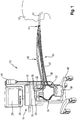
- FIG. 1 an embodiment of a ventilation device according to the invention is generally designated 10.
- the respiratory device 10 is used in the illustrated example for the artificial respiration of a human patient 12 in PSV mode.
- the respiratory device 10 has a housing 14, in which - a pressure change arrangement 16 and a control device 18 can be accommodated, which is not visible from outside because of the opaque housing material.
- the pressure variation assembly 16 is constructed in a manner known per se and may include a pump, a compressor, a blower, a pressure vessel, a reducing valve, and the like.
- the respiratory device 10 in a conventional manner an inspiratory valve 20 and an expiratory valve 22.
- the control device 18 is usually realized as a computer or microprocessor. It includes an in FIG. 1 Not shown storage device to save necessary for the operation of the ventilation device 10 necessary data and if necessary to call.
- the storage device may be in network operation Also located outside of the housing 14 and be connected by a data transmission connection to the controller 18.
- the data transmission connection may be formed by a cable or a radio link.
- the memory device is preferably integrated in the control device 18 or at least accommodated in the same housing 14 as the latter.
- the respiration device 10 can have a data input 24, which can be found in the in FIG. 1 represented example is represented by a keyboard.
- a data input 24 can be found in the in FIG. 1 represented example is represented by a keyboard.
- the keyboard is not the only data input of the controller 18.
- the controller 18 may receive data via various data inputs, such as a network line, radio link, or via sensor ports 26, discussed in detail below ,
- the respiratory device 10 may include an output device 28, in the example shown a screen.
- the patient 12 is connected to the respirator 10, more specifically to the pressure modifier assembly 16 in the housing 14, via a breathing gas conduit assembly 30.
- the patient 12 is intubated for this purpose.
- the tube 31 forms a patient interface of the ventilator 10.
- the patient interface may include a mask covering the nose and mouth.
- the respirator 10 also has an in FIG. 1 not shown connection formation for connection to a breathing gas supply.
- this connection formation can be an intake pipe, through which ambient air - if desired with the interposition of a filter - can be sucked into the breathing gas line arrangement 30 from the immediate surroundings of the ventilator 10.
- the connection formation may also be a flow line coupling be, by means of which the ventilator with a gas supply - be it air or oxygen - connectable.
- the gas supply can be, for example, a gas container or a collective supply, as it is installed in clinics as part of the building services.
- the breathing gas line arrangement 30 has an inspiratory tube 32, via which fresh breathing gas can be conducted from the pressure change arrangement 16 into the lungs of the patient 12.
- the inspiration tube 32 may be interrupted and have a first inspiratory tube 34 and a second inspiratory tube 36, between which a conditioning device 38 for targeted moistening and possibly also temperature control of the patient 12 supplied fresh breathing gas can be provided.
- the conditioning device 38 may be connected to an external fluid reservoir 40, via which water for humidification or else a medicament, for example for inhibiting inflammation or for expanding the respiratory tract, can be supplied to the conditioning device 38.
- volatile anesthetics can be delivered in a controlled manner to the patient 12 via the ventilation device 10.
- the conditioning device 38 ensures that the fresh breathing gas is supplied to the patient 12 with a predetermined moisture content, optionally with the addition of a drug aerosol and at a predetermined temperature.
- the breathing gas line arrangement 30 also has an expiratory tube 42, via which metabolized respiratory gas is blown out of the lungs of the patient 12 into the atmosphere.
- the inspiratory tube 32 is coupled to the inspiration valve 20, the expiratory tube 42 to the expiratory valve 22. Only one of the two valves is opened at the same time for the passage of a gas flow.
- the actuation control of the valves 20 and 22 is likewise effected by the control device 18.
- the exhalation valve 22 is initially closed for the duration of the inspiration phase, and the inspiration valve 20 is opened, so that fresh breathing gas can be conducted from the housing 14 to the patient 12.
- a flow of the fresh respiratory gas is effected by targeted pressure increase of the respiratory gas by the pressure change arrangement 16. Due to the increase in pressure, the fresh respiratory gas flows into the lungs of the patient 12 and expands there the body area near the lungs, ie in particular the thorax, against the individual elasticity of the body parts close to the lungs. As a result, the gas pressure inside the lung of the patient 12 also increases.
- the inspiration valve 20 is closed and the expiratory valve 22 is opened. It begins the expiratory phase. Due to the increased gas pressure of the respiratory gas located in the lungs of the patient 12 until the end of the inspiration phase, this gas flows into the atmosphere after the expiratory valve 22 has been opened, the gas pressure in the lungs of the patient 12 decreasing as the flow duration progresses. For example, when the gas pressure in the lungs 12 reaches a positive end-expiratory pressure set at the respirator 10, ie a slightly higher pressure than the atmospheric pressure, the expiratory phase is terminated with the closing of the expiratory valve 22 and another ventilation cycle follows. This can be one of several trigger criteria, by the presence of which the control device can trigger a reversal of the ventilator from expiratory to inspiratory operation.
- the patient 12 is supplied with the so-called respiratory tidal volume, ie the respiratory gas volume per breath.
- the respiratory device 10, in particular the control device 18, is designed to repeat respiratory operating parameters that characterize the ventilation mode of the respiratory device 10 during the ventilator operation to update or to determine to ensure that the ventilator is tuned as optimally as possible to each patient to be respirated 12 at any time.
- the determination of one or more ventilation operating parameters with the ventilation frequency, so that for each ventilation cycle current and thus optimally adapted to the patient 12 ventilation operating parameters can be provided.
- the respirator 10 is communicatively coupled to at least one of a flow sensor 44, preferably further sensors, such as a pressure sensor for measuring respiratory gas pressure in the breathing gas conduit assembly 30.
- the flow sensor 44 detects the respiratory gas flow prevailing in the breathing gas line arrangement 30 and outputs a signal representing the respiratory gas flow or the respiratory gas flow.
- the flow sensor 44 is preferably coupled to the data inputs 26 of the control device 18 by means of a sensor line arrangement 46.
- the sensor lead 46 may or may not include electrical signal transmission lines. It can also have hose lines which transmit the prevailing in the flow direction on both sides of the flow sensor 44 gas pressure to the data inputs 26, where these of in FIG. 1 not shown pressure sensors are quantified.
- respiration device 10 can be accommodated as a mobile respiration device 10 on a rollable frame 48.
- the flow sensor 44 is preferably located in a portion of the breathing gas conduit assembly 30 in which it can sense both the inspiratory flow and the expiratory flow. Alternatively or for redundancy reasons, in addition, at least one further flow sensor may be provided in the inspiration hose 32 and / or in the expiration hose 42 and / or in the housing 14.
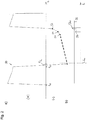
- FIG. 2a is exemplary and roughly schematically illustrated a temporal flow waveform 50, as it turns out, when the patient 12 of FIG. 1 is a COPD patient.
- the inspiratory process begins at time to, at which the controller 18 initiates the inspiratory process described above and increases the pressure in the inspiratory line 32 to a preset inspiratory pressure.
- the respiratory gas flow increases rapidly, for example as a volumetric flow in volume per unit of time, and then gradually decreases in magnitude as the lung is filled with fresh respiratory gas.
- the respiratory gas flow toward the patient 12 or into the patient 12 is, as agreed, subject to a positive sign.
- the amount of the slope or the slope of the flow waveform 50 between the support points 52 and 54 changes in comparison to the previous in the support point 52 bases.
- the slope is increasing.
- the slope of the flux waveform 50 again changes between the bases 54 and 56. The slope increases again.
- FIG. 2b is about the time axis t, correlated with the time axis t of FIG. 2a , plotted the increase in steepness. It is, as it is the representation of the flow waveform in FIG. 2a in the area of the interpolation points 52 to 56, the change in the steepness of the flux waveform 50 from the interpolation point 52 to the interpolation point 54 is plotted lower than the change in the steepness of the course 50 between the interpolation points 54 and 56 compared to the previous curve.
- the changes in the slope are respectively assigned to the temporally later interpolation points of a pair of interpolation points used for calculating the steepness, ie the interpolation points 54 and 56.
- a slope change threshold 58 is entered, which is used as a trigger criterion for triggering a transition from the expiratory operation to the inspiratory operation of the ventilation device 10.
- the slope change threshold 58 is the example in FIG. 2b for COPD patients, so that the 54s change value, at which the patient is still in the expiratory phase and has not made his own effort for inspiration, is below the slope change threshold 58.
- the modifier 56s returns to a typical COPD patient value when exercising its own inspiratory effort, such that this value exceeds the transconductance threshold 58, thus causing the controller 18 to switch the ventilator 10 from an expiratory mode to an inspiratory mode.
- a temporal threshold 60 is stored in the control device 18, from which only a change in the slope of the temporal flow signal curve 50 to provide a Trigger signal is observed.
- the temporal threshold 60 may be, for example, a predetermined period of time from the closing of the inspiratory valve 20 or from the opening of the expiratory valve 22.
- FIGS. 3a and 3b are den FIGS. 2a and 2b respectively corresponding representation of a flow waveform 150 for an ARDS patient shown.
- ARDS patients have a so-called restruc- tive respiratory system whose compliance is very low. The respiratory system is less elastic than in respiratory healthy patients. In COPD patients, on the other hand, the resistance of the respiratory system to respiratory healthy patients is increased.
- the flow waveform 150 is therefore generally steeper than in respiratory healthy patients and especially steeper than COPD patients. The maximum amounts of the river reached are also larger.
- FIGS. 3a and 3b Same and functionally identical details as in the FIGS. 2a and 2b are in the FIGS. 3a and 3b denoted by the same reference numerals but increased by the number 100.
- the expiratory flow of gas at the beginning of the expiratory phase reaches a value higher than in the case of a COPD patient, which is due to the obstructive breathing of the COPD patient as well as the low compliance of the ARDS patient.
- the expiratory flow of respiratory gas falls in the ARDS patient FIG. 3a faster than the COPD patient.
- the slope of the flow waveform in the ARDS patient usually changes several times during the expiratory phase.
- trigger criterion for the presently discussed trigger criteria preferably only those changes in the slope of the flow waveform 150 are considered, in which the slope of the flow waveform 150 increases, in which therefore the Curvature of the flux waveform 150 as viewed from the positive infinity the ordinate has a concave shape, while convex changes in steepness, at which the flux waveform 150 becomes flatter, are not considered at all.
- the slope change threshold 158 for ARDS patients is therefore advantageously chosen larger than that for COPD patients.
- a corresponding slope change threshold for respiratory healthy patients could be between thresholds 58 and 158.
- the assisted ventilated ARDS patient in the PSV mode begins to aspirate breathing gas, which leads to a considerable increase in the steepness of the flow waveform 150.
- the course section between the support points 154 and 156 is significantly steeper or has a significantly greater slope than the immediately preceding course section between the support points 152 and 154. Due to the own inspiratory effort of at least occasionally spontaneously respiring during respiration ARDS patient finds this increase in the flow waveform right down to a positive flow signal.
- the associated change value 156s is in FIG. 3b shown. It exceeds that for ARDS patients defined slope change threshold 158 and thus triggers a changeover from expiratory to inspiratory operation of the ventilator 10 from.
- a data memory of the ventilator 10 may include, in the form of a map, a table, a stored function or approximation function, and the like, a relationship between the slope change threshold to be applied in a ventilator case and an expiratory time constant characterizing the condition of the patient 12's respiratory system.
- control device 18 can then use the stored relationship to query the steepness change threshold to be used for the patient 12 currently to be ventilated or to determine it by arithmetic operations.
- the expiratory time constant of the patient 12 currently being ventilated may be manually entered into the ventilator 10 by medical personnel, if known, such as to have at least an initial value for the slope change threshold.
- the control device 18 is designed to determine the expiratory time constant of the respective patient 12 to be ventilated on the basis of the sensor information that is accessible to it.
- the expiratory time constant may be carried out solely on the basis of the information received from the flow sensor 44.
- the expiratory time constant can be determined on the basis of the respiratory gas volume exhaled during an expiratory phase and the maximum respiratory gas flow which has occurred during the same expiratory phase. Further possible investigation methods for determining the expiratory time constant have already been mentioned above in the introduction to the description.
- the ventilator 10 is able to determine the condition of the respiratory system of the patient 12 and based on the determined state of the respiratory system adapt the slope-dependent trigger criterion for a changeover of the ventilator 10 from expiratory to inspiratory operation to the respective patient to be ventilated.
Landscapes
- Health & Medical Sciences (AREA)
- Pulmonology (AREA)
- Heart & Thoracic Surgery (AREA)
- Engineering & Computer Science (AREA)
- Anesthesiology (AREA)
- Biomedical Technology (AREA)
- Emergency Medicine (AREA)
- Hematology (AREA)
- Life Sciences & Earth Sciences (AREA)
- Animal Behavior & Ethology (AREA)
- General Health & Medical Sciences (AREA)
- Public Health (AREA)
- Veterinary Medicine (AREA)
- Measurement Of The Respiration, Hearing Ability, Form, And Blood Characteristics Of Living Organisms (AREA)
Applications Claiming Priority (2)
| Application Number | Priority Date | Filing Date | Title |
|---|---|---|---|
| DE102016206442.8A DE102016206442A1 (de) | 2016-04-15 | 2016-04-15 | Beatmungsgerät mit verbesserter Synchronität beim Übergang von exspiratorischem zu inspiratorischem Betrieb |
| PCT/EP2017/058577 WO2017178440A1 (de) | 2016-04-15 | 2017-04-10 | Beatmungsgerät mit verbesserter synchronität beim übergang von exspiratorischem zu inspiratorischem betrieb |
Publications (2)
| Publication Number | Publication Date |
|---|---|
| EP3247437A1 EP3247437A1 (de) | 2017-11-29 |
| EP3247437B1 true EP3247437B1 (de) | 2018-10-31 |
Family
ID=58503650
Family Applications (1)
| Application Number | Title | Priority Date | Filing Date |
|---|---|---|---|
| EP17716248.4A Active EP3247437B1 (de) | 2016-04-15 | 2017-04-10 | Beatmungsgerät mit verbesserter synchronität beim übergang von exspiratorischem zu inspiratorischem betrieb |
Country Status (7)
| Country | Link |
|---|---|
| US (1) | US20200215283A9 (enExample) |
| EP (1) | EP3247437B1 (enExample) |
| JP (1) | JP2019511301A (enExample) |
| CN (1) | CN109069780A (enExample) |
| AU (1) | AU2017251164A1 (enExample) |
| DE (1) | DE102016206442A1 (enExample) |
| WO (1) | WO2017178440A1 (enExample) |
Families Citing this family (18)
| Publication number | Priority date | Publication date | Assignee | Title |
|---|---|---|---|---|
| DE102017006655A1 (de) * | 2017-07-13 | 2019-01-17 | GRÜNDLER GmbH | System zur Unterstützung der Atmung und Patientenset hierfür |
| DE102017008791B4 (de) * | 2017-09-20 | 2025-10-02 | Drägerwerk AG & Co. KGaA | Beatmungsgerät mit einer Steuerungseinheit |
| US12214124B2 (en) * | 2018-09-04 | 2025-02-04 | Fisher & Paykel Healthcare Limited | Support for a breathing assistance apparatus and/or accessories |
| JP7290406B2 (ja) * | 2018-10-03 | 2023-06-13 | 帝人ファーマ株式会社 | 呼吸用気体供給装置及びその制御方法 |
| CN110947062A (zh) * | 2019-03-31 | 2020-04-03 | 湖南明康中锦医疗科技发展有限公司 | 呼吸支持设备呼吸撤换判定方法 |
| DE102020002278A1 (de) * | 2019-04-24 | 2020-10-29 | Löwenstein Medical Technology S.A. | System zur Atemgasversorgung und Verfahren |
| WO2021068160A1 (zh) * | 2019-10-10 | 2021-04-15 | 深圳迈瑞生物医疗电子股份有限公司 | 一种通气切换控制方法及装置、医用通气设备、存储介质 |
| DE102019129549A1 (de) * | 2019-10-31 | 2021-05-06 | Hamilton Medical Ag | Verfahren zur Durchführung eines automatisiert eine Lungenüberdehnung vermeidenden P/V-Manövers und zur Ausführung des Verfahrens ausgebildete Beatmungsvorrichtung |
| CN114126691B (zh) * | 2019-12-03 | 2024-10-11 | 深圳迈瑞生物医疗电子股份有限公司 | 压力产生装置识别方法及系统、通气支持设备、存储介质 |
| CN111298255B (zh) * | 2020-02-22 | 2023-07-18 | 湖南城市学院 | 一种基于通气容量自动触发切换输出呼吸气压的呼吸机 |
| DE102020202798A1 (de) | 2020-03-05 | 2021-09-09 | Robert Bosch Gesellschaft mit beschränkter Haftung | Atemgasanalysegerät und Verfahren zu seinem Betrieb |
| CN111632241B (zh) * | 2020-06-08 | 2021-05-11 | 山东科技大学 | 一种湿化治疗仪控制系统 |
| US12073945B2 (en) * | 2020-06-30 | 2024-08-27 | Cerner Innovation, Inc. | Patient ventilator asynchrony detection |
| CN114681739B (zh) * | 2020-12-30 | 2024-07-30 | 深圳迈瑞生物医疗电子股份有限公司 | 麻醉呼吸设备及呼吸回路顺应性检测方法 |
| DE102021110429A1 (de) * | 2021-04-23 | 2022-10-27 | Drägerwerk AG & Co. KGaA | Beatmungsgerät zur maschinellen Beatmung eines Patienten |
| CN114917440B (zh) * | 2022-06-01 | 2025-10-24 | 四川千里倍益康医疗科技股份有限公司 | 呼吸检测方法、脉冲式制氧机的控制方法及脉冲式制氧机 |
| CN116510141A (zh) * | 2023-04-10 | 2023-08-01 | 北京谊安和顺科技有限公司 | 流速控制方法、流速控制装置及呼吸机 |
| DE102025115018A1 (de) * | 2024-04-25 | 2025-10-30 | Löwenstein Medical Technology S.A. | Beatmungsgerät mit Display |
Family Cites Families (16)
| Publication number | Priority date | Publication date | Assignee | Title |
|---|---|---|---|---|
| US3834382A (en) | 1972-09-05 | 1974-09-10 | Johnson Service Co | Fluidic respirator control system with patient triggering response means |
| US5632269A (en) * | 1989-09-22 | 1997-05-27 | Respironics Inc. | Breathing gas delivery method and apparatus |
| DE4122069A1 (de) * | 1991-07-04 | 1993-01-07 | Draegerwerk Ag | Verfahren zur erkennung der atemphasen eines patienten bei assistierenden beatmungsverfahren |
| DE4432219C1 (de) | 1994-09-10 | 1996-04-11 | Draegerwerk Ag | Beatmungssystem zur Versorgung eines Patienten mit Atemgas |
| US5551419A (en) * | 1994-12-15 | 1996-09-03 | Devilbiss Health Care, Inc. | Control for CPAP apparatus |
| DE19528113C2 (de) * | 1995-08-01 | 2002-09-12 | Univ Ludwigs Albert | Beatmungseinrichtung |
| JP2926392B2 (ja) * | 1996-06-03 | 1999-07-28 | レスピロニクス,インコーポレイテッド | 検出装置 |
| DE10031079A1 (de) * | 2000-06-30 | 2002-02-07 | Map Gmbh | Vorrichtung zur Erfassung der Atmungsstätigkeit einer Person sowie Vorrichtung zur Vorgabe physikalischer Parameter bei der Zufuhr eines Atemgases |
| US6439229B1 (en) | 2000-08-08 | 2002-08-27 | Newport Medical Instruments, Inc. | Pressure support ventilation control system and method |
| DE102004014538A1 (de) * | 2004-03-23 | 2005-10-13 | Seleon Gmbh | Verfahren zur Steuerung eines BiLevel-Geräts sowie BiLevel-Gerät |
| CN101547716B (zh) * | 2005-11-16 | 2013-06-26 | 心肺技术公司 | 旁流型呼吸气体监测系统和方法 |
| DE102007052897B4 (de) * | 2007-11-07 | 2013-02-21 | Dräger Medical GmbH | Verfahren zum automatischen Steuern eines Beatmungssystems sowie zugehöriges Beatmungssystem |
| EP2608832B1 (en) * | 2010-08-27 | 2022-09-28 | ResMed Pty Ltd | Adaptive cycling for respiratory treatment apparatus |
| US9592356B2 (en) * | 2010-09-10 | 2017-03-14 | Koninklijke Philips N.V. | System and method for identifying breathing transitions |
| EP2686050B1 (en) * | 2011-03-18 | 2018-04-25 | Maquet Critical Care AB | Breathing apparatus and method for support ventilation |
| CN103182120B (zh) * | 2011-12-30 | 2016-06-15 | 北京谊安医疗系统股份有限公司 | 有创呼吸机在无创通气模式下人机同步的装置 |
-
2016
- 2016-04-15 DE DE102016206442.8A patent/DE102016206442A1/de not_active Withdrawn
-
2017
- 2017-04-10 AU AU2017251164A patent/AU2017251164A1/en not_active Abandoned
- 2017-04-10 EP EP17716248.4A patent/EP3247437B1/de active Active
- 2017-04-10 US US16/093,818 patent/US20200215283A9/en not_active Abandoned
- 2017-04-10 JP JP2018550597A patent/JP2019511301A/ja not_active Ceased
- 2017-04-10 WO PCT/EP2017/058577 patent/WO2017178440A1/de not_active Ceased
- 2017-04-10 CN CN201780023459.5A patent/CN109069780A/zh active Pending
Also Published As
| Publication number | Publication date |
|---|---|
| CN109069780A (zh) | 2018-12-21 |
| WO2017178440A1 (de) | 2017-10-19 |
| JP2019511301A (ja) | 2019-04-25 |
| DE102016206442A1 (de) | 2017-10-19 |
| EP3247437A1 (de) | 2017-11-29 |
| AU2017251164A1 (en) | 2018-09-13 |
| US20200215283A9 (en) | 2020-07-09 |
| US20190134331A1 (en) | 2019-05-09 |
Similar Documents
| Publication | Publication Date | Title |
|---|---|---|
| EP3247437B1 (de) | Beatmungsgerät mit verbesserter synchronität beim übergang von exspiratorischem zu inspiratorischem betrieb | |
| DE102006030520B3 (de) | Vorrichtung zum Versorgen eines Patienten mit Atemgas und Verfahren zum Regeln einer Beatmungs-Vorrichtung | |
| EP1960025B1 (de) | Schlauchsystem für beatmungsgeräte | |
| EP3691723B1 (de) | Beatmungsvorrichtung mit automatisierter erfassung eines fehlers eines durchflusssensors unter berücksichtigung von spontanatmung | |
| EP3344317B1 (de) | Beatmungsvorrichtung mit fehlererfassung für durchflusssensoren | |
| EP3270993B1 (de) | Beatmungsgeräte | |
| CH701124B1 (de) | Beatmungsgerät und Einstellverfahren hierfür. | |
| DE102017217859A1 (de) | Beatmungsvorrichtung mit fluss- und drucksignalbasierter Erfassung von Fehlern eines Durchflusssensors der Vorrichtung | |
| EP4141846B1 (de) | System zur simulation der atmung eines lebewesens | |
| DE102016109528A1 (de) | Verfahren und Vorrichtung zur Beatmung eines Patienten | |
| DE102017008791A1 (de) | Verfahren zum Betrieb eines Beatmungsgeräts und nach dem Verfahren arbeitendes Beatmungsgerät | |
| EP3957347B1 (de) | Beatmungsgerät für high-flow-sauerstofftherapie | |
| EP1735036A1 (de) | Beatmungseinrichtung sowie damit durchführbares verfahren zur beatmung eines patienten | |
| DE102007054390A1 (de) | Verfahren zur Erfassung eines rückgeatmeten Ausatemgasvolumens in einem Beatmungssystem | |
| EP3261698B1 (de) | Beatmungsvorrichtung | |
| DE102020123138B3 (de) | Verfahren und Vorrichtung zur automatischen Festlegung der Sollfrequenz eines Beatmungsgeräts | |
| EP1586343A1 (de) | Vorrichtung zur Beatmung sowie Verfahren zur Steuerung eines Beatmungsgerätes | |
| DE102014119374B4 (de) | Beatmungssystem | |
| DE102006018042B4 (de) | Beatmungsgerät | |
| DE102024107611A1 (de) | Medizingerät zu einer Beatmung eines Lebewesens, Verfahren und Computerprogramm zum Betrieb eines Medizingerätes | |
| WO2021083981A1 (de) | Verfahren zur durchführung eines automatisiert eine lungenüberdehnung vermeidenden p/v-manövers und zur ausführung des verfahrens ausgebildete beatmungsvorrichtung | |
| EP4129377A1 (de) | Beatmungssystem mit sprechfunktion | |
| DE102022108124A1 (de) | Beatmungsvorrichtung und -verfahren mit Spontanatmungsphasen | |
| EP4251246A1 (de) | Erkennung von asynchronien bei der beatmung | |
| EP3097938A1 (de) | Vorrichtung zur applikation eines medizinischen gases an einen patienten |
Legal Events
| Date | Code | Title | Description |
|---|---|---|---|
| STAA | Information on the status of an ep patent application or granted ep patent |
Free format text: STATUS: UNKNOWN |
|
| STAA | Information on the status of an ep patent application or granted ep patent |
Free format text: STATUS: THE INTERNATIONAL PUBLICATION HAS BEEN MADE |
|
| PUAI | Public reference made under article 153(3) epc to a published international application that has entered the european phase |
Free format text: ORIGINAL CODE: 0009012 |
|
| STAA | Information on the status of an ep patent application or granted ep patent |
Free format text: STATUS: REQUEST FOR EXAMINATION WAS MADE |
|
| 17P | Request for examination filed |
Effective date: 20170720 |
|
| AK | Designated contracting states |
Kind code of ref document: A1 Designated state(s): AL AT BE BG CH CY CZ DE DK EE ES FI FR GB GR HR HU IE IS IT LI LT LU LV MC MK MT NL NO PL PT RO RS SE SI SK SM TR |
|
| AX | Request for extension of the european patent |
Extension state: BA ME |
|
| GRAP | Despatch of communication of intention to grant a patent |
Free format text: ORIGINAL CODE: EPIDOSNIGR1 |
|
| STAA | Information on the status of an ep patent application or granted ep patent |
Free format text: STATUS: GRANT OF PATENT IS INTENDED |
|
| INTG | Intention to grant announced |
Effective date: 20180601 |
|
| GRAS | Grant fee paid |
Free format text: ORIGINAL CODE: EPIDOSNIGR3 |
|
| GRAA | (expected) grant |
Free format text: ORIGINAL CODE: 0009210 |
|
| STAA | Information on the status of an ep patent application or granted ep patent |
Free format text: STATUS: THE PATENT HAS BEEN GRANTED |
|
| RIN1 | Information on inventor provided before grant (corrected) |
Inventor name: NOVOTNI, DOMINIK Inventor name: MEYER, JOHANNES BJOERN THOMAS |
|
| DAV | Request for validation of the european patent (deleted) | ||
| DAX | Request for extension of the european patent (deleted) | ||
| AK | Designated contracting states |
Kind code of ref document: B1 Designated state(s): AL AT BE BG CH CY CZ DE DK EE ES FI FR GB GR HR HU IE IS IT LI LT LU LV MC MK MT NL NO PL PT RO RS SE SI SK SM TR |
|
| REG | Reference to a national code |
Ref country code: CH Ref legal event code: EP Ref country code: GB Ref legal event code: FG4D Free format text: NOT ENGLISH |
|
| REG | Reference to a national code |
Ref country code: AT Ref legal event code: REF Ref document number: 1058647 Country of ref document: AT Kind code of ref document: T Effective date: 20181115 |
|
| REG | Reference to a national code |
Ref country code: DE Ref legal event code: R096 Ref document number: 502017000308 Country of ref document: DE |
|
| REG | Reference to a national code |
Ref country code: IE Ref legal event code: FG4D Free format text: LANGUAGE OF EP DOCUMENT: GERMAN |
|
| REG | Reference to a national code |
Ref country code: CH Ref legal event code: NV Representative=s name: E. BLUM AND CO. AG PATENT- UND MARKENANWAELTE , CH |
|
| REG | Reference to a national code |
Ref country code: SE Ref legal event code: TRGR |
|
| REG | Reference to a national code |
Ref country code: NL Ref legal event code: FP |
|
| REG | Reference to a national code |
Ref country code: NO Ref legal event code: T2 Effective date: 20181031 |
|
| REG | Reference to a national code |
Ref country code: LT Ref legal event code: MG4D |
|
| PG25 | Lapsed in a contracting state [announced via postgrant information from national office to epo] |
Ref country code: ES Free format text: LAPSE BECAUSE OF FAILURE TO SUBMIT A TRANSLATION OF THE DESCRIPTION OR TO PAY THE FEE WITHIN THE PRESCRIBED TIME-LIMIT Effective date: 20181031 Ref country code: IS Free format text: LAPSE BECAUSE OF FAILURE TO SUBMIT A TRANSLATION OF THE DESCRIPTION OR TO PAY THE FEE WITHIN THE PRESCRIBED TIME-LIMIT Effective date: 20190228 Ref country code: HR Free format text: LAPSE BECAUSE OF FAILURE TO SUBMIT A TRANSLATION OF THE DESCRIPTION OR TO PAY THE FEE WITHIN THE PRESCRIBED TIME-LIMIT Effective date: 20181031 Ref country code: LV Free format text: LAPSE BECAUSE OF FAILURE TO SUBMIT A TRANSLATION OF THE DESCRIPTION OR TO PAY THE FEE WITHIN THE PRESCRIBED TIME-LIMIT Effective date: 20181031 Ref country code: FI Free format text: LAPSE BECAUSE OF FAILURE TO SUBMIT A TRANSLATION OF THE DESCRIPTION OR TO PAY THE FEE WITHIN THE PRESCRIBED TIME-LIMIT Effective date: 20181031 Ref country code: PL Free format text: LAPSE BECAUSE OF FAILURE TO SUBMIT A TRANSLATION OF THE DESCRIPTION OR TO PAY THE FEE WITHIN THE PRESCRIBED TIME-LIMIT Effective date: 20181031 Ref country code: BG Free format text: LAPSE BECAUSE OF FAILURE TO SUBMIT A TRANSLATION OF THE DESCRIPTION OR TO PAY THE FEE WITHIN THE PRESCRIBED TIME-LIMIT Effective date: 20190131 Ref country code: LT Free format text: LAPSE BECAUSE OF FAILURE TO SUBMIT A TRANSLATION OF THE DESCRIPTION OR TO PAY THE FEE WITHIN THE PRESCRIBED TIME-LIMIT Effective date: 20181031 |
|
| PG25 | Lapsed in a contracting state [announced via postgrant information from national office to epo] |
Ref country code: GR Free format text: LAPSE BECAUSE OF FAILURE TO SUBMIT A TRANSLATION OF THE DESCRIPTION OR TO PAY THE FEE WITHIN THE PRESCRIBED TIME-LIMIT Effective date: 20190201 Ref country code: RS Free format text: LAPSE BECAUSE OF FAILURE TO SUBMIT A TRANSLATION OF THE DESCRIPTION OR TO PAY THE FEE WITHIN THE PRESCRIBED TIME-LIMIT Effective date: 20181031 Ref country code: PT Free format text: LAPSE BECAUSE OF FAILURE TO SUBMIT A TRANSLATION OF THE DESCRIPTION OR TO PAY THE FEE WITHIN THE PRESCRIBED TIME-LIMIT Effective date: 20190301 Ref country code: AL Free format text: LAPSE BECAUSE OF FAILURE TO SUBMIT A TRANSLATION OF THE DESCRIPTION OR TO PAY THE FEE WITHIN THE PRESCRIBED TIME-LIMIT Effective date: 20181031 |
|
| PG25 | Lapsed in a contracting state [announced via postgrant information from national office to epo] |
Ref country code: IT Free format text: LAPSE BECAUSE OF FAILURE TO SUBMIT A TRANSLATION OF THE DESCRIPTION OR TO PAY THE FEE WITHIN THE PRESCRIBED TIME-LIMIT Effective date: 20181031 Ref country code: DK Free format text: LAPSE BECAUSE OF FAILURE TO SUBMIT A TRANSLATION OF THE DESCRIPTION OR TO PAY THE FEE WITHIN THE PRESCRIBED TIME-LIMIT Effective date: 20181031 Ref country code: CZ Free format text: LAPSE BECAUSE OF FAILURE TO SUBMIT A TRANSLATION OF THE DESCRIPTION OR TO PAY THE FEE WITHIN THE PRESCRIBED TIME-LIMIT Effective date: 20181031 |
|
| REG | Reference to a national code |
Ref country code: DE Ref legal event code: R097 Ref document number: 502017000308 Country of ref document: DE |
|
| PG25 | Lapsed in a contracting state [announced via postgrant information from national office to epo] |
Ref country code: SK Free format text: LAPSE BECAUSE OF FAILURE TO SUBMIT A TRANSLATION OF THE DESCRIPTION OR TO PAY THE FEE WITHIN THE PRESCRIBED TIME-LIMIT Effective date: 20181031 Ref country code: EE Free format text: LAPSE BECAUSE OF FAILURE TO SUBMIT A TRANSLATION OF THE DESCRIPTION OR TO PAY THE FEE WITHIN THE PRESCRIBED TIME-LIMIT Effective date: 20181031 Ref country code: RO Free format text: LAPSE BECAUSE OF FAILURE TO SUBMIT A TRANSLATION OF THE DESCRIPTION OR TO PAY THE FEE WITHIN THE PRESCRIBED TIME-LIMIT Effective date: 20181031 Ref country code: SM Free format text: LAPSE BECAUSE OF FAILURE TO SUBMIT A TRANSLATION OF THE DESCRIPTION OR TO PAY THE FEE WITHIN THE PRESCRIBED TIME-LIMIT Effective date: 20181031 |
|
| PLBE | No opposition filed within time limit |
Free format text: ORIGINAL CODE: 0009261 |
|
| STAA | Information on the status of an ep patent application or granted ep patent |
Free format text: STATUS: NO OPPOSITION FILED WITHIN TIME LIMIT |
|
| 26N | No opposition filed |
Effective date: 20190801 |
|
| PG25 | Lapsed in a contracting state [announced via postgrant information from national office to epo] |
Ref country code: SI Free format text: LAPSE BECAUSE OF FAILURE TO SUBMIT A TRANSLATION OF THE DESCRIPTION OR TO PAY THE FEE WITHIN THE PRESCRIBED TIME-LIMIT Effective date: 20181031 |
|
| REG | Reference to a national code |
Ref country code: BE Ref legal event code: MM Effective date: 20190430 |
|
| PG25 | Lapsed in a contracting state [announced via postgrant information from national office to epo] |
Ref country code: MC Free format text: LAPSE BECAUSE OF FAILURE TO SUBMIT A TRANSLATION OF THE DESCRIPTION OR TO PAY THE FEE WITHIN THE PRESCRIBED TIME-LIMIT Effective date: 20181031 Ref country code: LU Free format text: LAPSE BECAUSE OF NON-PAYMENT OF DUE FEES Effective date: 20190410 |
|
| PG25 | Lapsed in a contracting state [announced via postgrant information from national office to epo] |
Ref country code: BE Free format text: LAPSE BECAUSE OF NON-PAYMENT OF DUE FEES Effective date: 20190430 |
|
| PG25 | Lapsed in a contracting state [announced via postgrant information from national office to epo] |
Ref country code: TR Free format text: LAPSE BECAUSE OF FAILURE TO SUBMIT A TRANSLATION OF THE DESCRIPTION OR TO PAY THE FEE WITHIN THE PRESCRIBED TIME-LIMIT Effective date: 20181031 |
|
| PG25 | Lapsed in a contracting state [announced via postgrant information from national office to epo] |
Ref country code: CY Free format text: LAPSE BECAUSE OF FAILURE TO SUBMIT A TRANSLATION OF THE DESCRIPTION OR TO PAY THE FEE WITHIN THE PRESCRIBED TIME-LIMIT Effective date: 20181031 |
|
| PG25 | Lapsed in a contracting state [announced via postgrant information from national office to epo] |
Ref country code: MT Free format text: LAPSE BECAUSE OF FAILURE TO SUBMIT A TRANSLATION OF THE DESCRIPTION OR TO PAY THE FEE WITHIN THE PRESCRIBED TIME-LIMIT Effective date: 20181031 Ref country code: HU Free format text: LAPSE BECAUSE OF FAILURE TO SUBMIT A TRANSLATION OF THE DESCRIPTION OR TO PAY THE FEE WITHIN THE PRESCRIBED TIME-LIMIT; INVALID AB INITIO Effective date: 20170410 |
|
| PG25 | Lapsed in a contracting state [announced via postgrant information from national office to epo] |
Ref country code: MK Free format text: LAPSE BECAUSE OF FAILURE TO SUBMIT A TRANSLATION OF THE DESCRIPTION OR TO PAY THE FEE WITHIN THE PRESCRIBED TIME-LIMIT Effective date: 20181031 |
|
| PGFP | Annual fee paid to national office [announced via postgrant information from national office to epo] |
Ref country code: NO Payment date: 20230322 Year of fee payment: 7 Ref country code: IE Payment date: 20230322 Year of fee payment: 7 |
|
| P01 | Opt-out of the competence of the unified patent court (upc) registered |
Effective date: 20230521 |
|
| PGFP | Annual fee paid to national office [announced via postgrant information from national office to epo] |
Ref country code: NL Payment date: 20230321 Year of fee payment: 7 |
|
| PGFP | Annual fee paid to national office [announced via postgrant information from national office to epo] |
Ref country code: CH Payment date: 20230502 Year of fee payment: 7 |
|
| PGFP | Annual fee paid to national office [announced via postgrant information from national office to epo] |
Ref country code: AT Payment date: 20230322 Year of fee payment: 7 |
|
| REG | Reference to a national code |
Ref country code: CH Ref legal event code: PL |
|
| REG | Reference to a national code |
Ref country code: NL Ref legal event code: MM Effective date: 20240501 |
|
| REG | Reference to a national code |
Ref country code: AT Ref legal event code: MM01 Ref document number: 1058647 Country of ref document: AT Kind code of ref document: T Effective date: 20240410 |
|
| PG25 | Lapsed in a contracting state [announced via postgrant information from national office to epo] |
Ref country code: NO Free format text: LAPSE BECAUSE OF NON-PAYMENT OF DUE FEES Effective date: 20240430 |
|
| PG25 | Lapsed in a contracting state [announced via postgrant information from national office to epo] |
Ref country code: NL Free format text: LAPSE BECAUSE OF NON-PAYMENT OF DUE FEES Effective date: 20240501 |
|
| PG25 | Lapsed in a contracting state [announced via postgrant information from national office to epo] |
Ref country code: AT Free format text: LAPSE BECAUSE OF NON-PAYMENT OF DUE FEES Effective date: 20240410 |
|
| PG25 | Lapsed in a contracting state [announced via postgrant information from national office to epo] |
Ref country code: NO Free format text: LAPSE BECAUSE OF NON-PAYMENT OF DUE FEES Effective date: 20240430 Ref country code: NL Free format text: LAPSE BECAUSE OF NON-PAYMENT OF DUE FEES Effective date: 20240501 Ref country code: AT Free format text: LAPSE BECAUSE OF NON-PAYMENT OF DUE FEES Effective date: 20240410 Ref country code: CH Free format text: LAPSE BECAUSE OF NON-PAYMENT OF DUE FEES Effective date: 20240430 |
|
| PG25 | Lapsed in a contracting state [announced via postgrant information from national office to epo] |
Ref country code: IE Free format text: LAPSE BECAUSE OF NON-PAYMENT OF DUE FEES Effective date: 20240410 |
|
| PGFP | Annual fee paid to national office [announced via postgrant information from national office to epo] |
Ref country code: DE Payment date: 20250319 Year of fee payment: 9 |
|
| PGFP | Annual fee paid to national office [announced via postgrant information from national office to epo] |
Ref country code: SE Payment date: 20260319 Year of fee payment: 10 |
|
| PGFP | Annual fee paid to national office [announced via postgrant information from national office to epo] |
Ref country code: GB Payment date: 20260319 Year of fee payment: 10 |
|
| PGFP | Annual fee paid to national office [announced via postgrant information from national office to epo] |
Ref country code: FR Payment date: 20260319 Year of fee payment: 10 |