EP3247278B1 - Stethoscope diaphragm - Google Patents
Stethoscope diaphragm Download PDFInfo
- Publication number
- EP3247278B1 EP3247278B1 EP16740512.5A EP16740512A EP3247278B1 EP 3247278 B1 EP3247278 B1 EP 3247278B1 EP 16740512 A EP16740512 A EP 16740512A EP 3247278 B1 EP3247278 B1 EP 3247278B1
- Authority
- EP
- European Patent Office
- Prior art keywords
- diaphragm
- disc
- features
- rim
- chestpiece
- Prior art date
- Legal status (The legal status is an assumption and is not a legal conclusion. Google has not performed a legal analysis and makes no representation as to the accuracy of the status listed.)
- Active
Links
Images


Classifications
-
- A—HUMAN NECESSITIES
- A61—MEDICAL OR VETERINARY SCIENCE; HYGIENE
- A61B—DIAGNOSIS; SURGERY; IDENTIFICATION
- A61B7/00—Instruments for auscultation
- A61B7/02—Stethoscopes
Definitions
- the present invention is related generally to the field of stethoscopes.
- the present invention is related to stethoscope diaphragms having a series of features.
- the diaphragms currently used on most stethoscopes include two pieces, the diaphragm and the rim. These pieces may be manufactured as two separate pieces or as a single, unitary piece. The rim is used to hold the diaphragm on the chestpiece.
- the present invention is defined in independent claim 1 and dependent claims 2 - 9 and relates to a stethoscope diaphragm including a disc and a rim.
- the rim includes a wall having a first end and a second end; a lip extending substantially perpendicularly from the first end of the wall; a bridge extending substantially perpendicularly from the second end of the wall; a fork extending from the bridge, wherein the fork includes an inner flange and an outer flange; and a plurality of features extending from the inner flange.
- the present invention is a diaphragm to be used with stethoscopes.
- the stethoscopes are tunable stethoscopes.
- the diaphragm includes a disc and a rim.
- the rim includes a plurality of features extending from the inner circumference of the rim which surrounds the underside of the disc. The plurality of features adds support to the disc and provides a uniform part.
- the diaphragm including the rim having the plurality of features allows for the diaphragm to be manufactured with a decreased number of defects.
- acoustical stiffness of the diaphragm designates the mechanical stiffness of the diaphragm as influenced by the mechanical stiffness of the diaphragm material itself, the thickness of the diaphragm, the shape of the diaphragm, the diameter of the diaphragm, and the manner in which the diaphragm is attached to the stethoscope head.
- plane of the diaphragm refers to the generally planar surface of the diaphragm (disc).
- the phrase "suspended diaphragm" designates a diaphragm having at least a suspension member as described below.
- the diaphragm and suspension member are operatively associated with an immobilization means as described below.
- the suspended diaphragm may be constructed according to the teachings of U.S. Pat. No. 4,440,258 to Packard .
- a stethoscope diaphragm according to the preamble of independent claim 1 is known from prior art document US 6,378,648 .
- a stethoscope 10 includes a chestpiece 12 formed of conventional material utilized in the fabrication of stethoscope chestpieces, for example, metals such as stainless steel and aluminum, metallic composites, plastic and wood.
- the chestpiece 12 is attached to a conventional headset such as that described in U.S. Pat. No. 4,200,169 which includes an elongated flexible tubing 14 that splits into flexible tubings 16 that run to ear tips 18.
- the lower end of the flexible tubing 14 is adapted to be coupled to a conventional stem fitting on the chestpiece 12.
- the coupling may utilize the indexing detent as taught in U.S. Pat. No. 4,770,270 .
- Binaural tubes for stethoscopes can be prepared in accordance with the teachings of U.S. Pat. Nos. 5,111,904 ; 5,380,182 ; and 5,324,471 to Packard et al.
- the ear tips 18 are sized and shaped to engage the surfaces of the user's ears.
- the ear tips 18 may include any suitable ear tips.
- the ear tips 18 include the soft ear tips disclosed in U.S. Pat. Nos. 4,852,684 ; 4,913,259 and 5,449,865 .
- the chestpiece 12 is a dual-sided chestpiece including a first sound collecting side 20 and a second sound collecting side 22.
- the diaphragm of the present invention is discussed with respect to a dual-sided chestpiece, the diaphragm may also be used with a single-sided chestpiece without limiting the scope of the present invention.
- the stethoscope 10 affords tuning in of sound while using either the first side 20 or the second side 22 of the chestpiece 12.
- the first sound collecting side 20 is sized and shaped to collect sounds from adult patients.
- the second sound collecting side 22 is sized and shaped to afford sufficient surface contact on pediatric or thin patients.
- the second sound collecting side 22 is also substantially smaller than the first sound collecting side to afford easier access to remote or difficult to reach locations.
- the first sound collecting side 20 has a first recess 24 with an innermost central portion 26, an outer rim portion 28, and an acoustic channel 30, 32 communicating with the central portion 26.
- a first diaphragm 34 is also located on the first sound collecting side 20.
- the first diaphragm 34 includes a rim 36 and disc 38 positioned within the rim 36, together having a peripheral edge portion and a predetermined surface contour overlying at least a portion of the first recess 24. As shown in FIGS. 3A and 3B , the first diaphragm 34 is moveably connected to or "operatively associated" with the outer rim portion 28 of the first recess 24.
- the first diaphragm 34 is positioned on the chestpiece 12 such that there can be movement of the first diaphragm 34 in a direction substantially perpendicular to the plane of the first diaphragm 34 between: 1) a normal outer position to which the first diaphragm 34 is biased and 2) an inner position more closely adjacent the central portion of the first recess 24. This movement is accomplished without substantially changing the surface contour of or the lateral tension in the first diaphragm 34.
- a first immobilizing means 40 is situated on the first sound collecting side 20 of the chestpiece 12.
- the first immobilizing means 40 is located within the first recess 24. Together with the central portion of the first recess 24, the first immobilizing means 40 forms a shallow recess within the first recess 24.
- the immobilizing means 40 is sized and shaped to be contacted by the first diaphragm 34. In FIG. 3B , it is the first diaphragm 34 which contacts the immobilizing means 40. When the first diaphragm 34 is in the inner position, the immobilizing means 40 immobilizes the first diaphragm 34.
- the first sound collecting side 20 of the chestpiece 12 will pass low frequency (bass) sounds and gradually attenuate sounds with higher frequencies when the first diaphragm 34 is in the outer position and between the outer and inner positions.
- the acoustical stiffness of the first diaphragm 34 will be significantly higher than the acoustical stiffness of the first diaphragm 34 when it is in the outer position, so that the first sound collecting side 20 of the chestpiece 12 will attenuate or block low frequency sounds while leaving higher frequency sounds unchanged.
- a physician would simply modify the manual pressure exerted on the chestpiece 12 in order to switch between the outer and inner positions.
- the level of bass attenuation varies from about 3 to about 21 dB.
- the second sound collecting side 22 is adapted to include a second suspended diaphragm.
- the second sound collecting side 22 has many reference characters similar to the reference characters used to describe elements of the first sound collecting side 20 except that the reference character "B" has been added.
- the second sound collecting side 22 has a second recess 24B with an innermost central portion 26B, an outer rim portion 28B, and an acoustic channel 30, 32' communicating with the central portion 26B.
- the second sound collecting side 22 has a second diaphragm 34B including a rim 36B and disc 38B positioned within the rim 36B, together having with a peripheral edge portion and a predetermined surface contour overlying at least a portion of the second recess 24B.
- the second diaphragm 34B is moveably associated with the outer rim portion 28B of the second recess 24B.
- a second immobilizing means 40B is situated on the second sound collecting side 22 of the chestpiece 12.
- the second immobilizing means 40B is located within the second recess 24B. Together with the central portion 26B of the second recess 24B, the second immobilizing means 40B forms a shallow recess within the second recess 24B.
- the second immobilizing means 40B is sized and shaped to be contacted by the second diaphragm 34B. When the second diaphragm 34B is in the inner position, the second immobilizing means 40B immobilizes the second diaphragm 34B.
- the second sound collecting side 22 of the chestpiece 12 will pass low frequency sounds and gradually attenuate sounds with higher frequencies when the second diaphragm 34B is in the outer position and between the outer and inner positions.
- the acoustical stiffness of the second diaphragm 34B will be significantly higher than its first acoustical stiffness so that the second sound collecting side 22 of the chestpiece 12 will attenuate or block low frequency sounds while leaving higher frequency sounds unchanged.
- the level of bass attenuation varies from about 3 to about 21 dB.
- the size and shape of the first sound collecting side 20 is different than the size and shape of the second sound collecting side 22.
- the immobilizing means 40 and 40B include ridges machined into the metal of the chestpiece 12 (see FIGS. 3A and 3B ).
- Other immobilizing means which are suitable for employment in the stethoscope heads of the present invention include O-rings, molded ridges, and inserts (e.g., plastic inserts).
- the machined ridge 40B may have an inner diameter of about 1.053 inches, a depth radius of about 0.016 inches (0.41 millimeters), and a width of 0.015 inches (0.38 millimeters).
- the diaphragms 34 and 34B overlay their respective recesses 24 and 24B sufficiently to afford contact of the diaphragms with the immobilizing means 40 and 40B.
- the rims 36 and 36B and discs 38 and 38B of diaphragms 34 and 34B may comprise any material which is known in the art as being suitable for use as a diaphragm. Examples of suitable materials include silicone, urethane, polymeric resin material, plastics such as polyester, fiberglass-reinforced plastics and polystyrene and metals such as stainless steel.
- a suitable thickness for the diaphragms 34 and 34B, measured at the thickest cross section of the rim 36, 36B, is about 0.08 to 0.31 inches (2.03 to 7.87 millimeters).
- a particularly suitable diaphragm includes a 0.110 inch-thick (2.79 millimeter-thick) epoxy resin-fiberglass laminate, generally available from Innovize located in St. Paul, MN.
- the diaphragms 34 and 34B may take any shape without departing from the intended scope of the present invention.
- the diaphragms may have an oval or tear-drop shape.
- the response of chestpiece 12 to low frequency and high frequency sounds is affected by several parameters.
- the thickness of the diaphragm affects the response, and suitable thicknesses for the diaphragms have been discussed hereinabove.
- the relative dimensions of first recess and second recess affect the response.
- the passage 32' has a diameter of about 0.125 inches (3.175 millimeters).
- the acoustical stiffness of the diaphragm can be increased suitably by contact of the suspension member with the immobilizing means.
- FIGS. 4A and 5A and 4B and 5B first and second embodiments, respectively, of the diaphragm 100 and 100B of the present invention will be described in more detail.
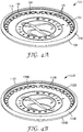
- FIG. 4A shows a perspective view of a first embodiment of the diaphragm 100 and
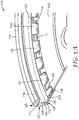
- FIG. 5A shows an enlarged view of a portion of the first embodiment of the diaphragm 100.
- FIG. 4B shows a perspective view of a second embodiment of the diaphragm 100B and
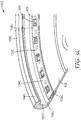
- FIG. 5B shows an enlarged view of a portion of the second embodiment of the diaphragm 100B.
- the second embodiment of the diaphragm 100B has many reference characters similar to the reference characters used to describe elements of the first embodiment of the diaphragm 100 except that the reference character "B" has been added. The elements otherwise function similarly.
- the diaphragm 100, 100B includes a disc 102, 102B and a rim 104, 104B.
- the disc 102, 102B and the rim 104, 104B are made from different materials but can be a unitary piece when fabricated.
- the disc 102, 102B and the rim 104, 104B are made of the same material.
- the disc 102, 102B may be formed of any material which is known in the art as being suitable for use as a diaphragm disc. Examples of suitable materials include plastics such as polyester, fiberglass-reinforced plastics, polycarbonates, carbon fiber composites, polystyrene and metals such as stainless steel.
- a suitable thickness for the disc 102, 102B is about 0.005 to about 0.020 inches (127 to 508 micrometer) and particularly about 0.010 to about 0.012 inches (254 to 305 micrometer). In one embodiment, the disc 102, 102B is a 0.010 inches thick (254 micrometer-thick) epoxy resin-fiberglass laminate.
- the disc 102 includes a plurality of apertures 106 along the periphery of the disc 102.
- the apertures 106 aid in maintaining the disc 102 to the rim 104 during molding and long term use of the diaphragm 100.
- the disc 102 is placed in the diaphragm rim die tool (for example an injection mold).
- the material used for the rim is then melt molded (for example injection molded) around the edge of the diaphragm disc to form a unitary single piece diaphragm which includes the rim.
- FIGS. 4A and 5A show the disc 102 as having a plurality of apertures 106
- the disc 102 may include any number of apertures 106, including only one, along a periphery of the disc 102 without departing from the intended scope of the present invention.
- the diaphragm 100B does not include any apertures in the disc 102B.
- the rim 104, 104B includes a wall 108, 108B having a first end 110, 110B and a second end 112, 112B, a lip 114, 114B extending substantially perpendicularly from the first end 110, 110B of the wall 108, 108B, a bridge 116, 116B extending substantially perpendicularly from the second end 112, 112B of the wall 108, 108B, and a fork 118, 118B extending from the bridge 116, 116B.
- the wall 108, 108B has a circular or ring-shaped configuration and functions to maintain the diaphragm 100, 100B on the chestpiece 12.
- the wall 108, 108B has an inner side 120, 120B and an opposite outer side 122, 122B, a patient facing edge 124, 124B and an opposite chestpiece facing edge 126, 126B.
- the wall 108, 108B must be thick enough to have sufficient rigidity to stay on the chestpiece 12. If the wall 108, 108B is too thick, the diaphragm 100, 100B may fall off of the chestpiece 12 ( FIG. 1 ) when a small amount of pressure is applied.
- the wall 108, 108B is important in determining the height of the disc 102, 102B above the chestpiece 12, which in turn affects tunability of the chestpiece 12.
- the lip 114, 114B extends from the inner side 120, 120B at the first end 110, 110B of the wall 108, 108B at the chestpiece facing edge 126, 126B and functions to secure the diaphragm 100, 100B to the chestpiece 12.
- the chestpiece 12 is inserted between the lip 114, 114B and the fork 118, 118B of the rim 104, 104B.
- the lip 114, 114B must hold the diaphragm 100, 100B tightly enough to stay on the chestpiece 12, but not so tight such that the diaphragm 100, 100B cannot be removed if desired, for example, for cleaning.
- the bridge 116, 116B extends from the inner side 120, 120B of the second end 112, 112B of the wall 108, 108B at the patient facing edge 124, 124B.
- the bridge 116, 116B, and particularly the bridge height and thickness, allows the diaphragm 100, 100B to have sufficient flexibility to move and achieve good acoustics.
- the bridge height needs to be as thin as possible while minimizing the risk of the rim 104, 104B breaking during normal use.
- the bridge width should be as long as possible between the chestpiece outer diameter contact surface and the disc while still allowing filling during molding.
- the fork 118, 118B extends from the bridge 116, 116B and functions to secure the disc 102, 102B within the rim 104, 104B and includes an inner flange 128, 128B and an outer flange 130, 130B substantially perpendicular to the inner flange 128, 128B.
- the disc 102, 102B is positioned between the inner and outer flanges 128, 128B and 130, 130B, where it is maintained within the rim 104, 104B.
- the fork flanges 128, 128B and 130, 130B need to be thick enough to allow filling on both sides of the disc 102, 102B during the molding process.
- the inner flange 128, 128B includes a plurality of features 132, 132B.
- the features 132, 132B are substantially equally spaced apart from one another and may form a pattern along the entire internal circumference of the rim 104, 104B.
- the features 132, 132B are positioned randomly around the inner circumference of the rim 104, 104B.
- the rim 104, 104B may include any number of features 132, 132B without departing from the intended scope of the present invention.
- the inner flange 128, 128B includes at least two features 132, 132B and particularly at least three features 132, 132B.
- the features 132, 132B of the present invention would include between about 5 and about 95% of the area A, particularly between about 15 and about 85% of the area A, and more particularly between about 25 and about 75% of the area A.
- the features 132, 132B extend from the bridge 116, 166B at a distance sufficient to hold the disc 102, 102B to the rim 104, 104B. In one embodiment, the features 132, 132B extend between about 0.02 inches (.051 millimeters) to about 0.15 inches (3.81 millimeters) from the bridge 116, 116B.
- the features 132, 132B may be manufactured by any means known in the art. Although figures 4A and 5A and 4B and 5B depict the features 132, 132B as having a tooth shape, the features 132, 132B may take any shape without departing from the intended scope of the present invention.
- the features 132, 132B may be circular, triangular, pyramids, elliptical or any other shape.
- differently shaped features may be used in combination and do not all need to be the same on a particular diaphragm.
- the features 132 when the disc 102 includes apertures 106, the features 132 must extend from the bridge 116 at least to the apertures 106 of the disc 102. In one embodiment, because the rim 104 may not have good adhesion qualities to the disc 102, the features 132 provide a mechanical bond through the disc 102. This is accomplished in conjunction with the plurality of apertures 106 around the outer diameter of the disc 102. The pitch on the apertures 106 and features 132 is such that no matter where the disc 102 is placed in the rim 104 radially, at least one or parts of two apertures 106 line up with the features 132. This can be seen in FIGS. 4A and 5A . The alignment of the apertures 106 and features 132 allows a mechanical bond through each of the features 132 as described above.
- apertures are not needed in the disc. This embodiment is shown, for example, in FIGS. 4B and 5B .
- FIG. 5C shows an enlarged view of a portion of a third embodiment of the diaphragm 100C of the present invention.
- the third embodiment of the diaphragm 100C has many reference characters similar to the reference characters used to describe elements of the first embodiment of the diaphragm 100 except that the reference character "C" has been added. The elements otherwise function similarly.
- the features 132, 132B extend individually from the bridge 116, 116B.
- the inner flange 128C includes a plurality of holes 200 with the features 132C formed in between each of the holes 200.
- the holes 200 may be any shape, such as circular, triangular or irregular in shape without departing from the intended scope of the present invention.
- the plurality of holes 200 may be equidistant from each other around the periphery of the disc 102C. In other embodiments, the plurality of holes 200 may be randomly spaced from each other.
- the features 132C include between about 5 and about 95% of the inner flange 128C, particularly between about 15 and about 85% of the inner flange 128C, and more particularly between about 25 and about 75% of the inner flange 128C.
- the features 132C in the third embodiment of the diaphragm 100C function similarly to the features 132 of the first embodiment of the diaphragm 100 shown in FIGS. 4A and 5A .
- the pitch on the apertures 106 and the features 132C should be such that no matter where the disc 102 is placed in the rim 104C radially, at least one or parts of two apertures 106 line up with the features 132C.
- the diaphragm Upon assembly onto the chestpiece, the diaphragm must have enough flexibility to allow the diaphragm to be easily positioned on, and removed from, the chestpiece and rigid enough to ensure that the diaphragm does not unintentionally fall off of the chestpiece.
- the rim has a Shore A durometer hardness of between about 40 and about 110, particularly between about 70 and about 90 and more particularly between about 75 and 85.
Landscapes
- Health & Medical Sciences (AREA)
- Life Sciences & Earth Sciences (AREA)
- Molecular Biology (AREA)
- Surgery (AREA)
- Engineering & Computer Science (AREA)
- Biomedical Technology (AREA)
- Heart & Thoracic Surgery (AREA)
- Medical Informatics (AREA)
- Physics & Mathematics (AREA)
- Acoustics & Sound (AREA)
- Animal Behavior & Ethology (AREA)
- General Health & Medical Sciences (AREA)
- Public Health (AREA)
- Veterinary Medicine (AREA)
- Percussion Or Vibration Massage (AREA)
- Diaphragms And Bellows (AREA)
- Surgical Instruments (AREA)
Description
- The present invention is related generally to the field of stethoscopes. In particular, the present invention is related to stethoscope diaphragms having a series of features.
- Complete diagnosis of a patient using a stethoscope often requires that a physician monitor low frequency and high frequency sounds associated with, for example, the heart. With respect to the heart, it is important that the physician alternate between the monitoring of low frequency and high frequency sounds so that the physician does not lose the impression from the previously heard heartbeat before the next beat is heard. Without the benefit of tunable technology, the clinician would be required to turn the chestpiece over to hear additional sounds. The diaphragms currently used on most stethoscopes include two pieces, the diaphragm and the rim. These pieces may be manufactured as two separate pieces or as a single, unitary piece. The rim is used to hold the diaphragm on the chestpiece.
- The present invention, and preferred embodiments thereof, is defined in independent claim 1 and dependent claims 2 - 9 and relates to a stethoscope diaphragm including a disc and a rim. The rim includes a wall having a first end and a second end; a lip extending substantially perpendicularly from the first end of the wall; a bridge extending substantially perpendicularly from the second end of the wall; a fork extending from the bridge, wherein the fork includes an inner flange and an outer flange; and a plurality of features extending from the inner flange.
- These figures are not drawn to scale and are intended merely for illustrative purposes.
-
FIG. 1 is a schematic view of a stethoscope using a diaphragm according to the present invention. -
FIG. 2 is an enlarged, exploded, partial sectional view of a chestpiece of the stethoscope ofFIG. 1 . -
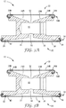
FIG. 3A is a cross-sectional view of an assembled chestpiece showing a diaphragm of the present invention in an outer position. -
FIG. 3B is a cross-sectional view of an assembled chestpiece showing a diaphragm of the present invention in an inner position. -
FIG. 4A is a perspective view of a first embodiment of a diaphragm of the present invention. -
FIG. 4B is a perspective view of a second embodiment of a diaphragm of the present invention. -
FIG. 5A is an enlarged view of a portion of the first embodiment of the diaphragm of the present invention shown inFIG. 4A . -
FIG. 5B is an enlarged view of a portion of the second embodiment of the diaphragm of the present invention shown inFIG. 4B . -
FIG. 5C is an enlarged view of a portion of a third embodiment of a diaphragm of the present invention. - The present invention is a diaphragm to be used with stethoscopes. In one embodiment, the stethoscopes are tunable stethoscopes. The diaphragm includes a disc and a rim. The rim includes a plurality of features extending from the inner circumference of the rim which surrounds the underside of the disc. The plurality of features adds support to the disc and provides a uniform part. In addition, the diaphragm including the rim having the plurality of features allows for the diaphragm to be manufactured with a decreased number of defects.
- As used in the instant specification and claims, "acoustical stiffness" of the diaphragm designates the mechanical stiffness of the diaphragm as influenced by the mechanical stiffness of the diaphragm material itself, the thickness of the diaphragm, the shape of the diaphragm, the diameter of the diaphragm, and the manner in which the diaphragm is attached to the stethoscope head. The phrase "plane of the diaphragm" refers to the generally planar surface of the diaphragm (disc).
- As used in the instant specification and claims, the phrase "suspended diaphragm" designates a diaphragm having at least a suspension member as described below. The diaphragm and suspension member are operatively associated with an immobilization means as described below. For example, the suspended diaphragm may be constructed according to the teachings of
U.S. Pat. No. 4,440,258 to Packard . A stethoscope diaphragm according to the preamble of independent claim 1 is known from prior art documentUS 6,378,648 . - Referring first to
FIG. 1 , astethoscope 10 includes achestpiece 12 formed of conventional material utilized in the fabrication of stethoscope chestpieces, for example, metals such as stainless steel and aluminum, metallic composites, plastic and wood. Thechestpiece 12 is attached to a conventional headset such as that described inU.S. Pat. No. 4,200,169 which includes an elongatedflexible tubing 14 that splits intoflexible tubings 16 that run toear tips 18. The lower end of theflexible tubing 14 is adapted to be coupled to a conventional stem fitting on thechestpiece 12. The coupling may utilize the indexing detent as taught inU.S. Pat. No. 4,770,270 . Binaural tubes for stethoscopes can be prepared in accordance with the teachings ofU.S. Pat. Nos. 5,111,904 ;5,380,182 ; and5,324,471 to Packard et al. - The
ear tips 18 are sized and shaped to engage the surfaces of the user's ears. Theear tips 18 may include any suitable ear tips. In one embodiment, theear tips 18 include the soft ear tips disclosed inU.S. Pat. Nos. 4,852,684 ;4,913,259 and5,449,865 . - Referring to one embodiment shown in
FIGS. 2 ,3A and 3B , thechestpiece 12 is a dual-sided chestpiece including a firstsound collecting side 20 and a secondsound collecting side 22. It should be noted that although the diaphragm of the present invention is discussed with respect to a dual-sided chestpiece, the diaphragm may also be used with a single-sided chestpiece without limiting the scope of the present invention. In one embodiment, thestethoscope 10 affords tuning in of sound while using either thefirst side 20 or thesecond side 22 of thechestpiece 12. The firstsound collecting side 20 is sized and shaped to collect sounds from adult patients. The secondsound collecting side 22 is sized and shaped to afford sufficient surface contact on pediatric or thin patients. The secondsound collecting side 22 is also substantially smaller than the first sound collecting side to afford easier access to remote or difficult to reach locations. - The first
sound collecting side 20 has afirst recess 24 with an innermostcentral portion 26, anouter rim portion 28, and anacoustic channel central portion 26. Afirst diaphragm 34 is also located on the firstsound collecting side 20. Thefirst diaphragm 34 includes arim 36 anddisc 38 positioned within therim 36, together having a peripheral edge portion and a predetermined surface contour overlying at least a portion of thefirst recess 24. As shown inFIGS. 3A and 3B , thefirst diaphragm 34 is moveably connected to or "operatively associated" with theouter rim portion 28 of thefirst recess 24. - The
first diaphragm 34 is positioned on thechestpiece 12 such that there can be movement of thefirst diaphragm 34 in a direction substantially perpendicular to the plane of thefirst diaphragm 34 between: 1) a normal outer position to which thefirst diaphragm 34 is biased and 2) an inner position more closely adjacent the central portion of thefirst recess 24. This movement is accomplished without substantially changing the surface contour of or the lateral tension in thefirst diaphragm 34. - A first immobilizing means 40 is situated on the first
sound collecting side 20 of thechestpiece 12. The first immobilizing means 40 is located within thefirst recess 24. Together with the central portion of thefirst recess 24, the first immobilizing means 40 forms a shallow recess within thefirst recess 24. The immobilizing means 40 is sized and shaped to be contacted by thefirst diaphragm 34. InFIG. 3B , it is thefirst diaphragm 34 which contacts the immobilizing means 40. When thefirst diaphragm 34 is in the inner position, the immobilizing means 40 immobilizes thefirst diaphragm 34. - The first
sound collecting side 20 of thechestpiece 12 will pass low frequency (bass) sounds and gradually attenuate sounds with higher frequencies when thefirst diaphragm 34 is in the outer position and between the outer and inner positions. When thefirst diaphragm 34 is in the inner position, the acoustical stiffness of thefirst diaphragm 34 will be significantly higher than the acoustical stiffness of thefirst diaphragm 34 when it is in the outer position, so that the firstsound collecting side 20 of thechestpiece 12 will attenuate or block low frequency sounds while leaving higher frequency sounds unchanged. In use, a physician would simply modify the manual pressure exerted on thechestpiece 12 in order to switch between the outer and inner positions. In one embodiment, the level of bass attenuation varies from about 3 to about 21 dB. - The second
sound collecting side 22 is adapted to include a second suspended diaphragm. The secondsound collecting side 22 has many reference characters similar to the reference characters used to describe elements of the firstsound collecting side 20 except that the reference character "B" has been added. The secondsound collecting side 22 has asecond recess 24B with an innermostcentral portion 26B, anouter rim portion 28B, and anacoustic channel 30, 32' communicating with thecentral portion 26B. The secondsound collecting side 22 has asecond diaphragm 34B including arim 36B anddisc 38B positioned within therim 36B, together having with a peripheral edge portion and a predetermined surface contour overlying at least a portion of thesecond recess 24B. Thesecond diaphragm 34B is moveably associated with theouter rim portion 28B of thesecond recess 24B. - A second immobilizing means 40B is situated on the second
sound collecting side 22 of thechestpiece 12. The second immobilizing means 40B is located within thesecond recess 24B. Together with thecentral portion 26B of thesecond recess 24B, the second immobilizing means 40B forms a shallow recess within thesecond recess 24B. The second immobilizing means 40B is sized and shaped to be contacted by thesecond diaphragm 34B. When thesecond diaphragm 34B is in the inner position, the second immobilizing means 40B immobilizes thesecond diaphragm 34B. - The second
sound collecting side 22 of thechestpiece 12 will pass low frequency sounds and gradually attenuate sounds with higher frequencies when thesecond diaphragm 34B is in the outer position and between the outer and inner positions. When thesecond diaphragm 34B is in the inner position, the acoustical stiffness of thesecond diaphragm 34B will be significantly higher than its first acoustical stiffness so that the secondsound collecting side 22 of thechestpiece 12 will attenuate or block low frequency sounds while leaving higher frequency sounds unchanged. In one embodiment, the level of bass attenuation varies from about 3 to about 21 dB. - The size and shape of the first
sound collecting side 20 is different than the size and shape of the secondsound collecting side 22. - In one embodiment, the immobilizing means 40 and 40B include ridges machined into the metal of the chestpiece 12 (see
FIGS. 3A and 3B ). Other immobilizing means which are suitable for employment in the stethoscope heads of the present invention include O-rings, molded ridges, and inserts (e.g., plastic inserts). For example, themachined ridge 40B may have an inner diameter of about 1.053 inches, a depth radius of about 0.016 inches (0.41 millimeters), and a width of 0.015 inches (0.38 millimeters). - The
diaphragms respective recesses rims discs diaphragms diaphragms rim diaphragms - The response of
chestpiece 12 to low frequency and high frequency sounds is affected by several parameters. The thickness of the diaphragm affects the response, and suitable thicknesses for the diaphragms have been discussed hereinabove. Also, the relative dimensions of first recess and second recess affect the response. The following have been found to be suitable dimensions for therecess 24B: therecess 24B has a diameter of about 1.32 inches (3.35 centimeters), a major radius as seen inFIGS. 3A and 3B of about 0.196 inches (4.98 millimeters), an initial major depth of about 0.22 inches (5.6 millimeters) and a secondary depth of about 0.235 inches (5.97 millimeters). The passage 32' has a diameter of about 0.125 inches (3.175 millimeters). - It is contemplated that the acoustical stiffness of the diaphragm can be increased suitably by contact of the suspension member with the immobilizing means.
- Turning now to
FIGS. 4A and5A and4B and5B , first and second embodiments, respectively, of thediaphragm FIG. 4A shows a perspective view of a first embodiment of thediaphragm 100 andFIG. 5A shows an enlarged view of a portion of the first embodiment of thediaphragm 100.FIG. 4B shows a perspective view of a second embodiment of thediaphragm 100B andFIG. 5B shows an enlarged view of a portion of the second embodiment of thediaphragm 100B. The second embodiment of thediaphragm 100B has many reference characters similar to the reference characters used to describe elements of the first embodiment of thediaphragm 100 except that the reference character "B" has been added. The elements otherwise function similarly. As mentioned above, thediaphragm disc rim disc rim disc rim - The
disc disc disc - In the first embodiment of the
diaphragm 100 shown inFIGS. 4A and5A , thedisc 102 includes a plurality ofapertures 106 along the periphery of thedisc 102. Theapertures 106 aid in maintaining thedisc 102 to therim 104 during molding and long term use of thediaphragm 100. In the unitary molding process, thedisc 102 is placed in the diaphragm rim die tool (for example an injection mold). The material used for the rim is then melt molded (for example injection molded) around the edge of the diaphragm disc to form a unitary single piece diaphragm which includes the rim. - Although
FIGS. 4A and5A show thedisc 102 as having a plurality ofapertures 106, thedisc 102 may include any number ofapertures 106, including only one, along a periphery of thedisc 102 without departing from the intended scope of the present invention. In the second embodiment shown inFIGS. 4B and5B , thediaphragm 100B does not include any apertures in thedisc 102B. - Looking particularly at
FIGS. 5A and5B , therim wall first end second end lip first end wall bridge second end wall fork bridge - The
wall diaphragm chestpiece 12. Thewall inner side outer side patient facing edge chestpiece facing edge wall chestpiece 12. If thewall diaphragm FIG. 1 ) when a small amount of pressure is applied. For example, if the wall is too thick, when the chestpiece rubs on clothing, such as when a health care provider removes the chestpiece from a pocket, the diaphragm may unintentionally fall off of the chestpiece. The height of thewall disc chestpiece 12, which in turn affects tunability of thechestpiece 12. - The
lip inner side first end wall chestpiece facing edge diaphragm chestpiece 12. When assembled, thechestpiece 12 is inserted between thelip fork rim lip diaphragm chestpiece 12, but not so tight such that thediaphragm - The
bridge inner side second end wall patient facing edge bridge diaphragm rim - The
fork bridge disc rim inner flange outer flange inner flange disc outer flanges rim disc - As can be seen in
FIGS. 5A and5B , theinner flange features features rim features rim rim features inner flange features features inner flange bridge features - The
features bridge 116, 166B at a distance sufficient to hold thedisc rim features bridge - The
features figures 4A and5A and4B and5B depict thefeatures features features - Turning back to
FIGS. 4A and5A , when thedisc 102 includesapertures 106, thefeatures 132 must extend from thebridge 116 at least to theapertures 106 of thedisc 102. In one embodiment, because therim 104 may not have good adhesion qualities to thedisc 102, thefeatures 132 provide a mechanical bond through thedisc 102. This is accomplished in conjunction with the plurality ofapertures 106 around the outer diameter of thedisc 102. The pitch on theapertures 106 and features 132 is such that no matter where thedisc 102 is placed in therim 104 radially, at least one or parts of twoapertures 106 line up with thefeatures 132. This can be seen inFIGS. 4A and5A . The alignment of theapertures 106 and features 132 allows a mechanical bond through each of thefeatures 132 as described above. - In some embodiments, apertures are not needed in the disc. This embodiment is shown, for example, in
FIGS. 4B and5B . -
FIG. 5C shows an enlarged view of a portion of a third embodiment of the diaphragm 100C of the present invention. The third embodiment of the diaphragm 100C has many reference characters similar to the reference characters used to describe elements of the first embodiment of thediaphragm 100 except that the reference character "C" has been added. The elements otherwise function similarly. In the embodiments shown and described inFIGS. 4A and5A and4B and5B , thefeatures bridge FIG. 5C , the inner flange 128C includes a plurality ofholes 200 with thefeatures 132C formed in between each of theholes 200. AlthoughFIG. 5C depicts theholes 200 as having a square shape, theholes 200 may be any shape, such as circular, triangular or irregular in shape without departing from the intended scope of the present invention. In one embodiment, the plurality ofholes 200 may be equidistant from each other around the periphery of the disc 102C. In other embodiments, the plurality ofholes 200 may be randomly spaced from each other. In one embodiment, thefeatures 132C include between about 5 and about 95% of the inner flange 128C, particularly between about 15 and about 85% of the inner flange 128C, and more particularly between about 25 and about 75% of the inner flange 128C. Thefeatures 132C in the third embodiment of the diaphragm 100C function similarly to thefeatures 132 of the first embodiment of thediaphragm 100 shown inFIGS. 4A and5A . Thus, when the disc 102C includesapertures 106, the pitch on theapertures 106 and thefeatures 132C should be such that no matter where thedisc 102 is placed in therim 104C radially, at least one or parts of twoapertures 106 line up with thefeatures 132C. - Upon assembly onto the chestpiece, the diaphragm must have enough flexibility to allow the diaphragm to be easily positioned on, and removed from, the chestpiece and rigid enough to ensure that the diaphragm does not unintentionally fall off of the chestpiece. In one embodiment, the rim has a Shore A durometer hardness of between about 40 and about 110, particularly between about 70 and about 90 and more particularly between about 75 and 85.
- Although the present invention has been described with reference to preferred embodiments, workers skilled in the art will recognize that changes may be made in form and detail without departing from the scope of the invention.
Claims (9)
- A stethoscope diaphragm (100) comprising:a disc (102); anda rim (104), wherein the rim comprises:a wall (108) having a first end and a second end (110, 112);a lip (114) extending substantially perpendicularly from the first end (110) of the wall (108);a bridge (116) extending substantially perpendicularly from the second end (112) of the wall (108);a fork (118) extending from the bridge (116), wherein the fork includes an inner flange (128) and an outer flange (130) wherein the disc is positioned between said inner and outer flanges, where it is maintained within the rim;
characterised in that the rim further comprisesa plurality of features (132) extending radially inward from the inner flange, wherein said features are spaced apart from one another and are configured to hold and add support to the disc. - The stethoscope diaphragm of claim 1, wherein the plurality of features (132) are spaced substantially equally around the inner flange (128).
- The stethoscope diaphragm of claim 1, comprising at least three features (132).
- The stethoscope diaphragm of claim 1, wherein the disc (102) has a plurality of apertures (106) around an outer periphery of a face of the disc.
- The stethoscope diaphragm of claim 4, wherein the plurality of apertures (106) are offset from the plurality of features (132).
- The stethoscope diaphragm of claim 1, wherein the features (132) have a length of between about 0.5 and about 3.8 millimeters.
- The stethoscope diaphragm of claim 1, wherein the features (132) are formed from holes cut out from the inner flange.
- The stethoscope diaphragm of claim 7, wherein the features (132) comprise between about 5 and about 95% of the inner flange.
- The stethoscope diaphragm of claim 1, wherein the disc (102) and the rim (104) are a unitary piece.
Applications Claiming Priority (2)
| Application Number | Priority Date | Filing Date | Title |
|---|---|---|---|
| US201562105898P | 2015-01-21 | 2015-01-21 | |
| PCT/US2016/012945 WO2016118356A1 (en) | 2015-01-21 | 2016-01-12 | Stethoscope diaphragm |
Publications (3)
| Publication Number | Publication Date |
|---|---|
| EP3247278A1 EP3247278A1 (en) | 2017-11-29 |
| EP3247278A4 EP3247278A4 (en) | 2018-08-15 |
| EP3247278B1 true EP3247278B1 (en) | 2021-02-24 |
Family
ID=56417594
Family Applications (1)
| Application Number | Title | Priority Date | Filing Date |
|---|---|---|---|
| EP16740512.5A Active EP3247278B1 (en) | 2015-01-21 | 2016-01-12 | Stethoscope diaphragm |
Country Status (6)
| Country | Link |
|---|---|
| US (1) | US10213181B2 (en) |
| EP (1) | EP3247278B1 (en) |
| JP (1) | JP6425823B2 (en) |
| CN (1) | CN107205717B (en) |
| BR (1) | BR112017015697A2 (en) |
| WO (1) | WO2016118356A1 (en) |
Families Citing this family (7)
| Publication number | Priority date | Publication date | Assignee | Title |
|---|---|---|---|---|
| USD877327S1 (en) * | 2018-10-03 | 2020-03-03 | Donald Lynn Loriaux | Stethoscope diaphraghm |
| WO2020072561A1 (en) | 2018-10-05 | 2020-04-09 | 3M Innovative Properties Company | Metal injection molding for stethoscope chestpiece |
| US11766822B2 (en) | 2019-08-20 | 2023-09-26 | 3M Innovative Properties Company | Microstructured surface with increased microorganism removal when cleaned, articles and methods |
| US12434427B2 (en) | 2019-08-20 | 2025-10-07 | Solventum Intellectual Properties Company | Microstructured surface with increased microorganism removal when cleaned, articles and methods |
| WO2021236429A1 (en) | 2020-05-20 | 2021-11-25 | 3M Innovative Properties Company | Medical articles with microstructured surface |
| JP2023553925A (en) | 2020-12-11 | 2023-12-26 | スリーエム イノベイティブ プロパティズ カンパニー | Methods and articles for thermoforming films with structured surfaces |
| US11890130B2 (en) * | 2022-06-01 | 2024-02-06 | Jazz Hipster Corporation | Pickup diaphragm |
Family Cites Families (36)
| Publication number | Priority date | Publication date | Assignee | Title |
|---|---|---|---|---|
| US4200169A (en) | 1978-10-16 | 1980-04-29 | Minnesota Mining And Manufacturing Company | Stethoscope |
| US4461368A (en) * | 1982-04-15 | 1984-07-24 | Plourde R Gilles | Diaphragm cover for a stethoscope |
| US4440258A (en) | 1982-05-12 | 1984-04-03 | Minnesota Mining & Manufacturing Company | Tunable stethoscope |
| US4475619B1 (en) * | 1983-03-24 | 1994-05-10 | Minnesota Mining & Mfg | Stethoscope with floating diaphragm |
| US4770270A (en) | 1987-05-13 | 1988-09-13 | Minnesota Mining And Manufacturing Company | Stethoscope chestpiece with a sound conveying indexing detent |
| US4913259A (en) | 1987-12-16 | 1990-04-03 | Minnesota Mining And Manufacturing Company | Compressible ear tip |
| US4852684A (en) | 1987-12-16 | 1989-08-01 | Minnesota Mining And Manufacturing Company | Compressible ear tip |
| US5111904A (en) | 1989-06-02 | 1992-05-12 | Minnesota Mining And Manufacturing Company | Molded article having elastomeric mold member used therewith |
| US4995473A (en) * | 1989-12-21 | 1991-02-26 | Minnesota Mining And Manufacturing Company | Stethoscope with diaphragm head adapter |
| US5932849A (en) * | 1992-11-13 | 1999-08-03 | Minnesota Mining And Manufacturing Company | Stethoscope having microphone therein |
| US5389747A (en) * | 1993-08-16 | 1995-02-14 | Mohrin; Carl M. | Stethoscope |
| US5449865A (en) | 1994-01-28 | 1995-09-12 | Minnesota Mining And Manufacturing Company | Ear tips having molded-in recesses for attachment to a stethoscope |
| FR2738141B1 (en) * | 1995-08-29 | 1998-01-02 | Boussignac Georges | BIAURICULAR STETHOSCOPE WITH ENVIRONMENTAL LISTENING |
| US5747752A (en) * | 1997-01-30 | 1998-05-05 | Graham-Field, Inc. | Stethoscope with disposable chestpiece |
| US6206134B1 (en) * | 1997-03-08 | 2001-03-27 | Wayne T. Stark | Cover for stethoscope head |
| CH691757A5 (en) * | 1997-05-13 | 2001-10-15 | Artemio Granzotto | Stethoscope head. |
| GB2327353A (en) * | 1997-07-22 | 1999-01-27 | Shieh Woei Kang | A Switch-Frequency Stethoscope |
| US5945640A (en) * | 1997-08-01 | 1999-08-31 | 3M Innovative Properties Company | Stethoscope chestpiece having two suspended diaphragms |
| US5931792A (en) * | 1997-11-06 | 1999-08-03 | 3M Innovative Properties Company | Stethoscope chestpiece |
| US5910992A (en) * | 1998-01-21 | 1999-06-08 | Ho; Chi-Sheng | Stethoscope with an indexing detent |
| US6019187A (en) * | 1998-03-13 | 2000-02-01 | Appavu; Aramudhan S. | Disposable stethoscope cover diaphragm |
| US5921941A (en) | 1998-07-17 | 1999-07-13 | Longobardo; John J. | Disposable stethoscope cover |
| US6378648B1 (en) * | 2000-03-06 | 2002-04-30 | Marc S. Werblud | Diaphragm assembly for stethoscope chest piece |
| US6523639B1 (en) | 2002-09-05 | 2003-02-25 | Woei-Kang Shieh | Receiver structure of stethoscope |
| US7424929B1 (en) * | 2005-09-22 | 2008-09-16 | Stethocap, Inc. | Cover for a bell or a diaphragm of a stethoscope |
| US7757807B1 (en) * | 2005-09-22 | 2010-07-20 | Stethocap, Inc. | Cover for a bell or a diaphragm of a stethoscope |
| US8396228B2 (en) * | 2008-02-27 | 2013-03-12 | Stethoscope Technologies, Inc. | Floating ballast mass active stethoscope or sound pickup device |
| CN201409932Y (en) * | 2009-04-27 | 2010-02-24 | 单希杰 | High-elasticity deformable composite membrane |
| CN201409933Y (en) * | 2009-04-27 | 2010-02-24 | 单希杰 | Matching structure of membrane and listening head body of two-band stethoscope |
| CN201481445U (en) * | 2009-09-03 | 2010-05-26 | 单希杰 | Complex film sheet, listening head matched with the complex film sheet, and matching structure of the complex film sheet and the listening head |
| CN103315768B (en) * | 2012-03-19 | 2014-11-05 | 无锡市凯顺医疗器械制造有限公司 | Structural component for fixing auscultator head and fixing part |
| CN203354564U (en) * | 2013-03-21 | 2013-12-25 | 无锡市凯顺医疗器械制造有限公司 | Composite stethoscope membrane assembly |
| CN103156635A (en) * | 2013-03-21 | 2013-06-19 | 无锡市凯顺医疗器械制造有限公司 | Combined-type stethoscope membrane assembly |
| CN203244411U (en) * | 2013-05-07 | 2013-10-23 | 鹿得医疗器械(南通)有限公司 | Novel frequency conversion membrane structure |
| US9770307B2 (en) * | 2013-06-21 | 2017-09-26 | Jon Krupnick | Cover assembly for a stethoscope and a dispenser kit |
| WO2016022380A2 (en) * | 2014-08-04 | 2016-02-11 | 3M Innovative Properties Company | One piece stethoscope diaphragm |
-
2016
- 2016-01-12 EP EP16740512.5A patent/EP3247278B1/en active Active
- 2016-01-12 WO PCT/US2016/012945 patent/WO2016118356A1/en not_active Ceased
- 2016-01-12 CN CN201680006725.9A patent/CN107205717B/en active Active
- 2016-01-12 JP JP2017538214A patent/JP6425823B2/en not_active Expired - Fee Related
- 2016-01-12 US US15/544,304 patent/US10213181B2/en active Active
- 2016-01-12 BR BR112017015697A patent/BR112017015697A2/en not_active Application Discontinuation
Non-Patent Citations (1)
| Title |
|---|
| None * |
Also Published As
| Publication number | Publication date |
|---|---|
| CN107205717B (en) | 2020-09-15 |
| CN107205717A (en) | 2017-09-26 |
| US20180008227A1 (en) | 2018-01-11 |
| BR112017015697A2 (en) | 2018-03-20 |
| WO2016118356A1 (en) | 2016-07-28 |
| EP3247278A4 (en) | 2018-08-15 |
| JP6425823B2 (en) | 2018-11-21 |
| US10213181B2 (en) | 2019-02-26 |
| EP3247278A1 (en) | 2017-11-29 |
| JP2018506336A (en) | 2018-03-08 |
Similar Documents
| Publication | Publication Date | Title |
|---|---|---|
| US10213181B2 (en) | Stethoscope diaphragm | |
| EP3177211B1 (en) | One piece stethoscope diaphragm | |
| CA1192844A (en) | Tunable stethoscope | |
| EP0434310B1 (en) | Stethoscope with diaphragm head adapter | |
| US5945640A (en) | Stethoscope chestpiece having two suspended diaphragms | |
| US5826582A (en) | Ear phone assembly for use with a hearing screener | |
| US7198133B2 (en) | Ear coupler | |
| US5913309A (en) | Disposable element for use with a hearing screener | |
| US20040226771A1 (en) | Stethoscope | |
| US6019186A (en) | Disposable stethoscope assembly | |
| JPH0324214B2 (en) | ||
| US20200187894A1 (en) | Diaphragm, Methods for Manufacturing Same and Stethoscope Provided with Same | |
| JP2008541676A (en) | Hearing aid hook | |
| US20220061795A1 (en) | Stethoscope chestpiece with multiple cavities | |
| USD1101188S1 (en) | Instrument and utensil for medical or laboratory diagnosis | |
| WO2000071029A1 (en) | Disposable stethoscope assembly | |
| WO2023162992A1 (en) | Chest piece and stethoscope |
Legal Events
| Date | Code | Title | Description |
|---|---|---|---|
| STAA | Information on the status of an ep patent application or granted ep patent |
Free format text: STATUS: THE INTERNATIONAL PUBLICATION HAS BEEN MADE |
|
| PUAI | Public reference made under article 153(3) epc to a published international application that has entered the european phase |
Free format text: ORIGINAL CODE: 0009012 |
|
| STAA | Information on the status of an ep patent application or granted ep patent |
Free format text: STATUS: REQUEST FOR EXAMINATION WAS MADE |
|
| 17P | Request for examination filed |
Effective date: 20170724 |
|
| AK | Designated contracting states |
Kind code of ref document: A1 Designated state(s): AL AT BE BG CH CY CZ DE DK EE ES FI FR GB GR HR HU IE IS IT LI LT LU LV MC MK MT NL NO PL PT RO RS SE SI SK SM TR |
|
| AX | Request for extension of the european patent |
Extension state: BA ME |
|
| DAV | Request for validation of the european patent (deleted) | ||
| DAX | Request for extension of the european patent (deleted) | ||
| A4 | Supplementary search report drawn up and despatched |
Effective date: 20180712 |
|
| RIC1 | Information provided on ipc code assigned before grant |
Ipc: A61B 7/04 20060101ALI20180706BHEP Ipc: A61B 7/02 20060101AFI20180706BHEP |
|
| GRAP | Despatch of communication of intention to grant a patent |
Free format text: ORIGINAL CODE: EPIDOSNIGR1 |
|
| STAA | Information on the status of an ep patent application or granted ep patent |
Free format text: STATUS: GRANT OF PATENT IS INTENDED |
|
| INTG | Intention to grant announced |
Effective date: 20200731 |
|
| GRAS | Grant fee paid |
Free format text: ORIGINAL CODE: EPIDOSNIGR3 |
|
| GRAA | (expected) grant |
Free format text: ORIGINAL CODE: 0009210 |
|
| STAA | Information on the status of an ep patent application or granted ep patent |
Free format text: STATUS: THE PATENT HAS BEEN GRANTED |
|
| AK | Designated contracting states |
Kind code of ref document: B1 Designated state(s): AL AT BE BG CH CY CZ DE DK EE ES FI FR GB GR HR HU IE IS IT LI LT LU LV MC MK MT NL NO PL PT RO RS SE SI SK SM TR |
|
| REG | Reference to a national code |
Ref country code: CH Ref legal event code: EP |
|
| REG | Reference to a national code |
Ref country code: DE Ref legal event code: R096 Ref document number: 602016053094 Country of ref document: DE |
|
| REG | Reference to a national code |
Ref country code: AT Ref legal event code: REF Ref document number: 1363485 Country of ref document: AT Kind code of ref document: T Effective date: 20210315 |
|
| REG | Reference to a national code |
Ref country code: IE Ref legal event code: FG4D |
|
| REG | Reference to a national code |
Ref country code: LT Ref legal event code: MG9D |
|
| REG | Reference to a national code |
Ref country code: NL Ref legal event code: MP Effective date: 20210224 |
|
| PG25 | Lapsed in a contracting state [announced via postgrant information from national office to epo] |
Ref country code: FI Free format text: LAPSE BECAUSE OF FAILURE TO SUBMIT A TRANSLATION OF THE DESCRIPTION OR TO PAY THE FEE WITHIN THE PRESCRIBED TIME-LIMIT Effective date: 20210224 Ref country code: HR Free format text: LAPSE BECAUSE OF FAILURE TO SUBMIT A TRANSLATION OF THE DESCRIPTION OR TO PAY THE FEE WITHIN THE PRESCRIBED TIME-LIMIT Effective date: 20210224 Ref country code: GR Free format text: LAPSE BECAUSE OF FAILURE TO SUBMIT A TRANSLATION OF THE DESCRIPTION OR TO PAY THE FEE WITHIN THE PRESCRIBED TIME-LIMIT Effective date: 20210525 Ref country code: PT Free format text: LAPSE BECAUSE OF FAILURE TO SUBMIT A TRANSLATION OF THE DESCRIPTION OR TO PAY THE FEE WITHIN THE PRESCRIBED TIME-LIMIT Effective date: 20210624 Ref country code: NO Free format text: LAPSE BECAUSE OF FAILURE TO SUBMIT A TRANSLATION OF THE DESCRIPTION OR TO PAY THE FEE WITHIN THE PRESCRIBED TIME-LIMIT Effective date: 20210524 Ref country code: BG Free format text: LAPSE BECAUSE OF FAILURE TO SUBMIT A TRANSLATION OF THE DESCRIPTION OR TO PAY THE FEE WITHIN THE PRESCRIBED TIME-LIMIT Effective date: 20210524 Ref country code: LT Free format text: LAPSE BECAUSE OF FAILURE TO SUBMIT A TRANSLATION OF THE DESCRIPTION OR TO PAY THE FEE WITHIN THE PRESCRIBED TIME-LIMIT Effective date: 20210224 |
|
| REG | Reference to a national code |
Ref country code: AT Ref legal event code: MK05 Ref document number: 1363485 Country of ref document: AT Kind code of ref document: T Effective date: 20210224 |
|
| PG25 | Lapsed in a contracting state [announced via postgrant information from national office to epo] |
Ref country code: SE Free format text: LAPSE BECAUSE OF FAILURE TO SUBMIT A TRANSLATION OF THE DESCRIPTION OR TO PAY THE FEE WITHIN THE PRESCRIBED TIME-LIMIT Effective date: 20210224 Ref country code: NL Free format text: LAPSE BECAUSE OF FAILURE TO SUBMIT A TRANSLATION OF THE DESCRIPTION OR TO PAY THE FEE WITHIN THE PRESCRIBED TIME-LIMIT Effective date: 20210224 Ref country code: RS Free format text: LAPSE BECAUSE OF FAILURE TO SUBMIT A TRANSLATION OF THE DESCRIPTION OR TO PAY THE FEE WITHIN THE PRESCRIBED TIME-LIMIT Effective date: 20210224 Ref country code: LV Free format text: LAPSE BECAUSE OF FAILURE TO SUBMIT A TRANSLATION OF THE DESCRIPTION OR TO PAY THE FEE WITHIN THE PRESCRIBED TIME-LIMIT Effective date: 20210224 Ref country code: PL Free format text: LAPSE BECAUSE OF FAILURE TO SUBMIT A TRANSLATION OF THE DESCRIPTION OR TO PAY THE FEE WITHIN THE PRESCRIBED TIME-LIMIT Effective date: 20210224 |
|
| PG25 | Lapsed in a contracting state [announced via postgrant information from national office to epo] |
Ref country code: IS Free format text: LAPSE BECAUSE OF FAILURE TO SUBMIT A TRANSLATION OF THE DESCRIPTION OR TO PAY THE FEE WITHIN THE PRESCRIBED TIME-LIMIT Effective date: 20210624 |
|
| PG25 | Lapsed in a contracting state [announced via postgrant information from national office to epo] |
Ref country code: EE Free format text: LAPSE BECAUSE OF FAILURE TO SUBMIT A TRANSLATION OF THE DESCRIPTION OR TO PAY THE FEE WITHIN THE PRESCRIBED TIME-LIMIT Effective date: 20210224 Ref country code: CZ Free format text: LAPSE BECAUSE OF FAILURE TO SUBMIT A TRANSLATION OF THE DESCRIPTION OR TO PAY THE FEE WITHIN THE PRESCRIBED TIME-LIMIT Effective date: 20210224 Ref country code: SM Free format text: LAPSE BECAUSE OF FAILURE TO SUBMIT A TRANSLATION OF THE DESCRIPTION OR TO PAY THE FEE WITHIN THE PRESCRIBED TIME-LIMIT Effective date: 20210224 Ref country code: AT Free format text: LAPSE BECAUSE OF FAILURE TO SUBMIT A TRANSLATION OF THE DESCRIPTION OR TO PAY THE FEE WITHIN THE PRESCRIBED TIME-LIMIT Effective date: 20210224 |
|
| REG | Reference to a national code |
Ref country code: DE Ref legal event code: R097 Ref document number: 602016053094 Country of ref document: DE |
|
| PG25 | Lapsed in a contracting state [announced via postgrant information from national office to epo] |
Ref country code: DK Free format text: LAPSE BECAUSE OF FAILURE TO SUBMIT A TRANSLATION OF THE DESCRIPTION OR TO PAY THE FEE WITHIN THE PRESCRIBED TIME-LIMIT Effective date: 20210224 Ref country code: RO Free format text: LAPSE BECAUSE OF FAILURE TO SUBMIT A TRANSLATION OF THE DESCRIPTION OR TO PAY THE FEE WITHIN THE PRESCRIBED TIME-LIMIT Effective date: 20210224 Ref country code: SK Free format text: LAPSE BECAUSE OF FAILURE TO SUBMIT A TRANSLATION OF THE DESCRIPTION OR TO PAY THE FEE WITHIN THE PRESCRIBED TIME-LIMIT Effective date: 20210224 |
|
| PLBE | No opposition filed within time limit |
Free format text: ORIGINAL CODE: 0009261 |
|
| STAA | Information on the status of an ep patent application or granted ep patent |
Free format text: STATUS: NO OPPOSITION FILED WITHIN TIME LIMIT |
|
| PG25 | Lapsed in a contracting state [announced via postgrant information from national office to epo] |
Ref country code: AL Free format text: LAPSE BECAUSE OF FAILURE TO SUBMIT A TRANSLATION OF THE DESCRIPTION OR TO PAY THE FEE WITHIN THE PRESCRIBED TIME-LIMIT Effective date: 20210224 Ref country code: ES Free format text: LAPSE BECAUSE OF FAILURE TO SUBMIT A TRANSLATION OF THE DESCRIPTION OR TO PAY THE FEE WITHIN THE PRESCRIBED TIME-LIMIT Effective date: 20210224 |
|
| 26N | No opposition filed |
Effective date: 20211125 |
|
| PG25 | Lapsed in a contracting state [announced via postgrant information from national office to epo] |
Ref country code: SI Free format text: LAPSE BECAUSE OF FAILURE TO SUBMIT A TRANSLATION OF THE DESCRIPTION OR TO PAY THE FEE WITHIN THE PRESCRIBED TIME-LIMIT Effective date: 20210224 |
|
| PG25 | Lapsed in a contracting state [announced via postgrant information from national office to epo] |
Ref country code: IT Free format text: LAPSE BECAUSE OF FAILURE TO SUBMIT A TRANSLATION OF THE DESCRIPTION OR TO PAY THE FEE WITHIN THE PRESCRIBED TIME-LIMIT Effective date: 20210224 |
|
| PG25 | Lapsed in a contracting state [announced via postgrant information from national office to epo] |
Ref country code: IS Free format text: LAPSE BECAUSE OF FAILURE TO SUBMIT A TRANSLATION OF THE DESCRIPTION OR TO PAY THE FEE WITHIN THE PRESCRIBED TIME-LIMIT Effective date: 20210624 |
|
| PG25 | Lapsed in a contracting state [announced via postgrant information from national office to epo] |
Ref country code: MC Free format text: LAPSE BECAUSE OF FAILURE TO SUBMIT A TRANSLATION OF THE DESCRIPTION OR TO PAY THE FEE WITHIN THE PRESCRIBED TIME-LIMIT Effective date: 20210224 |
|
| REG | Reference to a national code |
Ref country code: CH Ref legal event code: PL |
|
| GBPC | Gb: european patent ceased through non-payment of renewal fee |
Effective date: 20220112 |
|
| REG | Reference to a national code |
Ref country code: BE Ref legal event code: MM Effective date: 20220131 |
|
| PG25 | Lapsed in a contracting state [announced via postgrant information from national office to epo] |
Ref country code: LU Free format text: LAPSE BECAUSE OF NON-PAYMENT OF DUE FEES Effective date: 20220112 Ref country code: GB Free format text: LAPSE BECAUSE OF NON-PAYMENT OF DUE FEES Effective date: 20220112 |
|
| PG25 | Lapsed in a contracting state [announced via postgrant information from national office to epo] |
Ref country code: FR Free format text: LAPSE BECAUSE OF NON-PAYMENT OF DUE FEES Effective date: 20220131 Ref country code: BE Free format text: LAPSE BECAUSE OF NON-PAYMENT OF DUE FEES Effective date: 20220131 |
|
| PG25 | Lapsed in a contracting state [announced via postgrant information from national office to epo] |
Ref country code: LI Free format text: LAPSE BECAUSE OF NON-PAYMENT OF DUE FEES Effective date: 20220131 Ref country code: CH Free format text: LAPSE BECAUSE OF NON-PAYMENT OF DUE FEES Effective date: 20220131 |
|
| PG25 | Lapsed in a contracting state [announced via postgrant information from national office to epo] |
Ref country code: IE Free format text: LAPSE BECAUSE OF NON-PAYMENT OF DUE FEES Effective date: 20220112 |
|
| REG | Reference to a national code |
Ref country code: DE Ref legal event code: R081 Ref document number: 602016053094 Country of ref document: DE Owner name: SOLVENTUM INTELLECTUAL PROPERTIES CO. (N.D.GES, US Free format text: FORMER OWNER: 3M INNOVATIVE PROPERTIES COMPANY, ST. PAUL, MN, US |
|
| PG25 | Lapsed in a contracting state [announced via postgrant information from national office to epo] |
Ref country code: HU Free format text: LAPSE BECAUSE OF FAILURE TO SUBMIT A TRANSLATION OF THE DESCRIPTION OR TO PAY THE FEE WITHIN THE PRESCRIBED TIME-LIMIT; INVALID AB INITIO Effective date: 20160112 |
|
| PG25 | Lapsed in a contracting state [announced via postgrant information from national office to epo] |
Ref country code: MK Free format text: LAPSE BECAUSE OF FAILURE TO SUBMIT A TRANSLATION OF THE DESCRIPTION OR TO PAY THE FEE WITHIN THE PRESCRIBED TIME-LIMIT Effective date: 20210224 Ref country code: CY Free format text: LAPSE BECAUSE OF FAILURE TO SUBMIT A TRANSLATION OF THE DESCRIPTION OR TO PAY THE FEE WITHIN THE PRESCRIBED TIME-LIMIT Effective date: 20210224 |
|
| PG25 | Lapsed in a contracting state [announced via postgrant information from national office to epo] |
Ref country code: MT Free format text: LAPSE BECAUSE OF FAILURE TO SUBMIT A TRANSLATION OF THE DESCRIPTION OR TO PAY THE FEE WITHIN THE PRESCRIBED TIME-LIMIT Effective date: 20210224 |
|
| PG25 | Lapsed in a contracting state [announced via postgrant information from national office to epo] |
Ref country code: TR Free format text: LAPSE BECAUSE OF FAILURE TO SUBMIT A TRANSLATION OF THE DESCRIPTION OR TO PAY THE FEE WITHIN THE PRESCRIBED TIME-LIMIT Effective date: 20210224 |
|
| PGFP | Annual fee paid to national office [announced via postgrant information from national office to epo] |
Ref country code: DE Payment date: 20251217 Year of fee payment: 11 |