EP3247033A1 - Triboelectric generator - Google Patents
Triboelectric generator Download PDFInfo
- Publication number
- EP3247033A1 EP3247033A1 EP17170444.8A EP17170444A EP3247033A1 EP 3247033 A1 EP3247033 A1 EP 3247033A1 EP 17170444 A EP17170444 A EP 17170444A EP 3247033 A1 EP3247033 A1 EP 3247033A1
- Authority
- EP
- European Patent Office
- Prior art keywords
- charging part
- electrode
- charging
- grounding unit
- triboelectric generator
- Prior art date
- Legal status (The legal status is an assumption and is not a legal conclusion. Google has not performed a legal analysis and makes no representation as to the accuracy of the status listed.)
- Granted
Links
Images


















Classifications
-
- H—ELECTRICITY
- H02—GENERATION; CONVERSION OR DISTRIBUTION OF ELECTRIC POWER
- H02N—ELECTRIC MACHINES NOT OTHERWISE PROVIDED FOR
- H02N1/00—Electrostatic generators or motors using a solid moving electrostatic charge carrier
- H02N1/04—Friction generators
-
- H—ELECTRICITY
- H02—GENERATION; CONVERSION OR DISTRIBUTION OF ELECTRIC POWER
- H02J—ELECTRIC POWER NETWORKS; CIRCUIT ARRANGEMENTS OR SYSTEMS FOR SUPPLYING OR DISTRIBUTING ELECTRIC POWER; SYSTEMS FOR STORING ELECTRIC ENERGY
- H02J7/00—Circuit arrangements for charging or discharging batteries or for supplying loads from batteries
- H02J7/32—Circuit arrangements for charging or discharging batteries or for supplying loads from batteries for charging batteries from a charging set comprising a non-electric prime mover rotating at constant speed
Definitions
- the present disclosure relates to triboelectric generators, and more particularly, to triboelectric generators having grounding structures.
- Energy harvesting devices capable of converting energy of surroundings such as mechanical energy of wind, vibration, or human body motion into electric energy and extracting the electric energy may be considered as new eco-friendly energy generating devices.
- Triboelectric generators are energy harvesting devices configured to generate electric energy using a charge transfer phenomenon occurring when two charging parts rub together. Triboelectric generators have a high degree of energy conversion efficiency, and thus if triboelectric generators are used, a high degree of output may be obtained even by a small amount of force. In addition, triboelectric generators do not have time or spatial limitations compared to energy harvesting devices using heat or sunlight, and it is possible to continuously generate electric energy using triboelectric generators unlike the case of using piezoelectric energy harvesting devices configured to generate electric energy by deforming a piezoelectric material.
- Some example embodiments provide triboelectric generators including grounding structures.
- a triboelectric generator includes a first electrode and a second electrode spaced apart from each other, a first charging part and a second charging part, and a grounding unit.
- the first charging part is on the first electrode.
- the first charging part is configured to be charged a first polarity due to contact with the second charging part.
- the second charging part is configured to slide on a surface of the first charging part.
- the second charging part is configured to charge a second polarity that is opposite the first polarity through contact with the first charging part.
- the grounding unit is configured to intermittently connect the second charging part to a charge reservoir according to movement of the second charging part.
- the second charging part may be configured to slide on a surface of the second electrode as well as on the surface of the first charging part.
- the first electrode and the second electrode may be spaced apart from each other in a direction in which the second charging part is configured to slide.
- the first charging part may be on an upper surface of the first electrode, and the upper surface of the first electrode may face the second charging part.
- the grounding unit may be between the first electrode and the second electrode, and the second charging part may be configured to slide on an upper surface of the grounding unit.
- a distance between the first charging part and the grounding unit may be less than a width of the second charging part, and a distance between the second electrode and the grounding unit may be less than the width of the second charging part.
- the first electrode, the grounding unit, and the second electrode may be on a first substrate.
- the first substrate has a cylindrical shape or a circular post shape.
- the triboelectric generator may further include a second substrate having a cylindrical shape surrounding the first substrate, and the second charging part may be on an inner surface of the second substrate.
- the first substrate may have a circular plate shape, and the first electrode, the grounding unit, and the second electrode may be arranged on the first substrate in radial directions.
- the triboelectric generator may further include a second substrate having a circular plate shape facing the first substrate, and the second charging part may be on the second substrate.
- the second charging part may be configured to slide on the first charging part while rotating relative to the first charging part, and the first electrode and the second electrode may be spaced apart from each other in a direction perpendicular to a direction in which the second charging part is configured to slide.
- the first charging part may be on a lower surface of the first electrode facing the second charging part.
- the grounding unit may be electrically connected to the charge reservoir, and the grounding unit may include a conductive post configured to intermittently contact the second charging part when the second charging part rotates.
- the grounding unit may include a conductive member and an insulative member (e.g. electric insulator) alternately arranged in a direction in which the second charging part rotates, and the conductive member may be electrically connected to the charge reservoir and configured to intermittently contact the second charging part.
- an insulative member e.g. electric insulator
- the first charging part, the second charging part, and the second electrode may have a fan shape.
- the triboelectric generator may further include: a first magnetic part below the first electrode; and a second magnetic part above the second electrode.
- the second electrode may be configured to be moved relative to the second charging part by magnetic force between the first magnetic part and the second magnetic part, and mutually-facing surfaces of the first magnetic part and the second magnetic part may have a same polarity.
- the first magnetic part may be interlocked with the first electrode and the first charging part.
- a lower surface of the second charging part may be configured to contact an upper surface of the first charging part while the second charging part rotates relative to the first charging part.
- the first electrode, the first charging part, the grounding unit, and the first magnetic part may be configured to interlock with each other and to rotate relative to the second charging part.
- the second electrode and the second charging part may be configured to contact each other or to separate from each other depending on a distance between the first magnetic part and the second magnetic part.
- the second electrode interlocked with the second magnetic part may be configured to contact an upper surface of the second charging part when the first charging part and the second charging part contact each other.
- the first charging part may be configured to be charged with a negative charge
- the second charging part may be configured to be charged with a positive charge
- the first charging part may be charged with a positive charge
- the second charging part may be charged with a negative charge
- the charge reservoir may include a ground or a conductive member.
- a triboelectric generator may include a first electrode, a first charging part on the first electrode, a second electrode spaced apart from the first electrode, a second charging part configured to contact a surface of the first charging part through sliding motion, and a grounding unit configured to intermittently connect the second charging part to a charge reservoir according to movement of the second charging part.
- the first charging part may have a first charging rating.
- the first charging part may include a first material.
- the second charging part may have a second charging rating that is different than the first charging rating.
- the second charging part may include an electrically conductive material that is different than the first material.
- the grounding unit may be between the first electrode and the second electrode, and the second charging part may be configured to slide on an upper surface of the grounding unit.
- the first charging part may include at least one of an organic polymer, an inorganic polymer, an organically modified ceramic.
- the second charging part may include a metallic material.
- the second charging part may be configured to slide on the first charging part while rotating relative to the first charging part, and the first electrode and the second electrode may be spaced apart from each other in a direction perpendicular to a direction in which the second charging part is configured to slide.
- a distance between the first charging part and the grounding unit may be less than a width of the second charging part, and a distance between the second electrode and the grounding unit may be less than the width of the second charging part.
- a portion or element when a portion or element is referred to as being connected to another portion or element, the portion or element may be directly connected to the other portion or element, or may be electrically connected to the other portion or elements with intervening portions or elements being therebetween.
- the terms "comprises” and/or “comprising” used herein specify the presence of stated features or elements, but do not preclude the presence or addition of one or more other features or elements.
- terms such as unit or module are used to denote a unit having at least one function or operation and implemented with hardware, software, or a combination of hardware and software.
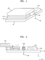
- FIG. 1 is a perspective view illustrating a triboelectric generator according to some example embodiments.
- FIG. 2 is a cross-sectional view illustrating the triboelectric generator shown in FIG. 1 .
- the triboelectric generator may include a first electrode 122 and a second electrode 124 spaced apart from each other, a first charging part 110 disposed on a surface S1 of the first electrode 122, a second charging part 140 slidable in a direction (x-axis direction) on a surface S2 of the first charging part 110 and a surface S3 of the second electrode 124, and a grounding unit 130 configured to intermittently connect the second charging part 140 to a charge reservoir 133 according to the movement of the second charging part 140.
- the triboelectric generator may include a sliding mechanism to induce a horizontal motion of the second charging part 140 relative to the first charging part 110 or the second electrode 124 by an externally applied force and thus to bring adjacent surfaces into contact with each other.
- the second charging part 140 may rub on an upper surface of the first charging part 110 through a sliding motion.
- the expression “the second charging part 140 slides” refers to that the second charging part 140 moves relative to the first charging part 110, the grounding unit 130, and the second electrode 124. Therefore, sliding of the second charging part 140 may occur as the second charging part 140 moves.
- sliding of the second charging part 140 may occur as the first charging part 110, the grounding unit 130, and the second electrode 124 move relative to the second charging part 140.
- the expression “the second charging part 140 slides in a direction” refers to that the second charging part 140 slides in a direction in which the first charging part 110, the grounding unit 130, and the second electrode 124 are arranged. Therefore, the movement of the second charging part 140 is not limited to straight movement.
- the first charging part 110 may include a first material.
- the second charging part 140 may include a second material that is a different material than the first material.
- the second charging part 140 and the first charging part 110 may include materials having different charging ratings. Therefore, if a surface of the second charging part 140 is rubbed against the surface S2 of the first charging part 110, the surface S2 of the first charging part 110 and the surface of the second charging part 140 may be charged with different polarities.
- the types of charges of the first charging part 110 and the second charging part 140 are dependent on materials of the first charging part 110 and the second charging part 140, for example, may be determined by relative positions of the materials of the first charging part 110 and the second charging part 140 in a triboelectric series.
- the surface S2 of the first charging part 110 may be charged with a negative charge by friction with the second charging part 140, and the surface of the second charging part 140 may be charged with a positive charge by friction with the first charging part 110.
- the second charging part 140 may include a conductive material for easy electric connection with the grounding unit 130.
- the conductive material may include a metallic material that is easily charged by friction, such as aluminum (Al), copper (Cu), gold (Au), or steel.
- the first charging part 110 may include at least one of polytetrafluoroethylene (Teflon), fluorinated ethylene propylene (FEP), poly(methyl methacrylate) (PMMA), polyvinylidene fluoride (PVDF), polycarbonate (PC), polyvinyl chloride (PVC), polyimide (Kapton), polypropylene (PP), polyethylene (PE), and polystyrene (PS) that are easily charged with a negative charge by friction with the conductive material of the second charging part 140.
- Teflon polytetrafluoroethylene
- FEP fluorinated ethylene propylene
- PMMA poly(methyl methacrylate)
- PVDF polyvinylidene fluoride
- PC polycarbonate
- PVC polyvinyl chloride
- PVC polyimide
- PP polypropylene
- PE polyethylene
- PS polystyrene
- the first charging part 110 may include an organic polymer such as poly(methyl methacrylate) PMMA, polyethylene terephthalate (PET), polyetheretherketone (PEEK), cycloolefin copolymer (COC), or polytetrafluoroethylene (PTFE).
- the first charging part 110 may include an inorganic polymer such as polydimethylsiloxane (PDMS) or organically modified ceramic (ORMOCER).
- PDMS polydimethylsiloxane
- ORMOCER organically modified ceramic
- the surface S2 of the first charging part 110 may be charged with a positive charge by friction with the second charging part 140, and the surface of the second charging part 140 may be charged with a negative charge by friction with the first charging part 110.
- the second charging part 140 may include a conductive material for easy electric connection with the grounding unit 130.
- the conductive material may include at least one of aluminum (Al), copper (Cu), gold and steel that are easily charged by friction.
- the first charging part 110 may include at least one of polyformaldehyde, ethylcellulose, polyamide, melamine formol, wool, silk, mica, and nylon that are easily charged with a positive charge by friction with the conductive material.
- the above-listed materials are examples, and inventive concepts are not limited thereto.
- At least one of the first and second charging parts 110 and 140 may be doped with a p-type dopant or an n-type dopant so as to adjust charging characteristics of the surface thereof.
- a source of the p-type dopant may include ionic liquids such as NO 2 BF 4 , NOBF 4 , or NO 2 SbF 6 ; acidic compounds such as HCl, H 2 PO 4 , CH 3 COOH, H 2 SO 4 , or HNO 3 ; and organic compounds such as dichlorodicyanoquinone (DDQ), oxone, dimyristoylphosphatidylinositol (DMPI), or trifluoromethanesulfoneimide.
- DDQ dichlorodicyanoquinone
- DMPI dimyristoylphosphatidylinositol
- source of the p-type dopant may include HPtCl 4 , AuCl 3 , HAuCl 4 , AgOTf (silver trifluoromethanesulfonate), AgNO 3 , H 2 PdCl 6 , Pd(OAc) 2 , and Cu(CN) 2 .
- Examples of a source of the n-type dopant may include a reduction product of a substituted or unsubstituted nicotinamide; a reduction product of a compound which is chemically bound to a substituted or unsubstituted nicotinamide; and a compound including at least two pyridinium moieties in which a nitrogen atom of at least one of the pyridinium moieties is reduced.
- the source of the n-type dopant may include nicotinamide mononucleotide-H (NMNH), nicotinamide adenine dinucleotide-H (NADH), nicotinamide adenine dinucleotide phosphate-H (NADPH), or viologen.
- the source of the n-type dopant may include a polymer such as polyethyleneimine (PEI).
- the n-type dopant may include an alkali metal such as potassium (K) or lithium (Li).
- K potassium
- Li lithium
- the grounding unit 130 may be electrically connected to the charge reservoir 133.
- the charge reservoir 133 may include ground or a conductive member having substantially no variation in electric potential.
- the charge reservoir 133 and the second charging part 140 may be electrically connected to each other through the grounding unit 130. If the second charging part 140 is connected to the charge reservoir 133 through the grounding unit 130, the electric potential of the second charging part 140 may become substantially equal to the electric potential of the charge reservoir 133.
- the first and second electrodes 122 and 124 may be spaced apart from each other in a direction in which the second charging part 140 slides.
- the first and second electrodes 122 and 124 may include a material having a high degree of electric conductivity.
- the first and second electrodes 122 and 124 may include at least one of graphene, carbon nanotube (CNT), indium tin oxide (ITO), a metal, and a conductive polymer.
- the metal may include at least one of silver (Ag), aluminum (Al), copper (Cu), gold (Au), nickel (Ni), chromium (Cr), and platinum (Pt).
- the metal is not limited thereto.
- the first and second electrodes 122 and 124 may have a single-layer or multilayer structure.
- Electrostatic induction may occur between the first and second electrodes 122 and 124 as the second charging part 140 slides. That is, while the second charging part 140 slides, charge may flow between the first and second electrodes 122 and 124 by electrostatic induction.
- the triboelectric generator may harvest energy from flow of charge between the first and second electrodes 122 and 124.
- FIG. 3 illustrates a modification of the triboelectric generator illustrated in FIGS. 1 and 2 , according to some example embodiments.
- FIG. 3 illustrates a modification of the triboelectric generator illustrated in FIGS. 1 and 2 , according to some example embodiments.
- the same descriptions as those given above with reference to FIGS. 1 and 2 will not be repeated.
- a plurality of protrusions may be formed on at least one of contact surfaces between the first charging part 110 and the second charging part 140.
- the protrusions may include nano-pyramids, nano-wires, nano-balls, nano-rods, or the like. Since the protrusions are formed on at least one of the contact surfaces between the first charging part 110 and the second charging part 140, when the first charging part 110 and the second charging part 140 are brought into contact with each other, the amount of charge induced on each of the contact surface of the first charging part 110 and the contact surface of the second charging part 140 may be increased.
- FIG. 4 illustrates a modification of the triboelectric generator illustrated in FIGS. 1 and 2 , according to some example embodiments.
- a charge reservoir may include a conductive member 131.
- the conductive member 133a has a plate shape.
- the charge reservoir may be a conductive member having a high degree of capacity. If the charge reservoir is connected to the second charging part 140 through the grounding unit 130, the charge reservoir may exchange charges with the second charging part 140. That is, the charge reservoir may vary the electric potential of the second charging part 140 by exchanging charges with the second charging part 140. For example, the electric potential of the charge reservoir may be substantially the same as the electric potential of ground.
- FIG. 5 is a view illustrating a state in which the second charging part 140 is moved relative to the first charging part 110 through a sliding motion.
- charges illustrated in the drawings are examples. That is, there may be various flows of charge in triboelectric generators of various embodiments.
- the first and second charging parts 110 and 140 are moved relative to each other. That is, sliding of the second charging part 140 may occur by the movement of the second charging part 140, the first charging part 110, or both the first and second charging parts 110 and 140.
- the first and second electrodes 122 and 124 and the grounding unit 130 may be arranged on a first substrate 10.
- the grounding unit 130 may be disposed between the first and second electrodes 122 and 124. While the second charging part 140 moves relative to the first substrate 10, the second charging part 140 may sequentially make contact with surfaces of the first charging part 110, the grounding unit 130, and the second electrode 124.
- the first and second charging parts 110 and 140 may be charged with opposite polarities.
- electrons move from the surface of the second charging part 140 to the surface of the first charging part 110 because of friction between the second charging part 140 and the first charging part 110.
- the second charging part 140 may be charged with a positive charge
- the first charging part 110 may be charged with a negative charge.
- this is merely an example. That is, the opposite case may also be possible.
- electrons may move from the surface of the first charging part 110 to the surface of the second charging part 140, and thus the first charging part 110 may be charged with a positive charge and the second charging part 140 may be charged with a negative charge.
- FIG. 6 is a view illustrating a state in which the second charging part 140 meets the grounding unit 130 as a result of a sliding motion.
- the second charging part 140 may be brought into contact with an upper surface of the grounding unit 130 through a sliding motion. Since a portion of the upper surface of the first charging part 110 is not in contact with the second charging part 140, electrostatic induction may occur between the first and second electrodes 122 and 124. Electrons may move from the first electrode 122 to the second electrode 124 because of the electrostatic induction. While current flows between the first and second electrodes 122 and 124, electric energy may be harvested using a load 30 between the first and second electrodes 122 and 124.
- the distance d1 between the first charging part 110 and the grounding unit 130 may be less than the width W of the second charging part 140.
- the width W of the second charging part 140 refers to a length of the second charging part 140 in the sliding direction of the second charging part 140. Since the width W of the second charging part 140 is greater than the distance d1 between the first electrode 122 and the grounding unit 130, the second charging part 140 may contact both the first charging part 110 and the grounding unit 130 at the same time. Therefore, while current flows between the first and second electrodes 122 and 124 by electrostatic induction, electrons may be supplied to the second charging part 140 through the grounding unit 130, and thus the electric potential of the second charging part 140 may vary.
- the distance d1 between the first charging part 110 and the grounding unit 130 may be greater than the width W of the second charging part 140.
- the second charging part 140 may make contact with the grounding unit 130 after separating from the first charging part 110.
- the second charging part 140 may be electrically connected to the charge reservoir 133.
- the second charging part 140 may include a conductive material for easy electric connection. If the second charging part 140 is brought into contact with the grounding unit 130, the second charging part 140 and the charge reservoir 133 may exchange charges with each other. Owing to this exchange of charges, the electric potential of the second charging part 140 may become equal to the electric potential of the charge reservoir 133. For example, if the electric potential of the charge reservoir 133 is equal to the electric potential of the ground, the charge reservoir 133 may supply electrons to the second charging part 140 through the grounding unit 130.
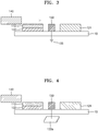
- FIG. 7 is a view illustrating a state in which the second charging part 140 is further moved relative to the first substrate 10 through a sliding motion.
- the contact area between the second charging part 140 and the first charging part 110 may gradually decrease because of sliding. As the contact area between the second charging part 140 and the first charging part 110 decreases, electrostatic induction may occur between the first and second electrodes 122 and 124. Due to the electrostatic induction, current may flow between the first and second electrodes 122 and 124. The electric potential of the second charging part 140 may be maintained to be close to the electric potential of the ground.
- FIG. 8 is a view illustrating a state in which the second charging part 140 meets the second electrode 124 as a result of a sliding motion.
- the first and second charging parts 110 and 140 may separate from each other.
- the second charging part 140 may make contact with the grounding unit 130 and the second electrode 124.
- the distance d2 between the grounding unit 130 and the second electrode 124 may be less than the width W of the second charging part 140.
- the electric potential of the second electrode 124 may vary because of the charge reservoir 133.
- the electric potential of the second electrode 124 may become substantially equal to the electric potential of the ground.
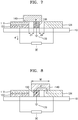
- FIG. 9 is a view illustrating a state in which the second charging part 140 is further moved relative to the first substrate 10 as a result of sliding.
- the electric potential of the second charging part 140 and the second electrode 124 may become substantially equal to the electric potential of the ground.
- FIG. 10 is a view illustrating a state in which the second charging part 140 is separate from the second electrode 124 as a result of a sliding motion.
- a first cycle illustrated with reference to FIGS. 5 to 10 may terminate.
- the first charging part 110 may be maintained in a negatively charged state.
- the first electrode 122 may have a relatively large amount of positive charge compared to the amount of negative charge because of the influence of negative charge of the first charging part 110.
- charge equilibrium is established as illustrated in FIG. 10 , there may be substantially no movement of charge until the next cycle in which the second charging part 140 and the first charging part 110 meet each other.
- the next cycle starts after the second charging part 140 and the second electrode 124 have the electric potential of the ground, a larger amount of electric energy may be obtained in the next cycle.
- FIG. 11 is a view illustrating a state in which the second charging part 140 approaches the first charging part 110.
- the first charging part 110 may already have a negative charge unlike the case described with reference to FIG. 5 .
- FIG. 12 is a view illustrating a state in which the second charging part 140 contacts the first charging part 110 through a sliding motion.
- the amount of electron exchange between the first and second charging parts 110 and 140 may be relatively small.
- the second charging part 140 may be affected by the negative charge distributed on the surface of the first charging part 110.
- a positive charge may be induced on a lower surface of the second charging part 140, and a negative charge may be induced on an upper surface of the second charging part 140.
- FIG. 13 is a view illustrating a state in which the second charging part 140 meets the grounding unit 130 as a result of a sliding motion.
- the electric potential of the second charging part 140 may vary to the electric potential of the ground. In this process, electrons may move from the second charging part 140 to the grounding unit 130.
- FIG. 14 is a view illustrating a state in which the electric potential of the second charging part 140 is varied by the flow of electrons illustrated in FIG. 13 .
- a positive charge may remain in a portion of the second charging part 140 making contact with the first charging part 110.
- the remaining positive charge of the second charging part 140 may be balanced with the negative charge on the surface of the first charging part 110, and thus the electric potential of the second charging part 140 may become equal to the electric potential of the ground.
- the amount of positive charge may be greater than the amount of negative charge in the second charging part 140.
- electrostatic induction may occur between the first and second electrodes 122 and 124. Due to the electrostatic induction, electrons may move from the second electrode 124 to the first electrode 122 for electrical equilibrium. As electrons flow between the first and second electrodes 122 and 124, electric energy may be harvested using the load 30 between the first and second electrodes 122 and 124.
- FIG. 15 is a view illustrating a state in which the second charging part 140 is further moved relative to the first substrate 10 as a result of a sliding motion.
- the contact area between the second charging part 140 and the first charging part 110 decreases, electrons may move from the first electrode 122 to the second electrode 124. In addition, electrons may move from the charge reservoir 133 to the second charging part 140, maintaining the electric potential of the second charging part 140 to be equal to the electric potential of the ground. Since the second charging part 140 receives an external charge through the grounding unit 130, the amount of energy harvest through the load 30 may be amplified during sliding of the second charging part 140.
- FIG. 16 is a view illustrating a state in which the second charging part 140 is in contact with the second electrode 124 as a result of a sliding motion.
- the first and second charging parts 110 and 140 may separate from each other.
- the second charging part 140 may make contact with the grounding unit 130 and the second electrode 124.
- the distance d2 between the grounding unit 130 and the second electrode 124 may be less than the width W of the second charging part 140.
- the second electrode 124 may be connected to the charge reservoir 133 through the second charging part 140 and the grounding unit 130. As electrons move from the charge reservoir 133 to the second electrode 124, the electric potential of the second electrode 124 may become equal to the electric potential of the charge reservoir 133. For example, the electric potential of the second electrode 124 may become substantially equal to the electric potential of the ground.
- FIG. 17 is a view illustrating a state in which the second charging part 140 is separate from the second electrode 124 as a result of a sliding motion in the state shown in FIG. 16 .
- the cycle illustrated with reference to FIGS. 11 to 16 may terminate.
- the first and second charging parts 110 and 140 and the first and second electrodes 122 and 124 may have the same charge distribution as that shown in FIG. 11 . Therefore, if the second charging part 140 is slid again on the upper surface of the first charging part 110, the processes described with reference to FIGS. 11 to 16 may be repeated. Thus, while the cycle is repeated, electric energy may be harvested from current flowing between the first and second electrodes 122 and 124.
- the grounding unit 130 may exchange charges with the second charging part 140 and the second electrode 124. Since the second charging part 140 and the second electrode 124 exchange charges with the charge reservoir 133, which is an external device, the amount of electric energy harvest may be increased during sliding cycles.
- the first and second electrodes 122 and 124, the first charging part 110, and the grounding unit 130 are disposed on the first substrate 10 having a flat shape.
- inventive concepts are not limited thereto.
- the first substrate 10 may have any other shape to easily repeat the cycles illustrated with reference to FIGS. 1 to 17 .
- FIG. 18 is a perspective view illustrating a triboelectric generator having a different shape, according to some example embodiments.
- the triboelectric generator may include a first substrate 10 having a circular plate shape.
- a first electrode 122, a grounding unit 130, and a second electrode 124 may be arranged on the first substrate 10 in radial directions.
- a first charging part 110 may be placed on an upper surface of the first electrode 122.
- the first electrode 122, the first charging part 110, the grounding unit 130, and the second electrode 124 may have a fan shape.
- inventive concepts are not limited thereto.
- a second charging part 140 may face an upper surface of the first substrate 10 and may be rotatable relative to the first substrate 10.
- the triboelectric generator may further include a second substrate 12 on which the second charging part 140 is disposed.
- the second substrate 12 may have a circular plate shape.
- the second charging part 140 may slide on upper surfaces of the first charging part 110, the grounding unit 130, and the second electrode 124.
- inventive concepts are not limited thereto.
- the triboelectric generator may not include the second substrate 12.
- a rotation center of the second charging part 140 may be connected to the first substrate 10 so that the second charging part 140 may be slid on the upper surfaces of the first charging part 110, the grounding unit 130, and the second electrode 124.
- the first electrode 122, the grounding unit 130, and the second electrode 124 are arranged on the first substrate 10.
- inventive concepts are not limited thereto.
- a plurality of sets each including a first electrode 122, a grounding unit 130, and a second electrode 124 may be disposed on the first substrate 10.
- a plurality of second charging parts 140 may be disposed on the second substrate 12.
- FIG. 19 is a perspective view illustrating a triboelectric generator having a different shape, according to some example embodiments.
- the triboelectric generator may include a first substrate 10 and a second substrate 12 that have a circular plate shape.
- a first electrode 122 and a second electrode 124 may be arranged on the first substrate 10 in radial directions.
- a first charging part 110 may be placed on an upper surface of the first electrode 122.
- a grounding unit 130 may be placed on the second substrate 12.
- a rotation center of a second charging part 140 may be connected to the first and second substrates 10 and 12.
- the second charging part 140 may move between the first and second substrates 10 and 12. While the second charging part 140 moves relative to the first and second substrates 10 and 12, the second charging part 140 may sequentially slide on surfaces of the first charging part 110, the grounding unit 130, and the second electrode 124.
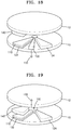
- FIG. 20 is a perspective view illustrating a triboelectric generator having a different shape, according to some example embodiments.
- the triboelectric generator may include a first substrate 10 having a circular plate shape.
- a first electrode 122 and a second electrode 124 may be arranged on the first substrate 10 in radial directions.
- a first charging part 110 may be placed on an upper surface of the first electrode 122.
- the triboelectric generator may include a ring having a conductive material portion 132 and an insulative (e.g. insulating) material portion 134.
- the conductive material portion 132 may be electrically connected to a charge reservoir 133 so as to function as a grounding unit.
- a second charging part 140 may slide on an inner circumferential surface of the ring through a rotation motion relative to the ring. While the second charging part 140 slides on an inner circumferential surface of the insulative material portion 134, the charge reservoir 133 and the second charging part 140 may not be electrically connected to each other. While the second charging part 140 slides on an inner circumferential surface of the conductive material portion 132, the charge reservoir 133 and the second charging part 140 may be electrically connected to each other.
- the conductive material portion 132 may be located between the first charging part 110 and the second charging part 140.
- FIG. 21 is a perspective view illustrating a triboelectric generator having a different shape, according to some example embodiments.
- the triboelectric generator may include a first substrate 10 having a circular plate shape.
- a first electrode 122 and a second electrode 124 may be arranged on the first substrate 10 in radial directions.
- a first charging part 110 may be placed on an upper surface of the first electrode 122.
- the triboelectric generator may include a cylindrical case 40 having a conductive material portion 132 and an insulative material portion134.
- the conductive material portion 132 may be electrically connected to a charge reservoir 133 so as to function as a grounding unit.
- a second charging part 140 may slide on an inner wall of the case 40 through a rotation motion relative to the case 40. While the second charging part 140 slides on an inner wall of the insulative material portion 134, the charge reservoir 133 and the second charging part 140 may not be electrically connected to each other. While the second charging part 140 slides on an inner wall of the conductive material portion 132, the charge reservoir 133 and the second charging part 140 may be electrically connected to each other.
- the conductive material portion 132 may be located between the first charging part 110 and the second charging part 140.
- FIG. 22 is a cross-sectional view illustrating a triboelectric generator having a different shape, according to some example embodiments.
- the triboelectric generator may include a third substrate 16 on which a first electrode 122, a grounding unit 130, and a second electrode 124 are arranged.
- the third substrate 16 may have a circular post shape.
- inventive concepts are not limited thereto.
- the third substrate 16 may have a hollow cylindrical shape.
- the first electrode 122, the grounding unit 130, and the second electrode 124 may be disposed on an outer surface S4 of the third substrate 16.
- the grounding unit 130 may be connected to a charge reservoir 133.
- a first charging part 110 may be disposed on an upper surface of the first electrode 122.
- a second charging part 140 may move while facing the outer surface S4 of the first substrate 10.
- the triboelectric generator may further include a fourth substrate 18 on which the second charging part 140 is disposed.
- the second charging part 140 may be disposed on an inner surface S5 of the fourth substrate 18.
- the second charging part 140 may sequentially slide on upper surfaces of the first charging part 110, the grounding unit 130, and the second electrode 124. In this manner, the cycles described with reference to FIGS. 5 to 17 may be repeated.
- the first electrode 122, the grounding unit 130, and the second electrode 124 are arranged on the third substrate 16.
- inventive concepts are not limited thereto.
- a plurality of sets each including a first electrode 122, a grounding unit 130, and a second electrode 124 may be disposed on the outer surface S4 of the third substrate 16.
- a plurality of second charging parts 140 may be disposed on the inner surface S5 of the second substrate 12.
- the second charging parts 140 may be disposed on the outer surface S4 of the third substrate 16, and the first electrode 122, the first charging part 110, the grounding unit 130, and the second electrode 124 may be disposed on the inner surface S5 of the fourth substrate 18.
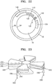
- FIG. 23 illustrates a triboelectric generator having a different shape, according to some example embodiments.
- a second charging part 240 may be slid on a first charging part 210 while being rotated relative to the first charging part 210.
- the second charging part 240 may slide on surfaces of the first charging part 210 and a second electrode 224 at a position between the first charging part 210 and the second electrode 224.
- a first electrode 222 and the second electrode 224 may be spaced apart from each other in a direction in which the second charging part 240 slides.
- the first charging part 210 may be disposed on a lower surface of the first electrode 222 facing the second charging part 240.
- the second charging part 240 may face the first charging part 210 and may intermittently contact the first charging part 210 through a sliding motion.
- the second charging part 240 may intermittently contact the second electrode 224 through a sliding motion.
- a grounding unit 230 may include a conductive post.
- the grounding unit 230 may be electrically connected to a charge reservoir 233, and when the second charging part 240 rotates, the grounding unit 230 may intermittently contact the second charging part 240.
- the second charging part 240 may include protrusions 242 on outer surfaces thereof. When the second charging part 240 rotates, the protrusions 242 may intermittently contact the grounding unit 230.
- Each of the first and second charging parts 210 and 240 and the first and second electrodes 222 and 224 may include a plurality of radially extending wings.
- the first and second charging parts 210 and 240 and the first and second electrodes 222 and 224 may have a fan shape.
- FIG. 24 is a schematic cross-sectional view illustrating the triboelectric generator according to some example embodiments.
- the second charging part 240 may be separate from the grounding unit 230, the second electrode 224, and the first charging part 210.
- the first charging part 210 may move in interlock with the first electrode 222.
- the first charging part 210 may approach the second charging part 240 as a result of a relative movement.
- FIG. 25 is a view illustrating a state in which the first and second charging parts 210 and 240 are in contact with each other.
- the first and second charging parts 210 and 240 may contact each other through a sliding motion.
- surfaces of the first and second charging parts 210 and 240 may be charged with different polarities.
- the first and second charging parts 210 and 240 may move in interlock with each other.
- the first and second charging parts 210 and 240 may move in interlock with each other like the hour and minute hands of a clock.
- FIG. 26 is a view illustrating a state in which the second charging part 240 is in contact with the grounding unit 230.
- a protrusion 242 of the second charging part 240 may contact the grounding unit 230.
- the electric potentials of the second charging part 240 and the charge reservoir 233 may become equal to each other.
- the electric potential of the second charging part 240 may become substantially equal to the electric potential of ground.
- FIG. 27 is a view illustrating a state in which the second charging part 240 is in contact with the second electrode 224.
- the second charging part 240 may contact the second electrode 224 through a sliding motion.
- the electric potential of the second electrode 224 may also become equal to the electric potential of the ground.
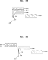
- FIGS. 28 and 29 are views illustrating the second charging part 240 separating from the second electrode 224 and the first charging part 210.
- the second charging part 240 first separates from the second electrode 224.
- inventive concepts are not limited thereto.
- the second charging part 240 may first separate from the first charging part 210 and may then separate from the second electrode 224.
- the second charging part 240 may separate from the first charging part 210 and the second electrode 224 substantially at the same time. Thereafter, as shown in FIG. 29 , the second charging part 240 may separate from the grounding unit 230.
- the electric potential of the second electrode 224 may not be equal to the electric potential of the ground.
- the first and second electrodes 222 and 224 may have different electric potentials. If the first and second electrodes 222 and 224 have different electric potentials, current may flow between the first and second electrodes 222 and 224. While current flows between the first and second electrodes 222 and 224, electric energy may be harvested using a load 30 between the first and second electrodes 222 and 224.
- the second charging part 240 and the second electrode 224 may exchange charges with the outside through the grounding unit 230, and thus the amount of current flowing between the first and second electrodes 222 and 224 may be further amplified.
- the first charging part 210, the second charging part 240, the second electrode 224, and the grounding unit 230 are all separate from each other. From this state, the processes described with reference to FIGS. 24 to 29 may be repeated.
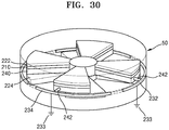
- FIG. 30 is a view illustrating a modification of the triboelectric generator shown in FIG. 23 .
- a grounding unit may include conductive members 232 and insulative members 234 alternately arranged in a direction in which a second charging part 240 rotates.
- the conductive members 232 may be electrically connected to a charge reservoir 233, and when the second charging part 240 rotates, the conductive members 232 may intermittently contact the second charging part 240 for example, the conductive members 232 and the insulative members 234 may be disposed on an inner wall of a cylindrical case 50.
- the distribution of the conductive members 232 may be determined such that the conductive members 232 may contact the second charging part 240 in the same regions as the regions in which the second charging part 240 and the grounding unit 230 illustrated in FIGS. 26 to 28 contact each other.
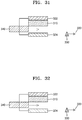
- FIG. 31 is a cross-sectional view illustrating a triboelectric generator according to some example embodiments.
- the triboelectric generator may include: a first electrode 322 and a second electrode 324 spaced apart from each other; a first charging part 310 disposed on a lower surface of the first electrode 322; a second charging part 340 configured to slide in a direction (x-axis direction) while facing a lower surface of the first charging part 310, so as to be charged with a polarity opposite to that of the first charging part 310 as a result of contact with the first charging part 310; and a grounding unit 330 configured to intermittently connect the second charging part 340 to a charge reservoir 333 according to the movement of the second charging part 340.
- the second charging part 340 may move relative to the first charging part 310 and the second electrode 324 at a position between the first charging part 310 and the second electrode 324.
- the second charging part 340 may contact the lower surface of the first charging part 310 through a sliding motion.
- the second charging part 340 may be spaced apart from the second electrode 324. Therefore, while the second charging part 340 slides on the lower surface of the first charging part 310, the second charging part 340 may not contact the second electrode 324.
- the second charging part 340 and the first charging part 310 may include materials having different charging ratings. Therefore, when surfaces of the second charging part 340 and the first charging part 310 rub together, the first charging part 310 and the second charging part 340 may be charged with different polarities.
- the first charging part 310 may be charged with a negative charge by friction with the second charging part 340, and the second charging part 340 may be charged with a positive charge by friction with the first charging part 310.
- the second charging part 340 may include a conductive material for easy electric connection with the grounding unit 330.
- the conductive material may include at least one of aluminum (Al), copper (Cu), gold (Au), and steel that are easily charged by friction.
- the first charging part 310 may include at least one of polytetrafluoroethylene (Teflon), fluorinated ethylene propylene (FEP), poly(methyl methacrylate) (PMMA), polyvinylidene fluoride (PVDF), polycarbonate (PC), polyvinyl chloride (PVC), polyimide (Kapton), polypropylene (PP), polyethylene (PE), and polystyrene (PS) that are easily charged with a negative charge by friction with the conductive material of the second charging part 340.
- Teflon polytetrafluoroethylene
- FEP fluorinated ethylene propylene
- PMMA poly(methyl methacrylate)
- PVDF polyvinylidene fluoride
- PC polycarbonate
- PVC polyvinyl chloride
- PVC polyimide
- PP polypropylene
- PE polyethylene
- PS polystyrene
- the first charging part 310 may include an organic polymer such as poly(methyl methacrylate) PMMA, polyethylene terephthalate (PET), polyetheretherketone (PEEK), cycloolefin copolymer (COC), or polytetrafluoroethylene (PTFE).
- the first charging part 310 may include an inorganic polymer such as polydimethylsiloxane (PDMS) or organically modified ceramic (ORMOCER).
- PDMS polydimethylsiloxane
- ORMOCER organically modified ceramic
- the first charging part 310 may be charged with a positive charge by friction with the second charging part 340, and the second charging part 340 may be charged with a negative charge by friction with the first charging part
- the second charging part 340 may include a conductive material for easy electric connection with the grounding unit 330.
- the conductive material may include at least one of aluminum (Al), copper (Cu), gold (Au), and steel that are easily charged by friction.
- the first charging part 310 may include at least one of polyformaldehyde, ethylcellulose, polyamide, melamine formol, wool, silk, mica, and nylon that are easily charged with a positive charge by friction with the conductive material.
- the above-listed materials are examples, and inventive concepts are not limited thereto.
- At least one of the first and second charging parts 310 and 340 may be doped with a p-type dopant or an n-type dopant so as to adjust charging characteristics of the surface thereof.
- a source of the p-type dopant may include ionic liquids such as NO 2 BF 4 , NOBF 4 , or NO 2 SbF 6 ; acidic compounds such as HCl, H 2 PO 4 , CH 3 COOH, H 2 SO 4 , or HNO 3 ; and organic compounds such as dichlorodicyanoquinone (DDQ), oxone, dimyristoylphosphatidylinositol (DMPI), or trifluoromethanesulfoneimide.
- DDQ dichlorodicyanoquinone
- DMPI dimyristoylphosphatidylinositol
- source of the p-type dopant may include HPtCl 4 , AuCl 3 , HAuCl 4 , AgOTf (silver trifluoromethanesulfonate), AgNO 3 , H 2 PdCl 6 , Pd(OAc) 2 , and Cu(CN) 2 .
- Examples of a source of the n-type dopant may include a reduction product of a substituted or unsubstituted nicotinamide; a reduction product of a compound which is chemically bound to a substituted or unsubstituted nicotinamide; and a compound including at least two pyridinium moieties in which a nitrogen atom of at least one of the pyridinium moieties is reduced.
- the source of the n-type dopant may include nicotinamide mononucleotide-H (NMNH), nicotinamide adenine dinucleotide-H (NADH), nicotinamide adenine dinucleotide phosphate-H (NADPH), or viologen.
- the source of the n-type dopant may include a polymer such as polyethyleneimine (PEI).
- the n-type dopant may include an alkali metal such as potassium (K) or lithium (Li).
- K potassium
- Li lithium
- the grounding unit 330 may be electrically connected to the charge reservoir 333.
- the charge reservoir 133 may include ground or a conductive member, the electric potential of which substantially does not vary, that is, maintains substantially a constant value.
- the charge reservoir 333 and the second charging part 340 may be electrically connected to each other through the grounding unit 330.
- the electric potential of the second charging part 340 may become substantially equal to the electric potential of the charge reservoir 333.
- the first and second electrodes 322 and 324 may include a material having a high degree of electric conductivity.
- the first and second electrodes 322 and 324 may include at least one of graphene, carbon nanotube (CNT), indium tin oxide (ITO), a metal, and a conductive polymer.
- the metal may include at least one of silver (Ag), aluminum (Al), copper (Cu), gold (Au), nickel (Ni), chromium (Cr), and platinum (Pt).
- the metal is not limited thereto.
- the first and second electrodes 322 and 324 may have a single-layer or multilayer structure.
- FIG. 32 is a view illustrating a modification of the triboelectric generator shown in FIG. 31 .
- the same description as that given above with reference to FIG. 31 will not be repeated.
- a plurality of protrusions may be formed on at least one of contact surfaces between the first charging part 310 and the second charging part 340.
- the protrusions may include nano-pyramids, nano-wires, nano-balls, nano-rods, or the like. Since the protrusions are formed on at least one of the contact surfaces between the first charging part 310 and the second charging part 340, when the first charging part 310 and the second charging part 340 are brought into contact with each other, the amount of charge induced on each of the contact surface of the first charging part 310 and the contact surface of the second charging part 340 may be increased.
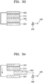
- FIG. 33 is a view illustrating a state in which the first and second charging parts 310 and 340 shown in FIG. 31 are in contact with each other as a result of a sliding motion.
- the surfaces of the first and second charging parts 310 and 340 may be charged with different polarities.
- the surface of the second charging part 340 is charged with a positive charge
- the surface of the first charging part 310 is charged with a negative charge.
- inventive concepts are not limited thereto.
- the surface of the first charging part 310 may be charged with a positive charge
- the surface of the second charging part 340 may be charged with a negative charge.
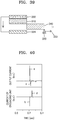
- FIG. 34 illustrates a state in which the second charging part 340 is moved relative to the first charging part 310 through a sliding motion.
- Electrons may move from the first electrode 322 to the second electrode 324 because of electrostatic induction occurring in a region close to the portion of the surface of the first charging part 310 that is not in contact with the second charging part 340. That is, current may flow between the first and second electrodes 322 and 324.
- FIG. 35 is a view illustrating a state in which the second charging part 340 is in contact with the grounding unit 330 as a result of a sliding motion.
- the second charging part 340 may contact the grounding unit 330 and may exchange charges with the charge reservoir 333. Since the second charging part 340 exchanges charges with the charge reservoir 333, the electric potential of the second charging part 340 may become equal to the electric potential of the charge reservoir 333. For example, electrons may move from the charge reservoir 333 to the second charging part 340, and thus the electric potential of the second charging part 340 may become substantially equal to the electric potential of the ground.
- FIG. 36 is a view illustrating a state in which the second charging part 340 approaches again the first charging part 310 after the cycle described with reference to FIGS. 31 to 34 is completed.
- the surface of the first charging part 310 may have a negative charge.
- the first electrode 322 may have a relatively large amount of positive charge
- the second electrode 324 may have a relatively large amount of negative charge.
- FIG. 37 is a view illustrating a state in which the second charging part 340 is in contact with the first charging part 310 as a result of a sliding motion.
- the amount of electron exchange between the first and second charging parts 310 and 340 may be relatively small.
- the second charging part 340 may be affected by the negative charge on the surface of the first charging part 310.
- a positive charge may be induced on an upper surface of the second charging part 340, and a negative charge may be induced on a lower surface of the second charging part 340.
- FIG. 38 is a view illustrating a state in which the second charging part 340 is moved relative to the first charging part 310 through a sliding motion.
- Electrons may move from the first electrode 322 to the second electrode 324 because of electrostatic induction occurring in a region close to the portion of the surface of the first charging part 310 that is not in contact with the second charging part 340.
- current flowing between the first and second electrodes 322 and 324 may be increased. That is, the amount of current flowing between the first and second electrodes 322 and 324 may be larger in the case of using the grounding unit 330 than in the case of not using the grounding unit 330.
- FIG. 39 is a view illustrating a state in which the second charging part 340 is in contact with the grounding unit 330 as a result of a sliding motion.
- the second charging part 340 may contact the grounding unit 330 and may exchange charges with the charge reservoir 333. Since the second charging part 340 exchanges charges with the charge reservoir 333, the electric potential of the second charging part 340 may become equal to the electric potential of the charge reservoir 333. For example, electrons may move from the charge reservoir 333 to the second charging part 340, and thus the electric potential of the second charging part 340 may become substantially equal to the electric potential of the ground. As the electric potential of the second charging part 340 is equal to the electric potential of the ground, the first charging part 310 and the first and second electrodes 322 and 324 may have the same state as that shown in FIG. 35 . In addition, as the cycle described with reference to FIGS. 36 to 39 is repeated, electric energy may be repeatedly harvested. In addition, since the second charging part 340 exchanges charges with the charge reservoir 333, the amount of electric energy harvest may be increased during sliding cycles.
- FIG. 40 is a current-time graph of the triboelectric generator illustrated in FIGS. 1 to 17 , illustrating current flowing between the first and second electrodes 122 and 124, and current flowing in the grounding unit 130.
- the right curve indicates current flowing between the first and second electrodes 122 and 124
- the left curve indicates current flowing in the grounding unit 130.
- the curve indicating current flowing between the first and second electrodes 122 and 124 may include two peaks (a) and (c) in different directions. The reason for this is that the direction of electron movement between the first and second electrodes 122 and 124 shown in FIG. 14 is different from the direction of electron movement between the first and second electrodes 122 and 124 shown in FIG. 15 .
- the curve indicating current flowing in the grounding unit 130 may also have two peaks (b) and (d) in different directions. The reason for this is that the direction of electron movement in the grounding unit 130 shown in FIG. 14 is different from the direction of electron movement in the grounding unit 130 shown in FIG. 15 . Therefore, the output current flowing between the first and second electrodes 122 and 124 of the triboelectric generator may be alternating current.
- FIG. 41 is a graph for comparing an output current measured between the first and second electrodes 122 and 124 of the triboelectric generator described with reference to FIGS. 1 to 17 with an output current measured between the first and second electrodes 122 and 124 of the triboelectric generator after the grounding unit 130 was removed from the triboelectric generator.
- the left curve indicates an output current with respect to time in the case of not using the grounding unit 130
- the right curve indicates an output current with respect to time in the case of using the grounding unit 130.
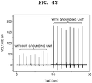
- FIG. 42 is a graph for comparing a voltage measured between the first and second electrodes 122 and 124 of the triboelectric generator described with reference to FIGS. 1 to 17 with a voltage measured between the first and second electrodes 122 and 124 of the triboelectric generator after the grounding unit 130 was removed from the triboelectric generator.
- the left curve indicates a voltage between the first and second electrodes 122 and 124 with respect to time in the case of not using the grounding unit 130
- the right curve indicates a voltage between the first and second electrodes 122 and 124 with respect to time in the case of using the grounding unit 130.
- current flowing between the first and second electrodes 122 and 124 may be lower than about 0.2 mA, and voltage between the first and second electrodes 122 and 124 may be merely about 50 V.
- grounding unit 130 when the grounding unit 130 is used, current and voltage between the first and second electrodes 122 and 124 may be amplified. Since the charge reservoir 133 and the second charging parts 140 exchange charges with each other through the grounding unit 130, current and voltage between the first and second electrodes 122 and 124 may be amplified.
- output current When the grounding unit 130 is used, output current may be increased by a factor of about 10, and a current peak of about 1 mA or greater may be obtained.
- output voltage when the grounding unit 130 is used, output voltage may be increased by a factor of about 4, and a voltage peak of about 150V to about 200 V may be obtained.
- FIG. 43 is a perspective view illustrating a triboelectric generator according to some example embodiments.
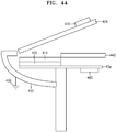
- FIG. 44 is a side view illustrating the triboelectric generator illustrated in FIG. 43
- FIG. 45 is a top view illustrating the triboelectric generator illustrated in FIG. 43 .
- the triboelectric generator may include: a first electrode 422 and a second electrode 424 spaced apart from each other; a first charging part 410 disposed on an upper surface of the first electrode 422; a second charging part 440 configured to be charged with a polarity opposite to that of the first charging part 410 when rubbed against the first charging part 410 through a sliding motion; and a first magnetic part 460.
- the triboelectric generator may include a second magnetic part 470 interlocked with the second electrode 424 so as to move the second electrode 424 relative to the second charging part 440 under the influence of magnetic force of the first magnetic part 460.
- the triboelectric generator may include a grounding unit 430 configured to intermittently connect a charge reservoir 433 to the second charging part 440 and the second electrode 424 to which the second magnetic part 470 is attached.
- the first charging part 410, the first electrode 422, the grounding unit 430, and the first magnetic part 460 may be interlocked with each other. Therefore, when the first charging part 410 rotates relative to the second charging part 440 and the second electrode 424, the first electrode 422, the grounding unit 430, and the first magnetic part 460 may also rotate relative to the second charging part 440 and the second electrode 424.
- Rotation of the second charging part 440 relative to the first charging part 410 may occur when the first charging part 410 or the second charging part 440 rotates. That is, rotation of the second charging part 440 relative to the first charging part 410 may be accomplished by rotating the second charging part 440, or rotating the first charging part 410 in a state in which the second charging part 440 is fixed. In addition, rotation of the second charging part 440 relative to the first charging part 410 may be accomplished by rotating both the first and second charging parts 410 and 440.
- the triboelectric generator may include a first substrate 10a on which the first electrode 422 and the first magnetic part 460 are disposed.
- a rotation shaft of the grounding unit 430 may be interlocked with the first substrate 10a.
- the first substrate 10a may have a circular plate shape for ease of rotation.
- the first electrode 422 and the first charging part 410 may have a fan shape.
- FIG. 43 the first electrode 422 and the first charging part 410 are illustrated as having a semicircular plate shape.
- inventive concepts are not limited thereto.
- the first electrode 422 and the first charging part 410 may have a fan shape, and the central angle of the fan shape may not be 180°.
- the first electrode 422 and the first charging part 410 may having a radially extending shape other a fan shape.
- the second charging part 440 may also have a fan shape or a radially extending shape.
- the first charging part 410 rotates together with the first substrate 10a.
- inventive concepts are not limited thereto.
- the second charging part 440 and the second magnetic part 470 may rotate relative to the first charging part 410.
- the first substrate 10a may be omitted.
- the second magnetic part 470 may rotate together with the second electrode 424 to which the second magnetic part 470 is attached.
- the second electrode 424 and the second charging part 440 may rotate in interlock with each other.
- the second charging part 440 and the first charging part 410 may include materials having different charging ratings. Therefore, if the surfaces of the second charging part 440 and the first charging part 410 rub together, the surfaces of the second charging part 440 and the first charging part 410 may be charged with different polarities.
- the types of charges of the first charging part 410 and the second charging part 440 are dependent on materials of the first charging part 410 and the second charging part 440, for example, may be determined by relative positions of the materials of the first charging part 410 and the second charging part 440 in a triboelectric series.
- the surface of the first charging part 410 may be charged with a negative charge by friction with the second charging part 440, and the surface of the second charging part 440 may be charged with a positive charge by friction with the first charging part 410.
- the second charging part 440 may include a conductive material for easy electric connection with the grounding unit 430.
- the conductive material may include at least one of aluminum (Al), copper (Cu), gold (Au), and steel that are easily charged by friction.
- the first charging part 410 may include at least one of polytetrafluoroethylene (Teflon), fluorinated ethylene propylene (FEP), poly(methyl methacrylate) (PMMA), polyvinylidene fluoride (PVDF), polycarbonate (PC), polyvinyl chloride (PVC), polyimide (Kapton), polypropylene (PP), polyethylene (PE), and polystyrene (PS) that are easily charged with a negative charge by friction with the conductive material of the second charging part 440.
- Teflon polytetrafluoroethylene
- FEP fluorinated ethylene propylene
- PMMA poly(methyl methacrylate)
- PVDF polyvinylidene fluoride
- PC polycarbonate
- PVC polyvinyl chloride
- PVC polyimide
- PP polypropylene
- PE polyethylene
- PS polystyrene
- the first charging part 410 may include an organic polymer such as poly(methyl methacrylate) PMMA, polyethylene terephthalate (PET), polyetheretherketone (PEEK), cycloolefin copolymer (COC), or polytetrafluoroethylene (PTFE).
- the first charging part 410 may include an inorganic polymer such as polydimethylsiloxane (PDMS) or organically modified ceramic (ORMOCER).
- PDMS polydimethylsiloxane
- ORMOCER organically modified ceramic
- the surface of the first charging part 410 may be charged with a positive charge by friction with the second charging part 440, and the surface of the second charging part 440 may be charged with a negative charge by friction with the first charging part 410.
- the second charging part 440 may include a conductive material for easy electric connection with the grounding unit 430.
- the conductive material may include at least one of aluminum (Al), copper (Cu), gold (Au), and steel that are easily charged by friction.
- the first charging part 410 may include at least one of polyformaldehyde, ethylcellulose, polyamide, melamine formol, wool, silk, mica, and nylon that are easily charged with a positive charge by friction with the conductive material.
- the above-listed materials are examples, and inventive concepts are not limited thereto.
- At least one of the first and second charging parts 410 and 440 may be doped with a p-type dopant or an n-type dopant so as to adjust charging characteristics of the surface thereof.
- a source of the p-type dopant may include ionic liquids such as NO 2 BF 4 , NOBF 4 , or NO 2 SbF 6 ; acidic compounds such as HCl, CH 3 COOH, H 2 SO 4 , or HNO 3 ; and organic compounds such as dichlorodicyanoquinone (DDQ), oxone, dimyristoylphosphatidylinositol (DMPI), or trifluoromethanesulfoneimide.
- DDQ dichlorodicyanoquinone
- DMPI dimyristoylphosphatidylinositol
- source of the p-type dopant may include HPtCl 4 , AuCl 3 , HAuCl 4 , AgOTf (silver trifluoromethanesulfonate), H 2 PdCl 6 , Pd(OAc) 2 , and Cu(CN) 2 .
- Examples of a source of the n-type dopant may include a reduction product of a substituted or unsubstituted nicotinamide; a reduction product of a compound which is chemically bound to a substituted or unsubstituted nicotinamide; and a compound including at least two pyridinium moieties in which a nitrogen atom of at least one of the pyridinium moieties is reduced.
- the source of the n-type dopant may include nicotinamide mononucleotide-H (NMNH), nicotinamide adenine dinucleotide-H (NADH), nicotinamide adenine dinucleotide phosphate-H (NADPH), or viologen.
- the source of the n-type dopant may include a polymer such as polyethyleneimine (PEI).
- the n-type dopant may include an alkali metal such as potassium (K) or lithium (Li).
- K potassium
- Li lithium
- the grounding unit 430 may be electrically connected to the charge reservoir 433.
- the grounding unit 430 may include a material such as a metal, a ceramic material, or a polymer.
- the charge reservoir 433 may include ground or a conductive member having substantially no variation in electric potential.
- the grounding unit 430 may intermittently contact the second charging part 440 while rotating relative to the second charging part 440.
- the charge reservoir 433 and the second charging part 440 may be electrically connected to each other through the grounding unit 430.
- the electric potential of the second charging part 440 may become substantially equal to the electric potential of the charge reservoir 433.
- the first and second electrodes 422 and 424 may include a material having a high degree of electric conductivity.
- the first and second electrodes 422 and 424 may include at least one of graphene, carbon nanotube (CNT), indium tin oxide (ITO), a metal, and a conductive polymer.
- the metal may include at least one of silver (Ag), aluminum (Al), copper (Cu), gold (Au), nickel (Ni), chromium (Cr), and platinum (Pt).
- the metal is not limited thereto.
- the first and second electrodes 422 and 424 may have a single-layer or multilayer structure.
- electrostatic induction may occur between the first and second electrodes 422 and 424.
- a movement of charge may be caused by electrostatic induction between the first and second electrodes 422 and 424.
- the triboelectric generator may harvest energy from flow of charge between the first and second electrodes 422 and 424.
- the second magnetic part 470 may rotate relative to the first magnetic part 460. While the second magnetic part 470 rotates relative to the first magnetic part 460, the distance between the first and second magnetic parts 460 and 470 may vary.
- the first magnetic part 460 may be attached to a lower surface of the first substrate 10a, and the second magnetic part 470 may be attached to an upper surface of the second electrode 424.
- inventive concepts are not limited thereto.
- the magnitude of magnetic force between the first and second magnetic parts 460 and 470 may vary.
- the second electrode 424 and the second charging part 440 may contact each other or separate from each other according to the magnitude of magnetic force between the first and second magnetic parts 460 and 470.
- the second electrode 424 and the second charging part 440 are spaced apart from each other.
- the first and second magnetic parts 460 and 470 may repulse each other because mutually-facing surfaces of the first and second magnetic parts 460 and 470 have the same polarity.
- the second electrode 424 may be spaced apart from the second charging part 440 by repulsive force between the first and second magnetic parts 460 and 470.
- the first and second magnetic parts 460 and 470 may attract each other because the mutually-facing surfaces of the first and second magnetic parts 460 and 470 have different polarities.
- the second electrode 424 and the second charging part 440 may contact each other because of attractive force between the first and second magnetic parts 460 and 470.
- the second electrode 424 may be spaced apart from the second charging part 440.
- an elastic member may be disposed between the second electrode 424 and the second charging part 440.
- the second electrode 424 may be spaced apart from the second charging part 440 because of elastic force acting by the elastic member.
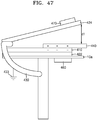
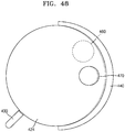
- FIG. 46 is a view illustrating a state in which the first and second charging parts 410 and 440 contact each other through a sliding motion.
- FIG. 47 is a side view illustrating the triboelectric generator illustrated in FIG. 46
- FIG. 48 is a top view illustrating the triboelectric generator illustrated in FIG. 46 .
- the first charging part 410 may move relative to the second charging part 440, and thus the surfaces of the first and second charging parts 410 and 440 may contact each other.
- the second charging part 440 slides on the surface of the first charging part 410, tribocharging may occur.
- the surfaces of the first and second charging parts 410 and 440 may be charged with opposite polarities.
- electrons move from the surface of the second charging part 440 to the surface of the first charging part 410 because of friction between the second charging part 440 and the first charging part 410.
- the second charging part 440 may be charged with a positive charge
- the first charging part 410 may be charged with a negative charge.
- electrons may move from the surface of the first charging part 410 to the surface of the second charging part 440, and thus the first charging part 410 may be charged with a positive charge and the second charging part 440 may be charged with a negative charge.
- the first and second magnetic parts 460 and 470 may be spaced further apart than shown in FIG. 45 .
- the distance d1 between the second electrode 424 and the second charging part 440 may become less than shown in FIG. 44 .
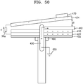
- FIG. 49 is a view illustrating a state in which the first charging part 410 is further rotated relative to the second charging part 440.
- FIG. 50 is a side view illustrating the triboelectric generator illustrated in FIG. 49
- FIG. 51 is a top view illustrating the triboelectric generator illustrated in FIG. 49 .
- the contact area between the first and second charging parts 410 and 440 may increase.
- the grounding unit 430 may rotate together with the first charging part 410 and may contact the second charging part 440. An end portion of the grounding unit 430 may contact an edge of the second charging part 440.
- the second charging part 440 and the charge reservoir 433 may be electrically connected to each other.
- the second charging part 440 may exchange charges with the charge reservoir 433.
- the second charging part 440 may receive electrons from the charge reservoir 433. If the second charging part 440 receives electrons from the charge reservoir 433, the electric potential of the second charging part 440 may become substantially equal to the electric potential of the ground.
- electrostatic induction may occur between the first and second electrodes 422 and 424.
- electrons may move from the first electrode 422 to the second electrode 424. That is, current may flow between the first and second electrodes 422 and 424.
- electric energy may be harvested from a load 30a connected between the first and second electrodes 422 and 424.
- the first electrode 422 may have a relatively large amount of positive charge
- the second electrode 424 may have a relatively large amount of negative charge. Since the second charging part 440 exchanges charges with the charge reservoir 433 through the grounding unit 430, current flowing between the first and second electrodes 422 and 424 may be amplified.
- the first and second magnetic parts 460 and 470 may be spaced further apart than shown in FIG. 48 . As the distance between the first and second magnetic parts 460 and 470 increases, the magnitude of magnetic force between the first and second magnetic parts 460 and 470 may decrease. Referring to FIG. 50 , as the magnitude of magnetic force between the first and second magnetic parts 460 and 470 decreases, the distance d1 between the second electrode 424 and the second charging part 440 may decrease.
- FIG. 52 is a view illustrating a state in which the first charging part 410 is further rotated relative to the second charging part 440.
- FIG. 53 is a side view illustrating the triboelectric generator illustrated in FIG. 52
- FIG. 54 is a top view illustrating the triboelectric generator illustrated in FIG. 52 .
- the contact area between the first and second charging parts 410 and 440 may be maximized. As the contact area between the first and second charging parts 410 and 440 increases, a large amount of negative charge may be induced on the surface of the first charging part 410. While the first charging part 410 rotates relative to the second charging part 440, the end portion of the grounding unit 430 may slide on the edge of the second charging part 440. As electrons move from the charge reservoir 433 to the second charging part 440, the electric potential of the second charging part 440 may become equal to the electric potential of the charge reservoir 433.
- electrostatic induction may occur between the first and second electrodes 422 and 424. For example, electrons may move from the first electrode 422 to the second electrode 424. Therefore, in the first electrode 422, the amount of positive charge may be greater than the amount of negative charge.
- the first and second magnetic parts 460 and 470 may be spaced further apart than shown in FIG. 51 . As the distance between the first and second magnetic parts 460 and 470 increases, the magnitude of magnetic force between the first and second magnetic parts 460 and 470 may decrease. Referring to FIG. 52 , as the magnitude of magnetic force between the first and second magnetic parts 460 and 470 decreases, the second electrode 424 and the second charging part 440 may contact each other.
- the second electrode 424 may be electrically connected to the charge reservoir 433 through the second charging part 440 and the grounding unit 430.
- the second electrode 424 may exchange charges with the charge reservoir 433.
- the electric potential of the second electrode 424 may become equal to the electric potential of the charge reservoir 433.
- the electric potential of the second electrode 424 may become substantially equal to the electric potential of the ground.
- Electrons may move from the first electrode 422 to the second electrode 424 because of the electrostatic induction between the first and second electrodes 422 and 424. As many electrons as the number of electrons moved from the first electrode 422 to the second electrode 424 may move from the second electrode 424 to the charge reservoir 433. Therefore, the second electrode 424 may be maintained in an electrically neutral state. Since the second electrode 424 is maintained in an electrically neutral state, the amount of current flowing between the first and second electrodes 422 and 424 may be amplified.
- FIG. 55 is a view illustrating a state in which the first charging part 410 is further rotated relative to the second charging part 440.
- FIG. 56 is a side view illustrating the triboelectric generator illustrated in FIG. 55
- FIG. 57 is a top view illustrating the triboelectric generator illustrated in FIG. 55 .
- the contact area between the first and second charging parts 410 and 440 may decrease.
- the second electrode 424 and the second charging part 440 may be separated from each other.
- the end portion of the grounding unit 430 may be at a position just before separation from the second charging part 440.
- the first charging part 410 may return to the initial position shown in FIGS. 43 to 45 . If the first charging part 410 returns to the initial position, there may be no movement of charge because of electrical equilibrium.
- the first charging part 410 may be maintained in a negatively charged state unlike the state shown in FIGS. 43 to 45 . If relative rotation between the first and second charging parts 410 and 440 is continued, the processes described with reference to FIGS. 46 to 57 may be repeated in the state in which the first charging part 410 is negatively charged. While the cycle is repeated, current may flow between the first and second electrodes 422 and 424 owing to electrostatic induction. While the second charging part 440 intermittently contacts the charge reservoir 433, the second charging part 440 may exchange charges with the charge reservoir 433. Since the second charging part 440 exchanges charges with the charge reservoir 433, current flowing between the first and second electrodes 422 and 424 may be amplified.
- FIG. 58 is a view illustrating a modification of the triboelectric generator shown in FIG. 44 .
- FIG. 58 the same descriptions as those given above with reference to FIGS. 43 and 57 will not be repeated.
- a plurality of protrusions may be formed on at least one of a contact surface of a first charging part 410 and a contact surface of a second charging part 440.
- the protrusions may include nano-pyramids, nano-wires, nano-balls, nano-rods, or the like. Since the protrusions are formed on at least one of the contact surface of the first charging part 410 and the contact surface of the second charging part 440, when the first charging part 410 and the second charging part 440 contact each other, the amount of charge induced on each of the contact surface of the first charging part 410 and the contact surface of the second charging part 440 may be increased.
- FIG. 59 is a view illustrating a modification of the triboelectric generator shown in FIG. 44 .
- a charge reservoir 433a may include a conductive member.
- the conductive member has a plate shape.
- the charge reservoir 433a may be a conductive member having a high degree of capacity.
- the charge reservoir 433a may exchange charges with the second charging part 440. That is, as the charge reservoir 433a exchanges charges with the second charging part 440, the electric potential of the second charging part 440 may become equal to the electric potential of the charge reservoir 433a.
- the electric potential of the charge reservoir 433a may be substantially the same as the electric potential of ground.
- FIG. 60 is a view illustrating a triboelectric system according to some example embodiments.
- a triboelectric system 1000 may include a plurality of triboelectric generators 500.
- the triboelectric generators 500 may be arranged in an array on a substrate and may be electrically connected to a common circuit.
- the substrate may be in polygonal shape, but inventive concepts are not limited thereto.
- the triboelectric generators 500 may be exposed to wind.
- the triboelectric system 1000 may be useful to place on structures where environmental wind may rotate the triboelectric generator.
- the triboelectric system 1000 may be useful on an external surface of a building and/or an external surface (e.g., the roof) of a vehicle, but inventive concepts are not limited thereto.
- the triboelectric generator 500 in FIG. 60 may include the triboelectric generator discussed with reference to FIG. 23 , but inventive concepts are not limited thereto. Any one of the triboelectric generators described above with reference to FIGS. 1 to 59 may be used as one of the triboelectric generators 500. Also, the triboelectric generators 500 in the triboelectric system may all be the same, or some of the triboelectric generators 500 may be different other triboelectric generators 500 in the triboelectric system 1000.
- FIG. 61 is a view illustrating a triboelectric system according to some example embodiments.
- a triboelectric system 2000 may include a triboelectric generator arranged (see e.g., triboelectric generator described in FIG. 2 ) arranged over a piston container 150 and a trough T (or other reflecting mirror).
- the piston container 150 may be positioned between a side of the second charging structure 140 and the trough T (other reflecting mirror).
- the trough T (other reflecting mirror) may reflect light L from the sun S (and/or other light source) to heat a fluid F in the piston container 150.
- the light L may also increase a temperature of the piston container 150 and the piston container 150 may transfer thermal energy to the fluid F.
- the second charging structure 140 may slide along the second electrode 124, grounding unit 130, and first charging structure 122.
- the base B may be configured to move with minimal friction up and down in the piston container 150.
- the volume expansion of the fluid may push the piston 145 upward and move the second charging structure 140 upward.
- the temperature of the fluid F decreases, the volume of the fluid may decrease as the fluid F changes from a gas to a liquid; thus, the piston 145 may no longer push the second electrode 124 up and the second electrode 124 may lower towards the piston container 150.
- Triboelectric generators according to some example embodiments have been described with reference to FIGS. 1 to 59 , and triboelectric systems according to some example embodiments have been described with reference to FIGS. 60-61 .
- the first and second charging parts may contact each other and may be charged with different polarities.
- current may flow between the first and second electrodes when the first and second charging parts move relative to each other. Electric energy may be harvested from current flowing between the first and second electrodes.
- the electric potential of the second charging part or the second electrode may vary as the grounding unit intermittent contacts the second charging part or the second electrode, and thus the amount of current flowing between the first and second electrodes may be amplified.
- any one of the above-described triboelectric generators may be included as an electricity supply unit in a device such as a smartwatch, a cellular phone, a radio, a biosensor, a position sensor, or another triboelectric system, a body temperature sensor, a blood pressure sensor.
- a device such as a smartwatch, a cellular phone, a radio, a biosensor, a position sensor, or another triboelectric system, a body temperature sensor, a blood pressure sensor.
- any one of the above-described triboelectric generators may be included in a mobile device configured for attachment to a body part that almost always moves, such as the hands or legs, so as to convert kinetic energy of the hands or legs into electric energy.
- any one of the above-described triboelectric generators may be included a machine to convert vibrational energy into electric energy.
- the triboelectric generators may be used to generate electric energy using vibration caused by wind, pressure, sound, or fluid flow.
Landscapes
- Engineering & Computer Science (AREA)
- Power Engineering (AREA)
- Charge And Discharge Circuits For Batteries Or The Like (AREA)
- Electrostatic Charge, Transfer And Separation In Electrography (AREA)
- Electrostatic Separation (AREA)
- Dry Development In Electrophotography (AREA)
Abstract
Description
- The present disclosure relates to triboelectric generators, and more particularly, to triboelectric generators having grounding structures.
- Recently, there is increasing interest in energy harvesting techniques. Energy harvesting devices capable of converting energy of surroundings such as mechanical energy of wind, vibration, or human body motion into electric energy and extracting the electric energy may be considered as new eco-friendly energy generating devices.
- Triboelectric generators are energy harvesting devices configured to generate electric energy using a charge transfer phenomenon occurring when two charging parts rub together. Triboelectric generators have a high degree of energy conversion efficiency, and thus if triboelectric generators are used, a high degree of output may be obtained even by a small amount of force. In addition, triboelectric generators do not have time or spatial limitations compared to energy harvesting devices using heat or sunlight, and it is possible to continuously generate electric energy using triboelectric generators unlike the case of using piezoelectric energy harvesting devices configured to generate electric energy by deforming a piezoelectric material.
- Some example embodiments provide triboelectric generators including grounding structures.
- Additional aspects will be set forth in part in the description which follows and, in part, will be apparent from the description, or may be learned by practice of the presented embodiments.
- According to some example embodiments, a triboelectric generator includes a first electrode and a second electrode spaced apart from each other, a first charging part and a second charging part, and a grounding unit. The first charging part is on the first electrode. The first charging part is configured to be charged a first polarity due to contact with the second charging part. The second charging part is configured to slide on a surface of the first charging part. The second charging part is configured to charge a second polarity that is opposite the first polarity through contact with the first charging part. The grounding unit is configured to intermittently connect the second charging part to a charge reservoir according to movement of the second charging part.
- In some example embodiments, the second charging part may be configured to slide on a surface of the second electrode as well as on the surface of the first charging part.
- In some example embodiments, the first electrode and the second electrode may be spaced apart from each other in a direction in which the second charging part is configured to slide.
- In some example embodiments, the first charging part may be on an upper surface of the first electrode, and the upper surface of the first electrode may face the second charging part.
- In some example embodiments, the grounding unit may be between the first electrode and the second electrode, and the second charging part may be configured to slide on an upper surface of the grounding unit.
- In some example embodiments, a distance between the first charging part and the grounding unit may be less than a width of the second charging part, and a distance between the second electrode and the grounding unit may be less than the width of the second charging part.
- In some example embodiments, the first electrode, the grounding unit, and the second electrode may be on a first substrate.
- In some example embodiments, the first substrate has a cylindrical shape or a circular post shape.
- In some example embodiments, the triboelectric generator may further include a second substrate having a cylindrical shape surrounding the first substrate, and the second charging part may be on an inner surface of the second substrate.
- In some example embodiments, the first substrate may have a circular plate shape, and the first electrode, the grounding unit, and the second electrode may be arranged on the first substrate in radial directions.
- In some example embodiments, the triboelectric generator may further include a second substrate having a circular plate shape facing the first substrate, and the second charging part may be on the second substrate.
- In some example embodiments, the second charging part may be configured to slide on the first charging part while rotating relative to the first charging part, and the first electrode and the second electrode may be spaced apart from each other in a direction perpendicular to a direction in which the second charging part is configured to slide.
- In some example embodiments, the first charging part may be on a lower surface of the first electrode facing the second charging part.
- In some example embodiments, the grounding unit may be electrically connected to the charge reservoir, and the grounding unit may include a conductive post configured to intermittently contact the second charging part when the second charging part rotates.
- In some example embodiments, the grounding unit may include a conductive member and an insulative member (e.g. electric insulator) alternately arranged in a direction in which the second charging part rotates, and the conductive member may be electrically connected to the charge reservoir and configured to intermittently contact the second charging part.
- In some example embodiments, the first charging part, the second charging part, and the second electrode may have a fan shape.
- In some example embodiments, the triboelectric generator may further include: a first magnetic part below the first electrode; and a second magnetic part above the second electrode.
- In some example embodiments, the second electrode may be configured to be moved relative to the second charging part by magnetic force between the first magnetic part and the second magnetic part, and mutually-facing surfaces of the first magnetic part and the second magnetic part may have a same polarity.
- In some example embodiments, the first magnetic part may be interlocked with the first electrode and the first charging part.
- In some example embodiments, a lower surface of the second charging part may be configured to contact an upper surface of the first charging part while the second charging part rotates relative to the first charging part.
- In some example embodiments, the first electrode, the first charging part, the grounding unit, and the first magnetic part may be configured to interlock with each other and to rotate relative to the second charging part.
- In some example embodiments, the second electrode and the second charging part may be configured to contact each other or to separate from each other depending on a distance between the first magnetic part and the second magnetic part.
- In some example embodiments, , the second electrode interlocked with the second magnetic part may be configured to contact an upper surface of the second charging part when the first charging part and the second charging part contact each other.
- In some example embodiments, the first charging part may be configured to be charged with a negative charge, and the second charging part may be configured to be charged with a positive charge.
- In some example embodiments, the first charging part may be charged with a positive charge, and the second charging part may be charged with a negative charge.
- In some example embodiments, the charge reservoir may include a ground or a conductive member.
- According to some example embodiments, a triboelectric generator may include a first electrode, a first charging part on the first electrode, a second electrode spaced apart from the first electrode, a second charging part configured to contact a surface of the first charging part through sliding motion, and a grounding unit configured to intermittently connect the second charging part to a charge reservoir according to movement of the second charging part. The first charging part may have a first charging rating. The first charging part may include a first material. The second charging part may have a second charging rating that is different than the first charging rating. The second charging part may include an electrically conductive material that is different than the first material.
- In some example embodiments, the grounding unit may be between the first electrode and the second electrode, and the second charging part may be configured to slide on an upper surface of the grounding unit.
- In some example embodiments, the first charging part may include at least one of an organic polymer, an inorganic polymer, an organically modified ceramic. The second charging part may include a metallic material.
- In some example embodiments, the second charging part may be configured to slide on the first charging part while rotating relative to the first charging part, and the first electrode and the second electrode may be spaced apart from each other in a direction perpendicular to a direction in which the second charging part is configured to slide.
- In some example embodiments, a distance between the first charging part and the grounding unit may be less than a width of the second charging part, and a distance between the second electrode and the grounding unit may be less than the width of the second charging part.
- These and/or other aspects will become apparent and more readily appreciated from the following description of non-limiting embodiments, taken in conjunction with the accompanying drawings in which:
-
FIG. 1 is a perspective view illustrating a triboelectric generator according to some example embodiments; -
FIG. 2 is a cross-sectional view illustrating the triboelectric generator shown inFIG. 1 ; -
FIG. 3 is a view illustrating a modification of the triboelectric generator shown inFIG. 2 ; -
FIG. 4 is a view illustrating a modification of the triboelectric generator shown inFIG. 2 ; -
FIG. 5 is a view illustrating a sliding motion of a second charging part relative to a first charging part; -
FIG. 6 is a view illustrating a state in which the second charging part meets a grounding unit as a result of a sliding motion; -
FIG. 7 is a view illustrating a state in which the second charging part is further moved relative to a substrate through a sliding motion; -
FIG. 8 is a view illustrating a state in which the second charging part meets a second electrode as a result of a sliding motion; -
FIG. 9 is a view illustrating a state in which the second charging part is further moved relative to the substrate through a sliding motion; -
FIG. 10 is a view illustrating a state in which the second charging part is separated from the second electrode as a result of a sliding motion; -
FIG. 11 is a view illustrating a state in which the second charging part approaches the first charging part; -
FIG. 12 is a view illustrating a state in which the second charging part contacts the first charging part through a sliding motion; -
FIG. 13 is a view illustrating a state in which the second charging part meets the grounding unit as a result of a sliding motion; -
FIG. 14 is a view illustrating a state in which the electric potential of the second charging part varies as a result of a flow of electrons shown inFIG. 13 ; -
FIG. 15 is a view illustrating a state in which the second charging part is further moved relative to the substrate through a sliding motion; -
FIG. 16 is a view illustrating a state in which the second charging part contacts the second electrode as a result of a sliding motion; -
FIG. 17 is a view illustrating a state in which the second charging part is separated from the second electrode as a result of a sliding motion in the state shown inFIG. 16 ; -
FIG. 18 is a perspective view illustrating a triboelectric generator having a different shape according to some example embodiments; -
FIG. 19 is a perspective view illustrating a triboelectric generator having a different shape according to some example embodiments; -
FIG. 20 is a perspective view illustrating a triboelectric generator having a different shape according to some example embodiments. -
FIG. 21 is a perspective view illustrating a triboelectric generator having a different shape according to some example embodiments; -
FIG. 22 is a perspective view illustrating a triboelectric generator having a different shape according to some example embodiments; -
FIG. 23 is illustrates a triboelectric generator having a different shape according to some example embodiments; -
FIG. 24 is a schematic cross-sectional view illustrating a triboelectric generator according to some example embodiments; -
FIG. 25 is a view illustrating a state in which first and second charging parts are in contact with each other; -
FIG. 26 is a view illustrating a state in which the second charging part contacts a grounding unit; -
FIG. 27 is a view illustrating a state in which the second charging part contacts a second electrode; -
FIGS. 28 and 29 are views illustrating the second charging part separating from the second electrode and the first charging part; -
FIG. 30 is a view illustrating a modification of the triboelectric generator shown inFIG. 23 ; -
FIG. 31 is a cross-sectional view illustrating a triboelectric generator according to some example embodiments; -
FIG. 32 is a view illustrating a modification of the triboelectric generator shown inFIG. 31 ; -
FIG. 33 is a view illustrating a state in which first and second charging parts shown inFIG. 31 are in contact with each other; -
FIG. 34 is a view illustrating a state in which the second charging part is moved relative to the first charging part through a sliding motion; -
FIG. 35 is a view illustrating a state in which the second charging part contacts a grounding unit through a sliding motion; -
FIG. 36 is a view illustrating a state in which the second charging part approaches again the first charging part after the cycle described with reference toFIGS. 31 to 34 is completed; -
FIG. 37 is a view illustrating a state in which the second charging part contacts the first charging part as a result of a sliding motion; -
FIG. 38 is a view illustrating a state in which the second charging part is moved relative to the first charging part through a sliding motion; -
FIG. 39 is a view illustrating a state in which the second charging part contacts the grounding unit through a sliding motion; -
FIG. 40 is a current-time graph of the triboelectric generator shown inFIGS. 1 to 17 , illustrating current flowing between first and second electrodes, and current flowing in the grounding unit; -
FIG. 41 is a graph for comparing an output current measured between the first and second electrodes of the triboelectric generator shown inFIGS. 1 to 17 with an output current measured between the first and second electrodes of the triboelectric generator after the grounding unit was removed from the triboelectric generator; -
FIG. 42 is a graph for comparing a voltage measured between the first and second electrodes of the triboelectric generator shown inFIGS. 1 to 17 with a voltage measured between the first and second electrodes of the triboelectric generator after the grounding unit was removed from the triboelectric generator; -
FIG. 43 is a perspective view illustrating a triboelectric generator according to some example embodiments; -
FIG. 44 is a side view illustrating the triboelectric generator shown inFIG. 43 ; -
FIG. 45 is a top view illustrating the triboelectric generator shown inFIG. 43 ; -
FIG. 46 is a view illustrating a state in which first and second charging parts contact each other as a result of a sliding motion; -
FIG. 47 is a side view illustrating the triboelectric generator shown inFIG. 46 ; -
FIG. 48 is a top view illustrating the triboelectric generator shown inFIG. 46 ; -
FIG. 49 is a view illustrating a state in which the first charging part is further rotated relative to the second charging part; -
FIG. 50 is a side view illustrating the triboelectric generator shown inFIG. 49 ; -
FIG. 51 is a top view illustrating the triboelectric generator shown inFIG. 49 ; -
FIG. 52 is a view illustrating a state in which the first charging part is further rotated relative to the second charging part; -
FIG. 53 is a side view illustrating the triboelectric generator shown inFIG. 52 ; -
FIG. 54 is a top view illustrating the triboelectric generator shown inFIG. 52 ; -
FIG. 55 is a view illustrating a state in which the first charging part is further rotated relative to the second charging part; -
FIG. 56 is a side view illustrating the triboelectric generator shown inFIG. 55 ; -
FIG. 57 is a top view illustrating the triboelectric generator shown inFIG. 55 ; -
FIG. 58 is a view illustrating a modification of the triboelectric generator shown inFIG. 44 ; -
FIG. 59 is a view illustrating a modification of the triboelectric generator shown inFIG. 44 ; -
FIG. 60 is a view illustrating a triboelectric system according to some example embodiments; and -
FIG. 61 is a view illustrating a triboelectric system according to some example embodiments. - Reference will now be made in detail to some example embodiments illustrated in the accompanying drawings, wherein like reference numerals refer to like elements throughout. In this regard, the present embodiments may have different forms and should not be construed as being limited to the descriptions set forth herein. Accordingly, the embodiments are merely described below, by referring to the figures, to explain aspects. As used herein, the term "and/or" includes any and all combinations of one or more of the associated listed items. Expressions such as "at least one of," when preceding a list of elements, modify the entire list of elements and do not modify the individual elements of the list.
- The terms used in the present disclosure are general terms currently widely used in the art in consideration of functions regarding inventive concepts, but the terms may vary according to the intention of those of ordinary skill in the art, precedents, or new technology in the art. Also, some terms may be arbitrarily selected by the applicant, and in this case, the meaning of the selected terms will be described in the detailed description of the present disclosure. Thus, the terms used herein should not be construed based on only the names of the terms but should be construed based on the meaning of the terms together with the description throughout the present disclosure.
- In the following descriptions of embodiments, when a portion or element is referred to as being connected to another portion or element, the portion or element may be directly connected to the other portion or element, or may be electrically connected to the other portion or elements with intervening portions or elements being therebetween. It will be further understood that the terms "comprises" and/or "comprising" used herein specify the presence of stated features or elements, but do not preclude the presence or addition of one or more other features or elements. In the descriptions of the embodiments, terms such as unit or module are used to denote a unit having at least one function or operation and implemented with hardware, software, or a combination of hardware and software.
- In the following descriptions of the embodiments, expressions or terms such as "constituted by," "formed by," "include," "comprise," "including," and "comprising" should not be construed as always including all specified elements, processes, or operations, but may be construed as not including some of the specified elements, processes, or operations, or further including other elements, processes, or operations.
- In addition, although the terms "first" and "second" are used to describe various elements, these elements should not be limited by these terms. These terms are only used to distinguish one element from other elements.
- The following descriptions of the embodiments should not be construed as limiting the scope of inventive concepts, and modifications or changes that could be easily made from the embodiments by those of ordinary skill in the art should be construed as being included in the scope of inventive concepts. Hereinafter, example embodiments will be described with reference to the accompanying drawings.
-
FIG. 1 is a perspective view illustrating a triboelectric generator according to some example embodiments.FIG. 2 is a cross-sectional view illustrating the triboelectric generator shown inFIG. 1 . - Referring to
FIGS. 1 and 2 , the triboelectric generator may include afirst electrode 122 and asecond electrode 124 spaced apart from each other, afirst charging part 110 disposed on a surface S1 of thefirst electrode 122, asecond charging part 140 slidable in a direction (x-axis direction) on a surface S2 of thefirst charging part 110 and a surface S3 of thesecond electrode 124, and agrounding unit 130 configured to intermittently connect thesecond charging part 140 to acharge reservoir 133 according to the movement of thesecond charging part 140. The triboelectric generator may include a sliding mechanism to induce a horizontal motion of thesecond charging part 140 relative to thefirst charging part 110 or thesecond electrode 124 by an externally applied force and thus to bring adjacent surfaces into contact with each other. - The
second charging part 140 may rub on an upper surface of thefirst charging part 110 through a sliding motion. Here, the expression "thesecond charging part 140 slides" refers to that thesecond charging part 140 moves relative to thefirst charging part 110, thegrounding unit 130, and thesecond electrode 124. Therefore, sliding of thesecond charging part 140 may occur as thesecond charging part 140 moves. In addition, sliding of thesecond charging part 140 may occur as thefirst charging part 110, thegrounding unit 130, and thesecond electrode 124 move relative to thesecond charging part 140. In addition, the expression "thesecond charging part 140 slides in a direction" refers to that thesecond charging part 140 slides in a direction in which thefirst charging part 110, thegrounding unit 130, and thesecond electrode 124 are arranged. Therefore, the movement of thesecond charging part 140 is not limited to straight movement. - The
first charging part 110 may include a first material. Thesecond charging part 140 may include a second material that is a different material than the first material. For example, thesecond charging part 140 and thefirst charging part 110 may include materials having different charging ratings. Therefore, if a surface of thesecond charging part 140 is rubbed against the surface S2 of thefirst charging part 110, the surface S2 of thefirst charging part 110 and the surface of thesecond charging part 140 may be charged with different polarities. The types of charges of thefirst charging part 110 and thesecond charging part 140 are dependent on materials of thefirst charging part 110 and thesecond charging part 140, for example, may be determined by relative positions of the materials of thefirst charging part 110 and thesecond charging part 140 in a triboelectric series. - For example, the surface S2 of the
first charging part 110 may be charged with a negative charge by friction with thesecond charging part 140, and the surface of thesecond charging part 140 may be charged with a positive charge by friction with thefirst charging part 110. Thesecond charging part 140 may include a conductive material for easy electric connection with thegrounding unit 130. The conductive material may include a metallic material that is easily charged by friction, such as aluminum (Al), copper (Cu), gold (Au), or steel. In addition, thefirst charging part 110 may include at least one of polytetrafluoroethylene (Teflon), fluorinated ethylene propylene (FEP), poly(methyl methacrylate) (PMMA), polyvinylidene fluoride (PVDF), polycarbonate (PC), polyvinyl chloride (PVC), polyimide (Kapton), polypropylene (PP), polyethylene (PE), and polystyrene (PS) that are easily charged with a negative charge by friction with the conductive material of thesecond charging part 140. In addition, thefirst charging part 110 may include an organic polymer such as poly(methyl methacrylate) PMMA, polyethylene terephthalate (PET), polyetheretherketone (PEEK), cycloolefin copolymer (COC), or polytetrafluoroethylene (PTFE). Thefirst charging part 110 may include an inorganic polymer such as polydimethylsiloxane (PDMS) or organically modified ceramic (ORMOCER). The above-listed materials are examples, and inventive concepts are not limited thereto. - In another example, the surface S2 of the
first charging part 110 may be charged with a positive charge by friction with thesecond charging part 140, and the surface of thesecond charging part 140 may be charged with a negative charge by friction with thefirst charging part 110. Thesecond charging part 140 may include a conductive material for easy electric connection with thegrounding unit 130. The conductive material may include at least one of aluminum (Al), copper (Cu), gold and steel that are easily charged by friction. Thefirst charging part 110 may include at least one of polyformaldehyde, ethylcellulose, polyamide, melamine formol, wool, silk, mica, and nylon that are easily charged with a positive charge by friction with the conductive material. The above-listed materials are examples, and inventive concepts are not limited thereto. - At least one of the first and second charging
parts - Examples of a source of the n-type dopant may include a reduction product of a substituted or unsubstituted nicotinamide; a reduction product of a compound which is chemically bound to a substituted or unsubstituted nicotinamide; and a compound including at least two pyridinium moieties in which a nitrogen atom of at least one of the pyridinium moieties is reduced. For example, the source of the n-type dopant may include nicotinamide mononucleotide-H (NMNH), nicotinamide adenine dinucleotide-H (NADH), nicotinamide adenine dinucleotide phosphate-H (NADPH), or viologen. Alternatively, the source of the n-type dopant may include a polymer such as polyethyleneimine (PEI). Alternatively, the n-type dopant may include an alkali metal such as potassium (K) or lithium (Li). The above-listed p-type dopant materials and n-type dopant materials are examples. That is, any other materials may be used as the p-type dopant and the n-type dopant.
- The
grounding unit 130 may be electrically connected to thecharge reservoir 133. Thecharge reservoir 133 may include ground or a conductive member having substantially no variation in electric potential. When thesecond charging part 140 contacts thegrounding unit 130, thecharge reservoir 133 and thesecond charging part 140 may be electrically connected to each other through thegrounding unit 130. If thesecond charging part 140 is connected to thecharge reservoir 133 through thegrounding unit 130, the electric potential of thesecond charging part 140 may become substantially equal to the electric potential of thecharge reservoir 133. - The first and
second electrodes second charging part 140 slides. The first andsecond electrodes second electrodes second electrodes - Electrostatic induction may occur between the first and
second electrodes second charging part 140 slides. That is, while thesecond charging part 140 slides, charge may flow between the first andsecond electrodes second electrodes -
FIG. 3 illustrates a modification of the triboelectric generator illustrated inFIGS. 1 and 2 , according to some example embodiments. In the following description with reference toFIG. 3 , the same descriptions as those given above with reference toFIGS. 1 and 2 will not be repeated. - Referring to
FIG. 3 , a plurality of protrusions may be formed on at least one of contact surfaces between thefirst charging part 110 and thesecond charging part 140. The protrusions may include nano-pyramids, nano-wires, nano-balls, nano-rods, or the like. Since the protrusions are formed on at least one of the contact surfaces between thefirst charging part 110 and thesecond charging part 140, when thefirst charging part 110 and thesecond charging part 140 are brought into contact with each other, the amount of charge induced on each of the contact surface of thefirst charging part 110 and the contact surface of thesecond charging part 140 may be increased. -
FIG. 4 illustrates a modification of the triboelectric generator illustrated inFIGS. 1 and 2 , according to some example embodiments. - Referring to
FIG. 4 , a charge reservoir may include a conductive member 131. InFIG. 4 , theconductive member 133a has a plate shape. However, this is an example, and theconductive member 133a is not limited thereto. The charge reservoir may be a conductive member having a high degree of capacity. If the charge reservoir is connected to thesecond charging part 140 through thegrounding unit 130, the charge reservoir may exchange charges with thesecond charging part 140. That is, the charge reservoir may vary the electric potential of thesecond charging part 140 by exchanging charges with thesecond charging part 140. For example, the electric potential of the charge reservoir may be substantially the same as the electric potential of ground. - Hereinafter, an energy harvesting process using the triboelectric generator illustrated in
FIGS. 1 and 2 will be described. -
FIG. 5 is a view illustrating a state in which thesecond charging part 140 is moved relative to thefirst charging part 110 through a sliding motion. In the following description, charges illustrated in the drawings are examples. That is, there may be various flows of charge in triboelectric generators of various embodiments. - The first and second charging
parts second charging part 140 may occur by the movement of thesecond charging part 140, thefirst charging part 110, or both the first and second chargingparts second electrodes grounding unit 130 may be arranged on afirst substrate 10. Thegrounding unit 130 may be disposed between the first andsecond electrodes second charging part 140 moves relative to thefirst substrate 10, thesecond charging part 140 may sequentially make contact with surfaces of thefirst charging part 110, thegrounding unit 130, and thesecond electrode 124. - When the
second charging part 140 and thefirst charging part 110 make contact with each other, the first and second chargingparts FIG. 5 , electrons move from the surface of thesecond charging part 140 to the surface of thefirst charging part 110 because of friction between thesecond charging part 140 and thefirst charging part 110. Owing to the movement of electrons, thesecond charging part 140 may be charged with a positive charge, and thefirst charging part 110 may be charged with a negative charge. However, this is merely an example. That is, the opposite case may also be possible. For example, electrons may move from the surface of thefirst charging part 110 to the surface of thesecond charging part 140, and thus thefirst charging part 110 may be charged with a positive charge and thesecond charging part 140 may be charged with a negative charge. -
FIG. 6 is a view illustrating a state in which thesecond charging part 140 meets thegrounding unit 130 as a result of a sliding motion. - Referring to
FIG. 6 , thesecond charging part 140 may be brought into contact with an upper surface of thegrounding unit 130 through a sliding motion. Since a portion of the upper surface of thefirst charging part 110 is not in contact with thesecond charging part 140, electrostatic induction may occur between the first andsecond electrodes first electrode 122 to thesecond electrode 124 because of the electrostatic induction. While current flows between the first andsecond electrodes load 30 between the first andsecond electrodes - The distance d1 between the
first charging part 110 and thegrounding unit 130 may be less than the width W of thesecond charging part 140. Here, the width W of thesecond charging part 140 refers to a length of thesecond charging part 140 in the sliding direction of thesecond charging part 140. Since the width W of thesecond charging part 140 is greater than the distance d1 between thefirst electrode 122 and thegrounding unit 130, thesecond charging part 140 may contact both thefirst charging part 110 and thegrounding unit 130 at the same time. Therefore, while current flows between the first andsecond electrodes second charging part 140 through thegrounding unit 130, and thus the electric potential of thesecond charging part 140 may vary. In this case, since external electrons are introduced into thesecond charging part 140, electrostatic induction between the first andsecond electrodes first charging part 110 and thegrounding unit 130 may be greater than the width W of thesecond charging part 140. In this case, thesecond charging part 140 may make contact with thegrounding unit 130 after separating from thefirst charging part 110. - If the
second charging part 140 is brought into contact with thegrounding unit 130, thesecond charging part 140 may be electrically connected to thecharge reservoir 133. Thesecond charging part 140 may include a conductive material for easy electric connection. If thesecond charging part 140 is brought into contact with thegrounding unit 130, thesecond charging part 140 and thecharge reservoir 133 may exchange charges with each other. Owing to this exchange of charges, the electric potential of thesecond charging part 140 may become equal to the electric potential of thecharge reservoir 133. For example, if the electric potential of thecharge reservoir 133 is equal to the electric potential of the ground, thecharge reservoir 133 may supply electrons to thesecond charging part 140 through thegrounding unit 130. -
FIG. 7 is a view illustrating a state in which thesecond charging part 140 is further moved relative to thefirst substrate 10 through a sliding motion. - Referring to
FIG. 7 , the contact area between thesecond charging part 140 and thefirst charging part 110 may gradually decrease because of sliding. As the contact area between thesecond charging part 140 and thefirst charging part 110 decreases, electrostatic induction may occur between the first andsecond electrodes second electrodes second charging part 140 may be maintained to be close to the electric potential of the ground. -
FIG. 8 is a view illustrating a state in which thesecond charging part 140 meets thesecond electrode 124 as a result of a sliding motion. - Referring to
FIG. 8 , the first and second chargingparts second charging part 140 may make contact with thegrounding unit 130 and thesecond electrode 124. To allow thesecond charging part 140 to contact both thegrounding unit 130 and thesecond electrode 124, the distance d2 between thegrounding unit 130 and thesecond electrode 124 may be less than the width W of thesecond charging part 140. - When the
second charging part 140 contacts thegrounding unit 130 and thesecond electrode 124, the electric potential of thesecond electrode 124 may vary because of thecharge reservoir 133. For example, as a negative charge of thesecond electrode 124 moves to thecharge reservoir 133 through thesecond charging part 140 and thegrounding unit 130, the electric potential of thesecond electrode 124 may become substantially equal to the electric potential of the ground. -
FIG. 9 is a view illustrating a state in which thesecond charging part 140 is further moved relative to thefirst substrate 10 as a result of sliding. - Referring to
FIG. 9 , as electrons move from thesecond electrode 124 to thegrounding unit 130, the electric potential of thesecond charging part 140 and thesecond electrode 124 may become substantially equal to the electric potential of the ground. -
FIG. 10 is a view illustrating a state in which thesecond charging part 140 is separate from thesecond electrode 124 as a result of a sliding motion. - Referring to
FIG. 10 , as thesecond charging part 140 is separated from thesecond electrode 124, a first cycle illustrated with reference toFIGS. 5 to 10 may terminate. After the first cycle terminates, thefirst charging part 110 may be maintained in a negatively charged state. Thefirst electrode 122 may have a relatively large amount of positive charge compared to the amount of negative charge because of the influence of negative charge of thefirst charging part 110. After charge equilibrium is established as illustrated inFIG. 10 , there may be substantially no movement of charge until the next cycle in which thesecond charging part 140 and thefirst charging part 110 meet each other. In addition, since the next cycle starts after thesecond charging part 140 and thesecond electrode 124 have the electric potential of the ground, a larger amount of electric energy may be obtained in the next cycle. - Hereinafter, an explanation will be given of a process of harvesting energy in cycles after the first cycle described with reference to
FIGS. 5 to 10 . -
FIG. 11 is a view illustrating a state in which thesecond charging part 140 approaches thefirst charging part 110. - Referring to
FIG. 11 , thefirst charging part 110 may already have a negative charge unlike the case described with reference toFIG. 5 . -
FIG. 12 is a view illustrating a state in which thesecond charging part 140 contacts thefirst charging part 110 through a sliding motion. - Referring to
FIG. 12 , since thefirst charging part 110 is already in a charged state, the amount of electron exchange between the first and second chargingparts second charging part 140 may be affected by the negative charge distributed on the surface of thefirst charging part 110. A positive charge may be induced on a lower surface of thesecond charging part 140, and a negative charge may be induced on an upper surface of thesecond charging part 140. -
FIG. 13 is a view illustrating a state in which thesecond charging part 140 meets thegrounding unit 130 as a result of a sliding motion. - When the
second charging part 140 contacts thegrounding unit 130, the electric potential of thesecond charging part 140 may vary to the electric potential of the ground. In this process, electrons may move from thesecond charging part 140 to thegrounding unit 130. -
FIG. 14 is a view illustrating a state in which the electric potential of thesecond charging part 140 is varied by the flow of electrons illustrated inFIG. 13 . - Referring to
FIG. 14 , a positive charge may remain in a portion of thesecond charging part 140 making contact with thefirst charging part 110. The remaining positive charge of thesecond charging part 140 may be balanced with the negative charge on the surface of thefirst charging part 110, and thus the electric potential of thesecond charging part 140 may become equal to the electric potential of the ground. In addition, as electrons move from thesecond charging part 140 to thegrounding unit 130, the amount of positive charge may be greater than the amount of negative charge in thesecond charging part 140. - Since a portion of the upper surface of the
first charging part 110 is not in contact with thesecond charging part 140, electrostatic induction may occur between the first andsecond electrodes second electrode 124 to thefirst electrode 122 for electrical equilibrium. As electrons flow between the first andsecond electrodes load 30 between the first andsecond electrodes -
FIG. 15 is a view illustrating a state in which thesecond charging part 140 is further moved relative to thefirst substrate 10 as a result of a sliding motion. - Referring to
FIG. 15 , as the contact area between thesecond charging part 140 and thefirst charging part 110 decreases, electrons may move from thefirst electrode 122 to thesecond electrode 124. In addition, electrons may move from thecharge reservoir 133 to thesecond charging part 140, maintaining the electric potential of thesecond charging part 140 to be equal to the electric potential of the ground. Since thesecond charging part 140 receives an external charge through thegrounding unit 130, the amount of energy harvest through theload 30 may be amplified during sliding of thesecond charging part 140. -
FIG. 16 is a view illustrating a state in which thesecond charging part 140 is in contact with thesecond electrode 124 as a result of a sliding motion. - Referring to
FIG. 16 , the first and second chargingparts second charging part 140 may make contact with thegrounding unit 130 and thesecond electrode 124. To allow thesecond charging part 140 to contact both thegrounding unit 130 and thesecond electrode 124, the distance d2 between thegrounding unit 130 and thesecond electrode 124 may be less than the width W of thesecond charging part 140. Thesecond electrode 124 may be connected to thecharge reservoir 133 through thesecond charging part 140 and thegrounding unit 130. As electrons move from thecharge reservoir 133 to thesecond electrode 124, the electric potential of thesecond electrode 124 may become equal to the electric potential of thecharge reservoir 133. For example, the electric potential of thesecond electrode 124 may become substantially equal to the electric potential of the ground. -
FIG. 17 is a view illustrating a state in which thesecond charging part 140 is separate from thesecond electrode 124 as a result of a sliding motion in the state shown inFIG. 16 . - Referring to
FIG. 17 , as thesecond charging part 140 separates from thesecond electrode 124, the cycle illustrated with reference toFIGS. 11 to 16 may terminate. Referring toFIG. 17 , after the processes described with reference toFIGS. 11 to 16 , the first and second chargingparts second electrodes FIG. 11 . Therefore, if thesecond charging part 140 is slid again on the upper surface of thefirst charging part 110, the processes described with reference toFIGS. 11 to 16 may be repeated. Thus, while the cycle is repeated, electric energy may be harvested from current flowing between the first andsecond electrodes second charging part 140 is moved relative to other members by a sliding motion, thegrounding unit 130 may exchange charges with thesecond charging part 140 and thesecond electrode 124. Since thesecond charging part 140 and thesecond electrode 124 exchange charges with thecharge reservoir 133, which is an external device, the amount of electric energy harvest may be increased during sliding cycles. - In
FIG. 1 , the first andsecond electrodes first charging part 110, and thegrounding unit 130 are disposed on thefirst substrate 10 having a flat shape. However, inventive concepts are not limited thereto. For example, thefirst substrate 10 may have any other shape to easily repeat the cycles illustrated with reference toFIGS. 1 to 17 . -
FIG. 18 is a perspective view illustrating a triboelectric generator having a different shape, according to some example embodiments. - Referring to
FIG. 18 , the triboelectric generator may include afirst substrate 10 having a circular plate shape. Afirst electrode 122, agrounding unit 130, and asecond electrode 124 may be arranged on thefirst substrate 10 in radial directions. In addition, afirst charging part 110 may be placed on an upper surface of thefirst electrode 122. For example, thefirst electrode 122, thefirst charging part 110, thegrounding unit 130, and thesecond electrode 124 may have a fan shape. However, inventive concepts are not limited thereto. - A
second charging part 140 may face an upper surface of thefirst substrate 10 and may be rotatable relative to thefirst substrate 10. For example, the triboelectric generator may further include asecond substrate 12 on which thesecond charging part 140 is disposed. Thesecond substrate 12 may have a circular plate shape. When at least one of the first andsecond substrates second charging part 140 may slide on upper surfaces of thefirst charging part 110, thegrounding unit 130, and thesecond electrode 124. However, inventive concepts are not limited thereto. For example, the triboelectric generator may not include thesecond substrate 12. For example, a rotation center of thesecond charging part 140 may be connected to thefirst substrate 10 so that thesecond charging part 140 may be slid on the upper surfaces of thefirst charging part 110, thegrounding unit 130, and thesecond electrode 124. - In
FIG. 18 , thefirst electrode 122, thegrounding unit 130, and thesecond electrode 124 are arranged on thefirst substrate 10. However, inventive concepts are not limited thereto. For example, a plurality of sets each including afirst electrode 122, agrounding unit 130, and asecond electrode 124 may be disposed on thefirst substrate 10. Similarly, a plurality of second chargingparts 140 may be disposed on thesecond substrate 12. -
FIG. 19 is a perspective view illustrating a triboelectric generator having a different shape, according to some example embodiments. - Referring to
FIG. 19 , the triboelectric generator may include afirst substrate 10 and asecond substrate 12 that have a circular plate shape. Afirst electrode 122 and asecond electrode 124 may be arranged on thefirst substrate 10 in radial directions. In addition, afirst charging part 110 may be placed on an upper surface of thefirst electrode 122. In addition, agrounding unit 130 may be placed on thesecond substrate 12. - A rotation center of a
second charging part 140 may be connected to the first andsecond substrates second charging part 140 may move between the first andsecond substrates second charging part 140 moves relative to the first andsecond substrates second charging part 140 may sequentially slide on surfaces of thefirst charging part 110, thegrounding unit 130, and thesecond electrode 124. -
FIG. 20 is a perspective view illustrating a triboelectric generator having a different shape, according to some example embodiments. - Referring to
FIG. 20 , the triboelectric generator may include afirst substrate 10 having a circular plate shape. Afirst electrode 122 and asecond electrode 124 may be arranged on thefirst substrate 10 in radial directions. In addition, afirst charging part 110 may be placed on an upper surface of thefirst electrode 122. - The triboelectric generator may include a ring having a
conductive material portion 132 and an insulative (e.g. insulating)material portion 134. Theconductive material portion 132 may be electrically connected to acharge reservoir 133 so as to function as a grounding unit. Asecond charging part 140 may slide on an inner circumferential surface of the ring through a rotation motion relative to the ring. While thesecond charging part 140 slides on an inner circumferential surface of theinsulative material portion 134, thecharge reservoir 133 and thesecond charging part 140 may not be electrically connected to each other. While thesecond charging part 140 slides on an inner circumferential surface of theconductive material portion 132, thecharge reservoir 133 and thesecond charging part 140 may be electrically connected to each other. Theconductive material portion 132 may be located between thefirst charging part 110 and thesecond charging part 140. -
FIG. 21 is a perspective view illustrating a triboelectric generator having a different shape, according to some example embodiments. - Referring to
FIG. 21 , the triboelectric generator may include afirst substrate 10 having a circular plate shape. Afirst electrode 122 and asecond electrode 124 may be arranged on thefirst substrate 10 in radial directions. In addition, afirst charging part 110 may be placed on an upper surface of thefirst electrode 122. - The triboelectric generator may include a
cylindrical case 40 having aconductive material portion 132 and an insulative material portion134. Theconductive material portion 132 may be electrically connected to acharge reservoir 133 so as to function as a grounding unit. Asecond charging part 140 may slide on an inner wall of thecase 40 through a rotation motion relative to thecase 40. While thesecond charging part 140 slides on an inner wall of theinsulative material portion 134, thecharge reservoir 133 and thesecond charging part 140 may not be electrically connected to each other. While thesecond charging part 140 slides on an inner wall of theconductive material portion 132, thecharge reservoir 133 and thesecond charging part 140 may be electrically connected to each other. Theconductive material portion 132 may be located between thefirst charging part 110 and thesecond charging part 140. -
FIG. 22 is a cross-sectional view illustrating a triboelectric generator having a different shape, according to some example embodiments. - Referring to
FIG. 22 , the triboelectric generator may include athird substrate 16 on which afirst electrode 122, agrounding unit 130, and asecond electrode 124 are arranged. Thethird substrate 16 may have a circular post shape. Although thethird substrate 16 is illustrated as having a circular post shape inFIG. 22 , inventive concepts are not limited thereto. For example, thethird substrate 16 may have a hollow cylindrical shape. Thefirst electrode 122, thegrounding unit 130, and thesecond electrode 124 may be disposed on an outer surface S4 of thethird substrate 16. Thegrounding unit 130 may be connected to acharge reservoir 133. In addition, afirst charging part 110 may be disposed on an upper surface of thefirst electrode 122. - A
second charging part 140 may move while facing the outer surface S4 of thefirst substrate 10. The triboelectric generator may further include afourth substrate 18 on which thesecond charging part 140 is disposed. For example, thesecond charging part 140 may be disposed on an inner surface S5 of thefourth substrate 18. When at least one of the third andfourth substrates second charging part 140 may sequentially slide on upper surfaces of thefirst charging part 110, thegrounding unit 130, and thesecond electrode 124. In this manner, the cycles described with reference toFIGS. 5 to 17 may be repeated. - In
FIG. 22 , thefirst electrode 122, thegrounding unit 130, and thesecond electrode 124 are arranged on thethird substrate 16. However, inventive concepts are not limited thereto. For example, a plurality of sets each including afirst electrode 122, agrounding unit 130, and asecond electrode 124 may be disposed on the outer surface S4 of thethird substrate 16. Similarly, a plurality of second chargingparts 140 may be disposed on the inner surface S5 of thesecond substrate 12. - In addition, unlike the structure shown in
FIG. 22 , thesecond charging parts 140 may be disposed on the outer surface S4 of thethird substrate 16, and thefirst electrode 122, thefirst charging part 110, thegrounding unit 130, and thesecond electrode 124 may be disposed on the inner surface S5 of thefourth substrate 18. -
FIG. 23 illustrates a triboelectric generator having a different shape, according to some example embodiments. - Referring to
FIG. 23 , asecond charging part 240 may be slid on afirst charging part 210 while being rotated relative to thefirst charging part 210. Thesecond charging part 240 may slide on surfaces of thefirst charging part 210 and asecond electrode 224 at a position between thefirst charging part 210 and thesecond electrode 224. Afirst electrode 222 and thesecond electrode 224 may be spaced apart from each other in a direction in which thesecond charging part 240 slides. - The
first charging part 210 may be disposed on a lower surface of thefirst electrode 222 facing thesecond charging part 240. Thesecond charging part 240 may face thefirst charging part 210 and may intermittently contact thefirst charging part 210 through a sliding motion. In addition, thesecond charging part 240 may intermittently contact thesecond electrode 224 through a sliding motion. Agrounding unit 230 may include a conductive post. Thegrounding unit 230 may be electrically connected to acharge reservoir 233, and when thesecond charging part 240 rotates, thegrounding unit 230 may intermittently contact thesecond charging part 240. For example, thesecond charging part 240 may includeprotrusions 242 on outer surfaces thereof. When thesecond charging part 240 rotates, theprotrusions 242 may intermittently contact thegrounding unit 230. - Each of the first and second charging
parts second electrodes parts second electrodes - Hereinafter, operations of the triboelectric generator illustrated in
FIG. 23 will be described. In the following drawings, only one of the plurality of wings of each of the first and second chargingparts second electrodes -
FIG. 24 is a schematic cross-sectional view illustrating the triboelectric generator according to some example embodiments. - Referring to
FIG. 24 , thesecond charging part 240 may be separate from thegrounding unit 230, thesecond electrode 224, and thefirst charging part 210. Thefirst charging part 210 may move in interlock with thefirst electrode 222. Thefirst charging part 210 may approach thesecond charging part 240 as a result of a relative movement. -
FIG. 25 is a view illustrating a state in which the first and second chargingparts - Referring to
FIG. 25 , the first and second chargingparts parts parts parts parts parts -
FIG. 26 is a view illustrating a state in which thesecond charging part 240 is in contact with thegrounding unit 230. - Referring to
FIG. 26 , while the first and second chargingparts protrusion 242 of thesecond charging part 240 may contact thegrounding unit 230. When thesecond charging part 240 is electrically connected to thegrounding unit 230, the electric potentials of thesecond charging part 240 and thecharge reservoir 233 may become equal to each other. For example, the electric potential of thesecond charging part 240 may become substantially equal to the electric potential of ground. -
FIG. 27 is a view illustrating a state in which thesecond charging part 240 is in contact with thesecond electrode 224. - Referring to
FIG. 27 , thesecond charging part 240 may contact thesecond electrode 224 through a sliding motion. When thesecond charging part 240 contacts thesecond electrode 224, the electric potential of thesecond electrode 224 may also become equal to the electric potential of the ground. -
FIGS. 28 and 29 are views illustrating thesecond charging part 240 separating from thesecond electrode 224 and thefirst charging part 210. - In the example shown in
FIGS. 28 and 29 , thesecond charging part 240 first separates from thesecond electrode 224. However, inventive concepts are not limited thereto. For example, thesecond charging part 240 may first separate from thefirst charging part 210 and may then separate from thesecond electrode 224. In another example, thesecond charging part 240 may separate from thefirst charging part 210 and thesecond electrode 224 substantially at the same time. Thereafter, as shown inFIG. 29 , thesecond charging part 240 may separate from thegrounding unit 230. - If the
second charging part 240 separates from thesecond electrode 224, the electric potential of thesecond electrode 224 may not be equal to the electric potential of the ground. In addition, as thesecond charging part 240 separates from thefirst charging part 210, the first andsecond electrodes second electrodes second electrodes second electrodes load 30 between the first andsecond electrodes FIGS. 24 to 29 , thesecond charging part 240 and thesecond electrode 224 may exchange charges with the outside through thegrounding unit 230, and thus the amount of current flowing between the first andsecond electrodes FIG. 29 , thefirst charging part 210, thesecond charging part 240, thesecond electrode 224, and thegrounding unit 230 are all separate from each other. From this state, the processes described with reference toFIGS. 24 to 29 may be repeated. -
FIG. 30 is a view illustrating a modification of the triboelectric generator shown inFIG. 23 . - Referring to
FIG. 30 , a grounding unit may includeconductive members 232 andinsulative members 234 alternately arranged in a direction in which asecond charging part 240 rotates. Theconductive members 232 may be electrically connected to acharge reservoir 233, and when thesecond charging part 240 rotates, theconductive members 232 may intermittently contact thesecond charging part 240 for example, theconductive members 232 and theinsulative members 234 may be disposed on an inner wall of acylindrical case 50. The distribution of theconductive members 232 may be determined such that theconductive members 232 may contact thesecond charging part 240 in the same regions as the regions in which thesecond charging part 240 and thegrounding unit 230 illustrated inFIGS. 26 to 28 contact each other. -
FIG. 31 is a cross-sectional view illustrating a triboelectric generator according to some example embodiments. - Referring to
FIG. 31 , the triboelectric generator may include: afirst electrode 322 and asecond electrode 324 spaced apart from each other; afirst charging part 310 disposed on a lower surface of thefirst electrode 322; asecond charging part 340 configured to slide in a direction (x-axis direction) while facing a lower surface of thefirst charging part 310, so as to be charged with a polarity opposite to that of thefirst charging part 310 as a result of contact with thefirst charging part 310; and agrounding unit 330 configured to intermittently connect thesecond charging part 340 to acharge reservoir 333 according to the movement of thesecond charging part 340. - The
second charging part 340 may move relative to thefirst charging part 310 and thesecond electrode 324 at a position between thefirst charging part 310 and thesecond electrode 324. Thesecond charging part 340 may contact the lower surface of thefirst charging part 310 through a sliding motion. In addition, thesecond charging part 340 may be spaced apart from thesecond electrode 324. Therefore, while thesecond charging part 340 slides on the lower surface of thefirst charging part 310, thesecond charging part 340 may not contact thesecond electrode 324. - The
second charging part 340 and thefirst charging part 310 may include materials having different charging ratings. Therefore, when surfaces of thesecond charging part 340 and thefirst charging part 310 rub together, thefirst charging part 310 and thesecond charging part 340 may be charged with different polarities. - For example, the
first charging part 310 may be charged with a negative charge by friction with thesecond charging part 340, and thesecond charging part 340 may be charged with a positive charge by friction with thefirst charging part 310. Thesecond charging part 340 may include a conductive material for easy electric connection with thegrounding unit 330. The conductive material may include at least one of aluminum (Al), copper (Cu), gold (Au), and steel that are easily charged by friction. In addition, thefirst charging part 310 may include at least one of polytetrafluoroethylene (Teflon), fluorinated ethylene propylene (FEP), poly(methyl methacrylate) (PMMA), polyvinylidene fluoride (PVDF), polycarbonate (PC), polyvinyl chloride (PVC), polyimide (Kapton), polypropylene (PP), polyethylene (PE), and polystyrene (PS) that are easily charged with a negative charge by friction with the conductive material of thesecond charging part 340. In addition, thefirst charging part 310 may include an organic polymer such as poly(methyl methacrylate) PMMA, polyethylene terephthalate (PET), polyetheretherketone (PEEK), cycloolefin copolymer (COC), or polytetrafluoroethylene (PTFE). Thefirst charging part 310 may include an inorganic polymer such as polydimethylsiloxane (PDMS) or organically modified ceramic (ORMOCER). The above-listed materials are examples, and inventive concepts are not limited thereto. - In another example, the
first charging part 310 may be charged with a positive charge by friction with thesecond charging part 340, and thesecond charging part 340 may be charged with a negative charge by friction with the first charging part Thesecond charging part 340 may include a conductive material for easy electric connection with thegrounding unit 330. The conductive material may include at least one of aluminum (Al), copper (Cu), gold (Au), and steel that are easily charged by friction. In addition, thefirst charging part 310 may include at least one of polyformaldehyde, ethylcellulose, polyamide, melamine formol, wool, silk, mica, and nylon that are easily charged with a positive charge by friction with the conductive material. The above-listed materials are examples, and inventive concepts are not limited thereto. - At least one of the first and second charging
parts - Examples of a source of the n-type dopant may include a reduction product of a substituted or unsubstituted nicotinamide; a reduction product of a compound which is chemically bound to a substituted or unsubstituted nicotinamide; and a compound including at least two pyridinium moieties in which a nitrogen atom of at least one of the pyridinium moieties is reduced. For example, the source of the n-type dopant may include nicotinamide mononucleotide-H (NMNH), nicotinamide adenine dinucleotide-H (NADH), nicotinamide adenine dinucleotide phosphate-H (NADPH), or viologen. Alternatively, the source of the n-type dopant may include a polymer such as polyethyleneimine (PEI). Alternatively, the n-type dopant may include an alkali metal such as potassium (K) or lithium (Li). The above-listed p-type dopant materials and n-type dopant materials are examples. That is, any other materials may be used as the p-type dopant and the n-type dopant.
- The
grounding unit 330 may be electrically connected to thecharge reservoir 333. Thecharge reservoir 133 may include ground or a conductive member, the electric potential of which substantially does not vary, that is, maintains substantially a constant value. When thesecond charging part 340 contacts thegrounding unit 330, thecharge reservoir 333 and thesecond charging part 340 may be electrically connected to each other through thegrounding unit 330. When thesecond charging part 340 is connected to thecharge reservoir 333 through thegrounding unit 330, the electric potential of thesecond charging part 340 may become substantially equal to the electric potential of thecharge reservoir 333. - The first and
second electrodes second electrodes second electrodes -
FIG. 32 is a view illustrating a modification of the triboelectric generator shown inFIG. 31 . In the following description with reference toFIG. 32 , the same description as that given above with reference toFIG. 31 will not be repeated. - Referring to
FIG. 32 , a plurality of protrusions may be formed on at least one of contact surfaces between thefirst charging part 310 and thesecond charging part 340. The protrusions may include nano-pyramids, nano-wires, nano-balls, nano-rods, or the like. Since the protrusions are formed on at least one of the contact surfaces between thefirst charging part 310 and thesecond charging part 340, when thefirst charging part 310 and thesecond charging part 340 are brought into contact with each other, the amount of charge induced on each of the contact surface of thefirst charging part 310 and the contact surface of thesecond charging part 340 may be increased. -
FIG. 33 is a view illustrating a state in which the first and second chargingparts FIG. 31 are in contact with each other as a result of a sliding motion. - Referring to
FIG. 33 , when the first and second chargingparts parts FIG. 33 , the surface of thesecond charging part 340 is charged with a positive charge, and the surface of thefirst charging part 310 is charged with a negative charge. However, inventive concepts are not limited thereto. For example, the surface of thefirst charging part 310 may be charged with a positive charge, and the surface of thesecond charging part 340 may be charged with a negative charge. -
FIG. 34 illustrates a state in which thesecond charging part 340 is moved relative to thefirst charging part 310 through a sliding motion. - Referring to
FIG. 34 , a portion of the surface of thefirst charging part 310 may not be in contact with thesecond charging part 340. Electrons may move from thefirst electrode 322 to thesecond electrode 324 because of electrostatic induction occurring in a region close to the portion of the surface of thefirst charging part 310 that is not in contact with thesecond charging part 340. That is, current may flow between the first andsecond electrodes -
FIG. 35 is a view illustrating a state in which thesecond charging part 340 is in contact with thegrounding unit 330 as a result of a sliding motion. - Referring to
FIG. 35 , thesecond charging part 340 may contact thegrounding unit 330 and may exchange charges with thecharge reservoir 333. Since thesecond charging part 340 exchanges charges with thecharge reservoir 333, the electric potential of thesecond charging part 340 may become equal to the electric potential of thecharge reservoir 333. For example, electrons may move from thecharge reservoir 333 to thesecond charging part 340, and thus the electric potential of thesecond charging part 340 may become substantially equal to the electric potential of the ground. -
FIG. 36 is a view illustrating a state in which thesecond charging part 340 approaches again thefirst charging part 310 after the cycle described with reference toFIGS. 31 to 34 is completed. - Referring to
FIG. 36 , in an electrical equilibrium after the cycle described with reference toFIGS. 31 to 35 , the surface of thefirst charging part 310 may have a negative charge. In addition, thefirst electrode 322 may have a relatively large amount of positive charge, and thesecond electrode 324 may have a relatively large amount of negative charge. -
FIG. 37 is a view illustrating a state in which thesecond charging part 340 is in contact with thefirst charging part 310 as a result of a sliding motion. - Referring to
FIG. 37 , since thefirst charging part 310 is already in a charged state, the amount of electron exchange between the first and second chargingparts second charging part 340 may be affected by the negative charge on the surface of thefirst charging part 310. A positive charge may be induced on an upper surface of thesecond charging part 340, and a negative charge may be induced on a lower surface of thesecond charging part 340. -
FIG. 38 is a view illustrating a state in which thesecond charging part 340 is moved relative to thefirst charging part 310 through a sliding motion. - Referring to
FIG. 38 , a portion of the surface of thefirst charging part 310 may not be in contact with thesecond charging part 340. Electrons may move from thefirst electrode 322 to thesecond electrode 324 because of electrostatic induction occurring in a region close to the portion of the surface of thefirst charging part 310 that is not in contact with thesecond charging part 340. As described with reference toFIG. 36 , since a new cycle is started after the electric potential of thesecond charging part 340 is varied by thecharge reservoir 333, current flowing between the first andsecond electrodes second electrodes grounding unit 330 than in the case of not using thegrounding unit 330. -
FIG. 39 is a view illustrating a state in which thesecond charging part 340 is in contact with thegrounding unit 330 as a result of a sliding motion. - Referring to
FIG. 39 , thesecond charging part 340 may contact thegrounding unit 330 and may exchange charges with thecharge reservoir 333. Since thesecond charging part 340 exchanges charges with thecharge reservoir 333, the electric potential of thesecond charging part 340 may become equal to the electric potential of thecharge reservoir 333. For example, electrons may move from thecharge reservoir 333 to thesecond charging part 340, and thus the electric potential of thesecond charging part 340 may become substantially equal to the electric potential of the ground. As the electric potential of thesecond charging part 340 is equal to the electric potential of the ground, thefirst charging part 310 and the first andsecond electrodes FIG. 35 . In addition, as the cycle described with reference toFIGS. 36 to 39 is repeated, electric energy may be repeatedly harvested. In addition, since thesecond charging part 340 exchanges charges with thecharge reservoir 333, the amount of electric energy harvest may be increased during sliding cycles. -
FIG. 40 is a current-time graph of the triboelectric generator illustrated inFIGS. 1 to 17 , illustrating current flowing between the first andsecond electrodes grounding unit 130. InFIG. 40 , the right curve indicates current flowing between the first andsecond electrodes grounding unit 130. - Referring to
FIG. 40 , the curve indicating current flowing between the first andsecond electrodes second electrodes FIG. 14 is different from the direction of electron movement between the first andsecond electrodes FIG. 15 . In addition, the curve indicating current flowing in thegrounding unit 130 may also have two peaks (b) and (d) in different directions. The reason for this is that the direction of electron movement in thegrounding unit 130 shown inFIG. 14 is different from the direction of electron movement in thegrounding unit 130 shown inFIG. 15 . Therefore, the output current flowing between the first andsecond electrodes -
FIG. 41 is a graph for comparing an output current measured between the first andsecond electrodes FIGS. 1 to 17 with an output current measured between the first andsecond electrodes grounding unit 130 was removed from the triboelectric generator. - In
FIG. 41 , the left curve indicates an output current with respect to time in the case of not using thegrounding unit 130, and the right curve indicates an output current with respect to time in the case of using thegrounding unit 130. -
FIG. 42 is a graph for comparing a voltage measured between the first andsecond electrodes FIGS. 1 to 17 with a voltage measured between the first andsecond electrodes grounding unit 130 was removed from the triboelectric generator. - In
FIG. 42 , the left curve indicates a voltage between the first andsecond electrodes grounding unit 130, and the right curve indicates a voltage between the first andsecond electrodes grounding unit 130. - Referring to
FIGS. 41 and42 , when thegrounding unit 130 is not used, current flowing between the first andsecond electrodes second electrodes - However, when the
grounding unit 130 is used, current and voltage between the first andsecond electrodes charge reservoir 133 and thesecond charging parts 140 exchange charges with each other through thegrounding unit 130, current and voltage between the first andsecond electrodes grounding unit 130 is used, output current may be increased by a factor of about 10, and a current peak of about 1 mA or greater may be obtained. In addition, when thegrounding unit 130 is used, output voltage may be increased by a factor of about 4, and a voltage peak of about 150V to about 200 V may be obtained. -
FIG. 43 is a perspective view illustrating a triboelectric generator according to some example embodiments.FIG. 44 is a side view illustrating the triboelectric generator illustrated inFIG. 43 , andFIG. 45 is a top view illustrating the triboelectric generator illustrated inFIG. 43 . - Referring to
FIGS. 43 to 54 , the triboelectric generator may include: afirst electrode 422 and asecond electrode 424 spaced apart from each other; afirst charging part 410 disposed on an upper surface of thefirst electrode 422; asecond charging part 440 configured to be charged with a polarity opposite to that of thefirst charging part 410 when rubbed against thefirst charging part 410 through a sliding motion; and a firstmagnetic part 460. In addition, the triboelectric generator may include a secondmagnetic part 470 interlocked with thesecond electrode 424 so as to move thesecond electrode 424 relative to thesecond charging part 440 under the influence of magnetic force of the firstmagnetic part 460. - In addition, the triboelectric generator may include a
grounding unit 430 configured to intermittently connect acharge reservoir 433 to thesecond charging part 440 and thesecond electrode 424 to which the secondmagnetic part 470 is attached. - The
first charging part 410, thefirst electrode 422, thegrounding unit 430, and the firstmagnetic part 460 may be interlocked with each other. Therefore, when thefirst charging part 410 rotates relative to thesecond charging part 440 and thesecond electrode 424, thefirst electrode 422, thegrounding unit 430, and the firstmagnetic part 460 may also rotate relative to thesecond charging part 440 and thesecond electrode 424. - Rotation of the
second charging part 440 relative to thefirst charging part 410 may occur when thefirst charging part 410 or thesecond charging part 440 rotates. That is, rotation of thesecond charging part 440 relative to thefirst charging part 410 may be accomplished by rotating thesecond charging part 440, or rotating thefirst charging part 410 in a state in which thesecond charging part 440 is fixed. In addition, rotation of thesecond charging part 440 relative to thefirst charging part 410 may be accomplished by rotating both the first and second chargingparts - For example, when the
first charging part 410 rotates, thefirst electrode 422, thegrounding unit 430, and the firstmagnetic part 460 may also rotate in interlock with thefirst charging part 410. To interlock thefirst charging part 410, thefirst electrode 422, thegrounding unit 430, and the firstmagnetic part 460 with each other, the triboelectric generator may include afirst substrate 10a on which thefirst electrode 422 and the firstmagnetic part 460 are disposed. A rotation shaft of thegrounding unit 430 may be interlocked with thefirst substrate 10a. When thefirst substrate 10a rotates, thefirst electrode 422, thefirst charging part 410 disposed on the upper surface of thefirst electrode 422, thegrounding unit 430, and the firstmagnetic part 460 may rotate together with thefirst substrate 10a. - The
first substrate 10a may have a circular plate shape for ease of rotation. Thefirst electrode 422 and thefirst charging part 410 may have a fan shape. InFIG. 43 , thefirst electrode 422 and thefirst charging part 410 are illustrated as having a semicircular plate shape. However, inventive concepts are not limited thereto. For example, thefirst electrode 422 and thefirst charging part 410 may have a fan shape, and the central angle of the fan shape may not be 180°. In another example, thefirst electrode 422 and thefirst charging part 410 may having a radially extending shape other a fan shape. Thesecond charging part 440 may also have a fan shape or a radially extending shape. - In the example described above, the
first charging part 410 rotates together with thefirst substrate 10a. However, inventive concepts are not limited thereto. For example, when thefirst charging part 410 does not rotate, thesecond charging part 440 and the secondmagnetic part 470 may rotate relative to thefirst charging part 410. In this case, thefirst substrate 10a may be omitted. The secondmagnetic part 470 may rotate together with thesecond electrode 424 to which the secondmagnetic part 470 is attached. Thesecond electrode 424 and thesecond charging part 440 may rotate in interlock with each other. - When the
second charging part 440 rotates relative to thefirst charging part 410, surfaces of thefirst charging part 410 and thesecond charging part 440 may intermittently contact each other while slide on each other. Thesecond charging part 440 and thefirst charging part 410 may include materials having different charging ratings. Therefore, if the surfaces of thesecond charging part 440 and thefirst charging part 410 rub together, the surfaces of thesecond charging part 440 and thefirst charging part 410 may be charged with different polarities. The types of charges of thefirst charging part 410 and thesecond charging part 440 are dependent on materials of thefirst charging part 410 and thesecond charging part 440, for example, may be determined by relative positions of the materials of thefirst charging part 410 and thesecond charging part 440 in a triboelectric series. - For example, the surface of the
first charging part 410 may be charged with a negative charge by friction with thesecond charging part 440, and the surface of thesecond charging part 440 may be charged with a positive charge by friction with thefirst charging part 410. Thesecond charging part 440 may include a conductive material for easy electric connection with thegrounding unit 430. The conductive material may include at least one of aluminum (Al), copper (Cu), gold (Au), and steel that are easily charged by friction. In addition, thefirst charging part 410 may include at least one of polytetrafluoroethylene (Teflon), fluorinated ethylene propylene (FEP), poly(methyl methacrylate) (PMMA), polyvinylidene fluoride (PVDF), polycarbonate (PC), polyvinyl chloride (PVC), polyimide (Kapton), polypropylene (PP), polyethylene (PE), and polystyrene (PS) that are easily charged with a negative charge by friction with the conductive material of thesecond charging part 440. Thefirst charging part 410 may include an organic polymer such as poly(methyl methacrylate) PMMA, polyethylene terephthalate (PET), polyetheretherketone (PEEK), cycloolefin copolymer (COC), or polytetrafluoroethylene (PTFE). Thefirst charging part 410 may include an inorganic polymer such as polydimethylsiloxane (PDMS) or organically modified ceramic (ORMOCER). The above-listed materials are examples, and inventive concepts are not limited thereto. - In another example, the surface of the
first charging part 410 may be charged with a positive charge by friction with thesecond charging part 440, and the surface of thesecond charging part 440 may be charged with a negative charge by friction with thefirst charging part 410. Thesecond charging part 440 may include a conductive material for easy electric connection with thegrounding unit 430. The conductive material may include at least one of aluminum (Al), copper (Cu), gold (Au), and steel that are easily charged by friction. Thefirst charging part 410 may include at least one of polyformaldehyde, ethylcellulose, polyamide, melamine formol, wool, silk, mica, and nylon that are easily charged with a positive charge by friction with the conductive material. The above-listed materials are examples, and inventive concepts are not limited thereto. - At least one of the first and second charging
parts - Examples of a source of the n-type dopant may include a reduction product of a substituted or unsubstituted nicotinamide; a reduction product of a compound which is chemically bound to a substituted or unsubstituted nicotinamide; and a compound including at least two pyridinium moieties in which a nitrogen atom of at least one of the pyridinium moieties is reduced. For example, the source of the n-type dopant may include nicotinamide mononucleotide-H (NMNH), nicotinamide adenine dinucleotide-H (NADH), nicotinamide adenine dinucleotide phosphate-H (NADPH), or viologen. Alternatively, the source of the n-type dopant may include a polymer such as polyethyleneimine (PEI). Alternatively, the n-type dopant may include an alkali metal such as potassium (K) or lithium (Li). The above-listed p-type dopant materials and n-type dopant materials are examples. That is, any other materials may be used as the p-type dopant and the n-type dopant.
- The
grounding unit 430 may be electrically connected to thecharge reservoir 433. Thegrounding unit 430 may include a material such as a metal, a ceramic material, or a polymer. Thecharge reservoir 433 may include ground or a conductive member having substantially no variation in electric potential. Thegrounding unit 430 may intermittently contact thesecond charging part 440 while rotating relative to thesecond charging part 440. When thesecond charging part 440 contacts thegrounding unit 430, thecharge reservoir 433 and thesecond charging part 440 may be electrically connected to each other through thegrounding unit 430. When thesecond charging part 440 is connected to thecharge reservoir 433 through thegrounding unit 430, the electric potential of thesecond charging part 440 may become substantially equal to the electric potential of thecharge reservoir 433. - The first and
second electrodes second electrodes second electrodes - As the
second charging part 440 slides on the surface of thefirst charging part 410, electrostatic induction may occur between the first andsecond electrodes second charging part 440 and thefirst charging part 410 varies, a movement of charge may be caused by electrostatic induction between the first andsecond electrodes second electrodes - While the
second charging part 440 rotates relative to thefirst charging part 410, the secondmagnetic part 470 may rotate relative to the firstmagnetic part 460. While the secondmagnetic part 470 rotates relative to the firstmagnetic part 460, the distance between the first and secondmagnetic parts magnetic part 460 may be attached to a lower surface of thefirst substrate 10a, and the secondmagnetic part 470 may be attached to an upper surface of thesecond electrode 424. However, inventive concepts are not limited thereto. - As the distance between the first and second
magnetic parts magnetic parts second electrode 424 and thesecond charging part 440 may contact each other or separate from each other according to the magnitude of magnetic force between the first and secondmagnetic parts - In
FIGS. 43 to 45 , when the distance between the first and secondmagnetic parts second electrode 424 and thesecond charging part 440 are spaced apart from each other. In this case, the first and secondmagnetic parts magnetic parts second electrode 424 may be spaced apart from thesecond charging part 440 by repulsive force between the first and secondmagnetic parts - However, inventive concepts are not limited thereto. For example, the first and second
magnetic parts magnetic parts magnetic parts second electrode 424 and thesecond charging part 440 may contact each other because of attractive force between the first and secondmagnetic parts magnetic parts second electrode 424 may be spaced apart from thesecond charging part 440. For example, an elastic member may be disposed between thesecond electrode 424 and thesecond charging part 440. When the first and secondmagnetic parts second electrode 424 may be spaced apart from thesecond charging part 440 because of elastic force acting by the elastic member. - Hereinafter, an explanation will be given of how the triboelectric generator described with reference to
FIGS. 43 to 45 harvests energy. In the following description, charges illustrated in the drawings are examples. That is, there may be various flows of charge in triboelectric generators of various embodiments. -
FIG. 46 is a view illustrating a state in which the first and second chargingparts FIG. 47 is a side view illustrating the triboelectric generator illustrated inFIG. 46 , andFIG. 48 is a top view illustrating the triboelectric generator illustrated inFIG. 46 . - Referring to
FIGS. 46 to 48 , thefirst charging part 410 may move relative to thesecond charging part 440, and thus the surfaces of the first and second chargingparts second charging part 440 slides on the surface of thefirst charging part 410, tribocharging may occur. For example, when the first and second chargingparts parts - Referring to the example shown in
FIG. 47 , electrons move from the surface of thesecond charging part 440 to the surface of thefirst charging part 410 because of friction between thesecond charging part 440 and thefirst charging part 410. Owing to the movement of electrons, thesecond charging part 440 may be charged with a positive charge, and thefirst charging part 410 may be charged with a negative charge. However, this is merely an example. That is, the opposite case may also be possible. For example, electrons may move from the surface of thefirst charging part 410 to the surface of thesecond charging part 440, and thus thefirst charging part 410 may be charged with a positive charge and thesecond charging part 440 may be charged with a negative charge. - Referring to
FIG. 48 , the first and secondmagnetic parts FIG. 45 . Referring toFIG. 47 , as the distance between the first and secondmagnetic parts second electrode 424 and thesecond charging part 440 may become less than shown inFIG. 44 . -
FIG. 49 is a view illustrating a state in which thefirst charging part 410 is further rotated relative to thesecond charging part 440.FIG. 50 is a side view illustrating the triboelectric generator illustrated inFIG. 49 , andFIG. 51 is a top view illustrating the triboelectric generator illustrated inFIG. 49 . - Referring to
FIGS. 49 to 51 , as thefirst charging part 410 rotates relative to thesecond charging part 440, the contact area between the first and second chargingparts grounding unit 430 may rotate together with thefirst charging part 410 and may contact thesecond charging part 440. An end portion of thegrounding unit 430 may contact an edge of thesecond charging part 440. When thegrounding unit 430 contacts thesecond charging part 440, thesecond charging part 440 and thecharge reservoir 433 may be electrically connected to each other. Thesecond charging part 440 may exchange charges with thecharge reservoir 433. For example, thesecond charging part 440 may receive electrons from thecharge reservoir 433. If thesecond charging part 440 receives electrons from thecharge reservoir 433, the electric potential of thesecond charging part 440 may become substantially equal to the electric potential of the ground. - When the electric potential of the
second charging part 440 varies as electrons are supplied to thesecond charging part 440, electrostatic induction may occur between the first andsecond electrodes first electrode 422 to thesecond electrode 424. That is, current may flow between the first andsecond electrodes second electrodes load 30a connected between the first andsecond electrodes first electrode 422 may have a relatively large amount of positive charge, and thesecond electrode 424 may have a relatively large amount of negative charge. Since thesecond charging part 440 exchanges charges with thecharge reservoir 433 through thegrounding unit 430, current flowing between the first andsecond electrodes - Referring to
FIG. 51 , the first and secondmagnetic parts FIG. 48 . As the distance between the first and secondmagnetic parts magnetic parts FIG. 50 , as the magnitude of magnetic force between the first and secondmagnetic parts second electrode 424 and thesecond charging part 440 may decrease. -
FIG. 52 is a view illustrating a state in which thefirst charging part 410 is further rotated relative to thesecond charging part 440.FIG. 53 is a side view illustrating the triboelectric generator illustrated inFIG. 52 , andFIG. 54 is a top view illustrating the triboelectric generator illustrated inFIG. 52 . - Referring to
FIGS. 52 to 54 , as thefirst charging part 410 rotates relative to thesecond charging part 440, the contact area between the first and second chargingparts parts first charging part 410. While thefirst charging part 410 rotates relative to thesecond charging part 440, the end portion of thegrounding unit 430 may slide on the edge of thesecond charging part 440. As electrons move from thecharge reservoir 433 to thesecond charging part 440, the electric potential of thesecond charging part 440 may become equal to the electric potential of thecharge reservoir 433. - As a larger amount of negative charge is induced on the surface of the
first charging part 410, electrostatic induction may occur between the first andsecond electrodes first electrode 422 to thesecond electrode 424. Therefore, in thefirst electrode 422, the amount of positive charge may be greater than the amount of negative charge. - Referring to
FIG. 54 , the first and secondmagnetic parts FIG. 51 . As the distance between the first and secondmagnetic parts magnetic parts FIG. 52 , as the magnitude of magnetic force between the first and secondmagnetic parts second electrode 424 and thesecond charging part 440 may contact each other. - If the
second electrode 424 contacts thesecond charging part 440, thesecond electrode 424 may be electrically connected to thecharge reservoir 433 through thesecond charging part 440 and thegrounding unit 430. Thesecond electrode 424 may exchange charges with thecharge reservoir 433. The electric potential of thesecond electrode 424 may become equal to the electric potential of thecharge reservoir 433. For example, the electric potential of thesecond electrode 424 may become substantially equal to the electric potential of the ground. - Electrons may move from the
first electrode 422 to thesecond electrode 424 because of the electrostatic induction between the first andsecond electrodes first electrode 422 to thesecond electrode 424 may move from thesecond electrode 424 to thecharge reservoir 433. Therefore, thesecond electrode 424 may be maintained in an electrically neutral state. Since thesecond electrode 424 is maintained in an electrically neutral state, the amount of current flowing between the first andsecond electrodes -
FIG. 55 is a view illustrating a state in which thefirst charging part 410 is further rotated relative to thesecond charging part 440.FIG. 56 is a side view illustrating the triboelectric generator illustrated inFIG. 55 , andFIG. 57 is a top view illustrating the triboelectric generator illustrated inFIG. 55 . - Referring to
FIGS. 55 to 57 , as thefirst charging part 410 rotates relative to thesecond charging part 440, the contact area between the first and second chargingparts FIG. 57 , since the distance between the first and secondmagnetic parts second electrode 424 and thesecond charging part 440 may be separated from each other. As shown inFIG. 57 , the end portion of thegrounding unit 430 may be at a position just before separation from thesecond charging part 440. - If the
first charging part 410 rotates further in the state shown inFIGS. 55 to 57 , thefirst charging part 410 may return to the initial position shown inFIGS. 43 to 45 . If thefirst charging part 410 returns to the initial position, there may be no movement of charge because of electrical equilibrium. - After the cycle described with reference to
FIGS. 46 to 57 , thefirst charging part 410 may be maintained in a negatively charged state unlike the state shown inFIGS. 43 to 45 . If relative rotation between the first and second chargingparts FIGS. 46 to 57 may be repeated in the state in which thefirst charging part 410 is negatively charged. While the cycle is repeated, current may flow between the first andsecond electrodes second charging part 440 intermittently contacts thecharge reservoir 433, thesecond charging part 440 may exchange charges with thecharge reservoir 433. Since thesecond charging part 440 exchanges charges with thecharge reservoir 433, current flowing between the first andsecond electrodes -
FIG. 58 is a view illustrating a modification of the triboelectric generator shown inFIG. 44 . In the following description with reference toFIG. 58 , the same descriptions as those given above with reference toFIGS. 43 and57 will not be repeated. - Referring to
FIG. 58 , a plurality of protrusions may be formed on at least one of a contact surface of afirst charging part 410 and a contact surface of asecond charging part 440. The protrusions may include nano-pyramids, nano-wires, nano-balls, nano-rods, or the like. Since the protrusions are formed on at least one of the contact surface of thefirst charging part 410 and the contact surface of thesecond charging part 440, when thefirst charging part 410 and thesecond charging part 440 contact each other, the amount of charge induced on each of the contact surface of thefirst charging part 410 and the contact surface of thesecond charging part 440 may be increased. -
FIG. 59 is a view illustrating a modification of the triboelectric generator shown inFIG. 44 . - Referring to
FIG. 59 , acharge reservoir 433a may include a conductive member. InFIG. 59 , the conductive member has a plate shape. However, this is an example, and the conductive member is not limited thereto. Thecharge reservoir 433a may be a conductive member having a high degree of capacity. When thecharge reservoir 433a is connected to asecond charging part 440 through agrounding unit 430, thecharge reservoir 433a may exchange charges with thesecond charging part 440. That is, as thecharge reservoir 433a exchanges charges with thesecond charging part 440, the electric potential of thesecond charging part 440 may become equal to the electric potential of thecharge reservoir 433a. For example, the electric potential of thecharge reservoir 433a may be substantially the same as the electric potential of ground. -
FIG. 60 is a view illustrating a triboelectric system according to some example embodiments. - Referring to
FIG. 60 , atriboelectric system 1000 may include a plurality oftriboelectric generators 500. Thetriboelectric generators 500 may be arranged in an array on a substrate and may be electrically connected to a common circuit. The substrate may be in polygonal shape, but inventive concepts are not limited thereto. Thetriboelectric generators 500 may be exposed to wind. As such, thetriboelectric system 1000 may be useful to place on structures where environmental wind may rotate the triboelectric generator. For example, thetriboelectric system 1000 may be useful on an external surface of a building and/or an external surface (e.g., the roof) of a vehicle, but inventive concepts are not limited thereto. As a non-limiting example, thetriboelectric generator 500 inFIG. 60 may include the triboelectric generator discussed with reference toFIG. 23 , but inventive concepts are not limited thereto. Any one of the triboelectric generators described above with reference toFIGS. 1 to 59 may be used as one of thetriboelectric generators 500. Also, thetriboelectric generators 500 in the triboelectric system may all be the same, or some of thetriboelectric generators 500 may be different othertriboelectric generators 500 in thetriboelectric system 1000. -
FIG. 61 is a view illustrating a triboelectric system according to some example embodiments. - Referring to
FIG. 61 , atriboelectric system 2000 may include a triboelectric generator arranged (see e.g., triboelectric generator described inFIG. 2 ) arranged over apiston container 150 and a trough T (or other reflecting mirror). Thepiston container 150 may be positioned between a side of thesecond charging structure 140 and the trough T (other reflecting mirror). The trough T (other reflecting mirror) may reflect light L from the sun S (and/or other light source) to heat a fluid F in thepiston container 150. The light L may also increase a temperature of thepiston container 150 and thepiston container 150 may transfer thermal energy to the fluid F. As the light energy L heats the fluid F in thepiston container 150, part of the fluid may volatilize and push the base B of thepiston 145 upward to move thesecond charging structure 140 in a vertical direction; consequently, thesecond charging structure 140 may slide along thesecond electrode 124,grounding unit 130, and first chargingstructure 122. When the fluid F cools down, thesecond charging structure 140 may lower back toward thepiston container 150. The base B may be configured to move with minimal friction up and down in thepiston container 150. In other words, as the fluid F heats up and volatizes, the volume expansion of the fluid may push thepiston 145 upward and move thesecond charging structure 140 upward. Also, as the temperature of the fluid F decreases, the volume of the fluid may decrease as the fluid F changes from a gas to a liquid; thus, thepiston 145 may no longer push thesecond electrode 124 up and thesecond electrode 124 may lower towards thepiston container 150. - Triboelectric generators according to some example embodiments have been described with reference to
FIGS. 1 to 59 , and triboelectric systems according to some example embodiments have been described with reference toFIGS. 60-61 . According to the one or more of the above embodiments, the first and second charging parts may contact each other and may be charged with different polarities. In addition, current may flow between the first and second electrodes when the first and second charging parts move relative to each other. Electric energy may be harvested from current flowing between the first and second electrodes. In addition, the electric potential of the second charging part or the second electrode may vary as the grounding unit intermittent contacts the second charging part or the second electrode, and thus the amount of current flowing between the first and second electrodes may be amplified. - Any one of the above-described triboelectric generators may be included as an electricity supply unit in a device such as a smartwatch, a cellular phone, a radio, a biosensor, a position sensor, or another triboelectric system, a body temperature sensor, a blood pressure sensor. In addition, any one of the above-described triboelectric generators may be included in a mobile device configured for attachment to a body part that almost always moves, such as the hands or legs, so as to convert kinetic energy of the hands or legs into electric energy. In addition, any one of the above-described triboelectric generators may be included a machine to convert vibrational energy into electric energy. Furthermore, the triboelectric generators may be used to generate electric energy using vibration caused by wind, pressure, sound, or fluid flow.
- It should be understood that example embodiments described herein should be considered in a descriptive sense only and not for purposes of limitation. Descriptions of features or aspects within each embodiment should typically be considered as available for other similar features or aspects in other embodiments.
- While one or more embodiments have been described with reference to the figures, it will be understood by those of ordinary skill in the art that various changes in form and details may be made therein without departing from the scope as defined by the following claims.
Claims (15)
- A triboelectric generator comprising:a first electrode and a second electrode spaced apart from each other;a first charging part and a second charging part,
the first charging part being on the first electrode,the first charging part being configured to be charged a first polarity due to contact with the second charging part,the second charging part being configured to slide on a surface of the first charging part,the second charging part being configured to be charged with a second polarity that opposite to the first polarity through contact with the first charging part; anda grounding unit configured to intermittently connect the second charging part to a charge reservoir according to movement of the second charging part. - The triboelectric generator of claim 1, wherein the second charging part is configured to slide on a surface of the second electrode as well as on the surface of the first charging part.
- The triboelectric generator of claim 1 or 2, wherein the first electrode and the second electrode are spaced apart from each other in a direction in which the second charging part is configured to slide, and optionally wherein
the first charging part is on an upper surface of the first electrode, and the upper surface of the first electrode faces the second charging part. - The triboelectric generator of any preceding claim, wherein
the grounding unit is between the first electrode and the second electrode, and the second charging part is configured to slide on an upper surface of the grounding unit, and preferably wherein a distance between the first charging part and the grounding unit is less than a width of the second charging part, and a distance between the second electrode and the grounding unit is less than the width of the second charging part, and preferably further comprising: a first substrate, wherein the first electrode, the grounding unit, and the second electrode are on the first substrate. - The triboelectric generator of claim 4, wherein the first substrate has a cylindrical shape or a circular post shape, and preferably further comprising: a second substrate having a cylindrical shape surrounding the first substrate, wherein the second charging part is on an inner surface of the second substrate.
- The triboelectric generator of claim 4, wherein
the first substrate has a circular plate shape, and
the first electrode, the grounding unit, and the second electrode are arranged on the first substrate in radial directions, and preferably further comprising: a second substrate having a circular plate shape facing the first substrate, wherein the second charging part is on the second substrate. - The triboelectric generator of any preceding claim, wherein
the second charging part is configured to slide on the first charging part while rotating relative to the first charging part, and
the first electrode and the second electrode are spaced apart from each other in a direction perpendicular to a direction in which the second charging part is configured to slide, and preferably wherein the first charging part is on a lower surface of the first electrode facing the second charging part. - The triboelectric generator of claim 7, wherein the grounding unit is electrically connected to the charge reservoir, and the grounding unit include a conductive post configured to intermittently contact the second charging part when the second charging part rotates.
- The triboelectric generator of claim 7 or 8, wherein
the grounding unit includes a conductive member and an insulative member alternately arranged in a direction in which the second charging part rotates, and
the conductive member is electrically connected to the charge reservoir and configured to intermittently contact the second charging part. - The triboelectric generator of any of claims 7 to 9, wherein the first charging part, the second charging part, and the second electrode have a fan shape.
- The triboelectric generator of any of claims 7 to 10, further comprising:a first magnetic part below the first electrode; anda second magnetic part above the second electrode, and preferably wherein: the second electrode is configured to be moved relative to the second charging part by magnetic force between the first magnetic part and the second magnetic part; and mutually-facing surfaces of the first magnetic part and the second magnetic part have a same polarity.
- The triboelectric generator of claim 11, wherein the first magnetic part is interlocked with the first electrode and the first charging part.
- The triboelectric generator of claim 11 or 12, wherein a lower surface of the second charging part is configured to contact an upper surface of the first charging part while the second charging part rotates relative to the first charging part.
- The triboelectric generator of claim 11, 12 or 13, wherein the first electrode, the first charging part, the grounding unit, and the first magnetic part are configured to interlock with each other and to rotate relative to the second charging part, and wherein the second electrode and the second charging part are configured to contact each other or separate from each other depending on a distance between the first magnetic part and the second magnetic part.
- The triboelectric generator of any of claims 11 to 14, wherein the second electrode interlocked with the second magnetic part is configured to contact an upper surface of the second charging part when the first charging part and the second charging part contact each other.
Applications Claiming Priority (2)
| Application Number | Priority Date | Filing Date | Title |
|---|---|---|---|
| KR1020160057217A KR102520855B1 (en) | 2016-05-10 | 2016-05-10 | Triboelectric generatore |
| KR1020160057218A KR102581467B1 (en) | 2016-05-10 | 2016-05-10 | Triboelectric generatore |
Publications (2)
| Publication Number | Publication Date |
|---|---|
| EP3247033A1 true EP3247033A1 (en) | 2017-11-22 |
| EP3247033B1 EP3247033B1 (en) | 2019-02-27 |
Family
ID=58701480
Family Applications (1)
| Application Number | Title | Priority Date | Filing Date |
|---|---|---|---|
| EP17170444.8A Active EP3247033B1 (en) | 2016-05-10 | 2017-05-10 | Triboelectric generator |
Country Status (4)
| Country | Link |
|---|---|
| US (2) | US10770990B2 (en) |
| EP (1) | EP3247033B1 (en) |
| JP (1) | JP6925861B2 (en) |
| CN (1) | CN107359686B (en) |
Families Citing this family (25)
| Publication number | Priority date | Publication date | Assignee | Title |
|---|---|---|---|---|
| KR101743674B1 (en) * | 2014-11-11 | 2017-06-08 | 삼성전자주식회사 | Artificial lightning generator based charge-pump and method thereof |
| US10333430B2 (en) * | 2014-11-25 | 2019-06-25 | Georgia Tech Research Corporation | Robust triboelectric nanogenerator based on rolling electrification |
| US10199958B2 (en) * | 2015-04-21 | 2019-02-05 | Samsung Electronics Co., Ltd. | Triboelectric generator |
| US10770990B2 (en) | 2016-05-10 | 2020-09-08 | Samsung Electronics Co., Ltd. | Triboelectric generator |
| KR102578823B1 (en) | 2016-05-10 | 2023-09-15 | 삼성전자주식회사 | Triboelectric generator |
| FR3062255B1 (en) * | 2017-01-26 | 2019-06-21 | Commissariat A L'energie Atomique Et Aux Energies Alternatives | ELECTROSTATIC CONVERTER |
| JP2019101092A (en) * | 2017-11-29 | 2019-06-24 | シャープ株式会社 | Display device and method for manufacturing display device |
| CN109546883B (en) * | 2017-12-29 | 2020-04-10 | 北京纳米能源与系统研究所 | Friction nanometer generator |
| US10774618B2 (en) * | 2018-03-16 | 2020-09-15 | Baker Hughes, A Ge Company, Llc | Autonomous downhole power generator module |
| DE102018221053A1 (en) * | 2018-04-05 | 2019-10-10 | Continental Reifen Deutschland Gmbh | Apparatus for measuring a mechanical force comprising first, second, third, fourth and fifth layers and the uses of the apparatus and tires or engineering rubber articles comprising the apparatus |
| US11329574B2 (en) * | 2018-05-16 | 2022-05-10 | City University Of Hong Kong | Energy harvesting and storage apparatus and a method of forming thereof |
| GB2582627A (en) * | 2019-03-28 | 2020-09-30 | Sumitomo Chemical Co | Triboelectric generator |
| KR20200137288A (en) | 2019-05-29 | 2020-12-09 | 한국전자기술연구원 | Triboelectric generator for increasing efficiency of delivering power |
| US12091313B2 (en) | 2019-08-26 | 2024-09-17 | The Research Foundation For The State University Of New York | Electrodynamically levitated actuator |
| JP7567237B2 (en) * | 2019-09-18 | 2024-10-16 | 三菱ケミカル株式会社 | Friction charging unit, and friction power generation device and dust collection device equipped with said friction charging unit |
| KR102331366B1 (en) * | 2020-01-02 | 2021-11-25 | 충남대학교산학협력단 | Triboelectric nanogenerator and its performance improvement method |
| KR102392160B1 (en) * | 2020-07-23 | 2022-04-28 | 성균관대학교산학협력단 | Dust collecting filter |
| US12059250B2 (en) * | 2020-10-14 | 2024-08-13 | California Institute Of Technology | Systems and methods for powering autonomous sweat sensor |
| CN112201696B (en) * | 2020-12-08 | 2021-03-12 | 西交利物浦大学 | Self-driven triboelectric nanoelectric synaptic transistor |
| CN112903130B (en) * | 2021-01-29 | 2022-04-29 | 中国地质大学(武汉) | Sensor device for high-temperature alarm |
| CN115127598A (en) * | 2021-03-26 | 2022-09-30 | 新加坡国立大学 | Triboelectric two-way sensor and multi-degree-of-freedom sensing system |
| CN113541526B (en) * | 2021-08-30 | 2023-08-29 | 深圳清华大学研究院 | Multi-medium-based micro-generator and generator set |
| CN114354696B (en) * | 2021-11-25 | 2023-05-16 | 中国科学院海洋研究所 | DNA biosensor driven by friction nano generator and application thereof |
| KR102801939B1 (en) * | 2022-07-26 | 2025-04-30 | 재단법인대구경북과학기술원 | Rotational Triboelectric Nanogenerator for Neuro-Stimulator |
| CN120007734B (en) * | 2025-02-26 | 2025-12-26 | 上海大学 | Shock absorber with self-powered function |
Citations (2)
| Publication number | Priority date | Publication date | Assignee | Title |
|---|---|---|---|---|
| US20020047492A1 (en) * | 2000-03-21 | 2002-04-25 | Jones Edward B. | High voltage electrostatic generator |
| US20140246951A1 (en) * | 2013-03-01 | 2014-09-04 | Georgia Tech Research Corporation | Segmentally structured disk triboelectric nanogenerator |
Family Cites Families (32)
| Publication number | Priority date | Publication date | Assignee | Title |
|---|---|---|---|---|
| JP2006088629A (en) | 2004-09-27 | 2006-04-06 | Brother Ind Ltd | Inkjet head |
| CN101378155B (en) | 2007-08-28 | 2011-07-27 | 深圳富泰宏精密工业有限公司 | Grounding device and portable electronic device containing the same |
| US9178446B2 (en) | 2011-08-30 | 2015-11-03 | Georgia Tech Research Corporation | Triboelectric generator |
| JP5945102B2 (en) | 2011-09-01 | 2016-07-05 | 学校法人 関西大学 | Power generator |
| JP5814107B2 (en) * | 2011-09-27 | 2015-11-17 | 大旺新洋株式会社 | Electrostatic power generation method and apparatus |
| CN103684035B (en) | 2012-09-20 | 2015-09-30 | 纳米新能源(唐山)有限责任公司 | Multilayer high power nano friction generator |
| US9985554B2 (en) | 2013-03-01 | 2018-05-29 | Georgia Tech Research Corporation | Triboelectric nanogenerator |
| US9595894B2 (en) | 2012-09-21 | 2017-03-14 | Georgia Tech Research Corporation | Triboelectric nanogenerator for powering portable electronics |
| US9812993B2 (en) | 2012-09-21 | 2017-11-07 | Georgia Tech Research Corporation | Single electrode triboelectric generator |
| CN103368458B (en) | 2012-11-30 | 2016-01-20 | 北京纳米能源与系统研究所 | Impulse generator and generating set |
| CN103023371B (en) | 2012-12-10 | 2015-04-29 | 北京大学 | Micro-nano integrated generator and manufacturing method thereof |
| US8519596B1 (en) | 2013-01-23 | 2013-08-27 | K-Technology Usa, Inc. | Graphene triboelectric charging device and a method of generating electricity by the same |
| CN103354429B (en) * | 2013-03-12 | 2015-09-16 | 北京纳米能源与系统研究所 | A kind of sliding friction nano generator and electricity-generating method |
| CN104283453B (en) * | 2013-07-11 | 2017-02-15 | 北京纳米能源与系统研究所 | Sliding friction generator, generating method and vector displacement sensor |
| CN103780132B (en) | 2013-07-18 | 2016-02-03 | 北京纳米能源与系统研究所 | A kind of pulse friction generator and triboelectricity method |
| CN103780133B (en) * | 2013-07-22 | 2015-11-25 | 北京纳米能源与系统研究所 | A kind of impulse generator based on sliding friction and electricity-generating method |
| US9899939B2 (en) | 2013-10-03 | 2018-02-20 | Disney Enterprises, Inc. | Harvesting energy from interaction with papers |
| CN103780137B (en) * | 2013-11-25 | 2015-10-07 | 北京纳米能源与系统研究所 | A kind of vibroswitch formula friction generator and triboelectricity method |
| CN103825489B (en) * | 2014-02-27 | 2016-05-04 | 北京纳米能源与系统研究所 | Revolving frictional generator, voltage-stabilizing output circuit and electric supply installation |
| RU2016143172A (en) | 2014-04-03 | 2018-05-10 | Ласло ОЛАХ | BATTERY CHARGER FOR PORTABLE ELECTRONIC DEVICES AND PORTABLE ELECTRONIC DEVICE USING IT |
| CN105099260B (en) | 2014-04-25 | 2018-05-04 | 北京纳米能源与系统研究所 | Combined generator, electricity-generating method and method for sensing based on working fluid |
| CN105337526B (en) | 2014-06-27 | 2019-01-15 | 北京纳米能源与系统研究所 | A kind of submarine signal generating device and lifesaving appliance |
| FR3024303B1 (en) | 2014-07-24 | 2016-08-26 | Commissariat Energie Atomique | IMPROVED METHOD FOR MAKING A TRIBOELECTRIC GENERATOR WITH ROUGH DIELECTRIC POLYMER |
| KR101743674B1 (en) | 2014-11-11 | 2017-06-08 | 삼성전자주식회사 | Artificial lightning generator based charge-pump and method thereof |
| WO2016076621A2 (en) | 2014-11-11 | 2016-05-19 | 울산과학기술원 | Charge pump-based artificial lightning generator and method for manufacturing same |
| US10333430B2 (en) | 2014-11-25 | 2019-06-25 | Georgia Tech Research Corporation | Robust triboelectric nanogenerator based on rolling electrification |
| US10439517B2 (en) | 2015-01-26 | 2019-10-08 | Georgia Tech Research Corporation | Triboelectric nanogenerator for harvesting energy from water |
| TWI571781B (en) | 2015-09-01 | 2017-02-21 | 國立清華大學 | Power generation apparatus and touch apparatus with grain materials |
| US10770990B2 (en) | 2016-05-10 | 2020-09-08 | Samsung Electronics Co., Ltd. | Triboelectric generator |
| KR102578823B1 (en) * | 2016-05-10 | 2023-09-15 | 삼성전자주식회사 | Triboelectric generator |
| JP6425685B2 (en) | 2016-06-07 | 2018-11-21 | 株式会社豊田中央研究所 | Oil deterioration detection device |
| US10622918B2 (en) | 2016-07-07 | 2020-04-14 | Wisconsin Alumni Research Foundation | Cellulose composite-structured triboelectric generator and method |
-
2017
- 2017-05-08 US US15/589,091 patent/US10770990B2/en active Active
- 2017-05-09 JP JP2017092857A patent/JP6925861B2/en active Active
- 2017-05-10 CN CN201710325561.2A patent/CN107359686B/en active Active
- 2017-05-10 EP EP17170444.8A patent/EP3247033B1/en active Active
-
2020
- 2020-08-31 US US17/007,035 patent/US11431265B2/en active Active
Patent Citations (2)
| Publication number | Priority date | Publication date | Assignee | Title |
|---|---|---|---|---|
| US20020047492A1 (en) * | 2000-03-21 | 2002-04-25 | Jones Edward B. | High voltage electrostatic generator |
| US20140246951A1 (en) * | 2013-03-01 | 2014-09-04 | Georgia Tech Research Corporation | Segmentally structured disk triboelectric nanogenerator |
Also Published As
| Publication number | Publication date |
|---|---|
| JP6925861B2 (en) | 2021-08-25 |
| CN107359686A (en) | 2017-11-17 |
| US10770990B2 (en) | 2020-09-08 |
| CN107359686B (en) | 2022-07-08 |
| JP2017205006A (en) | 2017-11-16 |
| US20200395870A1 (en) | 2020-12-17 |
| US20170331396A1 (en) | 2017-11-16 |
| EP3247033B1 (en) | 2019-02-27 |
| US11431265B2 (en) | 2022-08-30 |
Similar Documents
| Publication | Publication Date | Title |
|---|---|---|
| US11431265B2 (en) | Triboelectric generator | |
| KR102578823B1 (en) | Triboelectric generator | |
| CN107769607B (en) | Triboelectric generator | |
| Cao et al. | Rotating-sleeve triboelectric–electromagnetic hybrid nanogenerator for high efficiency of harvesting mechanical energy | |
| KR102581467B1 (en) | Triboelectric generatore | |
| KR20200083028A (en) | Triboelectric generator using capacitor structure | |
| CN103780136B (en) | A kind of revolving frictional generator exporting constant current | |
| CN106067739A (en) | Franklinic electricity generator | |
| CN107078666A (en) | Energy collecting device | |
| KR101725217B1 (en) | Three-dinensional polygon nanogenerator with built-in polymer-spheres and their fabication | |
| US10680536B2 (en) | Fibrous energy harvesting device having corrugated structure and wearable item including the same | |
| KR102520855B1 (en) | Triboelectric generatore | |
| KR101811958B1 (en) | Gyroball type generator | |
| KR102206021B1 (en) | Thermoelectric generation element using triboelectric field effect | |
| KR102119785B1 (en) | Triboelectric generator based on elastic body with varying restoring force | |
| KR101851861B1 (en) | Triboelectric generating device using non conductive fluid droplets | |
| KR102199791B1 (en) | Thermoelectric generation element using triboelectric field effect | |
| Li et al. | A magnet-actuated contact-sliding-separation mode triboelectric nanogenerator | |
| KR20180018905A (en) | Triboelectric generating device using fluid droplets |
Legal Events
| Date | Code | Title | Description |
|---|---|---|---|
| PUAI | Public reference made under article 153(3) epc to a published international application that has entered the european phase |
Free format text: ORIGINAL CODE: 0009012 |
|
| STAA | Information on the status of an ep patent application or granted ep patent |
Free format text: STATUS: THE APPLICATION HAS BEEN PUBLISHED |
|
| AK | Designated contracting states |
Kind code of ref document: A1 Designated state(s): AL AT BE BG CH CY CZ DE DK EE ES FI FR GB GR HR HU IE IS IT LI LT LU LV MC MK MT NL NO PL PT RO RS SE SI SK SM TR |
|
| AX | Request for extension of the european patent |
Extension state: BA ME |
|
| STAA | Information on the status of an ep patent application or granted ep patent |
Free format text: STATUS: REQUEST FOR EXAMINATION WAS MADE |
|
| 17P | Request for examination filed |
Effective date: 20180329 |
|
| RBV | Designated contracting states (corrected) |
Designated state(s): AL AT BE BG CH CY CZ DE DK EE ES FI FR GB GR HR HU IE IS IT LI LT LU LV MC MK MT NL NO PL PT RO RS SE SI SK SM TR |
|
| GRAP | Despatch of communication of intention to grant a patent |
Free format text: ORIGINAL CODE: EPIDOSNIGR1 |
|
| STAA | Information on the status of an ep patent application or granted ep patent |
Free format text: STATUS: GRANT OF PATENT IS INTENDED |
|
| INTG | Intention to grant announced |
Effective date: 20181002 |
|
| GRAS | Grant fee paid |
Free format text: ORIGINAL CODE: EPIDOSNIGR3 |
|
| GRAA | (expected) grant |
Free format text: ORIGINAL CODE: 0009210 |
|
| STAA | Information on the status of an ep patent application or granted ep patent |
Free format text: STATUS: THE PATENT HAS BEEN GRANTED |
|
| AK | Designated contracting states |
Kind code of ref document: B1 Designated state(s): AL AT BE BG CH CY CZ DE DK EE ES FI FR GB GR HR HU IE IS IT LI LT LU LV MC MK MT NL NO PL PT RO RS SE SI SK SM TR |
|
| REG | Reference to a national code |
Ref country code: GB Ref legal event code: FG4D |
|
| REG | Reference to a national code |
Ref country code: CH Ref legal event code: EP |
|
| REG | Reference to a national code |
Ref country code: AT Ref legal event code: REF Ref document number: 1102783 Country of ref document: AT Kind code of ref document: T Effective date: 20190315 |
|
| REG | Reference to a national code |
Ref country code: IE Ref legal event code: FG4D |
|
| REG | Reference to a national code |
Ref country code: DE Ref legal event code: R096 Ref document number: 602017002293 Country of ref document: DE |
|
| REG | Reference to a national code |
Ref country code: NL Ref legal event code: MP Effective date: 20190227 |
|
| REG | Reference to a national code |
Ref country code: LT Ref legal event code: MG4D |
|
| PG25 | Lapsed in a contracting state [announced via postgrant information from national office to epo] |
Ref country code: SE Free format text: LAPSE BECAUSE OF FAILURE TO SUBMIT A TRANSLATION OF THE DESCRIPTION OR TO PAY THE FEE WITHIN THE PRESCRIBED TIME-LIMIT Effective date: 20190227 Ref country code: LT Free format text: LAPSE BECAUSE OF FAILURE TO SUBMIT A TRANSLATION OF THE DESCRIPTION OR TO PAY THE FEE WITHIN THE PRESCRIBED TIME-LIMIT Effective date: 20190227 Ref country code: NL Free format text: LAPSE BECAUSE OF FAILURE TO SUBMIT A TRANSLATION OF THE DESCRIPTION OR TO PAY THE FEE WITHIN THE PRESCRIBED TIME-LIMIT Effective date: 20190227 Ref country code: FI Free format text: LAPSE BECAUSE OF FAILURE TO SUBMIT A TRANSLATION OF THE DESCRIPTION OR TO PAY THE FEE WITHIN THE PRESCRIBED TIME-LIMIT Effective date: 20190227 Ref country code: PT Free format text: LAPSE BECAUSE OF FAILURE TO SUBMIT A TRANSLATION OF THE DESCRIPTION OR TO PAY THE FEE WITHIN THE PRESCRIBED TIME-LIMIT Effective date: 20190627 Ref country code: NO Free format text: LAPSE BECAUSE OF FAILURE TO SUBMIT A TRANSLATION OF THE DESCRIPTION OR TO PAY THE FEE WITHIN THE PRESCRIBED TIME-LIMIT Effective date: 20190527 |
|
| PG25 | Lapsed in a contracting state [announced via postgrant information from national office to epo] |
Ref country code: IS Free format text: LAPSE BECAUSE OF FAILURE TO SUBMIT A TRANSLATION OF THE DESCRIPTION OR TO PAY THE FEE WITHIN THE PRESCRIBED TIME-LIMIT Effective date: 20190627 Ref country code: BG Free format text: LAPSE BECAUSE OF FAILURE TO SUBMIT A TRANSLATION OF THE DESCRIPTION OR TO PAY THE FEE WITHIN THE PRESCRIBED TIME-LIMIT Effective date: 20190527 Ref country code: GR Free format text: LAPSE BECAUSE OF FAILURE TO SUBMIT A TRANSLATION OF THE DESCRIPTION OR TO PAY THE FEE WITHIN THE PRESCRIBED TIME-LIMIT Effective date: 20190528 Ref country code: LV Free format text: LAPSE BECAUSE OF FAILURE TO SUBMIT A TRANSLATION OF THE DESCRIPTION OR TO PAY THE FEE WITHIN THE PRESCRIBED TIME-LIMIT Effective date: 20190227 Ref country code: RS Free format text: LAPSE BECAUSE OF FAILURE TO SUBMIT A TRANSLATION OF THE DESCRIPTION OR TO PAY THE FEE WITHIN THE PRESCRIBED TIME-LIMIT Effective date: 20190227 Ref country code: HR Free format text: LAPSE BECAUSE OF FAILURE TO SUBMIT A TRANSLATION OF THE DESCRIPTION OR TO PAY THE FEE WITHIN THE PRESCRIBED TIME-LIMIT Effective date: 20190227 |
|
| REG | Reference to a national code |
Ref country code: AT Ref legal event code: MK05 Ref document number: 1102783 Country of ref document: AT Kind code of ref document: T Effective date: 20190227 |
|
| PG25 | Lapsed in a contracting state [announced via postgrant information from national office to epo] |
Ref country code: CZ Free format text: LAPSE BECAUSE OF FAILURE TO SUBMIT A TRANSLATION OF THE DESCRIPTION OR TO PAY THE FEE WITHIN THE PRESCRIBED TIME-LIMIT Effective date: 20190227 Ref country code: AL Free format text: LAPSE BECAUSE OF FAILURE TO SUBMIT A TRANSLATION OF THE DESCRIPTION OR TO PAY THE FEE WITHIN THE PRESCRIBED TIME-LIMIT Effective date: 20190227 Ref country code: RO Free format text: LAPSE BECAUSE OF FAILURE TO SUBMIT A TRANSLATION OF THE DESCRIPTION OR TO PAY THE FEE WITHIN THE PRESCRIBED TIME-LIMIT Effective date: 20190227 Ref country code: SK Free format text: LAPSE BECAUSE OF FAILURE TO SUBMIT A TRANSLATION OF THE DESCRIPTION OR TO PAY THE FEE WITHIN THE PRESCRIBED TIME-LIMIT Effective date: 20190227 Ref country code: ES Free format text: LAPSE BECAUSE OF FAILURE TO SUBMIT A TRANSLATION OF THE DESCRIPTION OR TO PAY THE FEE WITHIN THE PRESCRIBED TIME-LIMIT Effective date: 20190227 Ref country code: EE Free format text: LAPSE BECAUSE OF FAILURE TO SUBMIT A TRANSLATION OF THE DESCRIPTION OR TO PAY THE FEE WITHIN THE PRESCRIBED TIME-LIMIT Effective date: 20190227 Ref country code: DK Free format text: LAPSE BECAUSE OF FAILURE TO SUBMIT A TRANSLATION OF THE DESCRIPTION OR TO PAY THE FEE WITHIN THE PRESCRIBED TIME-LIMIT Effective date: 20190227 Ref country code: IT Free format text: LAPSE BECAUSE OF FAILURE TO SUBMIT A TRANSLATION OF THE DESCRIPTION OR TO PAY THE FEE WITHIN THE PRESCRIBED TIME-LIMIT Effective date: 20190227 |
|
| REG | Reference to a national code |
Ref country code: DE Ref legal event code: R097 Ref document number: 602017002293 Country of ref document: DE |
|
| PG25 | Lapsed in a contracting state [announced via postgrant information from national office to epo] |
Ref country code: PL Free format text: LAPSE BECAUSE OF FAILURE TO SUBMIT A TRANSLATION OF THE DESCRIPTION OR TO PAY THE FEE WITHIN THE PRESCRIBED TIME-LIMIT Effective date: 20190227 Ref country code: SM Free format text: LAPSE BECAUSE OF FAILURE TO SUBMIT A TRANSLATION OF THE DESCRIPTION OR TO PAY THE FEE WITHIN THE PRESCRIBED TIME-LIMIT Effective date: 20190227 |
|
| PG25 | Lapsed in a contracting state [announced via postgrant information from national office to epo] |
Ref country code: AT Free format text: LAPSE BECAUSE OF FAILURE TO SUBMIT A TRANSLATION OF THE DESCRIPTION OR TO PAY THE FEE WITHIN THE PRESCRIBED TIME-LIMIT Effective date: 20190227 |
|
| PLBE | No opposition filed within time limit |
Free format text: ORIGINAL CODE: 0009261 |
|
| STAA | Information on the status of an ep patent application or granted ep patent |
Free format text: STATUS: NO OPPOSITION FILED WITHIN TIME LIMIT |
|
| PG25 | Lapsed in a contracting state [announced via postgrant information from national office to epo] |
Ref country code: MC Free format text: LAPSE BECAUSE OF FAILURE TO SUBMIT A TRANSLATION OF THE DESCRIPTION OR TO PAY THE FEE WITHIN THE PRESCRIBED TIME-LIMIT Effective date: 20190227 |
|
| 26N | No opposition filed |
Effective date: 20191128 |
|
| REG | Reference to a national code |
Ref country code: BE Ref legal event code: MM Effective date: 20190531 |
|
| PG25 | Lapsed in a contracting state [announced via postgrant information from national office to epo] |
Ref country code: SI Free format text: LAPSE BECAUSE OF FAILURE TO SUBMIT A TRANSLATION OF THE DESCRIPTION OR TO PAY THE FEE WITHIN THE PRESCRIBED TIME-LIMIT Effective date: 20190227 Ref country code: LU Free format text: LAPSE BECAUSE OF NON-PAYMENT OF DUE FEES Effective date: 20190510 |
|
| PG25 | Lapsed in a contracting state [announced via postgrant information from national office to epo] |
Ref country code: TR Free format text: LAPSE BECAUSE OF FAILURE TO SUBMIT A TRANSLATION OF THE DESCRIPTION OR TO PAY THE FEE WITHIN THE PRESCRIBED TIME-LIMIT Effective date: 20190227 |
|
| PG25 | Lapsed in a contracting state [announced via postgrant information from national office to epo] |
Ref country code: IE Free format text: LAPSE BECAUSE OF NON-PAYMENT OF DUE FEES Effective date: 20190510 |
|
| PG25 | Lapsed in a contracting state [announced via postgrant information from national office to epo] |
Ref country code: BE Free format text: LAPSE BECAUSE OF NON-PAYMENT OF DUE FEES Effective date: 20190531 |
|
| PG25 | Lapsed in a contracting state [announced via postgrant information from national office to epo] |
Ref country code: LI Free format text: LAPSE BECAUSE OF NON-PAYMENT OF DUE FEES Effective date: 20200531 Ref country code: CH Free format text: LAPSE BECAUSE OF NON-PAYMENT OF DUE FEES Effective date: 20200531 |
|
| PG25 | Lapsed in a contracting state [announced via postgrant information from national office to epo] |
Ref country code: CY Free format text: LAPSE BECAUSE OF FAILURE TO SUBMIT A TRANSLATION OF THE DESCRIPTION OR TO PAY THE FEE WITHIN THE PRESCRIBED TIME-LIMIT Effective date: 20190227 |
|
| PG25 | Lapsed in a contracting state [announced via postgrant information from national office to epo] |
Ref country code: MT Free format text: LAPSE BECAUSE OF FAILURE TO SUBMIT A TRANSLATION OF THE DESCRIPTION OR TO PAY THE FEE WITHIN THE PRESCRIBED TIME-LIMIT Effective date: 20190227 Ref country code: HU Free format text: LAPSE BECAUSE OF FAILURE TO SUBMIT A TRANSLATION OF THE DESCRIPTION OR TO PAY THE FEE WITHIN THE PRESCRIBED TIME-LIMIT; INVALID AB INITIO Effective date: 20170510 |
|
| PG25 | Lapsed in a contracting state [announced via postgrant information from national office to epo] |
Ref country code: MK Free format text: LAPSE BECAUSE OF FAILURE TO SUBMIT A TRANSLATION OF THE DESCRIPTION OR TO PAY THE FEE WITHIN THE PRESCRIBED TIME-LIMIT Effective date: 20190227 |
|
| P01 | Opt-out of the competence of the unified patent court (upc) registered |
Effective date: 20230530 |
|
| PGFP | Annual fee paid to national office [announced via postgrant information from national office to epo] |
Ref country code: DE Payment date: 20250408 Year of fee payment: 9 |
|
| PGFP | Annual fee paid to national office [announced via postgrant information from national office to epo] |
Ref country code: FR Payment date: 20250409 Year of fee payment: 9 |
|
| PGFP | Annual fee paid to national office [announced via postgrant information from national office to epo] |
Ref country code: GB Payment date: 20260323 Year of fee payment: 10 |