EP3246990A1 - Terminal housing and terminal - Google Patents
Terminal housing and terminal Download PDFInfo
- Publication number
- EP3246990A1 EP3246990A1 EP17169711.3A EP17169711A EP3246990A1 EP 3246990 A1 EP3246990 A1 EP 3246990A1 EP 17169711 A EP17169711 A EP 17169711A EP 3246990 A1 EP3246990 A1 EP 3246990A1
- Authority
- EP
- European Patent Office
- Prior art keywords
- antenna units
- back cover
- terminal housing
- metal back
- nonconductive material
- Prior art date
- Legal status (The legal status is an assumption and is not a legal conclusion. Google has not performed a legal analysis and makes no representation as to the accuracy of the status listed.)
- Ceased
Links
Images


Classifications
-
- H—ELECTRICITY
- H04—ELECTRIC COMMUNICATION TECHNIQUE
- H04M—TELEPHONIC COMMUNICATION
- H04M1/00—Substation equipment, e.g. for use by subscribers
- H04M1/02—Constructional features of telephone sets
- H04M1/0202—Portable telephone sets, e.g. cordless phones, mobile phones or bar type handsets
- H04M1/026—Details of the structure or mounting of specific components
-
- H—ELECTRICITY
- H01—ELECTRIC ELEMENTS
- H01Q—ANTENNAS, i.e. RADIO AERIALS
- H01Q1/00—Details of, or arrangements associated with, antennas
- H01Q1/12—Supports; Mounting means
- H01Q1/22—Supports; Mounting means by structural association with other equipment or articles
- H01Q1/24—Supports; Mounting means by structural association with other equipment or articles with receiving set
- H01Q1/241—Supports; Mounting means by structural association with other equipment or articles with receiving set used in mobile communications, e.g. GSM
- H01Q1/242—Supports; Mounting means by structural association with other equipment or articles with receiving set used in mobile communications, e.g. GSM specially adapted for hand-held use
- H01Q1/243—Supports; Mounting means by structural association with other equipment or articles with receiving set used in mobile communications, e.g. GSM specially adapted for hand-held use with built-in antennas
-
- H—ELECTRICITY
- H01—ELECTRIC ELEMENTS
- H01Q—ANTENNAS, i.e. RADIO AERIALS
- H01Q1/00—Details of, or arrangements associated with, antennas
- H01Q1/36—Structural form of radiating elements, e.g. cone, spiral, umbrella; Particular materials used therewith
- H01Q1/38—Structural form of radiating elements, e.g. cone, spiral, umbrella; Particular materials used therewith formed by a conductive layer on an insulating support
-
- H—ELECTRICITY
- H01—ELECTRIC ELEMENTS
- H01Q—ANTENNAS, i.e. RADIO AERIALS
- H01Q1/00—Details of, or arrangements associated with, antennas
- H01Q1/40—Radiating elements coated with or embedded in protective material
-
- H—ELECTRICITY
- H01—ELECTRIC ELEMENTS
- H01Q—ANTENNAS, i.e. RADIO AERIALS
- H01Q1/00—Details of, or arrangements associated with, antennas
- H01Q1/42—Housings not intimately mechanically associated with radiating elements, e.g. radome
-
- H—ELECTRICITY
- H01—ELECTRIC ELEMENTS
- H01Q—ANTENNAS, i.e. RADIO AERIALS
- H01Q1/00—Details of, or arrangements associated with, antennas
- H01Q1/48—Earthing means; Earth screens; Counterpoises
-
- H—ELECTRICITY
- H01—ELECTRIC ELEMENTS
- H01Q—ANTENNAS, i.e. RADIO AERIALS
- H01Q1/00—Details of, or arrangements associated with, antennas
- H01Q1/50—Structural association of antennas with earthing switches, lead-in devices or lightning protectors
-
- H—ELECTRICITY
- H01—ELECTRIC ELEMENTS
- H01Q—ANTENNAS, i.e. RADIO AERIALS
- H01Q1/00—Details of, or arrangements associated with, antennas
- H01Q1/52—Means for reducing coupling between antennas; Means for reducing coupling between an antenna and another structure
- H01Q1/526—Electromagnetic shields
-
- H—ELECTRICITY
- H01—ELECTRIC ELEMENTS
- H01Q—ANTENNAS, i.e. RADIO AERIALS
- H01Q21/00—Antenna arrays or systems
- H01Q21/28—Combinations of substantially independent non-interacting antenna units or systems
-
- H—ELECTRICITY
- H01—ELECTRIC ELEMENTS
- H01Q—ANTENNAS, i.e. RADIO AERIALS
- H01Q9/00—Electrically-short antennas having dimensions not more than twice the operating wavelength and consisting of conductive active radiating elements
- H01Q9/04—Resonant antennas
- H01Q9/0407—Substantially flat resonant element parallel to ground plane, e.g. patch antenna
- H01Q9/0421—Substantially flat resonant element parallel to ground plane, e.g. patch antenna with a shorting wall or a shorting pin at one end of the element
-
- H—ELECTRICITY
- H04—ELECTRIC COMMUNICATION TECHNIQUE
- H04M—TELEPHONIC COMMUNICATION
- H04M1/00—Substation equipment, e.g. for use by subscribers
- H04M1/02—Constructional features of telephone sets
- H04M1/0202—Portable telephone sets, e.g. cordless phones, mobile phones or bar type handsets
- H04M1/026—Details of the structure or mounting of specific components
- H04M1/0277—Details of the structure or mounting of specific components for a printed circuit board assembly
-
- H—ELECTRICITY
- H04—ELECTRIC COMMUNICATION TECHNIQUE
- H04M—TELEPHONIC COMMUNICATION
- H04M1/00—Substation equipment, e.g. for use by subscribers
- H04M1/02—Constructional features of telephone sets
- H04M1/0202—Portable telephone sets, e.g. cordless phones, mobile phones or bar type handsets
- H04M1/0279—Improving the user comfort or ergonomics
- H04M1/0283—Improving the user comfort or ergonomics for providing a decorative aspect, e.g. customization of casings, exchangeable faceplate
-
- H—ELECTRICITY
- H04—ELECTRIC COMMUNICATION TECHNIQUE
- H04M—TELEPHONIC COMMUNICATION
- H04M2250/00—Details of telephonic subscriber devices
- H04M2250/06—Details of telephonic subscriber devices including a wireless LAN interface
-
- H—ELECTRICITY
- H04—ELECTRIC COMMUNICATION TECHNIQUE
- H04M—TELEPHONIC COMMUNICATION
- H04M2250/00—Details of telephonic subscriber devices
- H04M2250/10—Details of telephonic subscriber devices including a GPS signal receiver
Definitions
- the present disclosure relates to a technical field of terminal, and more particularly, to a terminal housing and a terminal including the terminal housing.
- a metal housing As the housing for a terminal, it may be usually designed to have a three-piece structure such that the metal housing would not affect terminal antennas transmitting and receiving signals normally.
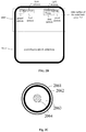
- Fig.1 which illustrates a back view of a three-piece terminal housing
- the metal housing is divided into three parts, and "blank band" gaps exist between the three parts as signal outlets, such that the antennas may transmit or receive signals via the signal outlets.
- the metal housing with the "blank band” gaps is not a truly all-metal housing, which affects the aesthetic appearance of the terminal. Therefore, we have appreciated that how to design the antennas to enable a terminal to have a truly all-metal housing is a problem to be solved.
- a terminal housing may include: a metal back cover, a nonconductive material overlaid on an outer surface of the metal back cover, a plurality of antenna units arranged on the nonconductive material, and a printed circuit board (PCB) arranged on the inner surface of the metal back cover, the metal back cover includes an opening thereon; wherein each of the plurality of antenna units includes a ground portion and a feed portion; the ground portion of each of the antenna units passes through the nonconductive material and is connected with the outer surface of the metal back cover, and the feed portion of each of the antenna units is connected with a radio frequency (RF) front-end of the PCB via a shield wire, the shield wire passes through the nonconductive material and enters into the terminal housing via the opening on the metal back cover.
- RF radio frequency
- each of the antenna units is fixedly connected with the outer surface of the metal back cover; or the ground portion of each of the antenna units is connected with the outer surface of the metal back cover by surface contact.
- connection by surface contact is a connection by a flexure strip.
- thickness of the nonconductive material is more than a designated threshold, so as to ensure radiation performance of the plurality of antenna units.
- the shield wire is a coaxial wire, which includes, from inside out, a plastic protective layer, a metal shield layer, a metal probe and a nonconductive medium layer.
- the PCB is a strip line, which includes a top ground layer, a bottom ground layer, and an intermediate layer which is used for transmitting signals; and the shield wire is connected with the intermediate layer of the RF front-end.
- the RF front-end is stair-step shaped, so as to ensure impedance matching between the shield wire and the RF front-end.
- the metal back cover, the nonconductive material and the plurality of antenna units are sprayed with the same color.
- the entire outer surface of the metal back cover is overlaid with the nonconductive material; or a part of the outer surface of the metal back cover is overlaid with the nonconductive material, the part of the outer surface corresponds to positions of the plurality of antenna units.
- the plurality of antenna units is embedded into the nonconductive material, and upper surfaces of the plurality of antenna units are aligned with the upper surface of the nonconductive material.
- thicknesses of the plurality of antenna units are less than thickness of the nonconductive material.
- the plurality of antenna units are arranged on top or bottom of the outer surface of the metal back cover.
- the plurality of antenna units are all planar inverted-F antennas (PIFA).
- the plurality of antenna units includes at least a Wireless Fidelity (WiFi) antenna, a global positioning system (GPS) antenna and a communication antenna.
- WiFi Wireless Fidelity
- GPS global positioning system
- a terminal is provided.
- the terminal includes the terminal housing described in the first aspect.
- Embodiments of the present disclosure may provide at least some of the following beneficial effects.
- the ground portions of the antenna units are connected with the metal back cover and the feed portions of the antenna units are connected with the RF front-end, such that the antenna units and the RF front-end may constitute a receiving path or a transmitting path; and due to the antenna units being arranged outside the terminal housing, the receiving and transmitting of signals by the antenna units would not be affected when the terminal housing is all-metal, therefore, the purpose of designing a all-metal housing as the terminal housing may be achieved.
- Fig. 2A and Fig. 2B are structural schematic diagrams illustrating a terminal housing according to an exemplary embodiment.
- Fig. 2B is a back view, viewed from the back of the terminal.
- the terminal includes a terminal housing.
- the terminal housing includes a metal back cover 201, a nonconductive material 202 overlaid on an outer surface of the metal back cover 201, a plurality of antenna units 203 arranged on the nonconductive material 202 and a PCB 204 arranged on the inner surface of the metal back cover 201, the metal back cover 201 includes an opening 205 thereon.
- Each of the plurality of antenna units 203 may include a ground portion 2031 and a feed portion 2032.
- the ground portion 2031 of each of the antenna units passes through the nonconductive material 202 and is connected with the outer surface of the metal back cover 201; the feed portion 2032 of each of the antenna units is connected with a radio frequency (RF) front-end 2041 of the PCB 204 via a shield wire 206, such that the antenna unit and the RF front-end 2041 may constitute a receiving path or a transmitting path to achieve the normal operation of each antenna unit.
- the shield wire 206 passes through the nonconductive material 202 and enters into the terminal housing via the opening 205 on the metal back cover 201, so as to connect to the RF front-end 2041.
- Thickness d of the nonconductive material 201 is required to be more than a designated threshold so as to ensure the radiation performance of multiple antenna units.
- the designated threshold may be preset by designers.
- PCB 204 is disposed on the inner surface of the metal back cover 201, inside the terminal housing and is not adhered by adhesive with the metal back cover.
- the PCB 204 is a strip line, which includes three layers: a top layer, a bottom layer, and an intermediate layer, wherein the top layer and the bottom layer are ground layers, and the intermediate layer is a signal layer for transmitting signals.
- the shield wire 206 is connected with the intermediate layer of the RF front-end 2041.
- the RF front-end of the PCB 204 may be designed as stair-step shape, so as to ensure impedance matching between the shield wire 206 and the RF front-end 2041.
- the specific size of the stair-step shape may be adjusted by designers based on the radiation performance of the antenna unit, which is not concretely limited by embodiments of the present disclosure.
- each of the antenna units may be connected with the outer surface of the metal back cover 201 in the following two ways.
- each of the antenna units is fixedly connected with the outer surface of the metal back cover 201.
- Fixing bolts or other conductive objects may be employed to fixedly connect them, which is not concretely limited by embodiments of the present disclosure.
- the ground portion of each of the antenna units is connected with the outer surface of the metal back cover 201 by surface contact, that is, the ground portion of each of the antenna units is not welded together with the outer surface of the metal back cover.
- the connection by surface contact may be achieved by a flexure strip or by other conductive objects by way of surface contact, which is not concretely limited by embodiments of the present disclosure.
- the flexure strip is a conductive object.
- the conductive objects employed in the above two connections ways may be considered as a part of the ground portion.
- the shield wire 206 is used for transmitting communication signals and shielding interference of the metal back cover 201 on the communication signal, so as to ensure the radiation performance of the antennas.
- the shield wire 206 may be a coaxial wire, which includes, from inside out, a plastic protective layer 2061, a metal shield layer 2062, a metal probe 2063 and a nonconductive medium layer 2064, as shown in Fig. 2C which is a cross-sectional diagram illustrating a coaxial wire.
- the shield wire 206 may be other connection wires which may shield interference of the metal back cover on the communication signal, which is not concretely limited by embodiments of the present disclosure.
- the nonconductive material may be plastic, glass, rubber, etc., which is not concretely limited by embodiments of the present disclosure.
- the shape and diameter of the opening 205 may be preset based on the diameter and the cross-sectional shape of the shield wire, which is not concretely limited by embodiments of the present disclosure.
- the plurality of antenna units 203 are all planar inverted-F antennas (PIFA).
- the plurality of antenna units 203 may be arranged on the top or bottom of the outer surface of the metal back cover, as shown in Fig. 2B .
- the plurality of antenna units 203 may include at least a WiFi antenna, a GPS antenna and a communication antenna.
- the communication antenna may further include a high frequency communication antenna and a low frequency communication antenna, for example, GSM (Global System for Mobile Communication) antenna, CDMA (Code Division Multiple Access) antenna, TD-SCDMA (Time Division-Synchronous Code Division Multiple) antenna, LTE (Long Term Evolution) antenna and the like, which is not concretely limited by embodiments of the present disclosure.
- GSM Global System for Mobile Communication
- CDMA Code Division Multiple Access
- TD-SCDMA Time Division-Synchronous Code Division Multiple
- LTE Long Term Evolution
- the WiFi antenna and the GPS antenna all include the ground portion and the feed portion.
- the distances between the antenna units and the top or the bottom of the outer surface of the metal back cover 201 may be preset by designers.
- the metal back cover, the nonconductive material and the plurality of antenna units are sprayed with the same color so as to ensure aesthetics of the terminal, the color may be gold, silver, black, rose gold, pink, white and the like, which is not concretely limited by embodiments of the present disclosure.
- the relationship between the metal back cover and the nonconductive material may be one of the two following relationships.
- the entire outer surface of the metal back cover 201 is overlaid with the nonconductive material 202.
- a part of the outer surface of the metal back cover 201 is overlaid with the nonconductive material 202, wherein the part of the outer surface corresponds to positions of the plurality of antenna units, that is, the nonconductive material 202 merely exist on the area of the metal back cover 201 overlapping with the plurality of the antenna units 203.
- the plurality of antenna units 203 may be embedded into the nonconductive material 202 and the upper surfaces of the plurality of antenna units 203 are aligned with the upper surface of the nonconductive material 202, as shown in Fig. 2D , which is a schematic diagram illustrating an antenna unit being embedded into a nonconductive material.
- the antenna units when the antenna units are embedded into the nonconductive material, it is required to ensure that the thickness of the plurality of antenna units is less than the thickness of the nonconductive material, so as to avoid the antenna units from contacting the metal back cover which leads to abnormal operations of the antenna units.
- the antenna units are disposed on the inner surface of the metal back cover (i.e., inside the terminal housing), a certain area of clearance region inside the terminal housing should be reserved for the antenna units so as to ensure that there is no influence on the antennas by other circuits, and ensure the normal operation of the antenna units. Besides, there is no any element in the clearance region.
- the antenna units are disposed outside the metal back cover, so the antenna units may work normally without reserving the clearance region inside the terminal housing, which can save the inner space of the terminal housing, improve the utilization of the inner space of the terminal housing and also reduce the size of the terminal.
- the nonconductive material 202 is casted on the lower surface of the plurality of antenna units 203 firstly, and then the nonconductive material 202 and the plurality of antenna units 203 are fixed on the outer surface of the metal back cover 201; alternatively, the nonconductive material 202 is fixed on the outer surface of the metal back cover 201 firstly, and then the antenna units are arranged on the nonconductive material, which is not concretely limited by embodiments of the present disclosure.
- Fig. 3 is a Return Loss (RL) curve of a WiFi antenna according to an exemplary embodiment.
- the WiFi antenna is disposed on the top of the outer surface of the metal back cover 201, as shown in Fig. 2B .
- the distance between the top of the WiFi antenna and the top of the metal back cover is 5mm.
- the WiFi antenna may be operated at the frequency band of 2.4G.
- the RL of the WiFi antenna is less than -5dB nearby the frequency of 2.4GHz, the least RL may reach -20dB, which meets the design requirement.
- Fig. 4 is a RL curve of a GPS antenna according to an exemplary embodiment.
- the GPS antenna is disposed on the top of the outer surface of the metal back cover 201, as shown in Fig. 2B .
- the distance between the top of the WiFi antenna and the top of the metal back cover is 5mm.
- the WiFi antenna may receive the communication signals form L1 wave band which corresponds to the frequency of 1575.42MHz.
- the RL of the WiFi antenna is less than -5dB nearby the frequency of 1575.42MHz, the least RL may reach -5dB, which meets the design requirement.
- a terminal housing is provided in an embodiment of the present disclosure.
- the ground portions of the antenna units are connected with the metal back cover, and the feed portions of the antenna units are connected with the RF front-end of a PCB, such that the antenna units and the RF front-end may constitute a receiving path or a transmitting path; and due to the antenna units being arranged outside the terminal housing, the receiving and transmitting of signals by the antenna units is not affected when the terminal housing is all-metal, therefore, the purpose of designing an all-metal terminal housing may be achieved. Furthermore, arranging the antenna units outside the terminal housing may save the inner space of the terminal housing.
- the terminal includes the terminal housing described in the above embodiments and all the structures and functions of the terminal housing, which will not be repeated herein.
- the terminal further includes a terminal front housing, a terminal display and other electronic components in the terminal.
- the plurality of antenna units included in the terminal housing are in cooperation with the other components in the terminal to achieve the communication function of the terminal, components of the terminal are not limited concretely by the present disclosure.
Landscapes
- Engineering & Computer Science (AREA)
- Signal Processing (AREA)
- Computer Networks & Wireless Communication (AREA)
- Physics & Mathematics (AREA)
- Electromagnetism (AREA)
- Support Of Aerials (AREA)
- Telephone Set Structure (AREA)
Abstract
Description
- The present disclosure relates to a technical field of terminal, and more particularly, to a terminal housing and a terminal including the terminal housing.
- With the development of science and technology, there is a trend to design a metal housing as the housing for a terminal. When designing a metal housing for a terminal, it may be usually designed to have a three-piece structure such that the metal housing would not affect terminal antennas transmitting and receiving signals normally. As shown in
Fig.1 , which illustrates a back view of a three-piece terminal housing, the metal housing is divided into three parts, and "blank band" gaps exist between the three parts as signal outlets, such that the antennas may transmit or receive signals via the signal outlets. However, the metal housing with the "blank band" gaps is not a truly all-metal housing, which affects the aesthetic appearance of the terminal. Therefore, we have appreciated that how to design the antennas to enable a terminal to have a truly all-metal housing is a problem to be solved. - In view of the fact in related arts, a terminal housing and a terminal are provided by the present disclosure. The technical solutions are set forth as follows.
- According to a first aspect of embodiments of the present disclosure, a terminal housing is provided. The terminal housing may include: a metal back cover, a nonconductive material overlaid on an outer surface of the metal back cover, a plurality of antenna units arranged on the nonconductive material, and a printed circuit board (PCB) arranged on the inner surface of the metal back cover, the metal back cover includes an opening thereon; wherein each of the plurality of antenna units includes a ground portion and a feed portion; the ground portion of each of the antenna units passes through the nonconductive material and is connected with the outer surface of the metal back cover, and the feed portion of each of the antenna units is connected with a radio frequency (RF) front-end of the PCB via a shield wire, the shield wire passes through the nonconductive material and enters into the terminal housing via the opening on the metal back cover.
- Alternatively, the ground portion of each of the antenna units is fixedly connected with the outer surface of the metal back cover; or the ground portion of each of the antenna units is connected with the outer surface of the metal back cover by surface contact.
- Alternatively, the connection by surface contact is a connection by a flexure strip.
- Alternatively, thickness of the nonconductive material is more than a designated threshold, so as to ensure radiation performance of the plurality of antenna units.
- Alternatively, the shield wire is a coaxial wire, which includes, from inside out, a plastic protective layer, a metal shield layer, a metal probe and a nonconductive medium layer.
- Alternatively, the PCB is a strip line, which includes a top ground layer, a bottom ground layer, and an intermediate layer which is used for transmitting signals; and the shield wire is connected with the intermediate layer of the RF front-end.
- Alternatively, the RF front-end is stair-step shaped, so as to ensure impedance matching between the shield wire and the RF front-end.
- Alternatively, the metal back cover, the nonconductive material and the plurality of antenna units are sprayed with the same color.
- Alternatively, the entire outer surface of the metal back cover is overlaid with the nonconductive material; or a part of the outer surface of the metal back cover is overlaid with the nonconductive material, the part of the outer surface corresponds to positions of the plurality of antenna units.
- Alternatively, the plurality of antenna units is embedded into the nonconductive material, and upper surfaces of the plurality of antenna units are aligned with the upper surface of the nonconductive material.
- Alternatively, thicknesses of the plurality of antenna units are less than thickness of the nonconductive material.
- Alternatively, the plurality of antenna units are arranged on top or bottom of the outer surface of the metal back cover.
- Alternatively, the plurality of antenna units are all planar inverted-F antennas (PIFA).
- Alternatively, the plurality of antenna units includes at least a Wireless Fidelity (WiFi) antenna, a global positioning system (GPS) antenna and a communication antenna.
- According to a second aspect of embodiments of the present disclosure, a terminal is provided. The terminal includes the terminal housing described in the first aspect.
- Embodiments of the present disclosure may provide at least some of the following beneficial effects.
- The ground portions of the antenna units are connected with the metal back cover and the feed portions of the antenna units are connected with the RF front-end, such that the antenna units and the RF front-end may constitute a receiving path or a transmitting path; and due to the antenna units being arranged outside the terminal housing, the receiving and transmitting of signals by the antenna units would not be affected when the terminal housing is all-metal, therefore, the purpose of designing a all-metal housing as the terminal housing may be achieved.
- It is to be understood that the above general description and the following detailed description are merely for the purpose of illustration and explanation, and are not intended to limit the scope of the protection of the disclosure.
- The accompanying drawings, which are incorporated in and constitute a part of this specification, illustrate embodiments consistent with the disclosure and, together with the description, serve to explain the principles of the disclosure.
-
Fig. 1 is a back view of a three-piece terminal housing in the related technologies. -
Fig. 2A is a structural schematic diagram illustrating a terminal housing according to an exemplary embodiment. -
Fig. 2B is a structural schematic diagram illustrating a terminal housing according to an exemplary embodiment. -
Fig. 2C is a cross-sectional diagram illustrating a coaxial wire according to an exemplary embodiment. -
Fig. 2D is a schematic diagram illustrating an antenna unit being embedded into a nonconductive material according to an exemplary embodiment. -
Fig. 3 is a Return Loss (RL) curve of a WiFi antenna according to an exemplary embodiment. -
Fig. 4 is a RL curve of a GPS antenna according to an exemplary embodiment. - In order to make the purpose, the technical solution and advantages of the present disclosure more clear, reference will now be made in detail to exemplary embodiments in junction with the accompanying drawings.
- Reference will now be made in detail to example embodiments, examples of which are illustrated in the accompanying drawings. The following description refers to the accompanying drawings in which same numbers in different drawings represent same or similar elements unless otherwise described. The implementations set forth in the following description of example embodiments do not represent all implementations consistent with the present disclosure. Instead, they are merely examples of devices and methods consistent with aspects related to the present disclosure as recited in the appended claims.
-
Fig. 2A andFig. 2B are structural schematic diagrams illustrating a terminal housing according to an exemplary embodiment.Fig. 2B is a back view, viewed from the back of the terminal. The terminal includes a terminal housing. The terminal housing includes ametal back cover 201, anonconductive material 202 overlaid on an outer surface of themetal back cover 201, a plurality ofantenna units 203 arranged on thenonconductive material 202 and aPCB 204 arranged on the inner surface of themetal back cover 201, themetal back cover 201 includes an opening 205 thereon. - It should be noted that, for the purpose of illustrating the relationship of the antenna unit, nonconductive material and the metal back cover, only one antenna unit is shown in
Fig.2A . - Each of the plurality of
antenna units 203 may include aground portion 2031 and afeed portion 2032. Theground portion 2031 of each of the antenna units passes through thenonconductive material 202 and is connected with the outer surface of themetal back cover 201; thefeed portion 2032 of each of the antenna units is connected with a radio frequency (RF) front-end 2041 of thePCB 204 via ashield wire 206, such that the antenna unit and the RF front-end 2041 may constitute a receiving path or a transmitting path to achieve the normal operation of each antenna unit. Theshield wire 206 passes through thenonconductive material 202 and enters into the terminal housing via the opening 205 on themetal back cover 201, so as to connect to the RF front-end 2041. Thickness d of thenonconductive material 201 is required to be more than a designated threshold so as to ensure the radiation performance of multiple antenna units. The designated threshold may be preset by designers. - In embodiments of the present disclosure, PCB 204 is disposed on the inner surface of the
metal back cover 201, inside the terminal housing and is not adhered by adhesive with the metal back cover. ThePCB 204 is a strip line, which includes three layers: a top layer, a bottom layer, and an intermediate layer, wherein the top layer and the bottom layer are ground layers, and the intermediate layer is a signal layer for transmitting signals. Theshield wire 206 is connected with the intermediate layer of the RF front-end 2041. - It should be noted that the RF front-end of the
PCB 204 may be designed as stair-step shape, so as to ensure impedance matching between theshield wire 206 and the RF front-end 2041. The specific size of the stair-step shape may be adjusted by designers based on the radiation performance of the antenna unit, which is not concretely limited by embodiments of the present disclosure. - The ground portion of each of the antenna units may be connected with the outer surface of the metal back
cover 201 in the following two ways. - In the first connection way, the ground portion of each of the antenna units is fixedly connected with the outer surface of the metal back
cover 201. Fixing bolts or other conductive objects may be employed to fixedly connect them, which is not concretely limited by embodiments of the present disclosure. - In the second connection way, the ground portion of each of the antenna units is connected with the outer surface of the metal back
cover 201 by surface contact, that is, the ground portion of each of the antenna units is not welded together with the outer surface of the metal back cover. The connection by surface contact may be achieved by a flexure strip or by other conductive objects by way of surface contact, which is not concretely limited by embodiments of the present disclosure. The flexure strip is a conductive object. - The conductive objects employed in the above two connections ways may be considered as a part of the ground portion.
- The
shield wire 206 is used for transmitting communication signals and shielding interference of the metal backcover 201 on the communication signal, so as to ensure the radiation performance of the antennas. Theshield wire 206 may be a coaxial wire, which includes, from inside out, a plasticprotective layer 2061, a metal shield layer 2062, ametal probe 2063 and anonconductive medium layer 2064, as shown inFig. 2C which is a cross-sectional diagram illustrating a coaxial wire. In addition to the coaxial wire, theshield wire 206 may be other connection wires which may shield interference of the metal back cover on the communication signal, which is not concretely limited by embodiments of the present disclosure. - The nonconductive material may be plastic, glass, rubber, etc., which is not concretely limited by embodiments of the present disclosure. The shape and diameter of the
opening 205 may be preset based on the diameter and the cross-sectional shape of the shield wire, which is not concretely limited by embodiments of the present disclosure. - It should be noted that the plurality of
antenna units 203 are all planar inverted-F antennas (PIFA). The plurality ofantenna units 203 may be arranged on the top or bottom of the outer surface of the metal back cover, as shown inFig. 2B . The plurality ofantenna units 203 may include at least a WiFi antenna, a GPS antenna and a communication antenna. The communication antenna may further include a high frequency communication antenna and a low frequency communication antenna, for example, GSM (Global System for Mobile Communication) antenna, CDMA (Code Division Multiple Access) antenna, TD-SCDMA (Time Division-Synchronous Code Division Multiple) antenna, LTE (Long Term Evolution) antenna and the like, which is not concretely limited by embodiments of the present disclosure.Fig. 2B merely illustrates a WiFi antenna and a GPS antenna disposed on the top of the metal backcover 201 and a communication antenna disposed on the bottom of the metal back cover. The specific position of each of the antenna units is not limited by embodiments of the present disclosure. The WiFi antenna and the GPS antenna all include the ground portion and the feed portion. - The distances between the antenna units and the top or the bottom of the outer surface of the metal back
cover 201 may be preset by designers. - It should be noted that the metal back cover, the nonconductive material and the plurality of antenna units are sprayed with the same color so as to ensure aesthetics of the terminal, the color may be gold, silver, black, rose gold, pink, white and the like, which is not concretely limited by embodiments of the present disclosure.
- In order to improve the flexibility and diversity of the design, the relationship between the metal back cover and the nonconductive material may be one of the two following relationships.
- In the first relationship, the entire outer surface of the metal back
cover 201 is overlaid with thenonconductive material 202. - In the second relationship, a part of the outer surface of the metal back
cover 201 is overlaid with thenonconductive material 202, wherein the part of the outer surface corresponds to positions of the plurality of antenna units, that is, thenonconductive material 202 merely exist on the area of the metal backcover 201 overlapping with the plurality of theantenna units 203. - For the purpose of reducing the total thickness of the
nonconductive material 202 and the plurality of theantenna units 203 so as to reduce the thickness of the terminal and improve the aesthetics of the terminal, the plurality ofantenna units 203 may be embedded into thenonconductive material 202 and the upper surfaces of the plurality ofantenna units 203 are aligned with the upper surface of thenonconductive material 202, as shown inFig. 2D , which is a schematic diagram illustrating an antenna unit being embedded into a nonconductive material. - It should be noted that, when the antenna units are embedded into the nonconductive material, it is required to ensure that the thickness of the plurality of antenna units is less than the thickness of the nonconductive material, so as to avoid the antenna units from contacting the metal back cover which leads to abnormal operations of the antenna units.
- It should be noted that, in general cases, when the antenna units are disposed on the inner surface of the metal back cover (i.e., inside the terminal housing), a certain area of clearance region inside the terminal housing should be reserved for the antenna units so as to ensure that there is no influence on the antennas by other circuits, and ensure the normal operation of the antenna units. Besides, there is no any element in the clearance region. However, in embodiments of the present disclosure, the antenna units are disposed outside the metal back cover, so the antenna units may work normally without reserving the clearance region inside the terminal housing, which can save the inner space of the terminal housing, improve the utilization of the inner space of the terminal housing and also reduce the size of the terminal.
- It should be noted that, in a specific embodiment, the
nonconductive material 202 is casted on the lower surface of the plurality ofantenna units 203 firstly, and then thenonconductive material 202 and the plurality ofantenna units 203 are fixed on the outer surface of the metal backcover 201; alternatively, thenonconductive material 202 is fixed on the outer surface of the metal backcover 201 firstly, and then the antenna units are arranged on the nonconductive material, which is not concretely limited by embodiments of the present disclosure. -
Fig. 3 is a Return Loss (RL) curve of a WiFi antenna according to an exemplary embodiment. The WiFi antenna is disposed on the top of the outer surface of the metal backcover 201, as shown inFig. 2B . The distance between the top of the WiFi antenna and the top of the metal back cover is 5mm. The WiFi antenna may be operated at the frequency band of 2.4G. As shown inFig. 3 , the RL of the WiFi antenna is less than -5dB nearby the frequency of 2.4GHz, the least RL may reach -20dB, which meets the design requirement. -
Fig. 4 is a RL curve of a GPS antenna according to an exemplary embodiment. The GPS antenna is disposed on the top of the outer surface of the metal backcover 201, as shown inFig. 2B . The distance between the top of the WiFi antenna and the top of the metal back cover is 5mm. The WiFi antenna may receive the communication signals form L1 wave band which corresponds to the frequency of 1575.42MHz. As shown inFig. 3 , the RL of the WiFi antenna is less than -5dB nearby the frequency of 1575.42MHz, the least RL may reach -5dB, which meets the design requirement. - A terminal housing is provided in an embodiment of the present disclosure. the ground portions of the antenna units are connected with the metal back cover, and the feed portions of the antenna units are connected with the RF front-end of a PCB, such that the antenna units and the RF front-end may constitute a receiving path or a transmitting path; and due to the antenna units being arranged outside the terminal housing, the receiving and transmitting of signals by the antenna units is not affected when the terminal housing is all-metal, therefore, the purpose of designing an all-metal terminal housing may be achieved. Furthermore, arranging the antenna units outside the terminal housing may save the inner space of the terminal housing.
- A terminal is also provided according to an embodiment of the present disclosure, the terminal includes the terminal housing described in the above embodiments and all the structures and functions of the terminal housing, which will not be repeated herein. Notably, the terminal further includes a terminal front housing, a terminal display and other electronic components in the terminal. The plurality of antenna units included in the terminal housing are in cooperation with the other components in the terminal to achieve the communication function of the terminal, components of the terminal are not limited concretely by the present disclosure.
- Other embodiments of the invention will be apparent to those skilled in the art from consideration of the specification and practice of the disclosures herein. This application is intended to cover any variations, uses, or adaptations of the disclosure following the general principles thereof and including such departures from the present disclosure as come within known or customary practice in the art. It is intended that the specification and examples be considered as exemplary only, with a true scope of the invention being defined by the following claims.
- It will be appreciated that the disclosure is not limited to the exact construction that has been described above and illustrated in the accompanying drawings, and that various modifications and changes can be made without departing from the scope thereof. It is intended that the scope of the invention only be limited by the appended claims.
Claims (15)
- A terminal housing, characterized by comprising: a metal back cover (201), a nonconductive material (202) overlaid on an outer surface of the metal back cover (201), a plurality of antenna units (203) arranged on the nonconductive material (202), and a printed circuit board (PCB) (204) arranged on the inner surface of the metal back cover (201), the metal back cover (201) including an opening (205) therein; wherein
each of the plurality of antenna units (203) includes a ground portion (2031) and a feed portion (2032);
the ground portion (2031) of each of the antenna units (203) passes through the nonconductive material (202) and is connected with the outer surface of the metal back cover (201), and
the feed portion (2032) of each of the antenna units (203) is connected with a radio frequency (RF) front-end (2041) of the PCB (204) via a shield wire (206), wherein the shield wire ( 206) passes through the nonconductive material (202) and enters into the terminal housing via the opening ( 205) on the metal back cover (201). - The terminal housing of claim 1, wherein the ground portion (2031) of each of the antenna units (203) is fixedly connected with the outer surface of the metal back cover (201); or the ground portion (2031) of each of the antenna units (203) is connected with the outer surface of the metal back cover (201) by surface contact.
- The terminal housing of claim 2, wherein the connection by surface contact is a connection by a flexure strip.
- The terminal housing of claim 1, wherein the thickness of the nonconductive material (202) is more than a designated threshold, so as to ensure radiation performance of the plurality of antenna units (203).
- The terminal housing of claim 1, wherein the shield wire (206) is a coaxial wire, which includes, from inside out, a plastic protective layer (2061), a metal shield layer (2062), a metal probe (2063) and a nonconductive medium layer (2064).
- The terminal housing of claim 1, wherein the PCB (204) is a strip line, which includes a top ground layer, a bottom ground layer, and an intermediate layer which is used for transmitting signals; and
the shield wire (206) is connected with the intermediate layer of the RF front-end (2041). - The terminal housing of claim 1 or 6, wherein the RF front-end (2041) is stair-step shaped, so as to ensure impedance matching between the shield wire (206) and the RF front-end (2041).
- The terminal housing of claim 1, wherein the metal back cover (201), the nonconductive material (202) and the plurality of antenna units (203) are sprayed with the same color.
- The terminal housing of claim 1, wherein the entire outer surface of the metal back cover (201) is overlaid with the nonconductive material (202); or a part of the outer surface of the metal back cover (201) is overlaid with the nonconductive material (202), the part of the outer surface corresponds to positions of the plurality of antenna units (203).
- The terminal housing of claim 1, wherein the plurality of antenna units (203) is embedded into the nonconductive material (202), and upper surfaces of the plurality of antenna units (203) are aligned with the upper surface of the nonconductive material (202).
- The terminal housing of claim 9, wherein the thickness of the plurality of antenna units (203) is less than the thickness of the nonconductive material (202).
- The terminal housing of claim 1, wherein the plurality of antenna units (203) are arranged on top or bottom of the outer surface of the metal back cover (201).
- The terminal housing of claim 1, wherein the plurality of antenna units (203) are all planar inverted-F antennas (PIFA).
- The terminal housing of claim 1, wherein the plurality of antenna units (203) include at least a Wireless Fidelity (WiFi) antenna, a global positioning system (GPS) antenna and a communication antenna.
- A terminal, characterized by comprising the terminal housing of any one of claim 1 to 14.
Applications Claiming Priority (1)
| Application Number | Priority Date | Filing Date | Title |
|---|---|---|---|
| CN201610326989.4A CN107395788B (en) | 2016-05-17 | 2016-05-17 | Terminal shell and terminal |
Publications (1)
| Publication Number | Publication Date |
|---|---|
| EP3246990A1 true EP3246990A1 (en) | 2017-11-22 |
Family
ID=58701421
Family Applications (1)
| Application Number | Title | Priority Date | Filing Date |
|---|---|---|---|
| EP17169711.3A Ceased EP3246990A1 (en) | 2016-05-17 | 2017-05-05 | Terminal housing and terminal |
Country Status (4)
| Country | Link |
|---|---|
| US (1) | US10461404B2 (en) |
| EP (1) | EP3246990A1 (en) |
| CN (1) | CN107395788B (en) |
| WO (1) | WO2017197795A1 (en) |
Cited By (5)
| Publication number | Priority date | Publication date | Assignee | Title |
|---|---|---|---|---|
| CN108737601A (en) * | 2018-05-11 | 2018-11-02 | Oppo广东移动通信有限公司 | Shell, electronic device and method for producing shell |
| CN108769308A (en) * | 2018-05-25 | 2018-11-06 | Oppo广东移动通信有限公司 | shell and electronic device |
| CN112153833A (en) * | 2019-06-28 | 2020-12-29 | Oppo广东移动通信有限公司 | Shell assembly, antenna device and electronic equipment |
| DE102019211547A1 (en) * | 2019-08-01 | 2021-02-04 | Robert Bosch Gmbh | Control unit with antenna |
| WO2021076625A1 (en) * | 2019-10-14 | 2021-04-22 | Google Llc | Millimeter wave radar on flexible printed circuit board |
Families Citing this family (9)
| Publication number | Priority date | Publication date | Assignee | Title |
|---|---|---|---|---|
| ES2717107T3 (en) * | 2016-08-25 | 2019-06-19 | Guangdong Oppo Mobile Telecommunications Corp Ltd | Mobile terminal, housing component and manufacturing method thereof |
| ES2715974T3 (en) * | 2016-08-25 | 2019-06-07 | Guangdong Oppo Mobile Telecommunications Corp Ltd | Mobile terminal, housing component and manufacturing method |
| TWI644479B (en) * | 2017-01-05 | 2018-12-11 | 和碩聯合科技股份有限公司 | Multiple antenna apparatus |
| CN109935959A (en) * | 2017-12-18 | 2019-06-25 | 比亚迪股份有限公司 | Communication equipment and its glass rear shell |
| CN110400779B (en) * | 2018-04-25 | 2022-01-11 | 华为技术有限公司 | Packaging structure |
| KR102526400B1 (en) | 2018-09-06 | 2023-04-28 | 삼성전자주식회사 | An electronic device comprising a 5g antenna module |
| CN111786096B (en) * | 2019-04-03 | 2023-02-21 | 北京小米移动软件有限公司 | Antenna and electronic equipment |
| CN112234362B (en) * | 2019-06-30 | 2022-03-01 | Oppo广东移动通信有限公司 | Shell assembly, antenna assembly and electronic equipment |
| KR20220068030A (en) * | 2020-11-18 | 2022-05-25 | 삼성전자주식회사 | A printed circuit board structure and electronic device inclduing same |
Citations (6)
| Publication number | Priority date | Publication date | Assignee | Title |
|---|---|---|---|---|
| US5121127A (en) * | 1988-09-30 | 1992-06-09 | Sony Corporation | Microstrip antenna |
| JP2001267833A (en) * | 2000-03-16 | 2001-09-28 | Mitsubishi Electric Corp | Microstrip antenna |
| FR2823601A1 (en) * | 2001-04-13 | 2002-10-18 | Socapex Amphenol | Mobile phone patch antenna behind casing uses air dielectric reduces cost and mass |
| WO2011018551A1 (en) * | 2009-08-14 | 2011-02-17 | Perlos Oyj | Electronic device |
| EP2387102A2 (en) * | 2010-05-11 | 2011-11-16 | Sony Ericsson Mobile Communications AB | Antenna array with capacitive coupled upper and lower antenna elements and a peak radiation pattern directed toward the lower antenna element |
| US20140300518A1 (en) * | 2011-02-11 | 2014-10-09 | Pulse Finland Oy | Chassis-excited antenna apparatus and methods |
Family Cites Families (23)
| Publication number | Priority date | Publication date | Assignee | Title |
|---|---|---|---|---|
| US3643007A (en) * | 1969-04-02 | 1972-02-15 | Superior Continental Corp | Coaxial cable |
| JPH088445B2 (en) * | 1987-10-16 | 1996-01-29 | 日立化成工業株式会社 | Microstrip antenna structure |
| AT393054B (en) * | 1989-07-27 | 1991-08-12 | Siemens Ag Oesterreich | TRANSMITTER AND / OR RECEIVING ARRANGEMENT FOR PORTABLE DEVICES |
| US6346913B1 (en) * | 2000-02-29 | 2002-02-12 | Lucent Technologies Inc. | Patch antenna with embedded impedance transformer and methods for making same |
| US6731920B1 (en) * | 2000-03-31 | 2004-05-04 | Matsushita Electric Industrial Co., Ltd. | Portable telephone apparatus and control method thereof |
| US6531985B1 (en) * | 2000-08-14 | 2003-03-11 | 3Com Corporation | Integrated laptop antenna using two or more antennas |
| GB2392563B (en) * | 2002-08-30 | 2004-11-03 | Motorola Inc | Antenna structures and their use in wireless communication devices |
| WO2007014737A2 (en) * | 2005-08-01 | 2007-02-08 | Fractus, S.A. | Antenna with inner spring contact |
| JP4102411B2 (en) | 2006-04-13 | 2008-06-18 | 株式会社東芝 | Mobile communication terminal |
| US7876274B2 (en) * | 2007-06-21 | 2011-01-25 | Apple Inc. | Wireless handheld electronic device |
| CN201247808Y (en) * | 2008-08-11 | 2009-05-27 | 耀登科技股份有限公司 | Antenna structure of metal case mobile phone |
| CN101728630B (en) * | 2009-12-21 | 2013-07-10 | 瑞声声学科技(深圳)有限公司 | Electronic communication equipment and manufacturing process thereof |
| JP4960515B1 (en) * | 2011-03-18 | 2012-06-27 | 株式会社東芝 | Electronics |
| US9153856B2 (en) | 2011-09-23 | 2015-10-06 | Apple Inc. | Embedded antenna structures |
| EP2709205A1 (en) * | 2012-09-13 | 2014-03-19 | LG Innotek Co., Ltd. | Antenna apparatus and method of manufacturing the same |
| CN103327144A (en) * | 2013-05-22 | 2013-09-25 | 华为终端有限公司 | Mobile terminal |
| CN103401059B (en) * | 2013-07-29 | 2015-08-26 | 广东欧珀移动通信有限公司 | Antenna device for full metal shell |
| WO2016063759A1 (en) | 2014-10-20 | 2016-04-28 | 株式会社村田製作所 | Wireless communication module |
| CN204441445U (en) | 2015-04-03 | 2015-07-01 | 京东方科技集团股份有限公司 | Mobile display terminal |
| CN204632895U (en) * | 2015-04-07 | 2015-09-09 | 龚永祥 | A kind of feeder radio frequency coaxial-cable |
| CN204809404U (en) * | 2015-06-23 | 2015-11-25 | 联想(北京)有限公司 | Mobile terminal antenna and mobile terminal |
| CN104993216A (en) * | 2015-07-17 | 2015-10-21 | 苏州纳安特通信科技有限公司 | NFC antenna structure for metal back cover mobile phone |
| CN105024136A (en) * | 2015-07-31 | 2015-11-04 | 瑞声声学科技(苏州)有限公司 | Mobile terminal |
-
2016
- 2016-05-17 CN CN201610326989.4A patent/CN107395788B/en active Active
- 2016-08-11 WO PCT/CN2016/094702 patent/WO2017197795A1/en active Application Filing
-
2017
- 2017-05-05 EP EP17169711.3A patent/EP3246990A1/en not_active Ceased
- 2017-05-16 US US15/597,121 patent/US10461404B2/en active Active
Patent Citations (6)
| Publication number | Priority date | Publication date | Assignee | Title |
|---|---|---|---|---|
| US5121127A (en) * | 1988-09-30 | 1992-06-09 | Sony Corporation | Microstrip antenna |
| JP2001267833A (en) * | 2000-03-16 | 2001-09-28 | Mitsubishi Electric Corp | Microstrip antenna |
| FR2823601A1 (en) * | 2001-04-13 | 2002-10-18 | Socapex Amphenol | Mobile phone patch antenna behind casing uses air dielectric reduces cost and mass |
| WO2011018551A1 (en) * | 2009-08-14 | 2011-02-17 | Perlos Oyj | Electronic device |
| EP2387102A2 (en) * | 2010-05-11 | 2011-11-16 | Sony Ericsson Mobile Communications AB | Antenna array with capacitive coupled upper and lower antenna elements and a peak radiation pattern directed toward the lower antenna element |
| US20140300518A1 (en) * | 2011-02-11 | 2014-10-09 | Pulse Finland Oy | Chassis-excited antenna apparatus and methods |
Cited By (6)
| Publication number | Priority date | Publication date | Assignee | Title |
|---|---|---|---|---|
| CN108737601A (en) * | 2018-05-11 | 2018-11-02 | Oppo广东移动通信有限公司 | Shell, electronic device and method for producing shell |
| CN108769308A (en) * | 2018-05-25 | 2018-11-06 | Oppo广东移动通信有限公司 | shell and electronic device |
| CN112153833A (en) * | 2019-06-28 | 2020-12-29 | Oppo广东移动通信有限公司 | Shell assembly, antenna device and electronic equipment |
| CN112153833B (en) * | 2019-06-28 | 2021-10-22 | Oppo广东移动通信有限公司 | Shell assembly, antenna device and electronic equipment |
| DE102019211547A1 (en) * | 2019-08-01 | 2021-02-04 | Robert Bosch Gmbh | Control unit with antenna |
| WO2021076625A1 (en) * | 2019-10-14 | 2021-04-22 | Google Llc | Millimeter wave radar on flexible printed circuit board |
Also Published As
| Publication number | Publication date |
|---|---|
| CN107395788B (en) | 2021-03-23 |
| CN107395788A (en) | 2017-11-24 |
| US10461404B2 (en) | 2019-10-29 |
| WO2017197795A1 (en) | 2017-11-23 |
| US20170338548A1 (en) | 2017-11-23 |
Similar Documents
| Publication | Publication Date | Title |
|---|---|---|
| US10461404B2 (en) | Terminal housing and terminal | |
| AU2019204580B2 (en) | Coupled multi-bands antennas in wearable wireless devices | |
| US9548525B2 (en) | Multi-band antenna on the surface of wireless communication devices | |
| EP3333977B1 (en) | Metal terminal rear cover and terminal | |
| US10374287B2 (en) | Antenna system with full metal back cover | |
| US10490882B2 (en) | Antenna assembly and mobile terminal | |
| CN110931944A (en) | Electronic equipment integrated with millimeter wave array antenna | |
| CN109149067B (en) | Antenna system and mobile terminal | |
| CN105655701A (en) | Antenna device and mobile terminal | |
| CN106450700A (en) | Antenna component and mobile terminal | |
| CN108323205A (en) | A kind of fingerprint device and terminal device | |
| CN103682563B (en) | Hand-hold electronic device | |
| US20130249739A1 (en) | Apparatus for controlling electric field distribution by utilizing short trace structures | |
| CN103579746A (en) | Antenna device and communication device using antenna device | |
| CN206212069U (en) | The conductive bezels of mobile terminal, the housing of mobile terminal and mobile terminal | |
| CN112599975A (en) | Mobile communication device | |
| US9153871B2 (en) | Planar antenna assembly fixed to ceiling | |
| CN113258262B (en) | Electronic device | |
| CN108511887B (en) | Antenna system applied to communication terminal and communication terminal | |
| KR20230031398A (en) | Shield can having antenna function | |
| CN102916256A (en) | Diversity slot antenna |
Legal Events
| Date | Code | Title | Description |
|---|---|---|---|
| PUAI | Public reference made under article 153(3) epc to a published international application that has entered the european phase |
Free format text: ORIGINAL CODE: 0009012 |
|
| AK | Designated contracting states |
Kind code of ref document: A1 Designated state(s): AL AT BE BG CH CY CZ DE DK EE ES FI FR GB GR HR HU IE IS IT LI LT LU LV MC MK MT NL NO PL PT RO RS SE SI SK SM TR |
|
| AX | Request for extension of the european patent |
Extension state: BA ME |
|
| 17P | Request for examination filed |
Effective date: 20180522 |
|
| RBV | Designated contracting states (corrected) |
Designated state(s): AL AT BE BG CH CY CZ DE DK EE ES FI FR GB GR HR HU IE IS IT LI LT LU LV MC MK MT NL NO PL PT RO RS SE SI SK SM TR |
|
| 17Q | First examination report despatched |
Effective date: 20180829 |
|
| STAA | Information on the status of an ep patent application or granted ep patent |
Free format text: STATUS: THE APPLICATION HAS BEEN REFUSED |
|
| 18R | Application refused |
Effective date: 20190916 |