EP3246687A1 - Three-component standard shaker based on spring-type decoupling device - Google Patents
Three-component standard shaker based on spring-type decoupling device Download PDFInfo
- Publication number
- EP3246687A1 EP3246687A1 EP15877599.9A EP15877599A EP3246687A1 EP 3246687 A1 EP3246687 A1 EP 3246687A1 EP 15877599 A EP15877599 A EP 15877599A EP 3246687 A1 EP3246687 A1 EP 3246687A1
- Authority
- EP
- European Patent Office
- Prior art keywords
- axis
- vibrator
- dimensional
- decoupling device
- spring
- Prior art date
- Legal status (The legal status is an assumption and is not a legal conclusion. Google has not performed a legal analysis and makes no representation as to the accuracy of the status listed.)
- Granted
Links
Images


Classifications
-
- G—PHYSICS
- G01—MEASURING; TESTING
- G01M—TESTING STATIC OR DYNAMIC BALANCE OF MACHINES OR STRUCTURES; TESTING OF STRUCTURES OR APPARATUS, NOT OTHERWISE PROVIDED FOR
- G01M7/00—Vibration-testing of structures; Shock-testing of structures
- G01M7/02—Vibration-testing by means of a shake table
- G01M7/06—Multidirectional test stands
Definitions
- This present invention relates to a three-dimensional standard vibrator.
- the calibration of three-dimensional vibration sensor is usually based on a single dimension vibration calibration system, which calibrates the three axes of the sensor one after another.
- this method consumes too much time and complicates the data processing system.
- the sensitivity matrix which represents the coupling relations between the three axes of the sensor based on this method.
- Chinese patent CN 201110207297.5 announces a three-dimensional standard vibrator based on a latch-type decoupling device.
- the vibrator consists of a base, three single-dimensional electromagnetic vibrators along X, Y, and Z axis, and a three-dimensional vibration platform. Each of the single-dimensional vibrators is connected with the three-dimensional vibration platform through a motion decoupling device.
- the motion decoupling device consists of the first and second frameworks, which are intersected with each other.
- the two frameworks all comprise the outer frame, the inner frame, the first and second lateral frames between the outer and inner frames.
- the outer frame is opposite to the inner frame, and the inner frame from one of the frameworks is inserted into another framework.
- the inner frame of the first framework is drilled with gas channels and vent holes, and the two ends of the vent holes are connected with the gas channels and the outside atmospheres.
- the second framework is installed with the inner frame and outer frame both have little intervals to the inner frame of the first framework, and the intervals could form aerostatic guide rails. There is an interval between the inner frame of the second framework and the outer frame of the first framework to avoid interfering of the two frameworks.
- the gas channels are connected with the outside pressured gas sources.
- the two outer frames of the first framework and the second framework are connected with the electromagnetic vibrator and the three-dimensional vibration platform, respectively.
- the latch-type structures and the aerostatic guide rails are utilized in the vibrator to realize force transmissions and to solve the issue of motion decoupling for three-dimensional vibrations.
- the shortcomings of the proposed vibrator are as follow.
- the required accuracy of the assembling is excessively high since the first and second frameworks are mounted on the vibrator and the three-dimensional vibration platform respectively, and the two frameworks are inserted with each other with latch-type structure.
- the second framework increases the mass of the three-dimensional vibration platform and the stiffness of the gas film is relatively a restriction when used for vibration transmissions in high frequencies.
- the present invention provides a three-dimensional standard vibrator based on leaf-spring-type decoupling device, which decreases the requirement of assembling accuracy and performs larger stiffness than the aerostatic gas film when transmitting vibrations.
- the three-dimensional standard vibrator based on leaf-spring-type decoupling device contains a base set with three single-dimensional vibrators (along X, Y and Z axes, respectively) and a three-dimensional vibration platform.
- the X axis vibrator is connected with the three-dimensional vibration platform through X axis decoupling device
- the Y axis vibrator is connected with the three-dimensional vibration platform through Y axis decoupling device
- the Z axis vibrator is connected with the three-dimensional vibration platform through Z axis decoupling device.
- X axis decoupling device, Y axis decoupling device and Z axis decoupling device are all comprised of supporting-spring units.
- Each of the supporting-spring units contains a pair of leaf springs mounted parallel with each other and the first and second connecting components mounted on the two edges of the leaf springs. The first connecting component is near the vibrator and the second connecting component is near the three-dimensional vibration platform.
- X axis decoupling device, Y axis decoupling device and Z axis decoupling device are all comprised of two-stage supporting-spring units, which are connected in series with each other.
- the two stages of the supporting-spring units whose leaf springs are orthogonally mounted, are fixed with each other through a connector.
- the connector is with the cruciform geometry, and the two-stage supporting-spring units are mounted on the two orthogonal arms of the connector, respectively.
- the leaf springs from one stage supporting-spring units are connected with the vibration platform of the corresponding single-dimensional vibrator through the first connecting component and the other leaf springs from another supporting-spring unit are connected with the three-dimensional vibration platform through the second connecting component.
- the planes of the leaf springs from the two-stage supporting-spring units are all mounted parallel to the axis of the corresponding single-dimensional vibrator, and the planes of the leaf springs from one stage of supporting-spring units are mounted perpendicular to the axis of another single-dimensional vibrator.
- the two connecting components are all comprised of a pair of L-type connecting pieces, and the connecting pieces are all drilled with screw holes for connecting bolts.
- the three decoupling devices along X, Y and Z axes are all comprised of two-stage supporting-spring units, they could be regarded as leaf-spring-type motion decoupling devices.
- the vibrations output from the X axis vibrator Take the vibrations output from the X axis vibrator as an example.
- the vibrations are transmitted to the X axis decoupling device, which is connected with the X axis vibrator. Since the planes of the two-stage springs from the decoupling device are all parallel with X axis, the springs perform high stiffness properties. Then the vibrations can be transmitted precisely to the three-dimensional vibration platform, which is connected with the X axis vibrator.
- the planes of the springs from one stage supporting-spring unit are perpendicular to the operating axis of the Y axis vibrator, so the springs perform small stiffness properties and the output disturbances from the Y axis vibrator to X axis could be neglected.
- the planes of the springs from another stage supporting-spring unit are perpendicular to the operating axis of the Z axis vibrator, so the springs perform small stiffness properties and the output disturbances from the Z axis vibrator to X axis could be neglected.
- the decoupled vibrations along X axis could be output by the three-dimensional vibration platform.
- the corresponding decoupled vibrations could also be output from the three-dimensional vibration platform. Then the resultant vibrations along X, Y and Z axes are output by the three-dimensional vibration platform.
- the proposed three-dimensional standard vibrator consists of three leaf-spring-type decoupling devices and three single-dimensional vibrators.
- the leaf-spring-type decoupling devices are designed with intersecting springs, which can transmit vibrations along the desired axis as well as ignore the disturbed vibrations output from the other axes.
- the motion decoupling of the output vibrations from the three-dimensional vibrator is realized.
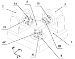
- the three-dimensional standard vibrator with leaf-spring-type decoupling device contains a base 1 , a X axis (horizontal and single-dimensional, similarly hereinafter) vibrator 2 , a Y axis (horizontal and single-dimensional, similarly hereinafter) vibrator 3 , a Z axis (vertical and single-dimensional, similarly hereinafter) vibrator 4 , a three-dimensional vibration platform 5 , and three decupling devices 6A , 6B and 6C along X, Y and Z axes respectively.
- the three vibrators 2 , 3 , 4 along X, Y and Z axis are all installed in the base 1 and connected with the three-dimensional vibration platform 5 through the three decoupling devices 6A , 6B and 6C correspondingly.
- the X axis decoupling device 6A is comprised of the first, second, third and fourth spring components 61 , 62 , 63 and 64 and a cruciform connector 65 .
- the first spring component 61 and the second spring component 62 constitute the first stage supporting-spring unit
- the third spring component 63 and the fourth spring component 64 constitute the second stage supporting-spring unit.
- the connector is used to connect the first stage supporting-spring unit and the second stage supporting-spring unit.
- the geometry of the connector could not be limited to cruciform type, but square type or rectangle type. Even though the embodiment has taken the illustration example of two stages supporting-spring units, the stage quantity could not be limited to two but changed based on the width of the single-dimensional vibrator and the three-dimensional vibration platform and the length of the supporting-spring unit.
- the first spring component 61 consists of leaf spring 611 and L-type platen 612.
- Four pieces of platens 612 are mounted on the two edges of the leaf spring 611 symmetrically.
- the L-type platens form the first and second connecting components.
- the first, second, third and fourth spring components 61, 62, 63 and 64 are all designed with the same geometries and installed into the connector 65.
- the properties of the installation are as follow.
- the first spring component 61 and the second spring component 62 whose spring planes are parallel with each other, are mounted on the first installation plane 651 of the connector 65 symmetrically to the connector center.
- the third spring component 63 and the fourth spring component 64 whose spring planes are parallel with each other, are mounted on the second installation plane 652 of the connector 65 symmetrically to the connector center.
- the spring planes from the first spring component 61 and the third spring component 63 are perpendicular to each other
- the spring planes from the second spring component 62 and the fourth spring component 64 are perpendicular to each other.
- the Y axis and Z axis decoupling device 6B and 6C are also leaf-spring-type motion decoupling devices, which are formed by two stages of supporting-spring units and designed with the same geometries and action mechanism of the X axis decoupling device 6A .
- one edge of the X axis decoupling device 6A is connected to the vibration platform 21 of the X axis vibrator 2 through the L-type platen 612.
- the other edge is connected to the three-dimensional vibration platform 5 .
- there are two spring planes have been chosen from the four supporting-spring units 61 , 62 , 63 and 64 to be horizontal direction, then the spring planes from the other two supporting-spring units are set to be vertical direction. Since the four spring planes are all perpendicular to the vibration platform 21 , the springs perform high stiffness properties when used for transmitting vibrations.
- the vibrations output from the vibration platform 21 of the X axis vibrator 2 could be transmitted precisely to the three-dimensional vibration platform 5.
- the vibrations output from the vibration platform 31 of the Y axis vibrator 3 could be transmitted precisely to the three-dimensional vibration platform 5.
- the motion decoupling device 6C which is used for transmitting the vibrations along Z axis
- there are two spring planes have been chosen from the four supporting-spring units 61, 62, 63 and 64 to be parallel with the vibration platform 21 of the X axis vibrator 2, and the spring planes from the other two supporting-spring units are set to be parallel with the vibration platform 31 of the Y axis vibrator 3.
- the four spring planes are all perpendicular to the vibration platform 41 of the Z axis vibrator 4.
- the springs When used for transmitting vibrations, the springs perform high stiffness properties, and the vibrations output from the vibration platform 41 of the Z axis vibrator 4 could be transmitted precisely to the three-dimensional vibration platform 5.
- the operating processes of the present invention are as follow. Take the vibrations output from the X axis vibrator 2 as an example. First, the vibrations are transmitted to the X axis decoupling device 6A, which is connected with the X axis vibrator 2. Since the planes of the two-stage springs from the decoupling device are all perpendicular to the vibration platform 21 of the X axis vibrator 2, the springs perform high stiffness properties. Then the vibrations can be transmitted precisely to the three-dimensional vibration platform 5, which is connected with the X axis decoupling device 6A.
- the planes of the springs from one stage supporting-spring unit are parallel with the vibration platform 31 of the Y axis vibrator 3, so the springs perform small stiffness properties and the output disturbances from the Y axis vibrator 3 to the X axis could be neglected.
- the planes of the springs from another stage supporting-spring unit are parallel to the vibration platform 41 of the Z axis vibrator 4, so the springs perform small stiffness properties and the output disturbances from the Z axis vibrator 4 to X axis could be neglected.
- the decoupled vibrations along X axis could be output by the three-dimensional vibration platform 5.
- the corresponding decoupled vibrations could also be output from the three-dimensional vibration platform 5 . Then the resultant vibrations along X, Y and Z axes are output by the three-dimensional vibration platform 5.
- the proposed three-dimensional vibrator consists of three leaf-spring-type decoupling devices and three single-dimensional vibrators.
- the leaf-spring-type decoupling devices are designed with intersecting springs, which can transmit the vibrations along the desired axis as well as ignore the disturbed vibrations output from the other axes.
- the motion decoupling of the output vibrations from the three-dimensional vibrator is realized.
Landscapes
- Physics & Mathematics (AREA)
- General Physics & Mathematics (AREA)
- Apparatuses For Generation Of Mechanical Vibrations (AREA)
- Vibration Prevention Devices (AREA)
Abstract
Description
- This present invention relates to a three-dimensional standard vibrator.
- Recently, the calibration of three-dimensional vibration sensor is usually based on a single dimension vibration calibration system, which calibrates the three axes of the sensor one after another. Inevitably, this method consumes too much time and complicates the data processing system. In the mean time, considering the cross-axis coupling of the three-dimensional sensor, it is hard to obtain the sensitivity matrix, which represents the coupling relations between the three axes of the sensor based on this method. So development of a three-dimensional standard vibrator, which output vibration exciting signals to the three axes of the three-dimensional sensor, has important theoretical and practical significance on the development of vibration sensor calibration technology and the progressing of related industry technology.
- Chinese patent
CN 201110207297.5 - The shortcomings of the proposed vibrator are as follow. The required accuracy of the assembling is excessively high since the first and second frameworks are mounted on the vibrator and the three-dimensional vibration platform respectively, and the two frameworks are inserted with each other with latch-type structure. Besides, the second framework increases the mass of the three-dimensional vibration platform and the stiffness of the gas film is relatively a restriction when used for vibration transmissions in high frequencies.
- To overcome the above shortcomings of the prior art, the present invention provides a three-dimensional standard vibrator based on leaf-spring-type decoupling device, which decreases the requirement of assembling accuracy and performs larger stiffness than the aerostatic gas film when transmitting vibrations.
- The three-dimensional standard vibrator based on leaf-spring-type decoupling device contains a base set with three single-dimensional vibrators (along X, Y and Z axes, respectively) and a three-dimensional vibration platform. The X axis vibrator is connected with the three-dimensional vibration platform through X axis decoupling device, the Y axis vibrator is connected with the three-dimensional vibration platform through Y axis decoupling device, and the Z axis vibrator is connected with the three-dimensional vibration platform through Z axis decoupling device.
- The properties of the three-dimensional vibrator are as follow. X axis decoupling device, Y axis decoupling device and Z axis decoupling device are all comprised of supporting-spring units. Each of the supporting-spring units contains a pair of leaf springs mounted parallel with each other and the first and second connecting components mounted on the two edges of the leaf springs. The first connecting component is near the vibrator and the second connecting component is near the three-dimensional vibration platform.
- In addition, X axis decoupling device, Y axis decoupling device and Z axis decoupling device are all comprised of two-stage supporting-spring units, which are connected in series with each other.
- In addition, the two stages of the supporting-spring units, whose leaf springs are orthogonally mounted, are fixed with each other through a connector.
- In addition, the connector is with the cruciform geometry, and the two-stage supporting-spring units are mounted on the two orthogonal arms of the connector, respectively.
- The leaf springs from one stage supporting-spring units are connected with the vibration platform of the corresponding single-dimensional vibrator through the first connecting component and the other leaf springs from another supporting-spring unit are connected with the three-dimensional vibration platform through the second connecting component. The planes of the leaf springs from the two-stage supporting-spring units are all mounted parallel to the axis of the corresponding single-dimensional vibrator, and the planes of the leaf springs from one stage of supporting-spring units are mounted perpendicular to the axis of another single-dimensional vibrator.
- In addition, the two connecting components are all comprised of a pair of L-type connecting pieces, and the connecting pieces are all drilled with screw holes for connecting bolts.
- The operating processes of the present invention are as follow. Since the three decoupling devices along X, Y and Z axes are all comprised of two-stage supporting-spring units, they could be regarded as leaf-spring-type motion decoupling devices. Take the vibrations output from the X axis vibrator as an example. First, the vibrations are transmitted to the X axis decoupling device, which is connected with the X axis vibrator. Since the planes of the two-stage springs from the decoupling device are all parallel with X axis, the springs perform high stiffness properties. Then the vibrations can be transmitted precisely to the three-dimensional vibration platform, which is connected with the X axis vibrator. At the same time, the planes of the springs from one stage supporting-spring unit are perpendicular to the operating axis of the Y axis vibrator, so the springs perform small stiffness properties and the output disturbances from the Y axis vibrator to X axis could be neglected. The planes of the springs from another stage supporting-spring unit are perpendicular to the operating axis of the Z axis vibrator, so the springs perform small stiffness properties and the output disturbances from the Z axis vibrator to X axis could be neglected. In summary, the decoupled vibrations along X axis could be output by the three-dimensional vibration platform. Similarly, for the vibrations output from the other two vibrators along Y and Z axes, the corresponding decoupled vibrations could also be output from the three-dimensional vibration platform. Then the resultant vibrations along X, Y and Z axes are output by the three-dimensional vibration platform.
- The proposed three-dimensional standard vibrator consists of three leaf-spring-type decoupling devices and three single-dimensional vibrators. The leaf-spring-type decoupling devices are designed with intersecting springs, which can transmit vibrations along the desired axis as well as ignore the disturbed vibrations output from the other axes. The motion decoupling of the output vibrations from the three-dimensional vibrator is realized.
- The advantages of the present invention are:
- 1. The supporting-spring units are fixed with the single-dimensional vibrators and the three-dimensional vibration platform by screw bolts directly, which means a simple connection, convenient positioning and simple installation.
- 2. Along the desired vibration output axis, the vibration transmission stiffness of the leaf-spring-type decoupling device is much higher than the conventional aerostatic gas film, so the upper limit operating frequency of the proposed three-dimensional standard vibrator is increased dramatically, the structure of the three-dimensional motion decoupling device is simplified, and the whole cost of the three-dimensional standard vibrator is decreased.
-
-
Fig. 1 is a schematic structure of the three-dimensional standard vibrator. -
Fig. 2 is a structure diagram of the leaf-spring-type motion decoupling device. -
Fig. 3 is a structure diagram of the supporting-spring unit. -
Fig. 4 is a structure diagram of the connector. - Hereinafter, further embodiments of the present invention will be described with reference to the accompanying drawings.
- As shown in
Fig. 1 , the three-dimensional standard vibrator with leaf-spring-type decoupling device contains abase 1, a X axis (horizontal and single-dimensional, similarly hereinafter)vibrator 2, a Y axis (horizontal and single-dimensional, similarly hereinafter)vibrator 3, a Z axis (vertical and single-dimensional, similarly hereinafter)vibrator 4, a three-dimensional vibration platform 5, and three decuplingdevices vibrators base 1 and connected with the three-dimensional vibration platform 5 through the threedecoupling devices - As shown in
Fig. 2 , the Xaxis decoupling device 6A is comprised of the first, second, third andfourth spring components cruciform connector 65. Thefirst spring component 61 and thesecond spring component 62 constitute the first stage supporting-spring unit, and thethird spring component 63 and thefourth spring component 64 constitute the second stage supporting-spring unit. The connector is used to connect the first stage supporting-spring unit and the second stage supporting-spring unit. As long as the orthogonal installation of the two stages supporting-spring units could be realized, the geometry of the connector could not be limited to cruciform type, but square type or rectangle type. Even though the embodiment has taken the illustration example of two stages supporting-spring units, the stage quantity could not be limited to two but changed based on the width of the single-dimensional vibrator and the three-dimensional vibration platform and the length of the supporting-spring unit. - As shown in
Fig. 3 , thefirst spring component 61 consists ofleaf spring 611 and L-type platen 612. Four pieces ofplatens 612 are mounted on the two edges of theleaf spring 611 symmetrically. The L-type platens form the first and second connecting components. - As shown in
Fig. 2 ,Fig. 3 and Fig. 4 , the first, second, third andfourth spring components connector 65. The properties of the installation are as follow. Thefirst spring component 61 and thesecond spring component 62, whose spring planes are parallel with each other, are mounted on thefirst installation plane 651 of theconnector 65 symmetrically to the connector center. Thethird spring component 63 and thefourth spring component 64, whose spring planes are parallel with each other, are mounted on thesecond installation plane 652 of theconnector 65 symmetrically to the connector center. In addition, the spring planes from thefirst spring component 61 and thethird spring component 63 are perpendicular to each other, the spring planes from thesecond spring component 62 and thefourth spring component 64 are perpendicular to each other. - The Y axis and Z
axis decoupling device axis decoupling device 6A. - For the vibrations along X axis output from the three-dimensional standard vibrator, one edge of the X
axis decoupling device 6A is connected to thevibration platform 21 of theX axis vibrator 2 through the L-type platen 612. The other edge is connected to the three-dimensional vibration platform 5. In the meantime, there are two spring planes have been chosen from the four supporting-spring units vibration platform 21, the springs perform high stiffness properties when used for transmitting vibrations. Then the vibrations output from thevibration platform 21 of theX axis vibrator 2 could be transmitted precisely to the three-dimensional vibration platform 5. Similarly, under the effect of the Yaxis decoupling device 6B, the vibrations output from thevibration platform 31 of theY axis vibrator 3 could be transmitted precisely to the three-dimensional vibration platform 5. - For the
motion decoupling device 6C, which is used for transmitting the vibrations along Z axis, there are two spring planes have been chosen from the four supporting-spring units vibration platform 21 of theX axis vibrator 2, and the spring planes from the other two supporting-spring units are set to be parallel with thevibration platform 31 of theY axis vibrator 3. Then the four spring planes are all perpendicular to thevibration platform 41 of theZ axis vibrator 4. When used for transmitting vibrations, the springs perform high stiffness properties, and the vibrations output from thevibration platform 41 of theZ axis vibrator 4 could be transmitted precisely to the three-dimensional vibration platform 5. - The operating processes of the present invention are as follow. Take the vibrations output from the
X axis vibrator 2 as an example. First, the vibrations are transmitted to the Xaxis decoupling device 6A, which is connected with theX axis vibrator 2. Since the planes of the two-stage springs from the decoupling device are all perpendicular to thevibration platform 21 of theX axis vibrator 2, the springs perform high stiffness properties. Then the vibrations can be transmitted precisely to the three-dimensional vibration platform 5, which is connected with the Xaxis decoupling device 6A. At the same time, the planes of the springs from one stage supporting-spring unit are parallel with thevibration platform 31 of theY axis vibrator 3, so the springs perform small stiffness properties and the output disturbances from theY axis vibrator 3 to the X axis could be neglected. The planes of the springs from another stage supporting-spring unit are parallel to thevibration platform 41 of theZ axis vibrator 4, so the springs perform small stiffness properties and the output disturbances from theZ axis vibrator 4 to X axis could be neglected. In summary, the decoupled vibrations along X axis could be output by the three-dimensional vibration platform 5. Similarly, for the vibrations output from the other twovibrators dimensional vibration platform 5. Then the resultant vibrations along X, Y and Z axes are output by the three-dimensional vibration platform 5. - The proposed three-dimensional vibrator consists of three leaf-spring-type decoupling devices and three single-dimensional vibrators. The leaf-spring-type decoupling devices are designed with intersecting springs, which can transmit the vibrations along the desired axis as well as ignore the disturbed vibrations output from the other axes. The motion decoupling of the output vibrations from the three-dimensional vibrator is realized.
- The advantages of the present invention are:
- 1. The supporting-spring units are fixed with the single-dimensional vibrators and the three-dimensional vibration platform by screw bolts directly, which means a simple connection, convenient positioning and simple installation.
- 2. Along the desired vibration output axis, the vibration transmission stiffness of the leaf-spring-type decoupling device is much higher than the conventional aerostatic gas film, so the upper limit operating frequency of the proposed three-dimensional standard vibrator is increased dramatically, the structure of the three-dimensional vibration decoupling device is simplified, and the whole cost of the three-dimensional standard vibrator is decreased.
- The specific embodiments discussed are merely illustrative of specific ways to make and use the invention, and do not limit the scope of the invention. Meanwhile, it should be appreciated that various modifications and their equivalents can be devised by those skilled in the art and will fall within the spirit and scope of the principles of the disclosure.
Claims (5)
- The three-dimensional standard vibrator based on leaf-spring-type decoupling device contains a base set with three single-dimensional vibrators (along X, Y and Z axes, respectively) and a three-dimensional vibration platform. The X axis vibrator is connected with the three-dimensional vibration platform through X axis decoupling device, the Y axis vibrator is connected with the three-dimensional vibration platform through Y axis decoupling device, and the Z axis vibrator is connected with the three-dimensional vibration platform through Z axis decoupling device. The properties of the three-dimensional vibrator are as follow. X axis decoupling device, Y axis decoupling device and Z axis decoupling device are all comprised of supporting-spring units. Each of the supporting-spring units contains a pair of leaf springs mounted parallel with each other and the first and second connecting components mounted on the two edges of the leaf springs. The first connecting component is near the vibrator and the second connecting component is near the three-dimensional vibration platform.
- The three-dimensional vibrator with leaf-spring-based decoupling device according to claim 1, wherein the properties are: X axis decoupling device, Y axis decoupling device and Z axis decoupling device are all comprised of two-stage supporting-spring units, which are connected in series with each other.
- The three-dimensional vibrator with leaf-spring-based decoupling device according to claim 2, wherein the properties are: the two stages of the supporting-spring units, whose leaf springs are orthogonally mounted, are fixed with each other through a connector.
- The three-dimensional vibrator with leaf-spring-based decoupling device according to claim 2, wherein the properties are: the connector is with the cruciform geometry, and the two-stage supporting-spring units are mounted on the two orthogonal arms of the connector, respectively.
- The three-dimensional vibrator with leaf-spring-based decoupling device according to claim 4, wherein the properties are: the two connecting components are all comprised of a pair of L-type connecting pieces, and the connecting pieces are all drilled with screw holes for connecting bolts.
Applications Claiming Priority (2)
| Application Number | Priority Date | Filing Date | Title |
|---|---|---|---|
| CN201510019692.9A CN104596720B (en) | 2015-01-15 | 2015-01-15 | Three-component standard vibration machine based on reed-type decoupling device |
| PCT/CN2015/087344 WO2016112686A1 (en) | 2015-01-15 | 2015-08-18 | Three-component standard shaker based on spring-type decoupling device |
Publications (3)
| Publication Number | Publication Date |
|---|---|
| EP3246687A1 true EP3246687A1 (en) | 2017-11-22 |
| EP3246687A4 EP3246687A4 (en) | 2018-12-05 |
| EP3246687B1 EP3246687B1 (en) | 2020-07-29 |
Family
ID=53122646
Family Applications (1)
| Application Number | Title | Priority Date | Filing Date |
|---|---|---|---|
| EP15877599.9A Active EP3246687B1 (en) | 2015-01-15 | 2015-08-18 | Three-component standard shaker based on spring-type decoupling device |
Country Status (5)
| Country | Link |
|---|---|
| US (1) | US10365181B2 (en) |
| EP (1) | EP3246687B1 (en) |
| JP (1) | JP6261829B1 (en) |
| CN (1) | CN104596720B (en) |
| WO (1) | WO2016112686A1 (en) |
Cited By (2)
| Publication number | Priority date | Publication date | Assignee | Title |
|---|---|---|---|---|
| JP6261829B1 (en) * | 2015-01-15 | 2018-01-17 | 浙江大学Zhejiang University | Three-dimensional standard shaking table based on leaf spring type decoupling device |
| CN108362460A (en) * | 2018-04-08 | 2018-08-03 | 天津大学 | A kind of multidirectional adjustable rigidity spring suitable for multiple spot shaketalle test simulating boundary |
Families Citing this family (11)
| Publication number | Priority date | Publication date | Assignee | Title |
|---|---|---|---|---|
| CN105127987B (en) * | 2015-10-20 | 2020-08-07 | 山东理工大学 | Planar kinematic decoupled parallel robot |
| CN109530198B (en) * | 2019-01-10 | 2024-04-09 | 河北工业大学 | Wedge-shaped pre-tightening two-dimensional compliant vibration platform |
| CN109622348B (en) * | 2019-01-31 | 2020-07-24 | 天津大学 | Three-dimensional decoupling ultrasonic nano vibration table |
| KR102234817B1 (en) * | 2019-07-11 | 2021-04-01 | 한양대학교 산학협력단 | Apparatus for analysing of multi blade system and method for the same |
| CN111272367B (en) * | 2020-02-21 | 2025-01-28 | 天津大学 | An embedded vibration table with expandable frequency and area for large load tests |
| CN111337215A (en) * | 2020-02-21 | 2020-06-26 | 天津大学 | A Modular Shaking Table With Extensible Frequency and Area for Large Load Tests |
| CN113532782B (en) * | 2021-08-03 | 2024-12-24 | 北京航天希尔测试技术有限公司 | An eight-drive six-degree-of-freedom electric vibration test device with adjustable spatial posture |
| CN115585972B (en) * | 2022-08-19 | 2025-08-12 | 航天科工防御技术研究试验中心 | Adjustable vibration flexible decoupling device, test system and decoupling method |
| CN115751107A (en) * | 2022-11-29 | 2023-03-07 | 济南汉江光电科技有限公司 | Three-dimensional feed-in adjusting device with vacuum suction decoupling function |
| CN118362076B (en) * | 2023-09-14 | 2026-02-03 | 西安工业大学 | Three-way homopolar scanning measuring head |
| CN122142322A (en) * | 2026-04-30 | 2026-06-05 | 崇义章源钨业股份有限公司 | A device and method for improving the uniformity of powder density in tungsten rods |
Family Cites Families (25)
| Publication number | Priority date | Publication date | Assignee | Title |
|---|---|---|---|---|
| US2364316A (en) * | 1944-02-07 | 1944-12-05 | Robert R Royal | Grappling hook |
| US3952980A (en) * | 1974-10-29 | 1976-04-27 | The United States Of America As Represented By The Administrator Of The National Aeronautics And Space Administration | Translatory shock absorber for attitude sensors |
| US4085825A (en) | 1975-04-03 | 1978-04-25 | Rockwell International Corporation | Vibratory system isolation and flexure pivot |
| JPS6288933A (en) * | 1985-10-15 | 1987-04-23 | Hitachi Ltd | Electrodynamic three-dimensional vibration testing machine |
| DE3917408A1 (en) * | 1988-06-06 | 1989-12-07 | Takenaka Corp | DAMPING BASE |
| US5988359A (en) * | 1997-02-24 | 1999-11-23 | Graham; S. Neal | Vibratory drive unit and associated parts feeder bowl |
| JP3413482B2 (en) * | 1999-10-07 | 2003-06-03 | 株式会社サンエス | 3-axis vibration test equipment |
| US6860152B2 (en) * | 2002-04-26 | 2005-03-01 | Team Corporation | High frequency multiple degree of freedom vibration test machine |
| JP2005327532A (en) * | 2004-05-13 | 2005-11-24 | Hitachi Ltd | Fuel cell, fuel cell separator unit kit, and fuel cell power generation unit kit |
| JP2006118968A (en) * | 2004-10-21 | 2006-05-11 | A & D Co Ltd | Multiaxial excitation apparatus for vibration test |
| JP5376780B2 (en) * | 2007-08-08 | 2013-12-25 | 株式会社東芝 | Piezoelectric motor and camera device |
| CN201138277Y (en) * | 2007-12-29 | 2008-10-22 | 苏州试验仪器总厂 | Connecting apparatus for multiple synchronous spring plates |
| CN101572945B (en) * | 2008-04-29 | 2011-08-24 | 中国移动通信集团公司 | Method and device for confirming sending resource of channel quality indication |
| CN102478449A (en) * | 2010-11-25 | 2012-05-30 | 北京航天斯达新技术装备公司 | Triaxial mechanical decoupling device and vibration testing system |
| DE102011000656B8 (en) * | 2011-02-11 | 2013-03-21 | Deutsches Zentrum für Luft- und Raumfahrt e.V. | Vibration-free mounting of an object on a vibrating structure |
| DE102011015800A1 (en) * | 2011-04-01 | 2012-10-04 | Fraunhofer-Gesellschaft zur Förderung der angewandten Forschung e.V. | Device for mechanical vibration decoupling |
| CN102364316B (en) * | 2011-07-23 | 2013-08-14 | 浙江大学 | Three-component standard vibration table based on lock type decoupling device |
| CN102865985B (en) | 2012-09-03 | 2015-12-09 | 江苏大学 | A kind of space three translation based on flexible joint exciting vibrating device in parallel |
| CN102865987B (en) * | 2012-09-17 | 2015-01-07 | 苏州苏试试验仪器股份有限公司 | Plane static pressure type vibration transferring and decoupling device and tri-axial vibration composite experiment table |
| KR101345869B1 (en) * | 2012-12-18 | 2013-12-30 | 주식회사 현대케피코 | Three dimensional vibration tester |
| CN103062284B (en) * | 2012-12-19 | 2015-02-11 | 哈尔滨工业大学 | Zero-rigidity vibration isolator of double-layer air-flotation orthogonal decoupling and flexible film angle decoupling |
| CN103912766B (en) * | 2014-03-28 | 2015-10-28 | 南京航空航天大学 | Planar three freedom piezoelectric drive platform and motion driving method thereof |
| CN104614137B (en) * | 2015-01-15 | 2016-08-31 | 浙江大学 | Three-component standard vibration machine based on static pressure air-bearing decoupling device |
| CN104596720B (en) * | 2015-01-15 | 2017-08-08 | 浙江大学 | Three-component standard vibration machine based on reed-type decoupling device |
| CN204556207U (en) * | 2015-01-15 | 2015-08-12 | 浙江大学 | Based on the three-component standard vibration machine of reed-type decoupling device |
-
2015
- 2015-01-15 CN CN201510019692.9A patent/CN104596720B/en active Active
- 2015-08-18 WO PCT/CN2015/087344 patent/WO2016112686A1/en not_active Ceased
- 2015-08-18 JP JP2017536238A patent/JP6261829B1/en active Active
- 2015-08-18 EP EP15877599.9A patent/EP3246687B1/en active Active
- 2015-08-18 US US15/542,639 patent/US10365181B2/en active Active
Cited By (4)
| Publication number | Priority date | Publication date | Assignee | Title |
|---|---|---|---|---|
| JP6261829B1 (en) * | 2015-01-15 | 2018-01-17 | 浙江大学Zhejiang University | Three-dimensional standard shaking table based on leaf spring type decoupling device |
| JP2018508755A (en) * | 2015-01-15 | 2018-03-29 | 浙江大学Zhejiang University | Three-dimensional standard shaking table based on leaf spring type decoupling device |
| CN108362460A (en) * | 2018-04-08 | 2018-08-03 | 天津大学 | A kind of multidirectional adjustable rigidity spring suitable for multiple spot shaketalle test simulating boundary |
| CN108362460B (en) * | 2018-04-08 | 2022-12-27 | 天津大学 | Multidirectional adjustable stiffness spring suitable for multipoint shaking table test simulation boundary |
Also Published As
| Publication number | Publication date |
|---|---|
| EP3246687A4 (en) | 2018-12-05 |
| US10365181B2 (en) | 2019-07-30 |
| WO2016112686A1 (en) | 2016-07-21 |
| EP3246687B1 (en) | 2020-07-29 |
| CN104596720B (en) | 2017-08-08 |
| JP6261829B1 (en) | 2018-01-17 |
| CN104596720A (en) | 2015-05-06 |
| JP2018508755A (en) | 2018-03-29 |
| US20180106699A1 (en) | 2018-04-19 |
Similar Documents
| Publication | Publication Date | Title |
|---|---|---|
| US10365181B2 (en) | Three-dimensional standard vibrator based on leaf-spring-type decoupling device | |
| US10422717B2 (en) | Three-dimensional standard vibrator based on aerostatic gas-floating decoupling device | |
| US10473686B2 (en) | Inertia measurement module and triaxial accelerometer | |
| CN101299005A (en) | Three-axis vibration test apparatus | |
| CN102322944B (en) | Tricomponent vibration calibrating device | |
| CN105889385B (en) | A kind of compressed spring type six degree of freedom quasi-zero stiffness vibration isolators and its design method | |
| CN110440798A (en) | High-precision integrated micro-inertial measurement unit and inertial navigation system | |
| CN102364316B (en) | Three-component standard vibration table based on lock type decoupling device | |
| CN101825426A (en) | Capacitive displacement transducer | |
| CN106500940A (en) | Six-degree of freedom vibration acceleration measurement device | |
| CN203414164U (en) | Vibration detection device for bubble flow passage with controllable state of flow field | |
| CN204556207U (en) | Based on the three-component standard vibration machine of reed-type decoupling device | |
| CN202195878U (en) | Three-component standard vibration table based on lock type decoupling device | |
| CN109029431B (en) | Triaxial multi-stage PCB vibration reduction structure for MEMS inertial measurement system | |
| CN204731265U (en) | A kind of MEMS triaxial accelerometer | |
| CN104280569B (en) | Three-dimensional integrated micromachined acceleration sensor and manufacturing method for suppressing lateral interference | |
| TWI470228B (en) | Accelerometer | |
| CN103424176B (en) | Bubble flow channel vibration detecting device with controllable flow field state | |
| CN207248474U (en) | UHV DC wall bushing anti-seismic test device | |
| CN112709780B (en) | Novel vibration isolator with hinge type angular displacement-free mechanism | |
| CN103742580A (en) | Method for adjusting intrinsic frequency of vibration isolation system of inertial navigation assembly | |
| CN115574807A (en) | Navigation control system based on MEMS inertial device | |
| CN207292456U (en) | Inertial measurement system and unmanned plane | |
| CN106197768B (en) | A high-precision piezoelectric three-way force sensor | |
| CN110230659B (en) | Periodic vertical vibration isolation device |
Legal Events
| Date | Code | Title | Description |
|---|---|---|---|
| STAA | Information on the status of an ep patent application or granted ep patent |
Free format text: STATUS: THE INTERNATIONAL PUBLICATION HAS BEEN MADE |
|
| PUAI | Public reference made under article 153(3) epc to a published international application that has entered the european phase |
Free format text: ORIGINAL CODE: 0009012 |
|
| STAA | Information on the status of an ep patent application or granted ep patent |
Free format text: STATUS: REQUEST FOR EXAMINATION WAS MADE |
|
| 17P | Request for examination filed |
Effective date: 20170929 |
|
| AK | Designated contracting states |
Kind code of ref document: A1 Designated state(s): AL AT BE BG CH CY CZ DE DK EE ES FI FR GB GR HR HU IE IS IT LI LT LU LV MC MK MT NL NO PL PT RO RS SE SI SK SM TR |
|
| AX | Request for extension of the european patent |
Extension state: BA ME |
|
| DAV | Request for validation of the european patent (deleted) | ||
| DAX | Request for extension of the european patent (deleted) | ||
| A4 | Supplementary search report drawn up and despatched |
Effective date: 20181030 |
|
| RIC1 | Information provided on ipc code assigned before grant |
Ipc: G01M 7/06 20060101AFI20181022BHEP |
|
| STAA | Information on the status of an ep patent application or granted ep patent |
Free format text: STATUS: EXAMINATION IS IN PROGRESS |
|
| 17Q | First examination report despatched |
Effective date: 20200220 |
|
| GRAP | Despatch of communication of intention to grant a patent |
Free format text: ORIGINAL CODE: EPIDOSNIGR1 |
|
| STAA | Information on the status of an ep patent application or granted ep patent |
Free format text: STATUS: GRANT OF PATENT IS INTENDED |
|
| INTG | Intention to grant announced |
Effective date: 20200526 |
|
| GRAS | Grant fee paid |
Free format text: ORIGINAL CODE: EPIDOSNIGR3 |
|
| GRAA | (expected) grant |
Free format text: ORIGINAL CODE: 0009210 |
|
| STAA | Information on the status of an ep patent application or granted ep patent |
Free format text: STATUS: THE PATENT HAS BEEN GRANTED |
|
| AK | Designated contracting states |
Kind code of ref document: B1 Designated state(s): AL AT BE BG CH CY CZ DE DK EE ES FI FR GB GR HR HU IE IS IT LI LT LU LV MC MK MT NL NO PL PT RO RS SE SI SK SM TR |
|
| REG | Reference to a national code |
Ref country code: CH Ref legal event code: EP |
|
| REG | Reference to a national code |
Ref country code: AT Ref legal event code: REF Ref document number: 1296348 Country of ref document: AT Kind code of ref document: T Effective date: 20200815 |
|
| REG | Reference to a national code |
Ref country code: IE Ref legal event code: FG4D |
|
| REG | Reference to a national code |
Ref country code: DE Ref legal event code: R096 Ref document number: 602015056700 Country of ref document: DE |
|
| REG | Reference to a national code |
Ref country code: LT Ref legal event code: MG4D |
|
| REG | Reference to a national code |
Ref country code: NL Ref legal event code: MP Effective date: 20200729 |
|
| REG | Reference to a national code |
Ref country code: AT Ref legal event code: MK05 Ref document number: 1296348 Country of ref document: AT Kind code of ref document: T Effective date: 20200729 |
|
| PG25 | Lapsed in a contracting state [announced via postgrant information from national office to epo] |
Ref country code: HR Free format text: LAPSE BECAUSE OF FAILURE TO SUBMIT A TRANSLATION OF THE DESCRIPTION OR TO PAY THE FEE WITHIN THE PRESCRIBED TIME-LIMIT Effective date: 20200729 Ref country code: BG Free format text: LAPSE BECAUSE OF FAILURE TO SUBMIT A TRANSLATION OF THE DESCRIPTION OR TO PAY THE FEE WITHIN THE PRESCRIBED TIME-LIMIT Effective date: 20201029 Ref country code: ES Free format text: LAPSE BECAUSE OF FAILURE TO SUBMIT A TRANSLATION OF THE DESCRIPTION OR TO PAY THE FEE WITHIN THE PRESCRIBED TIME-LIMIT Effective date: 20200729 Ref country code: LT Free format text: LAPSE BECAUSE OF FAILURE TO SUBMIT A TRANSLATION OF THE DESCRIPTION OR TO PAY THE FEE WITHIN THE PRESCRIBED TIME-LIMIT Effective date: 20200729 Ref country code: GR Free format text: LAPSE BECAUSE OF FAILURE TO SUBMIT A TRANSLATION OF THE DESCRIPTION OR TO PAY THE FEE WITHIN THE PRESCRIBED TIME-LIMIT Effective date: 20201030 Ref country code: SE Free format text: LAPSE BECAUSE OF FAILURE TO SUBMIT A TRANSLATION OF THE DESCRIPTION OR TO PAY THE FEE WITHIN THE PRESCRIBED TIME-LIMIT Effective date: 20200729 Ref country code: AT Free format text: LAPSE BECAUSE OF FAILURE TO SUBMIT A TRANSLATION OF THE DESCRIPTION OR TO PAY THE FEE WITHIN THE PRESCRIBED TIME-LIMIT Effective date: 20200729 Ref country code: PT Free format text: LAPSE BECAUSE OF FAILURE TO SUBMIT A TRANSLATION OF THE DESCRIPTION OR TO PAY THE FEE WITHIN THE PRESCRIBED TIME-LIMIT Effective date: 20201130 Ref country code: NO Free format text: LAPSE BECAUSE OF FAILURE TO SUBMIT A TRANSLATION OF THE DESCRIPTION OR TO PAY THE FEE WITHIN THE PRESCRIBED TIME-LIMIT Effective date: 20201029 Ref country code: FI Free format text: LAPSE BECAUSE OF FAILURE TO SUBMIT A TRANSLATION OF THE DESCRIPTION OR TO PAY THE FEE WITHIN THE PRESCRIBED TIME-LIMIT Effective date: 20200729 |
|
| PG25 | Lapsed in a contracting state [announced via postgrant information from national office to epo] |
Ref country code: PL Free format text: LAPSE BECAUSE OF FAILURE TO SUBMIT A TRANSLATION OF THE DESCRIPTION OR TO PAY THE FEE WITHIN THE PRESCRIBED TIME-LIMIT Effective date: 20200729 Ref country code: RS Free format text: LAPSE BECAUSE OF FAILURE TO SUBMIT A TRANSLATION OF THE DESCRIPTION OR TO PAY THE FEE WITHIN THE PRESCRIBED TIME-LIMIT Effective date: 20200729 Ref country code: LV Free format text: LAPSE BECAUSE OF FAILURE TO SUBMIT A TRANSLATION OF THE DESCRIPTION OR TO PAY THE FEE WITHIN THE PRESCRIBED TIME-LIMIT Effective date: 20200729 Ref country code: IS Free format text: LAPSE BECAUSE OF FAILURE TO SUBMIT A TRANSLATION OF THE DESCRIPTION OR TO PAY THE FEE WITHIN THE PRESCRIBED TIME-LIMIT Effective date: 20201129 |
|
| PG25 | Lapsed in a contracting state [announced via postgrant information from national office to epo] |
Ref country code: NL Free format text: LAPSE BECAUSE OF FAILURE TO SUBMIT A TRANSLATION OF THE DESCRIPTION OR TO PAY THE FEE WITHIN THE PRESCRIBED TIME-LIMIT Effective date: 20200729 |
|
| REG | Reference to a national code |
Ref country code: CH Ref legal event code: PL |
|
| PG25 | Lapsed in a contracting state [announced via postgrant information from national office to epo] |
Ref country code: LU Free format text: LAPSE BECAUSE OF NON-PAYMENT OF DUE FEES Effective date: 20200818 Ref country code: LI Free format text: LAPSE BECAUSE OF NON-PAYMENT OF DUE FEES Effective date: 20200831 Ref country code: EE Free format text: LAPSE BECAUSE OF FAILURE TO SUBMIT A TRANSLATION OF THE DESCRIPTION OR TO PAY THE FEE WITHIN THE PRESCRIBED TIME-LIMIT Effective date: 20200729 Ref country code: SM Free format text: LAPSE BECAUSE OF FAILURE TO SUBMIT A TRANSLATION OF THE DESCRIPTION OR TO PAY THE FEE WITHIN THE PRESCRIBED TIME-LIMIT Effective date: 20200729 Ref country code: RO Free format text: LAPSE BECAUSE OF FAILURE TO SUBMIT A TRANSLATION OF THE DESCRIPTION OR TO PAY THE FEE WITHIN THE PRESCRIBED TIME-LIMIT Effective date: 20200729 Ref country code: CZ Free format text: LAPSE BECAUSE OF FAILURE TO SUBMIT A TRANSLATION OF THE DESCRIPTION OR TO PAY THE FEE WITHIN THE PRESCRIBED TIME-LIMIT Effective date: 20200729 Ref country code: CH Free format text: LAPSE BECAUSE OF NON-PAYMENT OF DUE FEES Effective date: 20200831 Ref country code: DK Free format text: LAPSE BECAUSE OF FAILURE TO SUBMIT A TRANSLATION OF THE DESCRIPTION OR TO PAY THE FEE WITHIN THE PRESCRIBED TIME-LIMIT Effective date: 20200729 Ref country code: IT Free format text: LAPSE BECAUSE OF FAILURE TO SUBMIT A TRANSLATION OF THE DESCRIPTION OR TO PAY THE FEE WITHIN THE PRESCRIBED TIME-LIMIT Effective date: 20200729 |
|
| REG | Reference to a national code |
Ref country code: DE Ref legal event code: R097 Ref document number: 602015056700 Country of ref document: DE |
|
| REG | Reference to a national code |
Ref country code: BE Ref legal event code: MM Effective date: 20200831 |
|
| PG25 | Lapsed in a contracting state [announced via postgrant information from national office to epo] |
Ref country code: AL Free format text: LAPSE BECAUSE OF FAILURE TO SUBMIT A TRANSLATION OF THE DESCRIPTION OR TO PAY THE FEE WITHIN THE PRESCRIBED TIME-LIMIT Effective date: 20200729 |
|
| PLBE | No opposition filed within time limit |
Free format text: ORIGINAL CODE: 0009261 |
|
| STAA | Information on the status of an ep patent application or granted ep patent |
Free format text: STATUS: NO OPPOSITION FILED WITHIN TIME LIMIT |
|
| PG25 | Lapsed in a contracting state [announced via postgrant information from national office to epo] |
Ref country code: SK Free format text: LAPSE BECAUSE OF FAILURE TO SUBMIT A TRANSLATION OF THE DESCRIPTION OR TO PAY THE FEE WITHIN THE PRESCRIBED TIME-LIMIT Effective date: 20200729 |
|
| 26N | No opposition filed |
Effective date: 20210430 |
|
| PG25 | Lapsed in a contracting state [announced via postgrant information from national office to epo] |
Ref country code: BE Free format text: LAPSE BECAUSE OF NON-PAYMENT OF DUE FEES Effective date: 20200831 Ref country code: SI Free format text: LAPSE BECAUSE OF FAILURE TO SUBMIT A TRANSLATION OF THE DESCRIPTION OR TO PAY THE FEE WITHIN THE PRESCRIBED TIME-LIMIT Effective date: 20200729 Ref country code: IE Free format text: LAPSE BECAUSE OF NON-PAYMENT OF DUE FEES Effective date: 20200818 |
|
| PG25 | Lapsed in a contracting state [announced via postgrant information from national office to epo] |
Ref country code: TR Free format text: LAPSE BECAUSE OF FAILURE TO SUBMIT A TRANSLATION OF THE DESCRIPTION OR TO PAY THE FEE WITHIN THE PRESCRIBED TIME-LIMIT Effective date: 20200729 Ref country code: MT Free format text: LAPSE BECAUSE OF FAILURE TO SUBMIT A TRANSLATION OF THE DESCRIPTION OR TO PAY THE FEE WITHIN THE PRESCRIBED TIME-LIMIT Effective date: 20200729 Ref country code: CY Free format text: LAPSE BECAUSE OF FAILURE TO SUBMIT A TRANSLATION OF THE DESCRIPTION OR TO PAY THE FEE WITHIN THE PRESCRIBED TIME-LIMIT Effective date: 20200729 |
|
| PG25 | Lapsed in a contracting state [announced via postgrant information from national office to epo] |
Ref country code: MK Free format text: LAPSE BECAUSE OF FAILURE TO SUBMIT A TRANSLATION OF THE DESCRIPTION OR TO PAY THE FEE WITHIN THE PRESCRIBED TIME-LIMIT Effective date: 20200729 Ref country code: MC Free format text: LAPSE BECAUSE OF FAILURE TO SUBMIT A TRANSLATION OF THE DESCRIPTION OR TO PAY THE FEE WITHIN THE PRESCRIBED TIME-LIMIT Effective date: 20200729 |
|
| PGFP | Annual fee paid to national office [announced via postgrant information from national office to epo] |
Ref country code: DE Payment date: 20250812 Year of fee payment: 11 |
|
| PGFP | Annual fee paid to national office [announced via postgrant information from national office to epo] |
Ref country code: GB Payment date: 20250826 Year of fee payment: 11 |
|
| PGFP | Annual fee paid to national office [announced via postgrant information from national office to epo] |
Ref country code: FR Payment date: 20250828 Year of fee payment: 11 |