EP3246583B1 - Water-lubricated bearing material - Google Patents
Water-lubricated bearing material Download PDFInfo
- Publication number
- EP3246583B1 EP3246583B1 EP16737315.8A EP16737315A EP3246583B1 EP 3246583 B1 EP3246583 B1 EP 3246583B1 EP 16737315 A EP16737315 A EP 16737315A EP 3246583 B1 EP3246583 B1 EP 3246583B1
- Authority
- EP
- European Patent Office
- Prior art keywords
- carbon fiber
- resin
- ptfe
- bearing material
- lubrication type
- Prior art date
- Legal status (The legal status is an assumption and is not a legal conclusion. Google has not performed a legal analysis and makes no representation as to the accuracy of the status listed.)
- Active
Links
- 239000000463 material Substances 0.000 title claims description 64
- 229920000049 Carbon (fiber) Polymers 0.000 claims description 100
- 239000004917 carbon fiber Substances 0.000 claims description 100
- VNWKTOKETHGBQD-UHFFFAOYSA-N methane Chemical compound C VNWKTOKETHGBQD-UHFFFAOYSA-N 0.000 claims description 95
- 229920001343 polytetrafluoroethylene Polymers 0.000 claims description 81
- 239000004810 polytetrafluoroethylene Substances 0.000 claims description 81
- 229920005989 resin Polymers 0.000 claims description 68
- 239000011347 resin Substances 0.000 claims description 68
- 238000005461 lubrication Methods 0.000 claims description 46
- XLYOFNOQVPJJNP-UHFFFAOYSA-N water Substances O XLYOFNOQVPJJNP-UHFFFAOYSA-N 0.000 claims description 43
- 229920006026 co-polymeric resin Polymers 0.000 claims description 9
- -1 polytetrafluoroethylene Polymers 0.000 claims description 8
- 150000001875 compounds Chemical class 0.000 claims description 3
- 229920001577 copolymer Polymers 0.000 claims description 3
- QQONPFPTGQHPMA-UHFFFAOYSA-N propylene Natural products CC=C QQONPFPTGQHPMA-UHFFFAOYSA-N 0.000 claims description 3
- 125000004805 propylene group Chemical group [H]C([H])([H])C([H])([*:1])C([H])([H])[*:2] 0.000 claims description 3
- BFKJFAAPBSQJPD-UHFFFAOYSA-N tetrafluoroethene Chemical group FC(F)=C(F)F BFKJFAAPBSQJPD-UHFFFAOYSA-N 0.000 claims description 3
- 239000000155 melt Substances 0.000 claims description 2
- 238000012360 testing method Methods 0.000 description 46
- 238000002156 mixing Methods 0.000 description 44
- 239000011342 resin composition Substances 0.000 description 20
- 239000002994 raw material Substances 0.000 description 19
- 239000011295 pitch Substances 0.000 description 18
- 239000000945 filler Substances 0.000 description 11
- 238000011156 evaluation Methods 0.000 description 10
- 239000000835 fiber Substances 0.000 description 10
- 238000000034 method Methods 0.000 description 10
- 238000005259 measurement Methods 0.000 description 7
- 229910052799 carbon Inorganic materials 0.000 description 6
- 239000003921 oil Substances 0.000 description 6
- OKTJSMMVPCPJKN-UHFFFAOYSA-N Carbon Chemical compound [C] OKTJSMMVPCPJKN-UHFFFAOYSA-N 0.000 description 5
- 238000005336 cracking Methods 0.000 description 5
- 239000010687 lubricating oil Substances 0.000 description 5
- 239000004698 Polyethylene Substances 0.000 description 4
- 230000000052 comparative effect Effects 0.000 description 4
- 238000010586 diagram Methods 0.000 description 4
- 239000000314 lubricant Substances 0.000 description 4
- CWQXQMHSOZUFJS-UHFFFAOYSA-N molybdenum disulfide Chemical compound S=[Mo]=S CWQXQMHSOZUFJS-UHFFFAOYSA-N 0.000 description 4
- 229920000573 polyethylene Polymers 0.000 description 4
- 102200082816 rs34868397 Human genes 0.000 description 4
- 239000007787 solid Substances 0.000 description 4
- 229910000975 Carbon steel Inorganic materials 0.000 description 3
- 239000004809 Teflon Substances 0.000 description 3
- 229920006362 Teflon® Polymers 0.000 description 3
- 239000010962 carbon steel Substances 0.000 description 3
- 239000011256 inorganic filler Substances 0.000 description 3
- 229910003475 inorganic filler Inorganic materials 0.000 description 3
- 238000004519 manufacturing process Methods 0.000 description 3
- 230000003746 surface roughness Effects 0.000 description 3
- RYGMFSIKBFXOCR-UHFFFAOYSA-N Copper Chemical compound [Cu] RYGMFSIKBFXOCR-UHFFFAOYSA-N 0.000 description 2
- 229920006360 Hostaflon Polymers 0.000 description 2
- 229920006361 Polyflon Polymers 0.000 description 2
- 239000004734 Polyphenylene sulfide Substances 0.000 description 2
- 239000004743 Polypropylene Substances 0.000 description 2
- 239000011337 anisotropic pitch Substances 0.000 description 2
- 238000010304 firing Methods 0.000 description 2
- 239000012530 fluid Substances 0.000 description 2
- 125000003709 fluoroalkyl group Chemical group 0.000 description 2
- 239000013505 freshwater Substances 0.000 description 2
- 239000011357 graphitized carbon fiber Substances 0.000 description 2
- 238000005470 impregnation Methods 0.000 description 2
- 239000011159 matrix material Substances 0.000 description 2
- 239000011302 mesophase pitch Substances 0.000 description 2
- 239000000203 mixture Substances 0.000 description 2
- 239000000178 monomer Substances 0.000 description 2
- 229920000069 polyphenylene sulfide Polymers 0.000 description 2
- 229920001155 polypropylene Polymers 0.000 description 2
- 230000003014 reinforcing effect Effects 0.000 description 2
- 229920005992 thermoplastic resin Polymers 0.000 description 2
- 239000004696 Poly ether ether ketone Substances 0.000 description 1
- NRTOMJZYCJJWKI-UHFFFAOYSA-N Titanium nitride Chemical compound [Ti]#N NRTOMJZYCJJWKI-UHFFFAOYSA-N 0.000 description 1
- 238000013459 approach Methods 0.000 description 1
- 238000004364 calculation method Methods 0.000 description 1
- 239000003795 chemical substances by application Substances 0.000 description 1
- 239000008199 coating composition Substances 0.000 description 1
- 230000006835 compression Effects 0.000 description 1
- 238000007906 compression Methods 0.000 description 1
- 238000000748 compression moulding Methods 0.000 description 1
- 238000005260 corrosion Methods 0.000 description 1
- 230000007797 corrosion Effects 0.000 description 1
- 238000005520 cutting process Methods 0.000 description 1
- 239000006185 dispersion Substances 0.000 description 1
- 230000000694 effects Effects 0.000 description 1
- 229920001971 elastomer Polymers 0.000 description 1
- 238000003912 environmental pollution Methods 0.000 description 1
- 230000001747 exhibiting effect Effects 0.000 description 1
- 238000000227 grinding Methods 0.000 description 1
- 238000010438 heat treatment Methods 0.000 description 1
- 229910052500 inorganic mineral Inorganic materials 0.000 description 1
- 238000002844 melting Methods 0.000 description 1
- 230000008018 melting Effects 0.000 description 1
- 239000011707 mineral Substances 0.000 description 1
- 239000003607 modifier Substances 0.000 description 1
- 150000002825 nitriles Chemical class 0.000 description 1
- 239000002245 particle Substances 0.000 description 1
- 229920002530 polyetherether ketone Polymers 0.000 description 1
- 229920000642 polymer Polymers 0.000 description 1
- 229920005749 polyurethane resin Polymers 0.000 description 1
- 238000010248 power generation Methods 0.000 description 1
- 238000003825 pressing Methods 0.000 description 1
- 238000012545 processing Methods 0.000 description 1
- 238000003672 processing method Methods 0.000 description 1
- 239000013535 sea water Substances 0.000 description 1
- 238000004904 shortening Methods 0.000 description 1
- 238000004513 sizing Methods 0.000 description 1
- 239000010935 stainless steel Substances 0.000 description 1
- 229910001220 stainless steel Inorganic materials 0.000 description 1
- 239000004034 viscosity adjusting agent Substances 0.000 description 1
Images

Classifications
-
- C—CHEMISTRY; METALLURGY
- C08—ORGANIC MACROMOLECULAR COMPOUNDS; THEIR PREPARATION OR CHEMICAL WORKING-UP; COMPOSITIONS BASED THEREON
- C08L—COMPOSITIONS OF MACROMOLECULAR COMPOUNDS
- C08L27/00—Compositions of homopolymers or copolymers of compounds having one or more unsaturated aliphatic radicals, each having only one carbon-to-carbon double bond, and at least one being terminated by a halogen; Compositions of derivatives of such polymers
- C08L27/02—Compositions of homopolymers or copolymers of compounds having one or more unsaturated aliphatic radicals, each having only one carbon-to-carbon double bond, and at least one being terminated by a halogen; Compositions of derivatives of such polymers not modified by chemical after-treatment
- C08L27/12—Compositions of homopolymers or copolymers of compounds having one or more unsaturated aliphatic radicals, each having only one carbon-to-carbon double bond, and at least one being terminated by a halogen; Compositions of derivatives of such polymers not modified by chemical after-treatment containing fluorine atoms
- C08L27/18—Homopolymers or copolymers or tetrafluoroethene
-
- C—CHEMISTRY; METALLURGY
- C10—PETROLEUM, GAS OR COKE INDUSTRIES; TECHNICAL GASES CONTAINING CARBON MONOXIDE; FUELS; LUBRICANTS; PEAT
- C10M—LUBRICATING COMPOSITIONS; USE OF CHEMICAL SUBSTANCES EITHER ALONE OR AS LUBRICATING INGREDIENTS IN A LUBRICATING COMPOSITION
- C10M107/00—Lubricating compositions characterised by the base-material being a macromolecular compound
- C10M107/38—Lubricating compositions characterised by the base-material being a macromolecular compound containing halogen
-
- B—PERFORMING OPERATIONS; TRANSPORTING
- B63—SHIPS OR OTHER WATERBORNE VESSELS; RELATED EQUIPMENT
- B63H—MARINE PROPULSION OR STEERING
- B63H23/00—Transmitting power from propulsion power plant to propulsive elements
- B63H23/32—Other parts
- B63H23/34—Propeller shafts; Paddle-wheel shafts; Attachment of propellers on shafts
-
- C—CHEMISTRY; METALLURGY
- C08—ORGANIC MACROMOLECULAR COMPOUNDS; THEIR PREPARATION OR CHEMICAL WORKING-UP; COMPOSITIONS BASED THEREON
- C08J—WORKING-UP; GENERAL PROCESSES OF COMPOUNDING; AFTER-TREATMENT NOT COVERED BY SUBCLASSES C08B, C08C, C08F, C08G or C08H
- C08J5/00—Manufacture of articles or shaped materials containing macromolecular substances
- C08J5/04—Reinforcing macromolecular compounds with loose or coherent fibrous material
- C08J5/0405—Reinforcing macromolecular compounds with loose or coherent fibrous material with inorganic fibres
- C08J5/042—Reinforcing macromolecular compounds with loose or coherent fibrous material with inorganic fibres with carbon fibres
-
- C—CHEMISTRY; METALLURGY
- C08—ORGANIC MACROMOLECULAR COMPOUNDS; THEIR PREPARATION OR CHEMICAL WORKING-UP; COMPOSITIONS BASED THEREON
- C08K—Use of inorganic or non-macromolecular organic substances as compounding ingredients
- C08K7/00—Use of ingredients characterised by shape
- C08K7/02—Fibres or whiskers
- C08K7/04—Fibres or whiskers inorganic
- C08K7/06—Elements
-
- C—CHEMISTRY; METALLURGY
- C10—PETROLEUM, GAS OR COKE INDUSTRIES; TECHNICAL GASES CONTAINING CARBON MONOXIDE; FUELS; LUBRICANTS; PEAT
- C10M—LUBRICATING COMPOSITIONS; USE OF CHEMICAL SUBSTANCES EITHER ALONE OR AS LUBRICATING INGREDIENTS IN A LUBRICATING COMPOSITION
- C10M125/00—Lubricating compositions characterised by the additive being an inorganic material
- C10M125/02—Carbon; Graphite
-
- C—CHEMISTRY; METALLURGY
- C10—PETROLEUM, GAS OR COKE INDUSTRIES; TECHNICAL GASES CONTAINING CARBON MONOXIDE; FUELS; LUBRICANTS; PEAT
- C10M—LUBRICATING COMPOSITIONS; USE OF CHEMICAL SUBSTANCES EITHER ALONE OR AS LUBRICATING INGREDIENTS IN A LUBRICATING COMPOSITION
- C10M147/00—Lubricating compositions characterised by the additive being a macromolecular compound containing halogen
- C10M147/04—Monomer containing carbon, hydrogen, halogen and oxygen
-
- C—CHEMISTRY; METALLURGY
- C10—PETROLEUM, GAS OR COKE INDUSTRIES; TECHNICAL GASES CONTAINING CARBON MONOXIDE; FUELS; LUBRICANTS; PEAT
- C10M—LUBRICATING COMPOSITIONS; USE OF CHEMICAL SUBSTANCES EITHER ALONE OR AS LUBRICATING INGREDIENTS IN A LUBRICATING COMPOSITION
- C10M169/00—Lubricating compositions characterised by containing as components a mixture of at least two types of ingredient selected from base-materials, thickeners or additives, covered by the preceding groups, each of these compounds being essential
- C10M169/04—Mixtures of base-materials and additives
- C10M169/044—Mixtures of base-materials and additives the additives being a mixture of non-macromolecular and macromolecular compounds
-
- D—TEXTILES; PAPER
- D01—NATURAL OR MAN-MADE THREADS OR FIBRES; SPINNING
- D01F—CHEMICAL FEATURES IN THE MANUFACTURE OF ARTIFICIAL FILAMENTS, THREADS, FIBRES, BRISTLES OR RIBBONS; APPARATUS SPECIALLY ADAPTED FOR THE MANUFACTURE OF CARBON FILAMENTS
- D01F9/00—Artificial filaments or the like of other substances; Manufacture thereof; Apparatus specially adapted for the manufacture of carbon filaments
- D01F9/08—Artificial filaments or the like of other substances; Manufacture thereof; Apparatus specially adapted for the manufacture of carbon filaments of inorganic material
- D01F9/12—Carbon filaments; Apparatus specially adapted for the manufacture thereof
- D01F9/14—Carbon filaments; Apparatus specially adapted for the manufacture thereof by decomposition of organic filaments
- D01F9/145—Carbon filaments; Apparatus specially adapted for the manufacture thereof by decomposition of organic filaments from pitch or distillation residues
-
- F—MECHANICAL ENGINEERING; LIGHTING; HEATING; WEAPONS; BLASTING
- F16—ENGINEERING ELEMENTS AND UNITS; GENERAL MEASURES FOR PRODUCING AND MAINTAINING EFFECTIVE FUNCTIONING OF MACHINES OR INSTALLATIONS; THERMAL INSULATION IN GENERAL
- F16C—SHAFTS; FLEXIBLE SHAFTS; ELEMENTS OR CRANKSHAFT MECHANISMS; ROTARY BODIES OTHER THAN GEARING ELEMENTS; BEARINGS
- F16C17/00—Sliding-contact bearings for exclusively rotary movement
- F16C17/12—Sliding-contact bearings for exclusively rotary movement characterised by features not related to the direction of the load
- F16C17/14—Sliding-contact bearings for exclusively rotary movement characterised by features not related to the direction of the load specially adapted for operating in water
-
- F—MECHANICAL ENGINEERING; LIGHTING; HEATING; WEAPONS; BLASTING
- F16—ENGINEERING ELEMENTS AND UNITS; GENERAL MEASURES FOR PRODUCING AND MAINTAINING EFFECTIVE FUNCTIONING OF MACHINES OR INSTALLATIONS; THERMAL INSULATION IN GENERAL
- F16C—SHAFTS; FLEXIBLE SHAFTS; ELEMENTS OR CRANKSHAFT MECHANISMS; ROTARY BODIES OTHER THAN GEARING ELEMENTS; BEARINGS
- F16C33/00—Parts of bearings; Special methods for making bearings or parts thereof
- F16C33/02—Parts of sliding-contact bearings
- F16C33/04—Brasses; Bushes; Linings
- F16C33/20—Sliding surface consisting mainly of plastics
- F16C33/201—Composition of the plastic
-
- F—MECHANICAL ENGINEERING; LIGHTING; HEATING; WEAPONS; BLASTING
- F16—ENGINEERING ELEMENTS AND UNITS; GENERAL MEASURES FOR PRODUCING AND MAINTAINING EFFECTIVE FUNCTIONING OF MACHINES OR INSTALLATIONS; THERMAL INSULATION IN GENERAL
- F16C—SHAFTS; FLEXIBLE SHAFTS; ELEMENTS OR CRANKSHAFT MECHANISMS; ROTARY BODIES OTHER THAN GEARING ELEMENTS; BEARINGS
- F16C33/00—Parts of bearings; Special methods for making bearings or parts thereof
- F16C33/30—Parts of ball or roller bearings
- F16C33/66—Special parts or details in view of lubrication
- F16C33/6637—Special parts or details in view of lubrication with liquid lubricant
- F16C33/6688—Lubricant compositions or properties, e.g. viscosity
- F16C33/6692—Liquids other than oil, e.g. water, refrigerants, liquid metal
-
- C—CHEMISTRY; METALLURGY
- C10—PETROLEUM, GAS OR COKE INDUSTRIES; TECHNICAL GASES CONTAINING CARBON MONOXIDE; FUELS; LUBRICANTS; PEAT
- C10M—LUBRICATING COMPOSITIONS; USE OF CHEMICAL SUBSTANCES EITHER ALONE OR AS LUBRICATING INGREDIENTS IN A LUBRICATING COMPOSITION
- C10M2201/00—Inorganic compounds or elements as ingredients in lubricant compositions
- C10M2201/04—Elements
- C10M2201/041—Carbon; Graphite; Carbon black
-
- C—CHEMISTRY; METALLURGY
- C10—PETROLEUM, GAS OR COKE INDUSTRIES; TECHNICAL GASES CONTAINING CARBON MONOXIDE; FUELS; LUBRICANTS; PEAT
- C10M—LUBRICATING COMPOSITIONS; USE OF CHEMICAL SUBSTANCES EITHER ALONE OR AS LUBRICATING INGREDIENTS IN A LUBRICATING COMPOSITION
- C10M2213/00—Organic macromolecular compounds containing halogen as ingredients in lubricant compositions
- C10M2213/06—Perfluoro polymers
- C10M2213/062—Polytetrafluoroethylene [PTFE]
- C10M2213/0623—Polytetrafluoroethylene [PTFE] used as base material
-
- C—CHEMISTRY; METALLURGY
- C10—PETROLEUM, GAS OR COKE INDUSTRIES; TECHNICAL GASES CONTAINING CARBON MONOXIDE; FUELS; LUBRICANTS; PEAT
- C10N—INDEXING SCHEME ASSOCIATED WITH SUBCLASS C10M RELATING TO LUBRICATING COMPOSITIONS
- C10N2030/00—Specified physical or chemical properties which is improved by the additive characterising the lubricating composition, e.g. multifunctional additives
- C10N2030/06—Oiliness; Film-strength; Anti-wear; Resistance to extreme pressure
-
- C—CHEMISTRY; METALLURGY
- C10—PETROLEUM, GAS OR COKE INDUSTRIES; TECHNICAL GASES CONTAINING CARBON MONOXIDE; FUELS; LUBRICANTS; PEAT
- C10N—INDEXING SCHEME ASSOCIATED WITH SUBCLASS C10M RELATING TO LUBRICATING COMPOSITIONS
- C10N2040/00—Specified use or application for which the lubricating composition is intended
- C10N2040/02—Bearings
-
- C—CHEMISTRY; METALLURGY
- C10—PETROLEUM, GAS OR COKE INDUSTRIES; TECHNICAL GASES CONTAINING CARBON MONOXIDE; FUELS; LUBRICANTS; PEAT
- C10N—INDEXING SCHEME ASSOCIATED WITH SUBCLASS C10M RELATING TO LUBRICATING COMPOSITIONS
- C10N2050/00—Form in which the lubricant is applied to the material being lubricated
- C10N2050/08—Solids
-
- F—MECHANICAL ENGINEERING; LIGHTING; HEATING; WEAPONS; BLASTING
- F16—ENGINEERING ELEMENTS AND UNITS; GENERAL MEASURES FOR PRODUCING AND MAINTAINING EFFECTIVE FUNCTIONING OF MACHINES OR INSTALLATIONS; THERMAL INSULATION IN GENERAL
- F16C—SHAFTS; FLEXIBLE SHAFTS; ELEMENTS OR CRANKSHAFT MECHANISMS; ROTARY BODIES OTHER THAN GEARING ELEMENTS; BEARINGS
- F16C2210/00—Fluids
- F16C2210/10—Fluids water based
-
- F—MECHANICAL ENGINEERING; LIGHTING; HEATING; WEAPONS; BLASTING
- F16—ENGINEERING ELEMENTS AND UNITS; GENERAL MEASURES FOR PRODUCING AND MAINTAINING EFFECTIVE FUNCTIONING OF MACHINES OR INSTALLATIONS; THERMAL INSULATION IN GENERAL
- F16C—SHAFTS; FLEXIBLE SHAFTS; ELEMENTS OR CRANKSHAFT MECHANISMS; ROTARY BODIES OTHER THAN GEARING ELEMENTS; BEARINGS
- F16C2326/00—Articles relating to transporting
- F16C2326/30—Ships, e.g. propelling shafts and bearings therefor
Definitions
- the present invention relates to a slide bearing material, particularly to a water lubrication type bearing material for a ship stern tube, specifically to a water lubrication type bearing material composed of a resin composition prepared by blending a carbon fiber in a resin raw material made of a PTFE or modified PTFE resin, and a PFA resin.
- a slide bearing is roughly classified, according to its lubrication type, into a non-lubrication type, a solid lubrication type, and a fluid lubrication type, and the fluid lubrication type is further classified into a water (seawater or fresh water) lubrication type bearing and an oil lubrication type bearing.
- oil lubrication type bearing When the oil lubrication type bearing is used, friction, wear, and seizure can be prevented to some extent by forming a stable oil film on a sliding surface of bearing by a lubricating oil blended with a friction modifier, a viscosity modifier, and the like.
- the water lubrication type bearing tends to cause severe wear and seizure at a sliding surface due to a direct contact with a counterpart material, since a kinematic viscosity of water serving as a lubricant is much lower than that of lubricating oil.
- superior sliding characteristics such as wear resistance are required in the water lubrication type bearing material.
- the oil lubrication type bearing was mostly used in the past, however recently there is an increasing need of adopting the water lubrication type bearing in order to prevent environmental pollution in rivers and oceans caused by outflow of the lubricating oil from the bearing.
- the oil lubrication type bearing is used as a bearing of water turbine, such as a water turbine for hydraulic power generation in the river, pollution of the river caused by outflow of the lubricating oil is becoming a problem.
- the oil lubrication type bearing is used as a stern tube bearing that supports a propeller shaft in a ship stern tube or a stern tube shaft in a multiple screw ship, pollution of the ocean caused by outflow of the lubricating oil is becoming a problem.
- a resin material that is developed for using in a sliding surface of the water lubrication type bearing and thus excellent in water resistance, self-lubricating property, and wear resistance includes a polyurethane resin material to which polyethylene wax is added (Patent Document 1), a thermoplastic resin material such as a polyetheretherketone resin (Patent Document 2), a carbon fiber-containing polyphenylene sulfide (PPS) resin material (Patent Documents 3 to 6), as well as resin materials, such as nitrile-based rubber, ultra high polymer polyethylene (PE), crosslinked PE, polypropylene (PP), and the like (Patent Document 7).
- a polyurethane resin material to which polyethylene wax is added Patent Document 1
- a thermoplastic resin material such as a polyetheretherketone resin
- PPS carbon fiber-containing polyphenylene sulfide resin material
- Patent Document 7 resin materials, such as nitrile-based rubber, ultra high polymer polyethylene (PE), crosslinked PE, polypropylene
- a polytetrafluoroethylene (PTFE) resin is excellent in self-lubricating property, heat resistance, corrosion resistance, as well as processing property.
- a carbon fiber (CF)-containing PTFE resin of which wear resistance is improved by including a carbon fiber (CF), is used as various bearing materials.
- the PTFE resin material has low wear resistance as compared to the above resin materials. Thus, even if CF is added as a filler, the PTFE resin material is not good enough as a resin material for water lubrication type bearing serving under a severe condition.
- An embodiment of using a CF-containing PTFE resin has been described (Patent Document 8), however such a resin is used under a special condition where a sliding surface of fixed member as a counterpart material is formed with a titanium nitride (TiN) film.
- a resin composition prepared by blending a resin material made primarily of PTFE with a carbon fiber (CF), molybdenum sulfide, a granular inorganic filler having an average particle size of 1 to 50 ⁇ m or a whisker having Mohs hardness of 4 or less is used as an impregnation coating composition for a bronze powder layer formed on a porous stainless steel surface of non-circulation type multilayer bearing material (Patent Documents 9 to 11).
- the resin composition requires blending of a solid lubricant such as a granular mineral and the like including molybdenum sulfide and the like, and is used as an impregnation resin composition for the bronze powder layer on the porous surface of the multilayer bearing.
- a solid lubricant such as a granular mineral and the like including molybdenum sulfide and the like
- this resin composition is not intended to be singularly used to form a bearing sliding surface.
- a CF-containing PTFE resin composition which can sufficiently prevent self wear and exhibit excellent sliding characteristics, when used as a sliding bearing material, particularly as a water lubrication type bearing material such as a stern tube bearing material.
- the present invention has been made to cope with the above-described problems and an object of the present invention is to provide a water lubrication type bearing material, particularly a water lubrication type bearing material, which contains a PTFE resin composition having excellent sliding characteristics such as wear resistance and is usable as a water lubricated stern tube bearing material.
- a general lubrication type bearing is shown in JP 07 268126 A .
- a water lubrication type bearing material of the present invention is a bearing material constituted of a resin composition containing a polytetrafluoroethylene (PTFE) resin or a modified PTFE resin, a curved / twisted carbon fiber (CF), and a tetrafluoroethylene-perfluoroalkyl vinyl ether copolymer resin (PFA).
- the water lubrication type bearing material of the present invention is characterized by containing a relatively large amount of the PFA and the carbon fiber (CF).
- the water lubrication type bearing material of the present invention is also characterized by exhibiting sufficient wear resistance without blending a solid lubricant, such as an inorganic filler and molybdenum sulfide, by including a relatively large amount of the PFA and the carbon fiber (CF).
- a solid lubricant such as an inorganic filler and molybdenum sulfide
- the present invention is related to a water lubrication type bearing material containing 13 wt.% to 30 wt.% of the PFA resin, 18 wt.% to 35 wt.% of the carbon fiber, and the remainder including the polytetrafluoroethylene (PTFE) resin and/or the modified PTFE resin.
- PTFE polytetrafluoroethylene
- the present invention includes the following embodiments.
- the water lubrication type bearing material of the present invention is prepared by blending 13 wt.% to 30 wt.% of the PFA resin and 18 wt.% to 35 wt.% of the carbon fiber to the PTFE or the modified PTFE resin, and thus exhibits superior sliding characteristics that include excellent wear resistance, low aggressiveness, and generating a low sliding heat quantity. Further, the water lubrication type bearing material of the present invention contains a relatively large amount of the PFA and the carbon fiber, and thus exhibits excellent wear resistance and sliding characteristics without including a solid lubricant, such as molybdenum sulfide and an inorganic filler. Therefore, it can be used as an excellent bearing material while having a simple composition.
- the water lubrication type bearing material of the present invention is excellent not only in wear resistance but also in water resistance, thus it is particularly suitable as a water lubrication type bearing material. Moreover, it is useful as a bearing material for fresh water lubricated seal system of ship.
- a PTFE resin of the present invention a common PTFE resin (melting point of 327°C) represented by "- (CF 2 -CF 2 ) n -" can be used.
- a PTFE copolymer in which the PTFE is modified with a copolymerizable monomer in an amount of 2 wt.% or less, is used.
- a copolymerizable monomer include a perfluoroalkylether group, a fluoroalkyl group, or other side chain groups containing a fluoroalkyl group.
- the typical modified PTFE resin can be described as a copolymer of tetrafluoroethylene and an unsaturated compound selected from a group consisting of fluoroalkyl trifluoroethylene, ethylene, and propylene.
- the modified PTFE resin generally has more excellent compression resistance characteristics than a PTFE resin and thus can be preferably used. It is noted that a common PTFE resin and the modified PTFE resin may be used in combination.
- the PTFE resin and the modified PTFE resin have a number average molecular weight (Mn) of preferably about 500,000 to 10,000,000, further preferably 500,000 to 3,000,000.
- Mn number average molecular weight
- Teflon (registered trademark) 7J manufactured by Du Pont-Mitsui Fluorochemicals Co., Ltd.
- modified PTFE resin available on the market include Teflon (registered trademark) NXT70 (manufactured by Du Pont-Mitsui Fluorochemicals Co., Ltd.), Teflon (registered trademark) TG70J (manufactured by Du Pont-Mitsui Fluorochemicals Co., Ltd.), POLYFLON M111 and POLYFLON M112 (manufactured by Daikin Industries, Ltd.), and Hostaflon TFM1600 and Hostaflon TFM1700 (manufactured by Hoechst AG).
- a PFA copolymer resin blended in a PTFE resin raw material is a thermoplastic resin, which has a branch structure. Thus, it has good compatibility with a carbon fiber and exhibits a reinforcing effect to matrix. As a result, blending of the PFA copolymer resin improves wear resistance and reduces counterpart aggressiveness.
- the PFA copolymer resin having a lower MFR (melt flow rate) value (measured in accordance with ASTMD3307) (having a higher molecular weight) has better compatibility with the carbon fiber.
- the PFA copolymer resin has a MFR value of preferably less than 15g/10min, more preferably 4 to 8g/10min, particularly preferably 5 to 7g/10min.
- Specific examples of the PFA resin of the present invention available on the market include ACX21 (manufactured by Daikin Industries, Ltd.).
- a blending amount of the PFA copolymer resin is 18 to 30 wt.%, particularly preferably 20 to 25 wt.%, based on the total resin raw material (100 wt.%). When the blending amount is within this range, it is expected that a PTFE product having excellent sliding characteristics and low counterpart aggressiveness can be produced. When the blending amount of the PFA resin is less than 18 wt.%, there is no reinforcing effect to matrix obtained, while when it is more than 30 wt.%, wear resistance is deteriorated with an increase in sliding heat. It is noted that a preferable blending amount of the PFA copolymer resin in the total resin composition is 13 to 30 wt.%, preferably 15 to 23 wt.%, based on 100 wt.% of the total resin composition.
- the carbon fiber used in the present invention is a milled fiber obtained by grinding and shortening the carbon fiber.
- a pitch-based short fiber having an average fiber diameter of 5 to 20 ⁇ m and an average fiber length of 70 to 200 ⁇ m is preferable due to excellent dispersibility in the resin composition.
- a high-temperature fired product (graphitized product) at a temperature of 2000°C or higher is more preferably used than a common fired product (carbonized product) at about 1000°C.
- a pitch-based carbon fiber having an average fiber diameter of 5 to 20 ⁇ m and an average fiber length of about 70 to 200 ⁇ m is used.
- a pitch-based, highly graphitized carbon fiber is preferably used.
- the pitch-based carbon fiber is classified, according to a production raw material thereof, into an optically isotropic pitch and an optically anisotropic pitch (mesophase pitch), but the optically anisotropic pitch (mesophase pitch) has higher strength and elastic force after sizing and is thus preferable as the pitch-based carbon fiber of the present invention.
- the carbon fiber in use is not formed in a straight shape, but in a curved/twisted shape having a curvature radius in a range of 50 to 1500 ⁇ m.
- the curvature radius is less than 50 ⁇ m, the carbon fiber is broken in a compression molding process of the PTFE material and the proper fiber length cannot be maintained.
- the curvature radius is more than 1500 ⁇ m, the carbon fiber is not sufficiently entangled with the PTFE and falling of the carbon fiber cannot be prevented. It is noted that the curvature radius is measured by taking secondary electron images using an electron microscope (JSM-5900LV manufactured by JEOL Ltd.) and analyzing the images using an image analysis software (Image-Pro Plus version7.0 manufactured by Media Cybernetics, Inc.).
- the curved/twisted carbon fiber selected in this manner is entangled with the PTFE in a curved/twisted part, thus the carbon fiber is hardly fallen off even when a bearing material is softened by sliding heat and reduces carbon fiber holding force.
- curved/twisted carbon fiber available on the market include, as a carbon grade, S-2404N, S249K, and S-241 (manufactured by Osaka Gas Chemicals Co., Ltd.) and the like, and, as a highly graphitized carbon grade, SG-249 and SG-241 (manufactured by Osaka Gas Chemicals Co., Ltd.) and the like.
- a PAN-based carbon fiber is commonly used other than the pitch-based carbon fiber, and a PAN-based carbon fiber formed in a curved/twisted shape having the above curvature radius of 50 to 1500 ⁇ m may be used in the same manner.
- a blending amount (filler ratio) of the curved/twisted carbon fiber is necessarily 18 to 35 wt.%, particularly preferably 20 to 30 wt.%, based on 100 wt.% of the total resin composition.
- the carbon fiber serves to protect the resin composition from sliding. Thus, when the blending amount is small, the soft resin tends to be exposed and become liable to wear, and when the blending amount is too large, the carbon fiber is hardly held by the resin.
- the blending amount of the carbon fiber in the total resin composition is 18 to 35 wt.%, preferably 20 to 30 wt.%, based on the total resin composition (100 wt.%), and the blending amount of the PFA resin in the total resin composition is 12 to 25 wt.%, preferably 14 to 20 wt.%, based on the total resin composition (100 wt.%).
- the remainder corresponds to a blending amount of the PTFE or the modified PTFE.
- any blending methods can be adopted as long as three elements, two kinds of resin raw materials and the carbon fiber as a filler, are maintained in a good dispersion state.
- the blending is commonly performed using a mixer, such as a Henschel mixer and a super mixer.
- a blending order may be also appropriately set.
- a common production method of bearing using a CF-containing PTFE (or modified PTFE) resin composition may be applied.
- the production is performed using such a method in which the above blended product is molded under a pressure of about 70 to 80 MPa, subjected to a heat treatment at about 360 to 390°C for about 3 hours, and then subjected to a cutting process.
- a PTFE resin raw material and a carbon fiber As a PTFE resin raw material and a carbon fiber (CF), a modified PTFE (NXT70 manufactured by Du Pont-Mitsui Fluorochemicals Co., Ltd.) and a pitch-based, highly graphitized carbon fiber (CF) (SG-249 manufactured by Osaka Gas Chemicals Co., Ltd.) were used, respectively.
- the blending was performed in such a manner that a blending ratio (filler ratio) of the CF to the PTFE resin was 10%, 15%, 20%, 25%, 30%, 35%, and 40%.
- the blended product was mixed thoroughly using a Henschel mixer (type: FM20C/I), compression-molded at 60 to 70 MPa, and then fired in a firing furnace at 360 to 390°C for 3 hours to produce a disk-shaped test piece (outer diameter of 40 mm, thickness of 2 mm).
- a Henschel mixer type: FM20C/I
- compression-molded at 60 to 70 MPa
- a firing furnace at 360 to 390°C for 3 hours to produce a disk-shaped test piece (outer diameter of 40 mm, thickness of 2 mm).
- a sliding characteristics (dynamic friction coefficient) test was performed by measuring a specific wear amount using a ring-on-disk method according to JISK7218A standards.
- a counterpart material ring material
- S45C carbon steel having carbon content of 0.45%
- the disk-shaped test piece was rotated at a speed of 0.5 m/s for 24 hours under a pressure of 0.8 MPa in a dry condition.
- the test piece had a low specific wear amount and exhibited excellent sliding characteristics ( Fig. 1 ).
- the filler ratio of the CF to the PTFE resin was fixed at 25%, and the sliding characteristics test was performed as in Test Example 1 by measuring a specific wear amount while changing a blending ratio of modified PTFE and a PFA in the PTFE resin raw material.
- the test piece had a low specific wear amount and exhibited excellent sliding characteristics ( Fig. 2 ).
- the filler ratio of the CF was fixed at 25%, and a counterpart aggressiveness test was performed while changing the blending ratio of the modified PTFE and the PFA in the PTFE raw material.
- the blending ratio of the PFA in the PTFE resin raw material is set to 0%, 10%, 15%, 20%, 25%, and 30% based on the total resin raw material. Then, a disk-shaped test piece was produced by the same method as in Test Example 1.
- the same carbon steel S45C as in Test Examples 1 and 2 was used as the counterpart material.
- a surface roughness of the counterpart material before test was measured by a stylus-type surface roughness tester according to JIS0601-1976 to calculate Rz. It was RZ1.5 ⁇ m.
- each disk-shaped test piece was rotated at a speed of 0.5 m/s for 24 hours under a pressure of 0.8 MPa in a dry condition to measure a RZ value.
- This RZ value was compared to the RZ1.5 ⁇ m before test to calculate a change rate (%) of counterpart roughness.
- the change rate (%) of counterpart roughness is given by a minus notation, and, as the value approaches zero, the test sample is evaluated as less aggressiveness.
- test samples having the PFA blending ratio of about 18 to 30%, particularly 20 to 25% have low aggressiveness ( Fig. 3 ).
- a PTFE product having excellent sliding characteristics and low counterpart aggressiveness can be produced by setting the blending ratio of the PFA in the total PTFE raw material to about 18 to 30%, particularly 20 to 25%. It is required, from Text Example 1, that an optimum filler ratio of the CF is 18 to 33%, particularly 20 to 30%, thus, the blending ratio of the PFA in the total PTFE product having excellent sliding characteristics and low counterpart aggressiveness is 12 to 25%, preferably 14 to 20%.
- the filler ratio of the CF to 70% of the PTFE resin was fixed at 30% while changing a type of the CF to be blended. Then, a disk-shaped test piece was produced by the same method as in Test Example 1.
- a PTFE (7J manufactured by Du Pont-Mitsui Fluorochemicals Co., Ltd.) was used and, as the carbon fiber (CF) to be blended, the following pitch-based carbon fibers were used: a straight CF (M2007SA manufactured by KUREHA Corp.); a twisted CF in a carbon grade (S-2404N, S249K, and S-241 manufactured by Osaka Gas Chemicals Co., Ltd.); and a twisted CF in a highly graphitized carbon grade (SG-249 and SG-241 manufactured by Osaka Gas Chemicals Co., Ltd.).
- a disk-shaped test piece was rotated at a speed of 0.5 m/s for 24 hours under a pressure of 0.8 MPa in a dry condition using the carbon steel S45C as a counterpart material to measure a temperature near a sliding part ( Fig. 4 ). It is noted that the sliding test was performed after adjusting a temperature near a sliding part to a room temperature (25°C).
- the straight carbon fiber caused the temperature near a sliding part to go up to about 150°C and was unable to be used due to high sliding heat, while the twisted CFs could suppress sliding heat to be less than 100°C and be sufficiently used.
- the highly graphitized CF caused low sliding heat and was thus more preferable.
- a Henschel mixer type: FM20C/I
- the bearing was subjected to a functional characteristic evaluation test for bearing by performing a bearing operation for 168 hours and evaluated according to the following product evaluation criteria.
- a wear amount of a sliding surface of the bearing after test was measured according to ISK7214K standards and evaluated by the following criteria: ⁇ if the specific wear amount is less than 2.0 ⁇ 10 -12 mm 2 /N, ⁇ if it is 2.0 to 4.0 ⁇ 10 -12 mm 2 /N, and ⁇ if it is more than 4.0 ⁇ 10 -12 mm 2 /N.
- a bearing was produced and used as in Example 1 except that the amounts of the modified PTFE, the PFA, and the pitch-based, curved/twisted carbon fiber were changed to 65 pts.wt, 20 pts.wt, and 15 pts.wt, respectively.
- a bearing was produced and used as in Example 1 except that the amounts of the modified PTFE, the PFA, and the pitch-based, curved/twisted carbon fiber were changed to 60 pts.wt, 15 pts.wt, and 25 pts.wt, respectively.
- a bearing was produced and used as in Example 1 except that the amounts of the modified PTFE, the PFA, and the pitch-based, curved/twisted carbon fiber were changed to 45 pts.wt, 20 pts.wt, and 35 pts.wt, respectively.
- a bearing was produced and used as in Example 1 except that the amounts of the modified PTFE, the PFA, and the pitch-based, curved/twisted carbon fiber were changed to 45 pts.wt, 30 pts.wt, and 25 pts.wt, respectively.
- a bearing was produced and used as in Example 1 except that the amounts of the modified PTFE and the pitch-based, curved/twisted carbon fiber were changed to 75 pts.wt and 25 pts.wt, respectively, without blending the PFA.
Landscapes
- Chemical & Material Sciences (AREA)
- Engineering & Computer Science (AREA)
- General Engineering & Computer Science (AREA)
- Chemical Kinetics & Catalysis (AREA)
- Organic Chemistry (AREA)
- Mechanical Engineering (AREA)
- Medicinal Chemistry (AREA)
- Polymers & Plastics (AREA)
- Health & Medical Sciences (AREA)
- General Chemical & Material Sciences (AREA)
- Oil, Petroleum & Natural Gas (AREA)
- Ocean & Marine Engineering (AREA)
- Combustion & Propulsion (AREA)
- Inorganic Chemistry (AREA)
- Textile Engineering (AREA)
- Manufacturing & Machinery (AREA)
- Materials Engineering (AREA)
- Compositions Of Macromolecular Compounds (AREA)
- Sliding-Contact Bearings (AREA)
- Reinforced Plastic Materials (AREA)
Description
- The present invention relates to a slide bearing material, particularly to a water lubrication type bearing material for a ship stern tube, specifically to a water lubrication type bearing material composed of a resin composition prepared by blending a carbon fiber in a resin raw material made of a PTFE or modified PTFE resin, and a PFA resin.
- A slide bearing is roughly classified, according to its lubrication type, into a non-lubrication type, a solid lubrication type, and a fluid lubrication type, and the fluid lubrication type is further classified into a water (seawater or fresh water) lubrication type bearing and an oil lubrication type bearing. When the oil lubrication type bearing is used, friction, wear, and seizure can be prevented to some extent by forming a stable oil film on a sliding surface of bearing by a lubricating oil blended with a friction modifier, a viscosity modifier, and the like. On the other hand, the water lubrication type bearing tends to cause severe wear and seizure at a sliding surface due to a direct contact with a counterpart material, since a kinematic viscosity of water serving as a lubricant is much lower than that of lubricating oil. Thus, superior sliding characteristics such as wear resistance are required in the water lubrication type bearing material.
- As such, the oil lubrication type bearing was mostly used in the past, however recently there is an increasing need of adopting the water lubrication type bearing in order to prevent environmental pollution in rivers and oceans caused by outflow of the lubricating oil from the bearing. For example, the oil lubrication type bearing is used as a bearing of water turbine, such as a water turbine for hydraulic power generation in the river, pollution of the river caused by outflow of the lubricating oil is becoming a problem. Further, the oil lubrication type bearing is used as a stern tube bearing that supports a propeller shaft in a ship stern tube or a stern tube shaft in a multiple screw ship, pollution of the ocean caused by outflow of the lubricating oil is becoming a problem.
- A resin material that is developed for using in a sliding surface of the water lubrication type bearing and thus excellent in water resistance, self-lubricating property, and wear resistance includes a polyurethane resin material to which polyethylene wax is added (Patent Document 1), a thermoplastic resin material such as a polyetheretherketone resin (Patent Document 2), a carbon fiber-containing polyphenylene sulfide (PPS) resin material (
Patent Documents 3 to 6), as well as resin materials, such as nitrile-based rubber, ultra high polymer polyethylene (PE), crosslinked PE, polypropylene (PP), and the like (Patent Document 7). - On the other hand, a polytetrafluoroethylene (PTFE) resin is excellent in self-lubricating property, heat resistance, corrosion resistance, as well as processing property. Thus, a carbon fiber (CF)-containing PTFE resin, of which wear resistance is improved by including a carbon fiber (CF), is used as various bearing materials.
- However, the PTFE resin material has low wear resistance as compared to the above resin materials. Thus, even if CF is added as a filler, the PTFE resin material is not good enough as a resin material for water lubrication type bearing serving under a severe condition. An embodiment of using a CF-containing PTFE resin has been described (Patent Document 8), however such a resin is used under a special condition where a sliding surface of fixed member as a counterpart material is formed with a titanium nitride (TiN) film.
- Further, it has been reported that a resin composition prepared by blending a resin material made primarily of PTFE with a carbon fiber (CF), molybdenum sulfide, a granular inorganic filler having an average particle size of 1 to 50 µm or a whisker having Mohs hardness of 4 or less is used as an impregnation coating composition for a bronze powder layer formed on a porous stainless steel surface of non-circulation type multilayer bearing material (Patent Documents 9 to 11). However, the resin composition requires blending of a solid lubricant such as a granular mineral and the like including molybdenum sulfide and the like, and is used as an impregnation resin composition for the bronze powder layer on the porous surface of the multilayer bearing. Thus, this resin composition is not intended to be singularly used to form a bearing sliding surface.
- Therefore, it has been desired to provide a CF-containing PTFE resin composition, which can sufficiently prevent self wear and exhibit excellent sliding characteristics, when used as a sliding bearing material, particularly as a water lubrication type bearing material such as a stern tube bearing material.
-
- Patent Document 1:
JP 2013-7006 A - Patent Document 2:
JP 2001-124070 A - Patent Document 3:
JP 2010-7805 A - Patent Document 4:
JP 2009-257590 A - Patent Document 5:
JP 2008-202649 A - Patent Document 6:
JP 2007-247478 A - Patent Document 7:
JP 5-131570 A - Patent Document 8:
JP 10-184692 A - Patent Document 9:
JP 2010-159808 A - Patent Document 10:
JP 2002-327750 A - Patent Document 11:
JP 2000-55054 A - The present invention has been made to cope with the above-described problems and an object of the present invention is to provide a water lubrication type bearing material, particularly a water lubrication type bearing material, which contains a PTFE resin composition having excellent sliding characteristics such as wear resistance and is usable as a water lubricated stern tube bearing material. A general lubrication type bearing is shown in
JP 07 268126 A - A water lubrication type bearing material of the present invention is a bearing material constituted of a resin composition containing a polytetrafluoroethylene (PTFE) resin or a modified PTFE resin, a curved / twisted carbon fiber (CF), and a tetrafluoroethylene-perfluoroalkyl vinyl ether copolymer resin (PFA). The water lubrication type bearing material of the present invention is characterized by containing a relatively large amount of the PFA and the carbon fiber (CF). The water lubrication type bearing material of the present invention is also characterized by exhibiting sufficient wear resistance without blending a solid lubricant, such as an inorganic filler and molybdenum sulfide, by including a relatively large amount of the PFA and the carbon fiber (CF).
- Specifically, the present invention is related to a water lubrication type bearing material containing 13 wt.% to 30 wt.% of the PFA resin, 18 wt.% to 35 wt.% of the carbon fiber, and the remainder including the polytetrafluoroethylene (PTFE) resin and/or the modified PTFE resin.
- More specifically, the present invention includes the following embodiments.
- [1] A water lubrication type bearing material comprising 12 wt.% to 25 wt.% of a tetrafluoroethylene-perfluoroalkyl vinyl ether copolymer resin (PFA resin), 18 wt.% to 33 wt.% of a carbon fiber, and a remainder including a polytetrafluoroethylene (PTFE) resin and/or a modified PTFE resin , wherein the carbon fiber is a curved / twisted carbon fiber.
- [2] The water lubrication type bearing material according to the above [1], wherein the carbon fiber is a pitch-based carbon fiber.
- [3] The water lubrication type bearing material according to the above [1] or [2],
wherein a curvature radius of the curved/twisted carbon fiber is in a range of 50 to 1500 µm. - [4] The water lubrication type bearing material according to any one of the above [1] to [3], wherein a length of the carbon fiber is 70 to 200 µm.
- [5] The water lubrication type bearing material according to the above [1] to [4], being used as a bearing for water circulation type seal system of ship.
- [6] The water lubrication type bearing material according to the above [1] to [5], wherein the modified PTFE is a copolymer of tetrafluoroethylene and an unsaturated compound selected from a group consisting of fluoroalkyl trifluoroethylene, ethylene, and propylene.
- [7] The water lubrication type bearing material according to any one of the above [1] to [6], wherein the PFA has a melt flow rate value (MFR) of less than 15g/10min in accordance with ASTMD3307.
- [8] The water lubrication type bearing material according to any one of the above [1] to [7], being arranged inside a metallic member.
- The water lubrication type bearing material of the present invention is prepared by blending 13 wt.% to 30 wt.% of the PFA resin and 18 wt.% to 35 wt.% of the carbon fiber to the PTFE or the modified PTFE resin, and thus exhibits superior sliding characteristics that include excellent wear resistance, low aggressiveness, and generating a low sliding heat quantity. Further, the water lubrication type bearing material of the present invention contains a relatively large amount of the PFA and the carbon fiber, and thus exhibits excellent wear resistance and sliding characteristics without including a solid lubricant, such as molybdenum sulfide and an inorganic filler. Therefore, it can be used as an excellent bearing material while having a simple composition.
- Further, the water lubrication type bearing material of the present invention is excellent not only in wear resistance but also in water resistance, thus it is particularly suitable as a water lubrication type bearing material. Moreover, it is useful as a bearing material for fresh water lubricated seal system of ship.
-
-
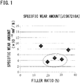
Fig. 1 is a diagram showing measurement results of a specific wear amount (DRY) corresponding to a filler ratio; -
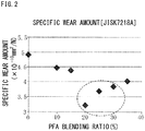
Fig. 2 is a diagram showing measurement results of a specific wear amount (DRY) corresponding to a blending ratio in a resin raw material; -
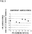
Fig. 3 is a diagram showing measurement results of counterpart aggressiveness corresponding to a blending ratio in a resin raw material; and -
Fig. 4 is a diagram showing measurement results of a sliding heat quantity caused by a difference in a shape of blended carbon fiber. - As a PTFE resin of the present invention, a common PTFE resin (melting point of 327°C) represented by "- (CF2-CF2)n-" can be used.
- As a modified PTFE resin of the present invention, a PTFE copolymer, in which the PTFE is modified with a copolymerizable monomer in an amount of 2 wt.% or less, is used. Examples of such a copolymerizable monomer include a perfluoroalkylether group, a fluoroalkyl group, or other side chain groups containing a fluoroalkyl group. The typical modified PTFE resin can be described as a copolymer of tetrafluoroethylene and an unsaturated compound selected from a group consisting of fluoroalkyl trifluoroethylene, ethylene, and propylene. The modified PTFE resin generally has more excellent compression resistance characteristics than a PTFE resin and thus can be preferably used. It is noted that a common PTFE resin and the modified PTFE resin may be used in combination.
- The PTFE resin and the modified PTFE resin have a number average molecular weight (Mn) of preferably about 500,000 to 10,000,000, further preferably 500,000 to 3,000,000. As the PTFE resin available on the market, Teflon (registered trademark) 7J (manufactured by Du Pont-Mitsui Fluorochemicals Co., Ltd.) may be used. Further, examples of the modified PTFE resin available on the market include Teflon (registered trademark) NXT70 (manufactured by Du Pont-Mitsui Fluorochemicals Co., Ltd.), Teflon (registered trademark) TG70J (manufactured by Du Pont-Mitsui Fluorochemicals Co., Ltd.), POLYFLON M111 and POLYFLON M112 (manufactured by Daikin Industries, Ltd.), and Hostaflon TFM1600 and Hostaflon TFM1700 (manufactured by Hoechst AG).
- A PFA copolymer resin blended in a PTFE resin raw material is a thermoplastic resin, which has a branch structure. Thus, it has good compatibility with a carbon fiber and exhibits a reinforcing effect to matrix. As a result, blending of the PFA copolymer resin improves wear resistance and reduces counterpart aggressiveness.
- In the present invention, the PFA copolymer resin having a lower MFR (melt flow rate) value (measured in accordance with ASTMD3307) (having a higher molecular weight) has better compatibility with the carbon fiber. The PFA copolymer resin has a MFR value of preferably less than 15g/10min, more preferably 4 to 8g/10min, particularly preferably 5 to 7g/10min. Specific examples of the PFA resin of the present invention available on the market include ACX21 (manufactured by Daikin Industries, Ltd.).
- A blending amount of the PFA copolymer resin is 18 to 30 wt.%, particularly preferably 20 to 25 wt.%, based on the total resin raw material (100 wt.%). When the blending amount is within this range, it is expected that a PTFE product having excellent sliding characteristics and low counterpart aggressiveness can be produced. When the blending amount of the PFA resin is less than 18 wt.%, there is no reinforcing effect to matrix obtained, while when it is more than 30 wt.%, wear resistance is deteriorated with an increase in sliding heat. It is noted that a preferable blending amount of the PFA copolymer resin in the total resin composition is 13 to 30 wt.%, preferably 15 to 23 wt.%, based on 100 wt.% of the total resin composition.
- The carbon fiber used in the present invention is a milled fiber obtained by grinding and shortening the carbon fiber. As a milled fiber, a pitch-based short fiber having an average fiber diameter of 5 to 20 µm and an average fiber length of 70 to 200 µm is preferable due to excellent dispersibility in the resin composition. Further, a high-temperature fired product (graphitized product) at a temperature of 2000°C or higher is more preferably used than a common fired product (carbonized product) at about 1000°C. As the carbon fiber, a pitch-based carbon fiber having an average fiber diameter of 5 to 20 µm and an average fiber length of about 70 to 200 µm is used. A pitch-based, highly graphitized carbon fiber is preferably used. The pitch-based carbon fiber is classified, according to a production raw material thereof, into an optically isotropic pitch and an optically anisotropic pitch (mesophase pitch), but the optically anisotropic pitch (mesophase pitch) has higher strength and elastic force after sizing and is thus preferable as the pitch-based carbon fiber of the present invention.
- Further, the carbon fiber in use is not formed in a straight shape, but in a curved/twisted shape having a curvature radius in a range of 50 to 1500 µm. When the curvature radius is less than 50 µm, the carbon fiber is broken in a compression molding process of the PTFE material and the proper fiber length cannot be maintained. When the curvature radius is more than 1500 µm, the carbon fiber is not sufficiently entangled with the PTFE and falling of the carbon fiber cannot be prevented. It is noted that the curvature radius is measured by taking secondary electron images using an electron microscope (JSM-5900LV manufactured by JEOL Ltd.) and analyzing the images using an image analysis software (Image-Pro Plus version7.0 manufactured by Media Cybernetics, Inc.).
- The curved/twisted carbon fiber selected in this manner is entangled with the PTFE in a curved/twisted part, thus the carbon fiber is hardly fallen off even when a bearing material is softened by sliding heat and reduces carbon fiber holding force.
- Specific examples of the curved/twisted carbon fiber available on the market include, as a carbon grade, S-2404N, S249K, and S-241 (manufactured by Osaka Gas Chemicals Co., Ltd.) and the like, and, as a highly graphitized carbon grade, SG-249 and SG-241 (manufactured by Osaka Gas Chemicals Co., Ltd.) and the like.
- It is noted that, as the carbon fiber, a PAN-based carbon fiber is commonly used other than the pitch-based carbon fiber, and a PAN-based carbon fiber formed in a curved/twisted shape having the above curvature radius of 50 to 1500 µm may be used in the same manner.
- A blending amount (filler ratio) of the curved/twisted carbon fiber is necessarily 18 to 35 wt.%, particularly preferably 20 to 30 wt.%, based on 100 wt.% of the total resin composition. The carbon fiber serves to protect the resin composition from sliding. Thus, when the blending amount is small, the soft resin tends to be exposed and become liable to wear, and when the blending amount is too large, the carbon fiber is hardly held by the resin.
- When the blending amount of the CF is less than 20 wt.%, wear resistance of the resin composition is reduced and when the blending amount of the CF is more than 35 wt.%, cracks are generated. Accordingly, both cases are not preferable.
- From the above, the blending amount of the carbon fiber in the total resin composition is 18 to 35 wt.%, preferably 20 to 30 wt.%, based on the total resin composition (100 wt.%), and the blending amount of the PFA resin in the total resin composition is 12 to 25 wt.%, preferably 14 to 20 wt.%, based on the total resin composition (100 wt.%). The remainder corresponds to a blending amount of the PTFE or the modified PTFE.
- It is noted that the remainder may include other inevitable materials.
- For mixing of the PTFE (modified PTFE) resin and the PFA resin and blending of the carbon fiber in the resin raw material, any blending methods can be adopted as long as three elements, two kinds of resin raw materials and the carbon fiber as a filler, are maintained in a good dispersion state. The blending is commonly performed using a mixer, such as a Henschel mixer and a super mixer. A blending order may be also appropriately set.
- As a processing method of the bearing material using the resin composition of the present invention, a common production method of bearing using a CF-containing PTFE (or modified PTFE) resin composition may be applied.
- Specifically, the production is performed using such a method in which the above blended product is molded under a pressure of about 70 to 80 MPa, subjected to a heat treatment at about 360 to 390°C for about 3 hours, and then subjected to a cutting process.
- The present invention will now be illustrated in greater detail with reference to Examples, but the present invention is not construed as being limited thereto.
- The other terms and concepts used in the present invention are based on meanings of the terms conventionally used in the art. Except for the techniques with apparent sources, the various techniques used to carry out the present invention can be easily and consistently performed by one of ordinary skill in the art with reference to published documents and the like. It is noted that "%" in Test Examples represents weight% without exception.
- As a PTFE resin raw material and a carbon fiber (CF), a modified PTFE (NXT70 manufactured by Du Pont-Mitsui Fluorochemicals Co., Ltd.) and a pitch-based, highly graphitized carbon fiber (CF) (SG-249 manufactured by Osaka Gas Chemicals Co., Ltd.) were used, respectively. The blending was performed in such a manner that a blending ratio (filler ratio) of the CF to the PTFE resin was 10%, 15%, 20%, 25%, 30%, 35%, and 40%. The blended product was mixed thoroughly using a Henschel mixer (type: FM20C/I), compression-molded at 60 to 70 MPa, and then fired in a firing furnace at 360 to 390°C for 3 hours to produce a disk-shaped test piece (outer diameter of 40 mm, thickness of 2 mm).
- A sliding characteristics (dynamic friction coefficient) test was performed by measuring a specific wear amount using a ring-on-disk method according to JISK7218A standards. As a counterpart material (ring material), S45C (carbon steel having carbon content of 0.45%) (outer diameter of 25.6 mm, inner diameter of 20 mm, height of 2 mm) was used. Then, the disk-shaped test piece was rotated at a speed of 0.5 m/s for 24 hours under a pressure of 0.8 MPa in a dry condition.
- As a result, it was found that when the blending ratio (filler ratio) of the CF was about 18 to 33%, particularly in a range of 20 to 30%, the test piece had a low specific wear amount and exhibited excellent sliding characteristics (
Fig. 1 ). - Based on the result of Test Example 1, the filler ratio of the CF to the PTFE resin was fixed at 25%, and the sliding characteristics test was performed as in Test Example 1 by measuring a specific wear amount while changing a blending ratio of modified PTFE and a PFA in the PTFE resin raw material.
- Specifically, 25% of the pitch-based, highly graphitized CF, which was the same as in Test Example 1, was blended in 75% of the PTFE resin raw material. Of 75% of the PTFE resin raw material, a PFA (ACX21 manufactured by Daikin Industries, Ltd.) was blended in a modified PTFE (NXT70) at a blending ratio of 0%, 10%, 15%, 20%, 25%, 30%, and 35% based on the total resin raw material. Then, a disk-shaped test piece was produced by the same method as in Test Example 1.
- Subsequently, a specific wear amount to the counterpart material S45C was measured in a dry condition using the same ring-on-disk method (JISK7218A standards) as in Test Example 1.
- As a result, it was found that when the blending ratio of the PFA was about 18 to 35%, particularly in a range of 20 to 30%, based on the total resin raw material, the test piece had a low specific wear amount and exhibited excellent sliding characteristics (
Fig. 2 ). - Similar to Test Example 2, the filler ratio of the CF was fixed at 25%, and a counterpart aggressiveness test was performed while changing the blending ratio of the modified PTFE and the PFA in the PTFE raw material.
- Specifically, similar to Test Example 2, the blending ratio of the PFA in the PTFE resin raw material, which accounted for 75% of the total material, is set to 0%, 10%, 15%, 20%, 25%, and 30% based on the total resin raw material. Then, a disk-shaped test piece was produced by the same method as in Test Example 1.
- Subsequently, a counterpart aggressiveness test was performed by measuring a change rate (%) of Rz (ten-point average roughness) of the counterpart material in a dry condition for each test piece having a different PFA blending ratio according to JIS0601-1976 standards related to surface roughness.
- As the counterpart material, the same carbon steel S45C as in Test Examples 1 and 2 was used. A surface roughness of the counterpart material before test was measured by a stylus-type surface roughness tester according to JIS0601-1976 to calculate Rz. It was RZ1.5 µm.
- In the test, as in Test Examples 1 and 2, each disk-shaped test piece was rotated at a speed of 0.5 m/s for 24 hours under a pressure of 0.8 MPa in a dry condition to measure a RZ value. This RZ value was compared to the RZ1.5 µm before test to calculate a change rate (%) of counterpart roughness.
- In this calculation, the change rate (%) of counterpart roughness is given by a minus notation, and, as the value approaches zero, the test sample is evaluated as less aggressiveness.
- As a result, it was found that the test samples having the PFA blending ratio of about 18 to 30%, particularly 20 to 25%, have low aggressiveness (
Fig. 3 ). - By combining the results in Test Example 2 and Test Example 3, it is expected that a PTFE product having excellent sliding characteristics and low counterpart aggressiveness can be produced by setting the blending ratio of the PFA in the total PTFE raw material to about 18 to 30%, particularly 20 to 25%. It is required, from Text Example 1, that an optimum filler ratio of the CF is 18 to 33%, particularly 20 to 30%, thus, the blending ratio of the PFA in the total PTFE product having excellent sliding characteristics and low counterpart aggressiveness is 12 to 25%, preferably 14 to 20%. The PTFE is the remainder of the PFA and the CF, thus their ratio is PFA:CF:PTFE = 12 to 25:18 to 33:remainder, preferably PFA:CF:PTFE = 14 to 20:20 to 30:remainder.
- In the present test, in order to select the CF having a lower sliding heat property for blending in the PTFE resin raw material, the filler ratio of the CF to 70% of the PTFE resin was fixed at 30% while changing a type of the CF to be blended. Then, a disk-shaped test piece was produced by the same method as in Test Example 1.
- In this test, as the PTFE resin, a PTFE (7J manufactured by Du Pont-Mitsui Fluorochemicals Co., Ltd.) was used and, as the carbon fiber (CF) to be blended, the following pitch-based carbon fibers were used: a straight CF (M2007SA manufactured by KUREHA Corp.); a twisted CF in a carbon grade (S-2404N, S249K, and S-241 manufactured by Osaka Gas Chemicals Co., Ltd.); and a twisted CF in a highly graphitized carbon grade (SG-249 and SG-241 manufactured by Osaka Gas Chemicals Co., Ltd.).
- In a sliding heat test, as in Test Examples 1 to 3, a disk-shaped test piece was rotated at a speed of 0.5 m/s for 24 hours under a pressure of 0.8 MPa in a dry condition using the carbon steel S45C as a counterpart material to measure a temperature near a sliding part (
Fig. 4 ). It is noted that the sliding test was performed after adjusting a temperature near a sliding part to a room temperature (25°C). - As a result, it was found that, among the pitch-based carbon fibers (CFs), the straight carbon fiber caused the temperature near a sliding part to go up to about 150°C and was unable to be used due to high sliding heat, while the twisted CFs could suppress sliding heat to be less than 100°C and be sufficiently used. In particular, it was found that using the highly graphitized CF caused low sliding heat and was thus more preferable.
- Fifty five pts.wt of a modified PTFE (NXT70 manufactured by Du Pont-Mitsui Fluorochemicals Co., Ltd.), 20 pts.wt of a PFA (ACX21 manufactured by Daikin Industries, Ltd.), and 25 pts.wt of a pitch-based, curved/twisted carbon fiber (S-249 manufactured by Osaka Gas Chemicals Co., Ltd.; average fiber diameter of 13 µm, average fiber length of 90 µm) were mixed using a Henschel mixer (type: FM20C/I), compression-molded at 60 to 70 MPa by pressing and the like, and then fired in a firing furnace at 360 to 390°C for 3 hours.
- Subsequently, the fired product was cut to produce an NZ-7280 type bearing for test. The bearing was subjected to a functional characteristic evaluation test for bearing by performing a bearing operation for 168 hours and evaluated according to the following product evaluation criteria.
- A wear amount of a sliding surface of the bearing after test was measured according to ISK7214K standards and evaluated by the following criteria: ⊚ if the specific wear amount is less than 2.0 × 10⁻¹² mm2/N, ○ if it is 2.0 to 4.0 × 10⁻¹² mm2/N, and × if it is more than 4.0 × 10⁻¹² mm2/N.
- Cracking in the test product was visually inspected after the bearing operation and the "presence of cracking" was confirmed if a crack was observed.
- These evaluation results are shown in the following (Table 1).
- A bearing was produced and used as in Example 1 except that the amounts of the modified PTFE, the PFA, and the pitch-based, curved/twisted carbon fiber were changed to 65 pts.wt, 20 pts.wt, and 15 pts.wt, respectively.
- These evaluation results are shown in the following (Table 1).
- A bearing was produced and used as in Example 1 except that the amounts of the modified PTFE, the PFA, and the pitch-based, curved/twisted carbon fiber were changed to 60 pts.wt, 15 pts.wt, and 25 pts.wt, respectively.
- These evaluation results are shown in the following (Table 1).
- A bearing was produced and used as in Example 1 except that the amounts of the modified PTFE, the PFA, and the pitch-based, curved/twisted carbon fiber were changed to 45 pts.wt, 20 pts.wt, and 35 pts.wt, respectively.
- These evaluation results are shown in the following (Table 1).
- A bearing was produced and used as in Example 1 except that the amounts of the modified PTFE, the PFA, and the pitch-based, curved/twisted carbon fiber were changed to 45 pts.wt, 30 pts.wt, and 25 pts.wt, respectively.
- These evaluation results are shown in the following (Table 1).
- A bearing was produced and used as in Example 1 except that the amounts of the modified PTFE and the pitch-based, curved/twisted carbon fiber were changed to 75 pts.wt and 25 pts.wt, respectively, without blending the PFA.
- These evaluation results are shown in the following (Table 1).
[Table 1] Blending ratio Examples Comparative Examples 1 2 3 1 2 3 PTFE (pts.wt) 55 65 60 45 45 75 PFA (pts.wt) 20 20 15 20 30 - CF (pts.wt) 25 15 25 35 25 25 Evaluation criteria Wear resistance ⊚ ○ ○ ⊚ × × Cracking of product No No No Yes No No - From the above results, it was confirmed that, when the blending ration of the CF exceeded 35 pts.wt in the total composition (100 pts.wt), cracking of the product occurred, which was not preferable, further when the blending ration of the PFA resin exceeded 30 pts.wt, wear resistance was deteriorated.
Claims (8)
- A water lubrication type bearing material comprising:12 wt.% to 25 wt.% of a tetrafluoroethylene-perfluoroalkyl vinyl ether copolymer resin (PFA resin);18 wt.% to 33 wt.% of a carbon fiber; anda remainder including a polytetrafluoroethylene (PTFE) resin and/or a modified PTFE resin,wherein the carbon fiber is a curved/twisted carbon fiber.
- The water lubrication type bearing material according to claim 1, wherein the carbon fiber is a pitch-based carbon fiber.
- The water lubrication type bearing material according to claim 1 or 2, wherein a curvature radius of the curved/twisted carbon fiber is in a range of 50 to 1500 µm.
- The water lubrication type bearing material according to any one of claims 1 to 3, wherein a length of the carbon fiber is 70 to 200 µm.
- The water lubrication type bearing material according to any one of claims 1 to 4, being used as a bearing for water circulation type seal system of ship.
- The water lubrication type bearing material according to any one of claims 1 to 5, wherein the modified PTFE is a copolymer of tetrafluoroethylene and an unsaturated compound selected from a group consisting of fluoroalkyl trifluoroethylene, ethylene, and propylene.
- The water lubrication type bearing material according to any one of claims 1 to 6, wherein the PFA has a melt flow rate value (MFR) of less than 15g/10min in accordance with ASTMD3307.
- The water lubrication type bearing material according to any one of claims 1 to 7, being arranged inside a metallic member.
Applications Claiming Priority (2)
| Application Number | Priority Date | Filing Date | Title |
|---|---|---|---|
| JP2015007305 | 2015-01-17 | ||
| PCT/JP2016/050621 WO2016114244A1 (en) | 2015-01-17 | 2016-01-12 | Water-lubricated bearing material |
Publications (3)
| Publication Number | Publication Date |
|---|---|
| EP3246583A1 EP3246583A1 (en) | 2017-11-22 |
| EP3246583A4 EP3246583A4 (en) | 2018-09-05 |
| EP3246583B1 true EP3246583B1 (en) | 2020-07-01 |
Family
ID=56405790
Family Applications (1)
| Application Number | Title | Priority Date | Filing Date |
|---|---|---|---|
| EP16737315.8A Active EP3246583B1 (en) | 2015-01-17 | 2016-01-12 | Water-lubricated bearing material |
Country Status (7)
| Country | Link |
|---|---|
| US (1) | US10196576B2 (en) |
| EP (1) | EP3246583B1 (en) |
| JP (1) | JP6606513B2 (en) |
| KR (1) | KR102418834B1 (en) |
| CN (1) | CN107110212B (en) |
| TW (1) | TW201627584A (en) |
| WO (1) | WO2016114244A1 (en) |
Families Citing this family (11)
| Publication number | Priority date | Publication date | Assignee | Title |
|---|---|---|---|---|
| EP2998354A4 (en) * | 2013-05-13 | 2016-12-07 | Eagle Ind Co Ltd | Ptfe resin composition |
| CN108612762B (en) * | 2018-04-28 | 2020-05-05 | 天津大学 | Self-lubricating sliding bearing with full-life surface texture |
| WO2019225435A1 (en) | 2018-05-22 | 2019-11-28 | ダイキン工業株式会社 | Resin composition |
| JP6750645B2 (en) * | 2018-05-22 | 2020-09-02 | ダイキン工業株式会社 | Polytetrafluoroethylene composition |
| JP7136734B2 (en) * | 2019-03-28 | 2022-09-13 | 大同メタル工業株式会社 | sliding member |
| CN110951519B (en) * | 2019-12-06 | 2022-09-30 | 平湖市凯丰机械制造有限公司 | Water-lubricated solid lubricating column and manufacturing method thereof |
| CN111378333B (en) * | 2020-05-17 | 2022-02-15 | 广西大学 | Preparation method of composite modified polytetrafluoroethylene coating |
| JP7343940B2 (en) | 2020-06-25 | 2023-09-13 | 株式会社ミカサ | Bearings for ship propulsion shafts |
| JP7539280B2 (en) * | 2020-09-18 | 2024-08-23 | 三井・ケマーズ フロロプロダクツ株式会社 | Compression molding composition, its manufacturing method, and molded article |
| CN114382633A (en) * | 2021-12-31 | 2022-04-22 | 杭州诚德发电设备有限公司 | Water-lubricated water-guide bearing device and environment-friendly water-lubricated rust remover applied to water-lubricated water-guide bearing device |
| CN118613534A (en) * | 2022-02-28 | 2024-09-06 | 东丽株式会社 | Molded base material, porous body, sheath-core structure, and structural member |
Family Cites Families (31)
| Publication number | Priority date | Publication date | Assignee | Title |
|---|---|---|---|---|
| JPS59103022A (en) * | 1982-12-03 | 1984-06-14 | Daido Metal Kogyo Kk | Bearing material having superior wearing resistance |
| JPS60258297A (en) * | 1984-06-05 | 1985-12-20 | Daido Metal Kogyo Kk | Sliding material having excellent abrasion resistance |
| JP2511352B2 (en) | 1991-11-13 | 1996-06-26 | 西川ゴム工業株式会社 | Manufacturing method of water-lubricated segment type bearing strip for large ships |
| JP2948393B2 (en) * | 1991-12-10 | 1999-09-13 | 日東電工株式会社 | Sliding material and composition usable for molding thereof |
| JPH0823033B2 (en) * | 1992-01-17 | 1996-03-06 | 大同メタル工業株式会社 | Composite sliding member |
| JPH07268126A (en) * | 1994-03-31 | 1995-10-17 | Ntn Corp | Lubricating resin composition |
| JP3213193B2 (en) * | 1995-02-01 | 2001-10-02 | 大同メタル工業株式会社 | Sliding composition and sliding member |
| JP3472050B2 (en) | 1995-10-02 | 2003-12-02 | 大同メタル工業株式会社 | Sliding member for wet type thrust bearing |
| JP3668748B2 (en) * | 1995-11-08 | 2005-07-06 | ダイキン工業株式会社 | Non-adhesive molding material for sliding parts, separation claw and paper discharge roller |
| US5961218A (en) * | 1996-02-20 | 1999-10-05 | Ebara Corporation | Water lubricated machine component having contacting sliding surfaces |
| JP3045472B2 (en) * | 1996-05-31 | 2000-05-29 | 大同メタル工業株式会社 | Sliding member for thrust bearing |
| JP3149377B2 (en) * | 1997-01-22 | 2001-03-26 | 大同メタル工業株式会社 | Sliding member for wet radial bearing |
| JP3660123B2 (en) * | 1997-06-30 | 2005-06-15 | Ntn株式会社 | Pressure-resistant sliding tetrafluoroethylene resin composition |
| JP2000055054A (en) | 1998-08-11 | 2000-02-22 | Ntn Corp | Combined layer bearing |
| JP2001124070A (en) | 1999-10-21 | 2001-05-08 | Hitachi Ltd | Water lubricated bearing device |
| JP2002327750A (en) | 2001-04-27 | 2002-11-15 | Ntn Corp | Multi-layered bearing |
| GB2382556B (en) * | 2001-11-30 | 2005-03-09 | Railko Ltd | Propeller shaft bearing |
| US7703983B2 (en) * | 2004-06-10 | 2010-04-27 | Ntn Corporation | Sliding material and sliding bearing |
| EP1612021B1 (en) * | 2004-06-29 | 2009-09-02 | Asahi Glass Company Ltd. | Release film for encapsulation of semiconductor chip |
| JP4897316B2 (en) | 2006-03-15 | 2012-03-14 | 株式会社日立エンジニアリング・アンド・サービス | Water lubrication pad type bearing device and water wheel |
| JP4597152B2 (en) | 2007-02-19 | 2010-12-15 | 株式会社日立エンジニアリング・アンド・サービス | Pad type bearing device and horizontal axis turbine |
| CN100504091C (en) * | 2007-09-11 | 2009-06-24 | 嘉兴中达自润轴承工业有限公司 | Polymer self-lubricating thin layer composite axle sleeve and its preparation method |
| JP5021576B2 (en) | 2008-06-30 | 2012-09-12 | 日立三菱水力株式会社 | Pad type bearing device and horizontal axis turbine |
| US8247486B2 (en) * | 2008-07-01 | 2012-08-21 | E.I. Du Pont De Nemours And Company | Creep resistant fluoropolymer |
| JP5342883B2 (en) | 2009-01-07 | 2013-11-13 | Ntn株式会社 | Double layer bearing |
| JP4932884B2 (en) * | 2009-05-01 | 2012-05-16 | アクロス株式会社 | Coating composition for sliding member |
| JP4527183B2 (en) | 2009-07-13 | 2010-08-18 | 株式会社日立製作所 | Water lubrication segment type bearing device and water turbine |
| JP2013007006A (en) | 2011-06-27 | 2013-01-10 | Nok Corp | Water-lubricated bearing material |
| JP2014109292A (en) * | 2012-11-30 | 2014-06-12 | Sumitomo Denko Shoketsu Gokin Kk | Slide member |
| EP2998354A4 (en) * | 2013-05-13 | 2016-12-07 | Eagle Ind Co Ltd | Ptfe resin composition |
| KR20150039548A (en) * | 2013-10-02 | 2015-04-10 | 가부시키가이샤 시마노 | Slide member, bicycle component using slide member, fishing tackle component using slide member, and method of manufacturing slide member |
-
2016
- 2016-01-12 WO PCT/JP2016/050621 patent/WO2016114244A1/en active Application Filing
- 2016-01-12 JP JP2016569349A patent/JP6606513B2/en active Active
- 2016-01-12 EP EP16737315.8A patent/EP3246583B1/en active Active
- 2016-01-12 TW TW105100728A patent/TW201627584A/en unknown
- 2016-01-12 US US15/542,403 patent/US10196576B2/en active Active
- 2016-01-12 CN CN201680004881.1A patent/CN107110212B/en active Active
- 2016-01-12 KR KR1020177019127A patent/KR102418834B1/en active IP Right Grant
Non-Patent Citations (1)
| Title |
|---|
| None * |
Also Published As
| Publication number | Publication date |
|---|---|
| KR20170106323A (en) | 2017-09-20 |
| EP3246583A1 (en) | 2017-11-22 |
| CN107110212B (en) | 2019-09-10 |
| WO2016114244A1 (en) | 2016-07-21 |
| JP6606513B2 (en) | 2019-11-13 |
| KR102418834B1 (en) | 2022-07-11 |
| US20170362526A1 (en) | 2017-12-21 |
| US10196576B2 (en) | 2019-02-05 |
| CN107110212A (en) | 2017-08-29 |
| TW201627584A (en) | 2016-08-01 |
| EP3246583A4 (en) | 2018-09-05 |
| JPWO2016114244A1 (en) | 2017-10-26 |
Similar Documents
| Publication | Publication Date | Title |
|---|---|---|
| EP3246583B1 (en) | Water-lubricated bearing material | |
| KR101835911B1 (en) | Composite slide bearing | |
| JP5568184B2 (en) | Seal ring | |
| JP5702385B2 (en) | Resin composition and molded product | |
| US20100290726A1 (en) | Plain bearing | |
| US20100300726A1 (en) | Polymer compound as well as structural parts produced using the compound | |
| JP2006194397A (en) | Multiple layer sliding member | |
| WO2013088964A1 (en) | Resin composition and molded article | |
| WO2015119231A1 (en) | Plain bearing | |
| JPH07268126A (en) | Lubricating resin composition | |
| JPS58160353A (en) | Resin composition | |
| JPH03292366A (en) | Wear-resistant resin composition | |
| CN112154188B (en) | Resin composition | |
| JP2018109149A (en) | Polytetrafluoroethylene composition | |
| JP2014142070A (en) | Compound slide bearing | |
| JP2014134290A (en) | Method of manufacturing composite slide bearing | |
| WO2004094528A1 (en) | Polytetrafluoroethylene resin composition | |
| WO2023167117A1 (en) | Resin composition for sliding, and sliding member | |
| JP2010156398A (en) | Sliding material | |
| JP2005281446A (en) | Tetrafluoroethylene resin composition and sliding member produced by using the same | |
| JP4321290B2 (en) | Tetrafluoroethylene-ethylene copolymer resin composition | |
| JP6199196B2 (en) | Plain bearing | |
| JP2023153091A (en) | resin composition | |
| JP2011241308A (en) | Modified polytetrafluoroethylene composition | |
| Aderikha et al. | New antifriction materials based on polytetrafluoroethylene and polyoxadiazole fibres |
Legal Events
| Date | Code | Title | Description |
|---|---|---|---|
| STAA | Information on the status of an ep patent application or granted ep patent |
Free format text: STATUS: THE INTERNATIONAL PUBLICATION HAS BEEN MADE |
|
| PUAI | Public reference made under article 153(3) epc to a published international application that has entered the european phase |
Free format text: ORIGINAL CODE: 0009012 |
|
| STAA | Information on the status of an ep patent application or granted ep patent |
Free format text: STATUS: REQUEST FOR EXAMINATION WAS MADE |
|
| 17P | Request for examination filed |
Effective date: 20170707 |
|
| AK | Designated contracting states |
Kind code of ref document: A1 Designated state(s): AL AT BE BG CH CY CZ DE DK EE ES FI FR GB GR HR HU IE IS IT LI LT LU LV MC MK MT NL NO PL PT RO RS SE SI SK SM TR |
|
| AX | Request for extension of the european patent |
Extension state: BA ME |
|
| DAV | Request for validation of the european patent (deleted) | ||
| DAX | Request for extension of the european patent (deleted) | ||
| A4 | Supplementary search report drawn up and despatched |
Effective date: 20180806 |
|
| RIC1 | Information provided on ipc code assigned before grant |
Ipc: B63H 23/34 20060101ALI20180731BHEP Ipc: C08L 27/18 20060101ALI20180731BHEP Ipc: C08K 7/06 20060101ALI20180731BHEP Ipc: F16C 17/14 20060101ALI20180731BHEP Ipc: F16C 33/20 20060101AFI20180731BHEP |
|
| GRAP | Despatch of communication of intention to grant a patent |
Free format text: ORIGINAL CODE: EPIDOSNIGR1 |
|
| STAA | Information on the status of an ep patent application or granted ep patent |
Free format text: STATUS: GRANT OF PATENT IS INTENDED |
|
| INTG | Intention to grant announced |
Effective date: 20200414 |
|
| GRAS | Grant fee paid |
Free format text: ORIGINAL CODE: EPIDOSNIGR3 |
|
| GRAA | (expected) grant |
Free format text: ORIGINAL CODE: 0009210 |
|
| STAA | Information on the status of an ep patent application or granted ep patent |
Free format text: STATUS: THE PATENT HAS BEEN GRANTED |
|
| AK | Designated contracting states |
Kind code of ref document: B1 Designated state(s): AL AT BE BG CH CY CZ DE DK EE ES FI FR GB GR HR HU IE IS IT LI LT LU LV MC MK MT NL NO PL PT RO RS SE SI SK SM TR |
|
| REG | Reference to a national code |
Ref country code: AT Ref legal event code: REF Ref document number: 1286467 Country of ref document: AT Kind code of ref document: T Effective date: 20200715 Ref country code: CH Ref legal event code: EP |
|
| REG | Reference to a national code |
Ref country code: IE Ref legal event code: FG4D |
|
| REG | Reference to a national code |
Ref country code: DE Ref legal event code: R096 Ref document number: 602016039122 Country of ref document: DE |
|
| REG | Reference to a national code |
Ref country code: LT Ref legal event code: MG4D |
|
| PG25 | Lapsed in a contracting state [announced via postgrant information from national office to epo] |
Ref country code: BG Free format text: LAPSE BECAUSE OF FAILURE TO SUBMIT A TRANSLATION OF THE DESCRIPTION OR TO PAY THE FEE WITHIN THE PRESCRIBED TIME-LIMIT Effective date: 20201001 |
|
| REG | Reference to a national code |
Ref country code: NL Ref legal event code: MP Effective date: 20200701 |
|
| REG | Reference to a national code |
Ref country code: AT Ref legal event code: MK05 Ref document number: 1286467 Country of ref document: AT Kind code of ref document: T Effective date: 20200701 |
|
| PG25 | Lapsed in a contracting state [announced via postgrant information from national office to epo] |
Ref country code: SE Free format text: LAPSE BECAUSE OF FAILURE TO SUBMIT A TRANSLATION OF THE DESCRIPTION OR TO PAY THE FEE WITHIN THE PRESCRIBED TIME-LIMIT Effective date: 20200701 Ref country code: HR Free format text: LAPSE BECAUSE OF FAILURE TO SUBMIT A TRANSLATION OF THE DESCRIPTION OR TO PAY THE FEE WITHIN THE PRESCRIBED TIME-LIMIT Effective date: 20200701 Ref country code: AT Free format text: LAPSE BECAUSE OF FAILURE TO SUBMIT A TRANSLATION OF THE DESCRIPTION OR TO PAY THE FEE WITHIN THE PRESCRIBED TIME-LIMIT Effective date: 20200701 Ref country code: ES Free format text: LAPSE BECAUSE OF FAILURE TO SUBMIT A TRANSLATION OF THE DESCRIPTION OR TO PAY THE FEE WITHIN THE PRESCRIBED TIME-LIMIT Effective date: 20200701 Ref country code: GR Free format text: LAPSE BECAUSE OF FAILURE TO SUBMIT A TRANSLATION OF THE DESCRIPTION OR TO PAY THE FEE WITHIN THE PRESCRIBED TIME-LIMIT Effective date: 20201002 Ref country code: NO Free format text: LAPSE BECAUSE OF FAILURE TO SUBMIT A TRANSLATION OF THE DESCRIPTION OR TO PAY THE FEE WITHIN THE PRESCRIBED TIME-LIMIT Effective date: 20201001 Ref country code: PT Free format text: LAPSE BECAUSE OF FAILURE TO SUBMIT A TRANSLATION OF THE DESCRIPTION OR TO PAY THE FEE WITHIN THE PRESCRIBED TIME-LIMIT Effective date: 20201102 Ref country code: CZ Free format text: LAPSE BECAUSE OF FAILURE TO SUBMIT A TRANSLATION OF THE DESCRIPTION OR TO PAY THE FEE WITHIN THE PRESCRIBED TIME-LIMIT Effective date: 20200701 Ref country code: LT Free format text: LAPSE BECAUSE OF FAILURE TO SUBMIT A TRANSLATION OF THE DESCRIPTION OR TO PAY THE FEE WITHIN THE PRESCRIBED TIME-LIMIT Effective date: 20200701 Ref country code: FI Free format text: LAPSE BECAUSE OF FAILURE TO SUBMIT A TRANSLATION OF THE DESCRIPTION OR TO PAY THE FEE WITHIN THE PRESCRIBED TIME-LIMIT Effective date: 20200701 |
|
| PG25 | Lapsed in a contracting state [announced via postgrant information from national office to epo] |
Ref country code: IS Free format text: LAPSE BECAUSE OF FAILURE TO SUBMIT A TRANSLATION OF THE DESCRIPTION OR TO PAY THE FEE WITHIN THE PRESCRIBED TIME-LIMIT Effective date: 20201101 Ref country code: LV Free format text: LAPSE BECAUSE OF FAILURE TO SUBMIT A TRANSLATION OF THE DESCRIPTION OR TO PAY THE FEE WITHIN THE PRESCRIBED TIME-LIMIT Effective date: 20200701 Ref country code: RS Free format text: LAPSE BECAUSE OF FAILURE TO SUBMIT A TRANSLATION OF THE DESCRIPTION OR TO PAY THE FEE WITHIN THE PRESCRIBED TIME-LIMIT Effective date: 20200701 Ref country code: PL Free format text: LAPSE BECAUSE OF FAILURE TO SUBMIT A TRANSLATION OF THE DESCRIPTION OR TO PAY THE FEE WITHIN THE PRESCRIBED TIME-LIMIT Effective date: 20200701 |
|
| PG25 | Lapsed in a contracting state [announced via postgrant information from national office to epo] |
Ref country code: NL Free format text: LAPSE BECAUSE OF FAILURE TO SUBMIT A TRANSLATION OF THE DESCRIPTION OR TO PAY THE FEE WITHIN THE PRESCRIBED TIME-LIMIT Effective date: 20200701 |
|
| REG | Reference to a national code |
Ref country code: DE Ref legal event code: R097 Ref document number: 602016039122 Country of ref document: DE |
|
| PG25 | Lapsed in a contracting state [announced via postgrant information from national office to epo] |
Ref country code: SM Free format text: LAPSE BECAUSE OF FAILURE TO SUBMIT A TRANSLATION OF THE DESCRIPTION OR TO PAY THE FEE WITHIN THE PRESCRIBED TIME-LIMIT Effective date: 20200701 Ref country code: RO Free format text: LAPSE BECAUSE OF FAILURE TO SUBMIT A TRANSLATION OF THE DESCRIPTION OR TO PAY THE FEE WITHIN THE PRESCRIBED TIME-LIMIT Effective date: 20200701 Ref country code: DK Free format text: LAPSE BECAUSE OF FAILURE TO SUBMIT A TRANSLATION OF THE DESCRIPTION OR TO PAY THE FEE WITHIN THE PRESCRIBED TIME-LIMIT Effective date: 20200701 Ref country code: EE Free format text: LAPSE BECAUSE OF FAILURE TO SUBMIT A TRANSLATION OF THE DESCRIPTION OR TO PAY THE FEE WITHIN THE PRESCRIBED TIME-LIMIT Effective date: 20200701 Ref country code: IT Free format text: LAPSE BECAUSE OF FAILURE TO SUBMIT A TRANSLATION OF THE DESCRIPTION OR TO PAY THE FEE WITHIN THE PRESCRIBED TIME-LIMIT Effective date: 20200701 |
|
| PLBE | No opposition filed within time limit |
Free format text: ORIGINAL CODE: 0009261 |
|
| STAA | Information on the status of an ep patent application or granted ep patent |
Free format text: STATUS: NO OPPOSITION FILED WITHIN TIME LIMIT |
|
| PG25 | Lapsed in a contracting state [announced via postgrant information from national office to epo] |
Ref country code: AL Free format text: LAPSE BECAUSE OF FAILURE TO SUBMIT A TRANSLATION OF THE DESCRIPTION OR TO PAY THE FEE WITHIN THE PRESCRIBED TIME-LIMIT Effective date: 20200701 |
|
| 26N | No opposition filed |
Effective date: 20210406 |
|
| PG25 | Lapsed in a contracting state [announced via postgrant information from national office to epo] |
Ref country code: SK Free format text: LAPSE BECAUSE OF FAILURE TO SUBMIT A TRANSLATION OF THE DESCRIPTION OR TO PAY THE FEE WITHIN THE PRESCRIBED TIME-LIMIT Effective date: 20200701 |
|
| PG25 | Lapsed in a contracting state [announced via postgrant information from national office to epo] |
Ref country code: MC Free format text: LAPSE BECAUSE OF FAILURE TO SUBMIT A TRANSLATION OF THE DESCRIPTION OR TO PAY THE FEE WITHIN THE PRESCRIBED TIME-LIMIT Effective date: 20200701 Ref country code: SI Free format text: LAPSE BECAUSE OF FAILURE TO SUBMIT A TRANSLATION OF THE DESCRIPTION OR TO PAY THE FEE WITHIN THE PRESCRIBED TIME-LIMIT Effective date: 20200701 |
|
| REG | Reference to a national code |
Ref country code: CH Ref legal event code: PL |
|
| GBPC | Gb: european patent ceased through non-payment of renewal fee |
Effective date: 20210112 |
|
| PG25 | Lapsed in a contracting state [announced via postgrant information from national office to epo] |
Ref country code: LU Free format text: LAPSE BECAUSE OF NON-PAYMENT OF DUE FEES Effective date: 20210112 |
|
| REG | Reference to a national code |
Ref country code: BE Ref legal event code: MM Effective date: 20210131 |
|
| PG25 | Lapsed in a contracting state [announced via postgrant information from national office to epo] |
Ref country code: FR Free format text: LAPSE BECAUSE OF NON-PAYMENT OF DUE FEES Effective date: 20210131 |
|
| PG25 | Lapsed in a contracting state [announced via postgrant information from national office to epo] |
Ref country code: CH Free format text: LAPSE BECAUSE OF NON-PAYMENT OF DUE FEES Effective date: 20210131 Ref country code: GB Free format text: LAPSE BECAUSE OF NON-PAYMENT OF DUE FEES Effective date: 20210112 Ref country code: LI Free format text: LAPSE BECAUSE OF NON-PAYMENT OF DUE FEES Effective date: 20210131 |
|
| PG25 | Lapsed in a contracting state [announced via postgrant information from national office to epo] |
Ref country code: IE Free format text: LAPSE BECAUSE OF NON-PAYMENT OF DUE FEES Effective date: 20210112 |
|
| PG25 | Lapsed in a contracting state [announced via postgrant information from national office to epo] |
Ref country code: IS Free format text: LAPSE BECAUSE OF FAILURE TO SUBMIT A TRANSLATION OF THE DESCRIPTION OR TO PAY THE FEE WITHIN THE PRESCRIBED TIME-LIMIT Effective date: 20201101 |
|
| PG25 | Lapsed in a contracting state [announced via postgrant information from national office to epo] |
Ref country code: BE Free format text: LAPSE BECAUSE OF NON-PAYMENT OF DUE FEES Effective date: 20210131 |
|
| PG25 | Lapsed in a contracting state [announced via postgrant information from national office to epo] |
Ref country code: HU Free format text: LAPSE BECAUSE OF FAILURE TO SUBMIT A TRANSLATION OF THE DESCRIPTION OR TO PAY THE FEE WITHIN THE PRESCRIBED TIME-LIMIT; INVALID AB INITIO Effective date: 20160112 |
|
| PG25 | Lapsed in a contracting state [announced via postgrant information from national office to epo] |
Ref country code: CY Free format text: LAPSE BECAUSE OF FAILURE TO SUBMIT A TRANSLATION OF THE DESCRIPTION OR TO PAY THE FEE WITHIN THE PRESCRIBED TIME-LIMIT Effective date: 20200701 |
|
| PG25 | Lapsed in a contracting state [announced via postgrant information from national office to epo] |
Ref country code: MK Free format text: LAPSE BECAUSE OF FAILURE TO SUBMIT A TRANSLATION OF THE DESCRIPTION OR TO PAY THE FEE WITHIN THE PRESCRIBED TIME-LIMIT Effective date: 20200701 |
|
| PGFP | Annual fee paid to national office [announced via postgrant information from national office to epo] |
Ref country code: DE Payment date: 20231128 Year of fee payment: 9 |