EP3246518A1 - Leitschaufelkranz, zugehörige baugruppe und strömungsmaschine - Google Patents
Leitschaufelkranz, zugehörige baugruppe und strömungsmaschine Download PDFInfo
- Publication number
- EP3246518A1 EP3246518A1 EP17154291.3A EP17154291A EP3246518A1 EP 3246518 A1 EP3246518 A1 EP 3246518A1 EP 17154291 A EP17154291 A EP 17154291A EP 3246518 A1 EP3246518 A1 EP 3246518A1
- Authority
- EP
- European Patent Office
- Prior art keywords
- inner ring
- vane
- blade
- ring
- turbomachine
- Prior art date
- Legal status (The legal status is an assumption and is not a legal conclusion. Google has not performed a legal analysis and makes no representation as to the accuracy of the status listed.)
- Granted
Links
Images

Classifications
-
- F—MECHANICAL ENGINEERING; LIGHTING; HEATING; WEAPONS; BLASTING
- F01—MACHINES OR ENGINES IN GENERAL; ENGINE PLANTS IN GENERAL; STEAM ENGINES
- F01D—NON-POSITIVE DISPLACEMENT MACHINES OR ENGINES, e.g. STEAM TURBINES
- F01D9/00—Stators
- F01D9/02—Nozzles; Nozzle boxes; Stator blades; Guide conduits, e.g. individual nozzles
- F01D9/04—Nozzles; Nozzle boxes; Stator blades; Guide conduits, e.g. individual nozzles forming ring or sector
- F01D9/041—Nozzles; Nozzle boxes; Stator blades; Guide conduits, e.g. individual nozzles forming ring or sector using blades
-
- F—MECHANICAL ENGINEERING; LIGHTING; HEATING; WEAPONS; BLASTING
- F04—POSITIVE - DISPLACEMENT MACHINES FOR LIQUIDS; PUMPS FOR LIQUIDS OR ELASTIC FLUIDS
- F04D—NON-POSITIVE-DISPLACEMENT PUMPS
- F04D29/00—Details, component parts, or accessories
- F04D29/66—Combating cavitation, whirls, noise, vibration or the like; Balancing
- F04D29/68—Combating cavitation, whirls, noise, vibration or the like; Balancing by influencing boundary layers
- F04D29/681—Combating cavitation, whirls, noise, vibration or the like; Balancing by influencing boundary layers especially adapted for elastic fluid pumps
-
- F—MECHANICAL ENGINEERING; LIGHTING; HEATING; WEAPONS; BLASTING
- F01—MACHINES OR ENGINES IN GENERAL; ENGINE PLANTS IN GENERAL; STEAM ENGINES
- F01D—NON-POSITIVE DISPLACEMENT MACHINES OR ENGINES, e.g. STEAM TURBINES
- F01D17/00—Regulating or controlling by varying flow
- F01D17/10—Final actuators
- F01D17/12—Final actuators arranged in stator parts
- F01D17/14—Final actuators arranged in stator parts varying effective cross-sectional area of nozzles or guide conduits
- F01D17/16—Final actuators arranged in stator parts varying effective cross-sectional area of nozzles or guide conduits by means of nozzle vanes
- F01D17/162—Final actuators arranged in stator parts varying effective cross-sectional area of nozzles or guide conduits by means of nozzle vanes for axial flow, i.e. the vanes turning around axes which are essentially perpendicular to the rotor centre line
-
- F—MECHANICAL ENGINEERING; LIGHTING; HEATING; WEAPONS; BLASTING
- F01—MACHINES OR ENGINES IN GENERAL; ENGINE PLANTS IN GENERAL; STEAM ENGINES
- F01D—NON-POSITIVE DISPLACEMENT MACHINES OR ENGINES, e.g. STEAM TURBINES
- F01D5/00—Blades; Blade-carrying members; Heating, heat-insulating, cooling or antivibration means on the blades or the members
- F01D5/12—Blades
- F01D5/14—Form or construction
- F01D5/141—Shape, i.e. outer, aerodynamic form
- F01D5/142—Shape, i.e. outer, aerodynamic form of the blades of successive rotor or stator blade-rows
- F01D5/143—Contour of the outer or inner working fluid flow path wall, i.e. shroud or hub contour
-
- F—MECHANICAL ENGINEERING; LIGHTING; HEATING; WEAPONS; BLASTING
- F04—POSITIVE - DISPLACEMENT MACHINES FOR LIQUIDS; PUMPS FOR LIQUIDS OR ELASTIC FLUIDS
- F04D—NON-POSITIVE-DISPLACEMENT PUMPS
- F04D29/00—Details, component parts, or accessories
- F04D29/40—Casings; Connections of working fluid
- F04D29/52—Casings; Connections of working fluid for axial pumps
- F04D29/54—Fluid-guiding means, e.g. diffusers
- F04D29/541—Specially adapted for elastic fluid pumps
- F04D29/542—Bladed diffusers
-
- F—MECHANICAL ENGINEERING; LIGHTING; HEATING; WEAPONS; BLASTING
- F04—POSITIVE - DISPLACEMENT MACHINES FOR LIQUIDS; PUMPS FOR LIQUIDS OR ELASTIC FLUIDS
- F04D—NON-POSITIVE-DISPLACEMENT PUMPS
- F04D29/00—Details, component parts, or accessories
- F04D29/40—Casings; Connections of working fluid
- F04D29/52—Casings; Connections of working fluid for axial pumps
- F04D29/54—Fluid-guiding means, e.g. diffusers
- F04D29/56—Fluid-guiding means, e.g. diffusers adjustable
- F04D29/563—Fluid-guiding means, e.g. diffusers adjustable specially adapted for elastic fluid pumps
-
- F—MECHANICAL ENGINEERING; LIGHTING; HEATING; WEAPONS; BLASTING
- F05—INDEXING SCHEMES RELATING TO ENGINES OR PUMPS IN VARIOUS SUBCLASSES OF CLASSES F01-F04
- F05D—INDEXING SCHEME FOR ASPECTS RELATING TO NON-POSITIVE-DISPLACEMENT MACHINES OR ENGINES, GAS-TURBINES OR JET-PROPULSION PLANTS
- F05D2220/00—Application
- F05D2220/30—Application in turbines
- F05D2220/32—Application in turbines in gas turbines
-
- F—MECHANICAL ENGINEERING; LIGHTING; HEATING; WEAPONS; BLASTING
- F05—INDEXING SCHEMES RELATING TO ENGINES OR PUMPS IN VARIOUS SUBCLASSES OF CLASSES F01-F04
- F05D—INDEXING SCHEME FOR ASPECTS RELATING TO NON-POSITIVE-DISPLACEMENT MACHINES OR ENGINES, GAS-TURBINES OR JET-PROPULSION PLANTS
- F05D2250/00—Geometry
- F05D2250/30—Arrangement of components
- F05D2250/31—Arrangement of components according to the direction of their main axis or their axis of rotation
- F05D2250/314—Arrangement of components according to the direction of their main axis or their axis of rotation the axes being inclined in relation to each other
-
- F—MECHANICAL ENGINEERING; LIGHTING; HEATING; WEAPONS; BLASTING
- F05—INDEXING SCHEMES RELATING TO ENGINES OR PUMPS IN VARIOUS SUBCLASSES OF CLASSES F01-F04
- F05D—INDEXING SCHEME FOR ASPECTS RELATING TO NON-POSITIVE-DISPLACEMENT MACHINES OR ENGINES, GAS-TURBINES OR JET-PROPULSION PLANTS
- F05D2250/00—Geometry
- F05D2250/60—Structure; Surface texture
- F05D2250/61—Structure; Surface texture corrugated
-
- F—MECHANICAL ENGINEERING; LIGHTING; HEATING; WEAPONS; BLASTING
- F05—INDEXING SCHEMES RELATING TO ENGINES OR PUMPS IN VARIOUS SUBCLASSES OF CLASSES F01-F04
- F05D—INDEXING SCHEME FOR ASPECTS RELATING TO NON-POSITIVE-DISPLACEMENT MACHINES OR ENGINES, GAS-TURBINES OR JET-PROPULSION PLANTS
- F05D2250/00—Geometry
- F05D2250/70—Shape
- F05D2250/71—Shape curved
- F05D2250/711—Shape curved convex
-
- F—MECHANICAL ENGINEERING; LIGHTING; HEATING; WEAPONS; BLASTING
- F05—INDEXING SCHEMES RELATING TO ENGINES OR PUMPS IN VARIOUS SUBCLASSES OF CLASSES F01-F04
- F05D—INDEXING SCHEME FOR ASPECTS RELATING TO NON-POSITIVE-DISPLACEMENT MACHINES OR ENGINES, GAS-TURBINES OR JET-PROPULSION PLANTS
- F05D2250/00—Geometry
- F05D2250/70—Shape
- F05D2250/71—Shape curved
- F05D2250/712—Shape curved concave
-
- Y—GENERAL TAGGING OF NEW TECHNOLOGICAL DEVELOPMENTS; GENERAL TAGGING OF CROSS-SECTIONAL TECHNOLOGIES SPANNING OVER SEVERAL SECTIONS OF THE IPC; TECHNICAL SUBJECTS COVERED BY FORMER USPC CROSS-REFERENCE ART COLLECTIONS [XRACs] AND DIGESTS
- Y02—TECHNOLOGIES OR APPLICATIONS FOR MITIGATION OR ADAPTATION AGAINST CLIMATE CHANGE
- Y02T—CLIMATE CHANGE MITIGATION TECHNOLOGIES RELATED TO TRANSPORTATION
- Y02T50/00—Aeronautics or air transport
- Y02T50/60—Efficient propulsion technologies, e.g. for aircraft
Definitions
- the invention relates to a vane ring with an inner ring and a plurality of vanes, a vane ring assembly and a vane ring type fluid machine.
- Turbomachines such as aircraft engines and stationary gas turbines regularly have at least one compressor-side and / or one turbine-side stator blade row with a multiplicity of guide vanes.
- the vane row forms an inner ring with a so-called vane ring.
- the inner ring preferably has a plurality of recesses in the radial direction, in each of which a blade plate of a guide blade is inserted.
- a radially outer bearing of the vanes and their operation can be done via adjustment pins of the vanes, which can cooperate with a corresponding adjustment on the outer housing.
- a seal carrier is preferably guided, which is provided with sealing elements or inlet pads, facing the rotor-side sealing ribs.
- the object of the present invention is to provide a vane ring or a turbomachine in which the leakage between the inner ring and an inserted guide vane is reduced.
- An inventive vane ring for a turbomachine has a guide vane row with a plurality of pivotable vanes and an inner ring with one of the plurality of vanes facing inner ring surface.
- the vanes each have an airfoil and a paddle.
- the vane plates In a nominal and / or in a maximum opening position of the guide vane, the vane plates (on their side facing the airfoil) have a front and a rear surface area in the direction of an intended main flow flowing through the turbomachine;
- the front and / or the rear surface region of at least one of the blade plates in this case has a radial offset relative to the inner ring surface (relative to a central axis of the inner ring).
- a “nominal open position” is to be understood as meaning a rotational position of the vane, in which, for two points which are on the edge of the surface of the vane plate with respect to the longitudinal axis of the airfoil, about which the vane is pivotable, diametrically opposite and with the central axis of the inner ring lie in a common plane, a maximum possible difference in the distances of the points to the central axis of the inner ring, which coincides in the intended installed state with the axis of rotation or machine axis of the turbomachine, is achieved.
- a turbomachine In a turbomachine, the setting of such a nominal opening position is preferably provided for the situation in which the turbomachine has a rotational speed for which it is designed.
- an aircraft engine as turbomachine
- a maximum open position can be set, for example, when the main flow (as compared with a guide vane pivoted on the other hand) undergoes a minimal change in direction through the airfoil.
- the setting of such a maximum opening position can be provided, for example, at a start of an aircraft engine (as turbomachine).
- the inner ring surface facing the guide vanes and the surface of the bucket disk facing its associated airfoil and therefore also the guide vanes thus do not run along a common, smooth surface, but the front and / or rear surface region of the bucket disk surface is offset from the inner ring surface, so that Thus, at an offset point, a step is formed in the radial direction between the said surfaces (in relation to the central axis of the inner ring).
- An assembly according to the invention for a vane ring comprises an inner ring and at least one vane insertable into a recess of the inner ring.
- Their plate comprises a - in the direction of a planned, flowing through the turbomachine Mainstream - front and rear surface area.
- Functionally assembled according to the invention an assembly according to the invention results in a guide vane ring according to the invention according to one of the embodiments disclosed in this document.
- a turbomachine according to the invention has a guide vane ring according to the invention according to one of the embodiments disclosed in this document.
- the surface area of the paddle (in the nominal and / or the maximum opening position of the guide blade) is lowered relative to the inner ring surface.
- the front (the airfoil facing) surface region of the blade plate in this embodiment is preferably recessed in a surrounding the blade plate recess of the inner ring.
- An air stream entering the turbomachine is thereby advantageously guided over the front surface region, so that air emerging from the gap is delayed in this region before mixing with the main stream.
- a suction effect of air in the gap between the blade plate and inner ring (in the recess) is reduced in the rear surface area of the blade plate. Overall, so the leakage air flow is reduced.
- the rear surface area of the blade plate (in the nominal and / or maximum) opening position of the guide blade) can be raised relative to the inner ring surface.
- the rear surface region of the blade plate preferably projects out of a recess of the inner ring surrounding the blade plate, for example into the main flow.
- a main flow which has entered the turbomachine is thus advantageously passed away via the gap between the rear surface region of the blade plate and the inner ring. An influx of air into the gap is thereby reduced.
- Embodiments in which the offset is advantageous, in particular in the case of the nominal and / or maximum opening position of the guide vane, of the front and / or rear are advantageous Surface area relative to the inner ring surface (height) (as an amount, thus unsigned value) between 1mm and 4mm and / or 3% to 15%, preferably 5% to 10% of the diameter of the blade plate or a channel height (or a radius of the vane ring) is.
- the height of the offset can be measured parallel to the guide blade axis (or radially relative to the inner ring) and preferably at a location at which the height is maximum. These dimensions are particularly favorable, on the one hand to guide the main flow in the turbomachine and on the other hand to achieve the described leakage reduction. Laterally of the maximum points, the offset flattens off preferably continuously.
- both mentioned surface areas of the airfoil form an offset to the inner ring surface
- the respective (step) heights may be the same or different.
- the offsets can be adapted to the flow guidance caused by the inner ring surface.
- the blade plate may have a substantially flat surface, a substantially convex, a substantially concave or a corrugated surface (preferably with at least one concave and convex portion) on the side facing the blade.
- the paddle can be adapted to the inner ring surface and thereby guide the main flow suitably via the offset between the front and rear surface area and inner ring surface.
- FIG. 1 a section of a conventional vane ring is shown.
- the section comprises a part of an inner ring 10 with a recess 11 into which a blade plate 21 of a guide vane 20 is inserted.
- the guide blade 20 comprises, in addition to the blade plate 21, an airfoil blade 24.
- the guide blade can be pivoted about its longitudinal axis A, which extends in the radial direction r relative to the inner ring (or its central axis (not shown)).
- the vane 20 is in a nominal open position.
- An intended main stream runs in a direction R.
- the vane 20 or its blade 24 facing (and thus facing away from a central axis, not shown, of the inner ring) are an inner ring surface 12 and a surface 22 of the blade plate. Both lie together along a smooth surface and are separated from each other only by a gap 30 substantially step-free.
- FIG. 2 a section of a vane ring according to the invention is shown in an analogous representation; Elements similar to those of the FIG. 1 correspond to illustrated vane ring are each provided with the same reference numerals; for their description is on the the FIG. 1 directed.
- the surface 21 of the vane 20 has in the in FIG. 2 shown embodiment (seen with respect to the intended main flow direction R) front surface portion 22a and a rear surface portion 22b.
- In the illustrated embodiment form both surface areas 22a, 22b (in the nominal Open position of the guide vane) at the gap 30 a (relative to the central axis of the inner ring) radial offset 31a and 31b to the inner ring surface 12:
- the front surface portion 22a is compared to the inner ring surface 12 (or into the recess for the blade inside) lowered
- the rear surface portion 22b is raised relative to the inner ring surface 12 (thus protruding from the recess for the blade plate).
- the offset 31a delays the mixing of a leakage flow, which in this area exits through the gap 30, with the main flow. This also minimizes deleterious effect on the main flow and also reduces a suction effect of air into the gap that occurs, in particular, between the rear surface area 22b and the inner ring surface 12.
- the offset 31b additionally reduces the ingress of air into the gap 30 in this area because the main flow is directed across the gap by this offset 31b.
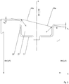
- FIG. 3 a vane ring according to an embodiment of the present invention is shown in a sectional view.
- the elements described are again provided with the same reference numerals, and for their description reference is made to the above explanations.
- the illustrated blade plate 21 is in the FIG. 3 represented in the nominal open position of the associated vane. To illustrate this opening position are in the figure (not to scale) the central axis X of the vane ring, the points p and q and their respective distances dist (p, X) and dist (q, X) to the central axis X drawn; the points p, q lie diametrically opposite each other on the edge of the surface of the blade plate 21 and with respect to the longitudinal axis A of the blade around which the blade is pivotable, in a common meridian plane of the central axis X.
- the offset between the point p (in the front surface portion 22a of the blade plate 21) and the inner ring surface (relative to the inner ring) in the radial direction r a step height h 1 , wherein the magnitude, that is not signed value is considered ,
- the heights h 1 and h 2 are each preferably in a range of 3% to 15% of the diameter of the blade plate, more preferably in a range of 5% to 10% of the diameter of the blade plate.
- the heights h 1 and h 2 are between 1 mm and 4 mm, more preferably between 1.5 and 2.5 mm.
- the height h 1 is greater than the height h 2 , so that the inventive reduction of the leakage flowing through the recess leakage effect mainly by the reduced mixing in the front surface portion 22 a of the blade plate and the resulting reduced suction effect of air into the gap 30 and while a deflection of the main flow through the surface of the blade plate (in particular in the rear surface portion 22b) is kept low.
- the blade plate has a substantially planar surface.
- the surface of the paddle (at least in one or more sections) may be convex (toward the airfoil) or concave (away from the airfoil), or have a corrugated surface (eg, sinusoidal in cross-section), and / or the front and rear surface areas may be at different levels. In this way, the blade plate surface may be adapted to the inner ring surface 22.
- An inventive vane ring for a turbomachine minimizes a leakage flow that passes through a recess 11, in which the paddle a Guide vane is used.
- the vane ring has a guide vane row with a plurality of guide vanes 20, each with an airfoil 24 and a blade plate 21 and an inner ring 10 with one of the plurality of vanes facing inner ring surface 12.
- the blade plates 21 have, viewed in the direction R of a provided main flow flowing through the turbomachine, a front and a rear surface region 22a, 22b.
- the front and / or the rear surface region 22a, 22b of at least one of the blade plates has a radial offset 31a, 31b relative to the inner ring surface 12 in a nominal and / or a maximum opening position of the stator blade (relative to a central axis X of the inner ring).
Landscapes
- Engineering & Computer Science (AREA)
- Mechanical Engineering (AREA)
- General Engineering & Computer Science (AREA)
- Physics & Mathematics (AREA)
- Fluid Mechanics (AREA)
- Structures Of Non-Positive Displacement Pumps (AREA)
Abstract
Description
- Die Erfindung betrifft einen Leitschaufelkranz mit einem Innenring und einer Mehrzahl an Leitschaufeln, eine Baugruppe für einen Leitschaufelkranz und eine Strömungsmaschine mit einem Leitschaufelkranz.
- Strömungsmaschinen wie Flugtriebwerke und stationäre Gasturbinen haben regelmäßig mindestens eine verdichterseitige und/oder eine turbinenseitige Leitschaufelreihe mit einer Vielzahl von Leitschaufeln. Die Leitschaufelreihe bildet mit einem Innenring einen sogenannten Leitschaufelkranz. Zur Einstellung optimaler Betriebsbedingungen sind dabei die Leitschaufeln vorzugsweise um ihre Längsachse verschwenkbar und können so verschiedene Schwenkstellungen einnehmen. Man spricht in diesem Fall auch von Verstellleitschaufeln.
- Der Innenring weist vorzugsweise in radialer Richtung eine Mehrzahl an Vertiefungen auf, in die jeweils ein Schaufelteller einer Leitschaufel eingesetzt ist. Eine radial äußere Lagerung der Leitschaufeln sowie deren Betätigung kann über Verstellzapfen der Leitschaufeln erfolgen, die mit einer entsprechenden Verstelleinrichtung am äußeren Gehäuse zusammenwirken können. An dem Innenring ist vorzugsweise ein Dichtungsträger geführt, der mit Dichtelementen bzw. Einlaufbelegen versehen ist, denen rotorseitige Dichtrippen gegenüberliegen.
- Im Betrieb tritt in den Spalt zwischen den Wandungen der Vertiefungen im Innenring und dem jeweils eingesetzten Schaufelteller an der Druckseite des Schaufelblatts an der (in Hauptstromrichtung) hinteren Seite des Innenrings Luft ein, die an der Saugseite des Schaufelblatts an der (in Hauptstromrichtung) vorderen Seite des Innenrings wieder austritt. Die durch diese Leckage entstehenden Verwirbelungen beeinflussen den Lufthauptstrom nachteilig und beeinträchtigen so den Wirkungsgrad der Strömungsmaschine.
- Die vorliegende Erfindung hat die Aufgabe, einen Leitschaufelkranz bzw. eine Strömungsmaschine bereitzustellen, bei dem /der die Leckage zwischen dem Innenring und einer eingesetzten Leitschaufel vermindert ist.
- Die Aufgabe wird gelöst durch einen Leitschaufelkranz gemäß Anspruch 1, eine Baugruppe für einen Leitschaufelkranz gemäß Anspruch 8 und eine Strömungsmaschine gemäß Anspruch 9. Vorteilhafte Ausführungsformen sind in den Unteransprüchen, der Beschreibung und den Figuren offenbart.
- Ein erfindungsgemäßer Leitschaufelkranz für eine Strömungsmaschine weist eine Leitschaufelreihe mit einer Mehrzahl von verschwenkbaren Leitschaufeln sowie einen Innenring mit einer der Mehrzahl von Leitschaufeln zugewandten Innenringoberfläche auf. Die Leitschaufeln haben jeweils ein Schaufelblatt und einen Schaufelteller. In einer nominalen und/oder in einer maximalen Öffnungsstellung der Leitschaufel weisen die Schaufelteller (an ihrer dem Schaufelblatt zugewandten Seite) in Richtung eines vorgesehenen, die Strömungsmaschine durchströmenden Hauptstroms betrachtet einen vorderen und einen hinteren Oberflächenbereich auf; der vordere und/oder der hintere Oberflächenbereich mindestens eines der Schaufelteller weist dabei einen (bezogen auf eine zentrale Achse des Innenrings) radialen Versatz zur Innenringoberfläche auf.
- Als "nominale Öffnungsstellung" ist dabei eine Drehstellung der Leitschaufel zu verstehen, in der für zwei Punkte, die auf dem Rand der Oberfläche des Leitschaufeltellers einander bezüglich der Längsachse des Schaufelblattes, um welche die Leitschaufel verschwenkbar ist, diametral gegenüber und dabei mit der zentralen Achse des Innenrings in einer gemeinsamen Ebene liegen, ein maximal möglicher Unterschied in den Abständen der Punkte zu der zentralen Achse des Innenrings, welche im bestimmungsgemäß verbauten Zustand mit der Rotationsachse bzw. Maschinenachse der Strömungsmaschine übereinstimmt, erreicht wird.
- Unter allen möglichen Drehstellungen der Leitschaufel und denjenigen einander (bezüglich des Schaufeltellers) diametral gegenüberliegenden Randunkten p, q des Schaufeltellers, die (in der jeweiligen Drehstellung) mit der zentralen Achse X des Innenrings des Leitschaufelkranzes in einer gemeinsamen (Meridian-)Ebene liegen, ergibt sich somit für die nominale Öffnungsstellung ein maximaler Unterschied

- In einer Strömungsmaschine ist vorzugsweise die Einstellung einer derartigen nominalen Öffnungsstellung für die Situation vorgesehen, dass die Strömungsmaschine eine Drehzahl hat, für die sie ausgelegt ist. Beispielsweise kann ein Flugzeugtriebwerk (als Strömungsmaschine) für einen sogenannten "Cruise-Mode" ausgelegt sein, nämlich für eine bestimmte Reisegeschwindigkeit in einer bestimmten Reisehöhe.
- Eine maximale Öffnungsstellung kann beispielsweise eingestellt sein, wenn der Hauptstrom (verglichen mit einer demgegenüber verschwenkten Leitschaufel) durch das Schaufelblatt eine minimale Richtungsänderung erfährt. Die Einstellung einer derartigen maximalen Öffnungsstellung kann beispielsweise bei einem Start eines Flugzeugtriebwerks (als Strömungsmaschine) vorgesehen sein.
- Die den Leitschaufeln zugewandte Innenringoberfläche und die (ihrem zugehörigen Schaufelblatt und damit ebenfalls den Leitschaufeln zugewandte) Oberfläche des Schaufeltellers verlaufen somit nicht entlang einer gemeinsamen, glatten Fläche, sondern der vordere und/oder der hintere Oberflächenbereich der Schaufeltelleroberfläche ist gegenüber der Innenringoberfläche versetzt, so dass also an einer Versatzstelle eine sich in (bezogen auf die zentrale Achse des Innenrings) radialer Richtung erhebende bzw. absenkende Stufe zwischen den besagten Oberflächen ausgebildet wird.
- So kann ein Luftstrom im Spalt zwischen Schaufelteller und Innenring in der Vertiefung reduziert und somit die Leckage vermindert werden. Dadurch kann die Pumpgrenze der Strömungsmaschine erhöht und ihr Wirkungsgrad verbessert werden.
- Eine erfindungsgemäße Baugruppe für einen Leitschaufelkranz umfasst einen Innenring und mindestens eine in eine Vertiefung des Innenrings einsetzbare Leitschaufel. Deren Teller umfasst einen - in Richtung eines vorgesehenen, die Strömungsmaschine durchströmenden Hauptstroms betrachtet - vorderen und einen hinteren Oberflächenbereich. Funktionsgemäß zusammengesetzt ergibt eine erfindungsgemäße Baugruppe einen erfindungsgemäßen Leitschaufelkranz gemäß einer der in dieser Schrift offenbarten Ausführungsformen.
- Eine erfindungsgemäße Strömungsmaschine weist einen erfindungsgemäßen Leitschaufelkranz gemäß einer der in dieser Schrift offenbarten Ausführungsformen auf.
- Gemäß einer vorteilhaften Ausführungsform der vorliegenden Erfindung ist der Oberflächenbereich des Schaufeltellers (in der nominalen und/oder der maximalen Öffnungsstellung der Leitschaufel) gegenüber der Innenringoberfläche abgesenkt. Insbesondere ist der vordere (dem Schaufelblatt zugewandte) Oberflächenbereich des Schaufeltellers bei dieser Ausführungsform vorzugsweise in einer den Schaufelteller umgebenden Vertiefung des Innenrings versenkt.
- Ein in die Strömungsmaschine eintretender Luftstrom wird dadurch vorteilhaft über den vorderen Oberflächenbereich hinweg geführt, so dass aus dem Spalt austretende Luft in diesem Bereich vor der Ausmischung mit dem Hauptstrom verzögert wird. Dadurch wird im hinteren Oberflächenbereich des Schaufeltellers zugleich eine Sogwirkung von Luft in den Spalt zwischen Schaufelteller und Innenring (in deren Vertiefung) reduziert. Insgesamt wird so der Leckageluftstrom vermindert.
- Alternativ oder zusätzlich kann gemäß einer vorteilhaften Ausführungsform der hintere Oberflächenbereich des Schaufeltellers (in der nominalen und/oder maximalen) Öffnungsstellung der Leitschaufel) gegenüber der Innenringoberfläche erhoben sein. Insbesondere ragt der hintere Oberflächenbereich des Schaufeltellers bei dieser Ausführungsform vorzugsweise aus einer den Schaufelteller umgebenden Vertiefung des Innenrings heraus, beispielsweise in den Hauptstrom hinein.
- Ein in die Strömungsmaschine eingetretener Hauptstrom wird somit vorteilhaft über den Spalt zwischen dem hinteren Oberflächenbereich des Schaufeltellers und dem Innenring hinweggeleitet. Ein Einströmen von Luft in den Spalt wird dadurch vermindert.
- Vorteilhaft sind Ausführungsformen, bei denen der Versatz - insbesondere bei nominaler und/oder maximaler Öffnungsstellung der Leitschaufel - des vorderen und/oder hinteren Oberflächenbereichs gegenüber der Innenringoberfläche eine (Stufen-)Höhe (als betragsmäßiger, somit nicht vorzeichenbehafteter Wert) zwischen 1mm und 4mm und/oder 3% bis 15 %, bevorzugt 5 % bis 10 % des Durchmessers des Schaufeltellers oder einer Kanalhöhe (bzw. eines Radius des Leitschaufelkranzes) beträgt. Dabei kann die Höhe des Versatzes parallel zur Leitschaufelachse (bzw. radial bezüglich des Innenrings) und vorzugsweise an einer Stelle gemessen werden, an der die Höhe maximal ist. Diese Abmessungen sind besonders günstig, um einerseits den Hauptstrom in die Strömungsmaschine zu führen und andererseits die geschilderte Leckageminderung zu erreichen. Seitlich der Maximalstellen flacht der Versatz vorzugsweise kontinuierlich ab.
- Sofern beide genannte Oberflächenbereiche des Schaufelblatts einen Versatz zur Innenringoberfläche ausbilden, können die jeweiligen (Stufen-)Höhen (als betragsmäßige, somit nicht vorzeichenbehaftete Werte) gleich oder verschieden groß sein. Somit können die Versätze an die durch die Innenringoberfläche bewirkte Strömungsführung angepasst sein.
- Auf diese Weise wird eine Beeinflussung des Hauptstroms im Bereich des Schaufeltellers relativ gering gehalten und die Minderung des Leckagestroms somit vorwiegend durch eine Ausbremsung von Luft bewirkt, die aus dem Spalt im vorderen Oberflächenbereich heraustritt; diese Ausbremsung hat wiederum vorteilhaft eine verringerte Sogwirkung in den Spalt im hinteren Oberflächenbereich zur Folge.
- Analog kann es vorteilhaft sein, wenn am vorderen Oberflächenbereich des Schaufeltellers ein Versatz wie genannt ausgebildet ist, der Schaufelteller im hinteren Oberflächenbereich jedoch im Wesentlichen stufenfrei zur Innenringoberfläche führt.
- Der Schaufelteller kann an der dem Schaufelblatt zugewandten Seite eine im Wesentlichen ebene Oberfläche, eine im Wesentlichen konvexe, eine im Wesentlichen konkave oder eine gewellte Oberfläche (vorzugsweise mit mindestens einem konkaven und konvexen Abschnitt) aufweisen. So kann der Schaufelteller an die Innenringoberfläche angepasst sein und dabei den Hauptstrom geeignet über den Versatz zwischen vorderem bzw. hinterem Oberflächenbereich und Innenringoberfläche leiten.
- Im Folgenden wird ein bevorzugtes Ausführungsbeispiel der Erfindung und zum Vergleich ein Ausschnitt eines Leitschaufelkranzes gemäß dem Stand der Technik anhand von Zeichnungen näher erläutert. Es versteht sich, dass einzelne Elemente und Komponenten auch anders kombiniert werden können als dargestellt.
- Es zeigen schematisch:
- Figur 1:
- einen Abschnitt eines Leitschaufelkranzes gemäß dem Stand der Technik;
- Figur 2:
- einen Abschnitt eines Leitschaufelkranzes gemäß einer Ausführungsform der vorliegenden Erfindung; und
- Figur 3:
- eine Schnittdarstellung eines Leitschaufelkranzes gemäß einer Ausführungsform der vorliegenden Erfindung.
- In der
Figur 1 ist ein Abschnitt eines herkömmlichen Leitschaufelkranzes dargestellt. Der Abschnitt umfasst einen Teil eines Innenrings 10 mit einer Vertiefung 11, in die ein Schaufelteller 21 einer Leitschaufel 20 eingesetzt ist. Die Leitschaufel 20 umfasst außer dem Schaufelteller 21 ein Schaufelblatt 24. Um dessen Längsachse A, die bezogen auf den Innenring (bzw. dessen (nicht gezeigte) zentrale Achse) in radialer Richtung r verläuft, ist die Leitschaufel verschwenkbar. In der Darstellung derFigur 1 befindet sich die Leitschaufel 20 in einer nominalen Öffnungsstellung. Ein vorgesehener Hauptstrom verläuft in einer Richtung R. - Der Leitschaufel 20 bzw. deren Schaufelblatt 24 zugewandt (und damit einer nicht gezeigten zentralen Achse des Innenringes abgewandt) sind eine Innenringoberfläche 12 und eine Oberfläche 22 des Schaufeltellers. Beide zusammen liegen entlang einer glatten Fläche und sind nur durch einen Spalt 30 im Wesentlichen stufenfrei voneinander getrennt.
- In der
Figur 2 ist ein Abschnitt eines erfindungsgemäßen Leitschaufelkranzes in einer analogen Darstellung gezeigt; Elemente, die denen des in derFigur 1 dargestellten Leitschaufelkranzes entsprechen, sind jeweils mit denselben Bezugszeichen versehen; für ihre Beschreibung wird auf die derFigur 1 verwiesen. - Die Oberfläche 21 der Leitschaufel 20 weist in der in
Figur 2 gezeigten Ausführungsform einen (in Bezug auf die vorgesehene Hauptstromrichtung R gesehen) vorderen Oberflächenbereich 22a und einen hinteren Oberflächenbereich 22b auf. Im dargestellten Ausführungsbeispiel bilden beide Oberflächenbereiche 22a, 22b (in der gezeigten nominalen Öffnungsstellung der Leitschaufel) am Spalt 30 einen (bezogen auf die zentrale Achse des Innenrings) radialen Versatz 31a bzw. 31b zur Innenringoberfläche 12 aus: Der vordere Oberflächenbereich 22a ist dabei gegenüber der Innenringoberfläche 12 (bzw. in die Vertiefung für den Schaufelteller hinein) abgesenkt, und der hintere Oberflächenbereich 22b ist gegenüber der Innenringoberfläche 12 erhoben (ragt also aus der Vertiefung für den Schaufelteller heraus). - Der Versatz 31a verzögt die Ausmischung einer Leckageströmung, die in diesem Bereich durch den Spalt 30 austritt, mit der Hauptströmung. Dadurch wird auch ein schädlicher Einfluss auf die Hauptströmung minimiert und zudem eine Sogwirkung von Luft in den Spalt, die insbesondere zwischen dem hinteren Oberflächenbereich 22b und der Innenringoberfläche 12 auftritt, reduziert.
- Der Versatz 31b reduziert zusätzlich das Eindringen von Luft in den Spalt 30 in diesem Bereich, weil der Hauptstrom durch diesen Versatz 31b über den Spalt hinweg geleitet wird.
- Insgesamt wird so die Leckageströmung minimiert.
- In
Figur 3 ist ein Leitschaufelkranz gemäß einer Ausführungsform der vorliegenden Erfindung in einer Schnittdarstellung gezeigt. Die bereits mit Bezug auf dieFiguren 1 und 2 beschriebenen Elemente sind wiederum mit denselben Bezugszeichen versehen, und für ihre Beschreibung wird auf die obigen Erläuterungen verwiesen. - Der gezeigte Schaufelteller 21 ist in der
Figur 3 in der nominalen Öffnungsstellung der zugehörigen Leitschaufel dargestellt. Zur Verdeutlichung dieser Öffnungsstellung sind in der Figur (nicht maßstabsgetreu) die zentrale Achse X des Leitschaufelkranzes, die Punkte p und q und deren jeweilige Abstände dist(p,X) bzw. dist(q,X) zur zentralen Achse X eingezeichnet; die Punkte p,q liegen jeweils auf dem Rand der Oberfläche des Schaufeltellers 21 und einander bezüglich der Längsachse A des Schaufelblattes, um welche die Leitschaufel verschwenkbar ist, diametral gegenüber, und zwar in einer gemeinsamen Meridianebene der zentralen Achse X. In der dargestellten nominalen Öffnungsstellung ist der (betragsmäßige) Unterschied U(p,q) = |dist(p, X) - dist(q, X)| unter allen möglichen Einstellungen der Leitschaufel maximal. Sind also nach einer Verdrehung der Leitschaufel zwei andere Punkte (hier nicht dargestellte) p', q' an den entsprechenden Positionen angeordnet (insbesondere ebenfalls einander diametral gegenüberliegend und in derselben Meridianebene wie dieFigur 3 zeigt), so weisen diese Punkte p', q' einen kleineren Unterschied im Abstand zur zentralen Achse X des Innenrings auf als p und q. - Wie in der
Figur 3 ferner zu erkennen ist, weist der Versatz zwischen dem Punkt p (im vorderen Oberflächenbereich 22a des Schaufeltellers 21) und der Innenringoberfläche (bezogen auf den Innenring) in radialer Richtung r eine Stufenhöhe h1 auf, wobei der betragsmäßige, also nicht vorzeichenbehaftete Wert betrachtet wird. - Dem Punkt p diametral gegenüber liegend ist im Punkt q ein Versatz zwischen dem hinteren Oberflächenbereich 22b des Schaufeltellers 21 und der Innenringoberfläche zu erkennen. In (bezogen auf den Innenring) radialer Richtung r weist dieser Versatz eine Stufenhöhe h2 auf.
- Die Höhen h1 und h2 liegen jeweils vorzugsweise in einem Bereich von 3 % bis 15 % des Durchmessers des Schaufeltellers, besonders bevorzugt in einem Bereich von 5 % bis 10 % des Durchmessers des Schaufeltellers. Vorteilhafterweise betragen die Höhen h1 und h2 zwischen 1mm und 4mm, bevorzugter zwischen 1,5 und 2,5 mm. Im dargestellten Beispiel ist die Höhe h1 größer als die Höhe h2, so dass die erfindungsgemäße Reduktion der durch die Vertiefung verlaufenden Leckageströmung vor allem durch die reduzierte Ausmischung im vorderen Oberflächenbereich 22a des Schaufeltellers und die resultierende verminderte Sogwirkung von Luft in den Spalt 30 bewirkt und dabei eine Umlenkung des Hauptstroms durch die Oberfläche des Schaufeltellers (insbesondere im hinteren Oberflächenbereich 22b) gering gehalten wird.
- In der gezeigten Ausführungsform weist der Schaufelteller eine im Wesentlichen ebene Oberfläche auf. In alternativen Ausführungsformen kann die Oberfläche des Schaufeltellers (zumindest in einem oder mehreren Abschnitt(en)) konvex (zum Schaufelblatt hin) oder konkav (vom Schaufelblatt weg) gewölbt sein oder eine gewellte Oberfläche (z.B. mit einem sinusförmigen Querschnitt) aufweisen, und/oder der vordere und der hintere Oberflächenbereich können auf verschiedenen Ebenen liegen. Auf diese Weise kann die Schaufeltelleroberfläche an die Innenringoberfläche 22 angepasst sein.
- Ein erfindungsgemäßer Leitschaufelkranz für eine Strömungsmaschine minimiert eine Leckageströmung, die durch eine Vertiefung 11 verläuft, in die der Schaufelteller einer Leitschaufel eingesetzt ist. Der Leitschaufelkranz weist eine Leitschaufelreihe mit einer Mehrzahl von Leitschaufeln 20 mit jeweils einem Schaufelblatt 24 und einem Schaufelteller 21 sowie einen Innenring 10 mit einer der Mehrzahl von Leitschaufeln zugewandten Innenringoberfläche 12 auf. Die Schaufelteller 21 haben - in Richtung R eines vorgesehenen, die Strömungsmaschine durchströmenden Hauptstroms betrachtet - einen vorderen und einen hinteren Oberflächenbereich 22a, 22b. Der vordere und/oder der hintere Oberflächenbereich 22a, 22b mindestens eines der Schaufelteller weist in einer nominalen und/oder einer maximalen Öffnungsstellung der Leitschaufel einen (bezogen auf eine zentrale Achse X des Innenrings) radialen Versatz 31a, 31b zur Innenringoberfläche 12 auf.
-
- 10
- Innenring
- 11
- Vertiefung
- 12
- Innenringoberfläche
- 20
- Leitschaufel
- 21
- Schaufelteller
- 22
- Schaufeltelleroberfläche
- 22a
- vorderer Oberflächenbereich
- 22b
- hinterer Oberflächenbereich
- 24
- Schaufelblatt
- 30
- Spalt
- 31a, 31b
- Versatz
- A
- Längsachse des Schaufelblatts
- h1, h2
- Höhe des Versatzes
- p, q
- einander diametral gegenüberliegende Punkte auf dem Rand des Schaufeltellers, die in einer gemeinsamen Meridianebene mit der Rotationsachse liegen
- r
- (bzgl. des Innenrings) radiale Richtung
- R
- Hauptstromrichtung
- X
- zentrale Achse des Innenrings (bzw. Maschinenachse der Strömungsmaschine)
Claims (9)
- Leitschaufelkranz für eine Strömungsmaschine, wobei der Leitschaufelkranz aufweist:eine Leitschaufelreihe mit einer Mehrzahl von verschwenkbaren Leitschaufeln (20) mit jeweils einem Schaufelblatt (24) und einem Schaufelteller (21); sowie einen Innenring (10) mit einer der Mehrzahl von Leitschaufeln zugewandten Innenringoberfläche (12),wobei die Schaufelteller (21) - in Richtung (R) eines vorgesehenen, die Strömungsmaschine durchströmenden Hauptstroms betrachtet - einen vorderen und einen hinteren Oberflächenbereich (22a, 22b) aufweisen,dadurch gekennzeichnet, dass bei mindestens einem der Schaufelteller in einer nominalen und/oder einer maximalen Öffnungsstellung der Leitschaufel der vordere und/oder der hintere Oberflächenbereich (22a, 22b) bezogen auf eine zentrale Achse (X) des Innenrings (10) einen radialen Versatz (31a, 31b) zur Innenringoberfläche (12) aufweist.
- Leitschaufelkranz gemäß Anspruch 1, wobei der vordere Oberflächenbereich (22a) des Schaufeltellers in der nominalen und/oder der maximalen Öffnungsstellung der Leitschaufel gegenüber der Innenringoberfläche (12) abgesenkt ist.
- Leitschaufelkranz gemäß Anspruch 2, wobei der Versatz (31a) zwischen dem vorderen Oberflächenbereich und der Innenringoberfläche eine Höhe (h1) aufweist, die 3 % bis 15 % des Durchmessers des Schaufeltellers (21) und/oder einer Kanalhöhe beträgt.
- Leitschaufelkranz gemäß einem der Ansprüche 1 bis 3, wobei der hintere Oberflächenbereich (22b) des Schaufeltellers in der maximalen Öffnungsstellung der Leitschaufel gegenüber der Innenringoberfläche (12) erhoben ist.
- Leitschaufelkranz gemäß Anspruch 4, wobei der Versatz (31b) zwischen dem hinteren Oberflächenbereich und der Innenringoberfläche eine Höhe (h2) aufweist, die 3 % bis 15 % des Durchmessers des Schaufeltellers (21) und/oder einer Kanalhöhe beträgt.
- Leitschaufelkranz gemäß einem der vorhergehenden Ansprüche, wobei der vordere und der hintere Oberflächenbereich (22a, 22b) in der nominalen und/oder maximalen Öffnungsstellung der Leitschaufel gegenüber der Innenringoberfläche einen Versatz im Wesentlichen gleicher Höhe (h1, h2) aufweisen.
- Leitschaufelkranz gemäß einem der vorhergehenden Ansprüche, wobei der mindestens eine Schaufelteller an der seinem Schaufelblatt zugewandten Seite eine im Wesentlichen ebene, eine im Wesentlichen konvexe, eine im Wesentlichen konkave oder eine gewellte Oberfläche (22) aufweist.
- Baugruppe für einen Leitschaufelkranz gemäß einem der vorhergehenden Ansprüche, wobei die Baugruppe einen Innenring (10) und mindestens eine in eine Vertiefung (11) des Innenrings einsetzbare Leitschaufel (20) aufweist.
- Strömungsmaschine mit einem Leitschaufelkranz gemäß einem der Ansprüche 1 bis 7.
Applications Claiming Priority (1)
| Application Number | Priority Date | Filing Date | Title |
|---|---|---|---|
| DE102016207212.9A DE102016207212A1 (de) | 2016-04-28 | 2016-04-28 | Leitschaufelkranz für eine Strömungsmaschine |
Publications (2)
| Publication Number | Publication Date |
|---|---|
| EP3246518A1 true EP3246518A1 (de) | 2017-11-22 |
| EP3246518B1 EP3246518B1 (de) | 2023-09-20 |
Family
ID=57960316
Family Applications (1)
| Application Number | Title | Priority Date | Filing Date |
|---|---|---|---|
| EP17154291.3A Active EP3246518B1 (de) | 2016-04-28 | 2017-02-02 | Leitschaufelkranz für eine strömungsmaschine und strömungsmaschine |
Country Status (3)
| Country | Link |
|---|---|
| US (1) | US10677076B2 (de) |
| EP (1) | EP3246518B1 (de) |
| DE (1) | DE102016207212A1 (de) |
Cited By (2)
| Publication number | Priority date | Publication date | Assignee | Title |
|---|---|---|---|---|
| WO2022022780A1 (de) * | 2020-07-30 | 2022-02-03 | MTU Aero Engines AG | Leitschaufelanordnung für eine strömungsmaschine, verdichtermodul und strömungsmaschine |
| EP4006315A1 (de) * | 2020-11-27 | 2022-06-01 | Pratt & Whitney Canada Corp. | Leitschaufel mit verstellbarer anstellung für ein gasturbinentriebwerk, verstellbare leitschaufelanordnung für ein gasturbinentriebwerk und zugehöriges betriebsverfahren |
Families Citing this family (3)
| Publication number | Priority date | Publication date | Assignee | Title |
|---|---|---|---|---|
| DE102016201766A1 (de) * | 2016-02-05 | 2017-08-10 | MTU Aero Engines AG | Leitschaufelsystem für eine Strömungsmaschine |
| FR3094746B1 (fr) * | 2019-04-03 | 2021-03-05 | Safran Aircraft Engines | Aube de stator a calage variable pour une turbomachine d’aeronef |
| DE102020210094A1 (de) | 2020-08-10 | 2022-02-10 | MTU Aero Engines AG | Verstellbare Leitschaufelanordnung |
Citations (3)
| Publication number | Priority date | Publication date | Assignee | Title |
|---|---|---|---|---|
| EP1188933A1 (de) * | 2000-09-18 | 2002-03-20 | Snecma Moteurs | Steuervorrichtung für verstellbare Leitschaufeln |
| WO2010079204A1 (fr) * | 2009-01-09 | 2010-07-15 | Snecma | Aube a calage variable pour etage de redresseur, comprenant une plateforme interne non circulaire |
| EP2884054A1 (de) * | 2013-12-10 | 2015-06-17 | MTU Aero Engines GmbH | Verstellbare Leitschaufel mit Kegelstumpf in einer Lageranordnung |
Family Cites Families (13)
| Publication number | Priority date | Publication date | Assignee | Title |
|---|---|---|---|---|
| FR2742799B1 (fr) * | 1995-12-20 | 1998-01-16 | Snecma | Palier d'extremite interne d'aube pivotante |
| GB0504588D0 (en) * | 2005-03-05 | 2005-04-13 | Rolls Royce Plc | Pivot ring |
| US8511978B2 (en) | 2006-05-02 | 2013-08-20 | United Technologies Corporation | Airfoil array with an endwall depression and components of the array |
| GB2459462B (en) * | 2008-04-23 | 2010-09-01 | Rolls Royce Plc | A variable stator vane |
| US8647067B2 (en) | 2008-12-09 | 2014-02-11 | General Electric Company | Banked platform turbine blade |
| US8459956B2 (en) | 2008-12-24 | 2013-06-11 | General Electric Company | Curved platform turbine blade |
| EP2405104A1 (de) * | 2010-07-08 | 2012-01-11 | Siemens Aktiengesellschaft | Verdichter und zugehöriges Gasturbinenkraftwerk |
| US20130011265A1 (en) | 2011-07-05 | 2013-01-10 | Alstom Technology Ltd. | Chevron platform turbine vane |
| US8864452B2 (en) | 2011-07-12 | 2014-10-21 | Siemens Energy, Inc. | Flow directing member for gas turbine engine |
| US9085985B2 (en) | 2012-03-23 | 2015-07-21 | General Electric Company | Scalloped surface turbine stage |
| WO2014130214A1 (en) | 2013-02-22 | 2014-08-28 | United Technologies Corporation | Stator vane assembly and method therefore |
| DE102013222980A1 (de) * | 2013-11-12 | 2015-06-11 | MTU Aero Engines AG | Leitschaufel für eine Strömungsmaschine mit einer Dichtungsvorrichtung, Leitrad sowie Strömungsmaschine |
| EP3090126B1 (de) | 2013-11-22 | 2022-05-11 | Raytheon Technologies Corporation | Bauteil eines gasturbinentriebwerks mit endwandkonturgraben |
-
2016
- 2016-04-28 DE DE102016207212.9A patent/DE102016207212A1/de not_active Withdrawn
-
2017
- 2017-02-02 EP EP17154291.3A patent/EP3246518B1/de active Active
- 2017-04-26 US US15/497,902 patent/US10677076B2/en active Active
Patent Citations (3)
| Publication number | Priority date | Publication date | Assignee | Title |
|---|---|---|---|---|
| EP1188933A1 (de) * | 2000-09-18 | 2002-03-20 | Snecma Moteurs | Steuervorrichtung für verstellbare Leitschaufeln |
| WO2010079204A1 (fr) * | 2009-01-09 | 2010-07-15 | Snecma | Aube a calage variable pour etage de redresseur, comprenant une plateforme interne non circulaire |
| EP2884054A1 (de) * | 2013-12-10 | 2015-06-17 | MTU Aero Engines GmbH | Verstellbare Leitschaufel mit Kegelstumpf in einer Lageranordnung |
Cited By (4)
| Publication number | Priority date | Publication date | Assignee | Title |
|---|---|---|---|---|
| WO2022022780A1 (de) * | 2020-07-30 | 2022-02-03 | MTU Aero Engines AG | Leitschaufelanordnung für eine strömungsmaschine, verdichtermodul und strömungsmaschine |
| US12326091B2 (en) | 2020-07-30 | 2025-06-10 | MTU Aero Engines AG | Guide vane arrangement for a turbomachine, compressor module, and turbomachine |
| EP4006315A1 (de) * | 2020-11-27 | 2022-06-01 | Pratt & Whitney Canada Corp. | Leitschaufel mit verstellbarer anstellung für ein gasturbinentriebwerk, verstellbare leitschaufelanordnung für ein gasturbinentriebwerk und zugehöriges betriebsverfahren |
| US11572798B2 (en) | 2020-11-27 | 2023-02-07 | Pratt & Whitney Canada Corp. | Variable guide vane for gas turbine engine |
Also Published As
| Publication number | Publication date |
|---|---|
| US10677076B2 (en) | 2020-06-09 |
| US20170314406A1 (en) | 2017-11-02 |
| DE102016207212A1 (de) | 2017-11-02 |
| EP3246518B1 (de) | 2023-09-20 |
Similar Documents
| Publication | Publication Date | Title |
|---|---|---|
| EP1260678B1 (de) | Segmentanordnung für Plattformen | |
| DE4242494C1 (en) | Adjustable flow-guide for engine exhaust turbocharger - has axially-adjustable annular insert in sectors forming different kinds of guide grilles supplied simultaneously by spiral passages | |
| EP0598174B1 (de) | Abgasturbolader für eine Brennkraftmaschine | |
| EP0799973B1 (de) | Wandkontur für eine axiale Strömungsmaschine | |
| EP3246518B1 (de) | Leitschaufelkranz für eine strömungsmaschine und strömungsmaschine | |
| EP0903468A1 (de) | Deckband für axialdurchströmte Turbine | |
| EP2881548B1 (de) | Gasturbinenverdichter | |
| DE112007002564T5 (de) | Diffusor und Auslasssystem für Turbine | |
| CH697806A2 (de) | Turbinenschaufel-Deckbandkantenprofil. | |
| EP1163425A1 (de) | Turbinenschaufel | |
| WO2019063384A1 (de) | Diffusor für einen verdichter | |
| DE102020201830B4 (de) | Leitschaufel-diffusor und zentrifugalkompressor | |
| WO2008122507A1 (de) | Shiplap-anordnung | |
| DE102006048933A1 (de) | Anordnung zur Strömungsbeeinflussung | |
| DE102015206384A1 (de) | Deckbandanordnung einer Schaufelreihe von Stator- oder Rotorschaufeln | |
| WO2005106207A1 (de) | Verdichterschaufel und verdichter | |
| EP2607625A1 (de) | Turbomaschine und Turbomaschinenstufe | |
| DE60305011T2 (de) | Verbesserte schaufelausführung zur verwendung in turboladern mit variabler geometrie | |
| DE102016124147B4 (de) | Innenkühlkonfigurationen in Turbinenrotorschaufeln | |
| EP3401504B1 (de) | Schaufelgitter | |
| EP3358135B1 (de) | Konturierung einer schaufelgitterplattform | |
| EP3682119A1 (de) | Diffusor für einen radialverdichter | |
| EP2607626A1 (de) | Turbomaschine und Turbomaschinenstufe | |
| DE112017005661T5 (de) | Variable Düseneinheit und Turbolader | |
| WO2008155243A1 (de) | Leitschaufelreihe |
Legal Events
| Date | Code | Title | Description |
|---|---|---|---|
| PUAI | Public reference made under article 153(3) epc to a published international application that has entered the european phase |
Free format text: ORIGINAL CODE: 0009012 |
|
| STAA | Information on the status of an ep patent application or granted ep patent |
Free format text: STATUS: THE APPLICATION HAS BEEN PUBLISHED |
|
| AK | Designated contracting states |
Kind code of ref document: A1 Designated state(s): AL AT BE BG CH CY CZ DE DK EE ES FI FR GB GR HR HU IE IS IT LI LT LU LV MC MK MT NL NO PL PT RO RS SE SI SK SM TR |
|
| AX | Request for extension of the european patent |
Extension state: BA ME |
|
| STAA | Information on the status of an ep patent application or granted ep patent |
Free format text: STATUS: REQUEST FOR EXAMINATION WAS MADE |
|
| 17P | Request for examination filed |
Effective date: 20180522 |
|
| RBV | Designated contracting states (corrected) |
Designated state(s): AL AT BE BG CH CY CZ DE DK EE ES FI FR GB GR HR HU IE IS IT LI LT LU LV MC MK MT NL NO PL PT RO RS SE SI SK SM TR |
|
| STAA | Information on the status of an ep patent application or granted ep patent |
Free format text: STATUS: EXAMINATION IS IN PROGRESS |
|
| 17Q | First examination report despatched |
Effective date: 20210721 |
|
| GRAP | Despatch of communication of intention to grant a patent |
Free format text: ORIGINAL CODE: EPIDOSNIGR1 |
|
| STAA | Information on the status of an ep patent application or granted ep patent |
Free format text: STATUS: GRANT OF PATENT IS INTENDED |
|
| INTG | Intention to grant announced |
Effective date: 20230424 |
|
| GRAS | Grant fee paid |
Free format text: ORIGINAL CODE: EPIDOSNIGR3 |
|
| GRAA | (expected) grant |
Free format text: ORIGINAL CODE: 0009210 |
|
| STAA | Information on the status of an ep patent application or granted ep patent |
Free format text: STATUS: THE PATENT HAS BEEN GRANTED |
|
| AK | Designated contracting states |
Kind code of ref document: B1 Designated state(s): AL AT BE BG CH CY CZ DE DK EE ES FI FR GB GR HR HU IE IS IT LI LT LU LV MC MK MT NL NO PL PT RO RS SE SI SK SM TR |
|
| REG | Reference to a national code |
Ref country code: GB Ref legal event code: FG4D Free format text: NOT ENGLISH |
|
| REG | Reference to a national code |
Ref country code: CH Ref legal event code: EP |
|
| REG | Reference to a national code |
Ref country code: IE Ref legal event code: FG4D Free format text: LANGUAGE OF EP DOCUMENT: GERMAN |
|
| REG | Reference to a national code |
Ref country code: DE Ref legal event code: R096 Ref document number: 502017015389 Country of ref document: DE |
|
| REG | Reference to a national code |
Ref country code: LT Ref legal event code: MG9D |
|
| PG25 | Lapsed in a contracting state [announced via postgrant information from national office to epo] |
Ref country code: GR Free format text: LAPSE BECAUSE OF FAILURE TO SUBMIT A TRANSLATION OF THE DESCRIPTION OR TO PAY THE FEE WITHIN THE PRESCRIBED TIME-LIMIT Effective date: 20231221 |
|
| REG | Reference to a national code |
Ref country code: NL Ref legal event code: MP Effective date: 20230920 |
|
| PG25 | Lapsed in a contracting state [announced via postgrant information from national office to epo] |
Ref country code: SE Free format text: LAPSE BECAUSE OF FAILURE TO SUBMIT A TRANSLATION OF THE DESCRIPTION OR TO PAY THE FEE WITHIN THE PRESCRIBED TIME-LIMIT Effective date: 20230920 Ref country code: RS Free format text: LAPSE BECAUSE OF FAILURE TO SUBMIT A TRANSLATION OF THE DESCRIPTION OR TO PAY THE FEE WITHIN THE PRESCRIBED TIME-LIMIT Effective date: 20230920 Ref country code: NO Free format text: LAPSE BECAUSE OF FAILURE TO SUBMIT A TRANSLATION OF THE DESCRIPTION OR TO PAY THE FEE WITHIN THE PRESCRIBED TIME-LIMIT Effective date: 20231220 Ref country code: LV Free format text: LAPSE BECAUSE OF FAILURE TO SUBMIT A TRANSLATION OF THE DESCRIPTION OR TO PAY THE FEE WITHIN THE PRESCRIBED TIME-LIMIT Effective date: 20230920 Ref country code: LT Free format text: LAPSE BECAUSE OF FAILURE TO SUBMIT A TRANSLATION OF THE DESCRIPTION OR TO PAY THE FEE WITHIN THE PRESCRIBED TIME-LIMIT Effective date: 20230920 Ref country code: HR Free format text: LAPSE BECAUSE OF FAILURE TO SUBMIT A TRANSLATION OF THE DESCRIPTION OR TO PAY THE FEE WITHIN THE PRESCRIBED TIME-LIMIT Effective date: 20230920 Ref country code: GR Free format text: LAPSE BECAUSE OF FAILURE TO SUBMIT A TRANSLATION OF THE DESCRIPTION OR TO PAY THE FEE WITHIN THE PRESCRIBED TIME-LIMIT Effective date: 20231221 Ref country code: FI Free format text: LAPSE BECAUSE OF FAILURE TO SUBMIT A TRANSLATION OF THE DESCRIPTION OR TO PAY THE FEE WITHIN THE PRESCRIBED TIME-LIMIT Effective date: 20230920 |
|
| PG25 | Lapsed in a contracting state [announced via postgrant information from national office to epo] |
Ref country code: NL Free format text: LAPSE BECAUSE OF FAILURE TO SUBMIT A TRANSLATION OF THE DESCRIPTION OR TO PAY THE FEE WITHIN THE PRESCRIBED TIME-LIMIT Effective date: 20230920 |
|
| PG25 | Lapsed in a contracting state [announced via postgrant information from national office to epo] |
Ref country code: IS Free format text: LAPSE BECAUSE OF FAILURE TO SUBMIT A TRANSLATION OF THE DESCRIPTION OR TO PAY THE FEE WITHIN THE PRESCRIBED TIME-LIMIT Effective date: 20240120 |
|
| PG25 | Lapsed in a contracting state [announced via postgrant information from national office to epo] |
Ref country code: ES Free format text: LAPSE BECAUSE OF FAILURE TO SUBMIT A TRANSLATION OF THE DESCRIPTION OR TO PAY THE FEE WITHIN THE PRESCRIBED TIME-LIMIT Effective date: 20230920 |
|
| PG25 | Lapsed in a contracting state [announced via postgrant information from national office to epo] |
Ref country code: SM Free format text: LAPSE BECAUSE OF FAILURE TO SUBMIT A TRANSLATION OF THE DESCRIPTION OR TO PAY THE FEE WITHIN THE PRESCRIBED TIME-LIMIT Effective date: 20230920 Ref country code: RO Free format text: LAPSE BECAUSE OF FAILURE TO SUBMIT A TRANSLATION OF THE DESCRIPTION OR TO PAY THE FEE WITHIN THE PRESCRIBED TIME-LIMIT Effective date: 20230920 Ref country code: IS Free format text: LAPSE BECAUSE OF FAILURE TO SUBMIT A TRANSLATION OF THE DESCRIPTION OR TO PAY THE FEE WITHIN THE PRESCRIBED TIME-LIMIT Effective date: 20240120 Ref country code: ES Free format text: LAPSE BECAUSE OF FAILURE TO SUBMIT A TRANSLATION OF THE DESCRIPTION OR TO PAY THE FEE WITHIN THE PRESCRIBED TIME-LIMIT Effective date: 20230920 Ref country code: EE Free format text: LAPSE BECAUSE OF FAILURE TO SUBMIT A TRANSLATION OF THE DESCRIPTION OR TO PAY THE FEE WITHIN THE PRESCRIBED TIME-LIMIT Effective date: 20230920 Ref country code: CZ Free format text: LAPSE BECAUSE OF FAILURE TO SUBMIT A TRANSLATION OF THE DESCRIPTION OR TO PAY THE FEE WITHIN THE PRESCRIBED TIME-LIMIT Effective date: 20230920 Ref country code: SK Free format text: LAPSE BECAUSE OF FAILURE TO SUBMIT A TRANSLATION OF THE DESCRIPTION OR TO PAY THE FEE WITHIN THE PRESCRIBED TIME-LIMIT Effective date: 20230920 Ref country code: PT Free format text: LAPSE BECAUSE OF FAILURE TO SUBMIT A TRANSLATION OF THE DESCRIPTION OR TO PAY THE FEE WITHIN THE PRESCRIBED TIME-LIMIT Effective date: 20240122 |
|
| PG25 | Lapsed in a contracting state [announced via postgrant information from national office to epo] |
Ref country code: PL Free format text: LAPSE BECAUSE OF FAILURE TO SUBMIT A TRANSLATION OF THE DESCRIPTION OR TO PAY THE FEE WITHIN THE PRESCRIBED TIME-LIMIT Effective date: 20230920 Ref country code: IT Free format text: LAPSE BECAUSE OF FAILURE TO SUBMIT A TRANSLATION OF THE DESCRIPTION OR TO PAY THE FEE WITHIN THE PRESCRIBED TIME-LIMIT Effective date: 20230920 |
|
| REG | Reference to a national code |
Ref country code: DE Ref legal event code: R097 Ref document number: 502017015389 Country of ref document: DE |
|
| PG25 | Lapsed in a contracting state [announced via postgrant information from national office to epo] |
Ref country code: DK Free format text: LAPSE BECAUSE OF FAILURE TO SUBMIT A TRANSLATION OF THE DESCRIPTION OR TO PAY THE FEE WITHIN THE PRESCRIBED TIME-LIMIT Effective date: 20230920 |
|
| PLBE | No opposition filed within time limit |
Free format text: ORIGINAL CODE: 0009261 |
|
| STAA | Information on the status of an ep patent application or granted ep patent |
Free format text: STATUS: NO OPPOSITION FILED WITHIN TIME LIMIT |
|
| PG25 | Lapsed in a contracting state [announced via postgrant information from national office to epo] |
Ref country code: DK Free format text: LAPSE BECAUSE OF FAILURE TO SUBMIT A TRANSLATION OF THE DESCRIPTION OR TO PAY THE FEE WITHIN THE PRESCRIBED TIME-LIMIT Effective date: 20230920 |
|
| 26N | No opposition filed |
Effective date: 20240621 |
|
| PG25 | Lapsed in a contracting state [announced via postgrant information from national office to epo] |
Ref country code: MC Free format text: LAPSE BECAUSE OF FAILURE TO SUBMIT A TRANSLATION OF THE DESCRIPTION OR TO PAY THE FEE WITHIN THE PRESCRIBED TIME-LIMIT Effective date: 20230920 |
|
| REG | Reference to a national code |
Ref country code: CH Ref legal event code: PL |
|
| PG25 | Lapsed in a contracting state [announced via postgrant information from national office to epo] |
Ref country code: LU Free format text: LAPSE BECAUSE OF NON-PAYMENT OF DUE FEES Effective date: 20240202 |
|
| PG25 | Lapsed in a contracting state [announced via postgrant information from national office to epo] |
Ref country code: CH Free format text: LAPSE BECAUSE OF NON-PAYMENT OF DUE FEES Effective date: 20240229 |
|
| PG25 | Lapsed in a contracting state [announced via postgrant information from national office to epo] |
Ref country code: SI Free format text: LAPSE BECAUSE OF FAILURE TO SUBMIT A TRANSLATION OF THE DESCRIPTION OR TO PAY THE FEE WITHIN THE PRESCRIBED TIME-LIMIT Effective date: 20230920 |
|
| PG25 | Lapsed in a contracting state [announced via postgrant information from national office to epo] |
Ref country code: SI Free format text: LAPSE BECAUSE OF FAILURE TO SUBMIT A TRANSLATION OF THE DESCRIPTION OR TO PAY THE FEE WITHIN THE PRESCRIBED TIME-LIMIT Effective date: 20230920 Ref country code: LU Free format text: LAPSE BECAUSE OF NON-PAYMENT OF DUE FEES Effective date: 20240202 Ref country code: CH Free format text: LAPSE BECAUSE OF NON-PAYMENT OF DUE FEES Effective date: 20240229 |
|
| PG25 | Lapsed in a contracting state [announced via postgrant information from national office to epo] |
Ref country code: BG Free format text: LAPSE BECAUSE OF FAILURE TO SUBMIT A TRANSLATION OF THE DESCRIPTION OR TO PAY THE FEE WITHIN THE PRESCRIBED TIME-LIMIT Effective date: 20230920 |
|
| PG25 | Lapsed in a contracting state [announced via postgrant information from national office to epo] |
Ref country code: BG Free format text: LAPSE BECAUSE OF FAILURE TO SUBMIT A TRANSLATION OF THE DESCRIPTION OR TO PAY THE FEE WITHIN THE PRESCRIBED TIME-LIMIT Effective date: 20230920 |
|
| REG | Reference to a national code |
Ref country code: BE Ref legal event code: MM Effective date: 20240229 |
|
| PG25 | Lapsed in a contracting state [announced via postgrant information from national office to epo] |
Ref country code: BE Free format text: LAPSE BECAUSE OF NON-PAYMENT OF DUE FEES Effective date: 20240229 |
|
| PG25 | Lapsed in a contracting state [announced via postgrant information from national office to epo] |
Ref country code: IE Free format text: LAPSE BECAUSE OF NON-PAYMENT OF DUE FEES Effective date: 20240202 |
|
| PG25 | Lapsed in a contracting state [announced via postgrant information from national office to epo] |
Ref country code: IE Free format text: LAPSE BECAUSE OF NON-PAYMENT OF DUE FEES Effective date: 20240202 Ref country code: BE Free format text: LAPSE BECAUSE OF NON-PAYMENT OF DUE FEES Effective date: 20240229 |
|
| REG | Reference to a national code |
Ref country code: AT Ref legal event code: MM01 Ref document number: 1613537 Country of ref document: AT Kind code of ref document: T Effective date: 20240202 |
|
| PG25 | Lapsed in a contracting state [announced via postgrant information from national office to epo] |
Ref country code: AT Free format text: LAPSE BECAUSE OF NON-PAYMENT OF DUE FEES Effective date: 20240202 |
|
| PG25 | Lapsed in a contracting state [announced via postgrant information from national office to epo] |
Ref country code: CY Free format text: LAPSE BECAUSE OF FAILURE TO SUBMIT A TRANSLATION OF THE DESCRIPTION OR TO PAY THE FEE WITHIN THE PRESCRIBED TIME-LIMIT; INVALID AB INITIO Effective date: 20170202 |
|
| PG25 | Lapsed in a contracting state [announced via postgrant information from national office to epo] |
Ref country code: HU Free format text: LAPSE BECAUSE OF FAILURE TO SUBMIT A TRANSLATION OF THE DESCRIPTION OR TO PAY THE FEE WITHIN THE PRESCRIBED TIME-LIMIT; INVALID AB INITIO Effective date: 20170202 |
|
| PG25 | Lapsed in a contracting state [announced via postgrant information from national office to epo] |
Ref country code: TR Free format text: LAPSE BECAUSE OF FAILURE TO SUBMIT A TRANSLATION OF THE DESCRIPTION OR TO PAY THE FEE WITHIN THE PRESCRIBED TIME-LIMIT Effective date: 20230920 |
|
| PGFP | Annual fee paid to national office [announced via postgrant information from national office to epo] |
Ref country code: GB Payment date: 20260219 Year of fee payment: 10 |
|
| PGFP | Annual fee paid to national office [announced via postgrant information from national office to epo] |
Ref country code: DE Payment date: 20260217 Year of fee payment: 10 |
|
| PGFP | Annual fee paid to national office [announced via postgrant information from national office to epo] |
Ref country code: FR Payment date: 20260219 Year of fee payment: 10 |