EP3246475B1 - Water outlet device for dispensing filtered water and tap water - Google Patents
Water outlet device for dispensing filtered water and tap water Download PDFInfo
- Publication number
- EP3246475B1 EP3246475B1 EP16002645.6A EP16002645A EP3246475B1 EP 3246475 B1 EP3246475 B1 EP 3246475B1 EP 16002645 A EP16002645 A EP 16002645A EP 3246475 B1 EP3246475 B1 EP 3246475B1
- Authority
- EP
- European Patent Office
- Prior art keywords
- outlet
- disposed
- tap water
- switch valve
- filtered water
- Prior art date
- Legal status (The legal status is an assumption and is not a legal conclusion. Google has not performed a legal analysis and makes no representation as to the accuracy of the status listed.)
- Active
Links
- XLYOFNOQVPJJNP-UHFFFAOYSA-N water Substances O XLYOFNOQVPJJNP-UHFFFAOYSA-N 0.000 title claims description 71
- 239000008399 tap water Substances 0.000 title claims description 66
- 235000020679 tap water Nutrition 0.000 title claims description 66
- 238000007789 sealing Methods 0.000 claims description 23
- 230000001419 dependent effect Effects 0.000 claims 2
- 238000010586 diagram Methods 0.000 description 8
- 239000012530 fluid Substances 0.000 description 8
- 238000001914 filtration Methods 0.000 description 3
- 238000004040 coloring Methods 0.000 description 2
- 238000005406 washing Methods 0.000 description 2
- 238000010411 cooking Methods 0.000 description 1
- 230000035622 drinking Effects 0.000 description 1
- 230000009977 dual effect Effects 0.000 description 1
- 238000005516 engineering process Methods 0.000 description 1
- 235000012055 fruits and vegetables Nutrition 0.000 description 1
- 238000005286 illumination Methods 0.000 description 1
- 230000004048 modification Effects 0.000 description 1
- 238000012986 modification Methods 0.000 description 1
- 239000002699 waste material Substances 0.000 description 1
Images


Classifications
-
- E—FIXED CONSTRUCTIONS
- E03—WATER SUPPLY; SEWERAGE
- E03C—DOMESTIC PLUMBING INSTALLATIONS FOR FRESH WATER OR WASTE WATER; SINKS
- E03C1/00—Domestic plumbing installations for fresh water or waste water; Sinks
- E03C1/02—Plumbing installations for fresh water
- E03C1/04—Water-basin installations specially adapted to wash-basins or baths
- E03C1/0404—Constructional or functional features of the spout
-
- F—MECHANICAL ENGINEERING; LIGHTING; HEATING; WEAPONS; BLASTING
- F16—ENGINEERING ELEMENTS AND UNITS; GENERAL MEASURES FOR PRODUCING AND MAINTAINING EFFECTIVE FUNCTIONING OF MACHINES OR INSTALLATIONS; THERMAL INSULATION IN GENERAL
- F16K—VALVES; TAPS; COCKS; ACTUATING-FLOATS; DEVICES FOR VENTING OR AERATING
- F16K11/00—Multiple-way valves, e.g. mixing valves; Pipe fittings incorporating such valves
- F16K11/10—Multiple-way valves, e.g. mixing valves; Pipe fittings incorporating such valves with two or more closure members not moving as a unit
- F16K11/20—Multiple-way valves, e.g. mixing valves; Pipe fittings incorporating such valves with two or more closure members not moving as a unit operated by separate actuating members
- F16K11/22—Multiple-way valves, e.g. mixing valves; Pipe fittings incorporating such valves with two or more closure members not moving as a unit operated by separate actuating members with an actuating member for each valve, e.g. interconnected to form multiple-way valves
-
- B—PERFORMING OPERATIONS; TRANSPORTING
- B01—PHYSICAL OR CHEMICAL PROCESSES OR APPARATUS IN GENERAL
- B01D—SEPARATION
- B01D35/00—Filtering devices having features not specifically covered by groups B01D24/00 - B01D33/00, or for applications not specifically covered by groups B01D24/00 - B01D33/00; Auxiliary devices for filtration; Filter housing constructions
- B01D35/02—Filters adapted for location in special places, e.g. pipe-lines, pumps, stop-cocks
- B01D35/04—Plug, tap, or cock filters filtering elements mounted in or on a faucet
-
- F—MECHANICAL ENGINEERING; LIGHTING; HEATING; WEAPONS; BLASTING
- F16—ENGINEERING ELEMENTS AND UNITS; GENERAL MEASURES FOR PRODUCING AND MAINTAINING EFFECTIVE FUNCTIONING OF MACHINES OR INSTALLATIONS; THERMAL INSULATION IN GENERAL
- F16K—VALVES; TAPS; COCKS; ACTUATING-FLOATS; DEVICES FOR VENTING OR AERATING
- F16K27/00—Construction of housing; Use of materials therefor
-
- B—PERFORMING OPERATIONS; TRANSPORTING
- B01—PHYSICAL OR CHEMICAL PROCESSES OR APPARATUS IN GENERAL
- B01D—SEPARATION
- B01D2201/00—Details relating to filtering apparatus
- B01D2201/16—Valves
-
- E—FIXED CONSTRUCTIONS
- E03—WATER SUPPLY; SEWERAGE
- E03C—DOMESTIC PLUMBING INSTALLATIONS FOR FRESH WATER OR WASTE WATER; SINKS
- E03C2201/00—Details, devices or methods not otherwise provided for
- E03C2201/40—Arrangement of water treatment devices in domestic plumbing installations
-
- E—FIXED CONSTRUCTIONS
- E03—WATER SUPPLY; SEWERAGE
- E03C—DOMESTIC PLUMBING INSTALLATIONS FOR FRESH WATER OR WASTE WATER; SINKS
- E03C2201/00—Details, devices or methods not otherwise provided for
- E03C2201/40—Arrangement of water treatment devices in domestic plumbing installations
- E03C2201/45—Arrangement of water treatment devices in domestic plumbing installations for carbonated water
Definitions
- the present invention relates to an outlet mechanism, particularly to an outlet mechanism with filtered water and tap water outlet modes.
- Taps are widely used in washrooms of families, hotels, restaurants, or in basins and water tanks of kitchens. People cares more and more about the health, water for cooking, washing fruits and vegetables and drinking needs to be filtered to use.
- taps with filtering function in the market There are taps with filtering function in the market. However, these taps only outlet filtered water. Water for washing products, hands or clothes needn't to be filtered. This kind of filtering tap with single function in long and high frequency usage would shorten the filtering element's service life, resulting in a waste of resource.
- DE 20 2006 004 399 U relates to a fluid armature for providing one or more fluids, wherein the fluid armature comprises a colour device for colouring of one or more fluids.
- the colouring of the fluid may be provided by illumination of the fluid and may indicate a temperature such as hot or cold of the fluid.
- Each fluid is guided through a conduit inside an armature tube and is illuminated shortly before leaving an outlet body of the tube.
- the document EP 0 896 176 A2 describes a faucet spout assembly for selectively dispensing treated or filtered water and untreated or unfiltered water.
- the faucet includes a valve assembly which is connectable to a handle 50 to facilitate control a volume and temperature of water to be dispensed by the faucet.
- the faucet spout assembly comprises a selector knob 62, which is formed with a cup-shaped body 308.
- the position of the selector knob 62 which is rotatable,determines the selection of unfiltered or filtered water.
- the document US 2005/0189023 A1 relates to a dual stand type faucet used in kitchen.
- a control valve 21 serves for controlling the mixing of cold and hot water.
- a handle 46 is installed in front of a water control stud 4, which can control a supply of clean water directly.
- the document US 6 220 298 B1 describes a faucet comprising a tubular body 11 and a head member 4.
- the head member 4 has a first section 41 and a second section 42, which is connected to the first section 42 with an included angle defined there between.
- Valve means are pivotably received in the second section 42 and has a rotor 54 pivotably received in the second section 42 of the head member 4.
- the present invention is provided with an outlet mechanism with filtered water and tap water outlet modes, which applies two independent outlet switches to respectively control two outlet modes to reduce the occurring of misoperation.
- An outlet mechanism with filtered water and tap water outlet modes comprising: an inlet body and an outlet body; the inlet body is connected to the outlet body, which is disposed independently with a tap water outlet passage and a filtered water outlet passage inside; a first outlet control switch an a second outlet controls switch be i ng respectively used to control the open and close of the tap water outlet passage and the filtered water outlet passage; the first outlet control switch is disposed on the inlet body, the second outlet control switch is disposed on the outlet body; and an outlet device being disposed at the end of the outlet body; the outlet device is disposed independently with a first outlet and a second outlet; the first outlet and the second outlet are respectively connected to the tap water outlet passage and the filtered water outlet passage, wherein the second outlet control switch comprises a switch valve button, the switch valve button is pressed to open or close the filtered water outlet passage.
- the outlet body comprises a support pipe and an outlet joint component; the support pipe is connected between the outlet joint component and the inlet body; the front end of the outlet joint component is disposed with a tap water flowing hole and a filtered water flowing hole, which form the tap water outlet passage and the filtered outlet passage; the end of the outlet joint component is disposed with a first opening; the side wall of the outlet joint component is further disposed with a second outlet vertical to the side wall.
- the switch valve component is disposed in the outlet joint component, the switch valve button is connected to one end of the switch valve component in transmitting way and is exposed out of the first open i ng.
- the switch valve component is further disposed with a sealing element; when the switch valve button is pressed, the sealing element moves in the switch valve component, such that the filtered water flowing hole is connected to the second opening or is closed by the sealing element.
- it comprises one or more tap water flowing hole.
- the switch valve component further comprises a push bar, one end of the push bar is connected to the switch valve button in transmitting way, the side wall of the other end is arranged with protruding blocks with interval, the end of the protruding block is configured to be an incline surface.
- the sealing element is coaxial to the push bar, the sealing element is disposed with a sealing ring vertical to the axial direction; the side of the sealing ring faced to the push bar is disposed with a plural ity of bosses; the side of the boss faced to the protruding block is disposed with a guiding surface coupled to the incline surface.
- the outlet device is disposed in the second opening; the first outlet and the second outlet are arranged in surrounding way, the first outlet surrounds the external periphery of the second outlet.
- the inlet body comprises a body base and an independent valve spool base disposed in the body base; the independent valve spool base is disposed independently with a filtered water inlet and a tap water inlet, the filtered water inlet is connected to the filtered water outlet passage; the side wall of the independent valve spool base is disposed with a tap water outlet; the first outlet control switch is disposed between the tap water outlet and the tap water flowing hole; when the first outlet control switch is switched on or off, the tap water outlet is connected or disconnected to the tap water flowing hole.
- it comprises two tap water inlets: a cool water inlet and a hot water inlet.
- an outlet mechanism with filtered water and tap water outlet modes comprises:
- An inlet body 2 an outlet body 1, an outlet device 3, a first outlet control switch 4 and a second outlet control switch 5; the inlet body 2 is connected to the outlet body 1, which is disposed independently with a tap water outlet passage 13 and a filtered water outlet passage 14 inside;
- the outlet body 1 comprises a support pipe 11 and an outlet joint component 12; the support pipe 11 is connected between the outlet joint component 12 and the inlet body 2; the front end of the outlet joint component 12 is disposed with a tap water flowing hole 122 and a filtered water flowing hole 121, which form the tap water outlet passage 13 and the filtered outlet passage 14; the end of the outlet joint component 12 is disposed with a first opening 123; the side wall of the outlet joint component 12 is further disposed with a second outlet 124 vertical to the side wall.
- the outlet device 3 is disposed in the second opening 124, the outlet device 3 is disposed independently with a first outlet 31 and a second outlet 32; the first outlet 31 and the second outlet 32 are respectively connected to the tap water outlet passage 13 and the filtered water outlet passage 14.
- the first outlet 31 and the second outlet 32 are arranged in surrounding way, the first outlet 31 surrounds the external periphery of the second outlet 32.
- the first outlet control switch 4 is disposed on the inlet body 2
- the second outlet control switch 5 is disposed on the outlet body 1; the switches are respectively used to control the open and close of the tap water outlet passage 13 and the filtered water outlet passage 14.
- the second outlet control switch 5 comprises a switch valve component 51 and a switch valve button 52; the switch valve component 51 is disposed in the outlet joint component 12, the switch valve button 52 is connected to one end of the switch valve component 51 in transmitting way and is exposed out of the first opening 123.
- the switch valve component 51 is further disposed with a push bar 53 and a sealing element 54, one end of the push bar 53 is connected to the switch valve button 52 in transmitting way, the side wall of the other end is arranged with protruding blocks 531 with interval, the end of the protruding block 531 is configured to be an incline surface.
- the sealing element 54 is coaxial to the push bar 53, the sealing element 54 is disposed with a sealing ring 541 vertical to the axial direction; the side of the sealing ring 541 faced to the push bar is disposed with a plurality of bosses 542; the side of the boss 542 faced to the protruding block 531 is disposed with a guiding surface 543 coupled to the incline surface.
- the inlet body 2 comprises a body base 21 and an independent valve spool base 22 disposed in the body base 21;
- the independent valve spool base 22 is disposed independently with a filtered water inlet 221 and a tap water inlet 222, the filtered water inlet 221 is connected to the filtered water outlet passage 14; the side wall of the independent valve spool base is disposed with a tap water outlet 223; the first outlet control switch 4 is disposed between the tap water outlet 223 and the tap water flowing hole 122; when the first outlet control switch 4 is switched on or off, the tap water outlet 223 is connected or disconnected to the tap water flowing hole122. Therefore, the tap water outlet passage 13 is controlled by the first outlet control switch 4.
- the tap water outlet passage 13 is adjustable, which satisfies the requirement and using habit.
- the tap water outlet passage 13 is one or more than one as well, two preferred, such to guarantee the outlet volume of the tap water.
- the outlet mechanism with filtered water and tap water outlet modes comprises independent first outlet contro I switch and second outlet control switch to respectively control the tap water outlet and filtered water outlet; in addition, the first outlet control switch is disposed on the inlet body, the second outlet control switch is disposed on the outlet body, such that the user can separate the two switches clearly, thus efficiently avoiding misoperation.
- outlet mechanism with filtered water and tap water outlet modes is provided that the filtered water ad the tap water share one outlet device, the outlet device is disposed with independent filtered water outlet and tap water outlet, such to guarantee an clean and attractive appearance of the outlet mechanism and to ensure the outlet waterways of the filtered water and the tap water not influencing each other, thus ensuring the outlet consistency of each outlet mode.
- the present invention is provided with an outlet mechanism with filtered water and tap water outlet modes, comprising: an inlet body and an outlet body; the inlet body is connected to the outlet body, which is disposed independently with a tap water outlet passage and a filtered water outlet passage inside; a first outlet control switch an a second outlet controls switch being respectively used to control the open and close of the tap water outlet passage and the filtered water outlet passage; the first outlet control switch is disposed on the inlet body, the second outlet control switch is disposed on the outlet body; and an outlet dev i ce be i ng d i sposed at the end of the outlet body; the outlet device is disposed independently with a first outlet and a second outlet; the first outlet and the second outlet are respectively connected to the tap water out let passage and the filtered water outlet passage.
- the present invention is provided with an outlet mechanism with filtered water and tap water outlet modes, which applies two independent outlet switches to respectively control two outlet modes to reduce the occurring of misoperation.
Description
- The present invention relates to an outlet mechanism, particularly to an outlet mechanism with filtered water and tap water outlet modes.
- Taps are widely used in washrooms of families, hotels, restaurants, or in basins and water tanks of kitchens. People cares more and more about the health, water for cooking, washing fruits and vegetables and drinking needs to be filtered to use. There are taps with filtering function in the market. However, these taps only outlet filtered water. Water for washing products, hands or clothes needn't to be filtered. This kind of filtering tap with single function in long and high frequency usage would shorten the filtering element's service life, resulting in a waste of resource.
-
DE 20 2006 004 399 U relates to a fluid armature for providing one or more fluids, wherein the fluid armature comprises a colour device for colouring of one or more fluids. The colouring of the fluid may be provided by illumination of the fluid and may indicate a temperature such as hot or cold of the fluid. Each fluid is guided through a conduit inside an armature tube and is illuminated shortly before leaving an outlet body of the tube. Thedocument EP 0 896 176 A2 describes a faucet spout assembly for selectively dispensing treated or filtered water and untreated or unfiltered water. The faucet includes a valve assembly which is connectable to a handle 50 to facilitate control a volume and temperature of water to be dispensed by the faucet. Further, the faucet spout assembly comprises a selector knob 62, which is formed with a cup-shaped body 308. The position of the selector knob 62, which is rotatable,determines the selection of unfiltered or filtered water. The documentUS 2005/0189023 A1 relates to a dual stand type faucet used in kitchen. Acontrol valve 21 serves for controlling the mixing of cold and hot water. A handle 46 is installed in front of awater control stud 4, which can control a supply of clean water directly. The documentUS 6 220 298 B1 describes a faucet comprising atubular body 11 and ahead member 4. Thehead member 4 has a first section 41 and a second section 42, which is connected to the first section 42 with an included angle defined there between. Valve means are pivotably received in the second section 42 and has arotor 54 pivotably received in the second section 42 of thehead member 4. - The present invention is provided with an outlet mechanism with filtered water and tap water outlet modes, which applies two independent outlet switches to respectively control two outlet modes to reduce the occurring of misoperation.
- The technical solution of the present invention is provided by the subject matter of
claim 1. - An outlet mechanism with filtered water and tap water outlet modes, wherein comprising: an inlet body and an outlet body; the inlet body is connected to the outlet body, which is disposed independently with a tap water outlet passage and a filtered water outlet passage inside;
a first outlet control switch an a second outlet controls switch be i ng respectively used to control the open and close of the tap water outlet passage and the filtered water outlet passage; the first outlet control switch is disposed on the inlet body, the second outlet control switch is disposed on the outlet body; and
an outlet device being disposed at the end of the outlet body; the outlet device is disposed independently with a first outlet and a second outlet; the first outlet and the second outlet are respectively connected to the tap water outlet passage and the filtered water outlet passage, wherein the second outlet control switch comprises a switch valve button, the switch valve button is pressed to open or close the filtered water outlet passage. - In another preferred embodiment, the outlet body comprises a support pipe and an outlet joint component; the support pipe is connected between the outlet joint component and the inlet body; the front end of the outlet joint component is disposed with a tap water flowing hole and a filtered water flowing hole, which form the tap water outlet passage and the filtered outlet passage; the end of the outlet joint component is disposed with a first opening; the side wall of the outlet joint component is further disposed with a second outlet vertical to the side wall.
- In another preferred embodiment, the switch valve component is disposed in the outlet joint component, the switch valve button is connected to one end of the switch valve component in transmitting way and is exposed out of the first open i ng. In another preferred embodiment, the switch valve component is further disposed with a sealing element; when the switch valve button is pressed, the sealing element moves in the switch valve component, such that the filtered water flowing hole is connected to the second opening or is closed by the sealing element.
- In another preferred embodiment, it comprises one or more tap water flowing hole.
- In another preferred embodiment, the switch valve component further comprises a push bar, one end of the push bar is connected to the switch valve button in transmitting way, the side wall of the other end is arranged with protruding blocks with interval, the end of the protruding block is configured to be an incline surface.
- In another preferred embodiment, the sealing element is coaxial to the push bar, the sealing element is disposed with a sealing ring vertical to the axial direction; the side of the sealing ring faced to the push bar is disposed with a plural ity of bosses; the side of the boss faced to the protruding block is disposed with a guiding surface coupled to the incline surface.
- In another preferred embodiment, the outlet device is disposed in the second opening; the first outlet and the second outlet are arranged in surrounding way, the first outlet surrounds the external periphery of the second outlet.
- In another preferred embodiment, the inlet body comprises a body base and an independent valve spool base disposed in the body base; the independent valve spool base is disposed independently with a filtered water inlet and a tap water inlet, the filtered water inlet is connected to the filtered water outlet passage; the side wall of the independent valve spool base is disposed with a tap water outlet; the first outlet control switch is disposed between the tap water outlet and the tap water flowing hole; when the first outlet control switch is switched on or off, the tap water outlet is connected or disconnected to the tap water flowing hole.
- In another preferred embodiment, it comprises two tap water inlets: a cool water inlet and a hot water inlet.
- Compared to the traditional technology, the technical solution of the present invention has following advantages:
- 1. The outlet mechanism with filtered water and tap water outlet modes is provided that it comprises independent first outlet control switch and second outlet control switch to respectively control the tap water outlet and filtered water outlet; in addition, the first outlet control switch is disposed on the inlet body, the second outlet control switch is disposed on the outlet body, such that the user can separate the two switches clearly, thus efficiently avoiding misoperation.
- 2. Above mentioned outlet mechanism with filtered water and tap water outlet modes is provided that the filtered water ad the tap water share one outlet device, the outlet device is disposed with independent filtered water outlet and tap water outlet, such to guarantee an clean and attractive appearance of the outlet mechanism and to ensure the outlet waterways of the filtered water and the tap water not influencing each other, thus ensuring the outlet consistency of each outlet mode.
-
-
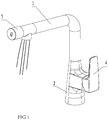
FIG.1 illustrates a schematic diagram of an outlet mechanism of a preferred embodiment of the present invention. -
FIG.2 illustrates an exploded and schematic diagram of the outlet mechanism of the preferred embodiment of the present invention. -
FIG. 3 illustrates a sectional diagram of the outlet mechanism with waterways of the preferred embodiment of the present invention. -
FIG. 4 illustrates a schematic diagram of an outlet joint component of the preferred embodiment of the present invention. -
FIG.5 illustrates a schematic diagram of a switch valve component of the preferred embodiment of the present invention. -
FIG. 6 illustrates a schematic diagram of a push bar and a sealing element of the switch valve component of the preferred embodiment of the present invention. -
FIG. 7 illustrates a schematic diagram of an independent valve spool base of the preferred embodiment of the present invention. -
FIG. 8 illustrates a sectional diagram of the independent valve spool base and a first outlet control switch of the preferred embodiment of the present invention. - The present invention will be further descried with the drawings and the embodiment.
- Referring to
FIGS 1-8 , an outlet mechanism with filtered water and tap water outlet modes comprises: - An
inlet body 2, anoutlet body 1, anoutlet device 3, a firstoutlet control switch 4 and a secondoutlet control switch 5; theinlet body 2 is connected to theoutlet body 1, which is disposed independently with a tapwater outlet passage 13 and a filteredwater outlet passage 14 inside; - The
outlet body 1 comprises asupport pipe 11 and anoutlet joint component 12; thesupport pipe 11 is connected between theoutlet joint component 12 and theinlet body 2; the front end of theoutlet joint component 12 is disposed with a tapwater flowing hole 122 and a filteredwater flowing hole 121, which form the tapwater outlet passage 13 and the filteredoutlet passage 14; the end of theoutlet joint component 12 is disposed with afirst opening 123; the side wall of theoutlet joint component 12 is further disposed with asecond outlet 124 vertical to the side wall. - The
outlet device 3 is disposed in thesecond opening 124, theoutlet device 3 is disposed independently with afirst outlet 31 and asecond outlet 32; thefirst outlet 31 and thesecond outlet 32 are respectively connected to the tapwater outlet passage 13 and the filteredwater outlet passage 14. In this embodiment, thefirst outlet 31 and thesecond outlet 32 are arranged in surrounding way, thefirst outlet 31 surrounds the external periphery of thesecond outlet 32. - The first
outlet control switch 4 is disposed on theinlet body 2, the secondoutlet control switch 5 is disposed on theoutlet body 1; the switches are respectively used to control the open and close of the tapwater outlet passage 13 and the filteredwater outlet passage 14. - The second
outlet control switch 5 comprises aswitch valve component 51 and aswitch valve button 52; theswitch valve component 51 is disposed in theoutlet joint component 12, theswitch valve button 52 is connected to one end of theswitch valve component 51 in transmitting way and is exposed out of thefirst opening 123. - The
switch valve component 51 is further disposed with apush bar 53 and asealing element 54, one end of thepush bar 53 is connected to theswitch valve button 52 in transmitting way, the side wall of the other end is arranged with protrudingblocks 531 with interval, the end of the protrudingblock 531 is configured to be an incline surface. - The sealing
element 54 is coaxial to thepush bar 53, the sealingelement 54 is disposed with a sealingring 541 vertical to the axial direction; the side of the sealingring 541 faced to the push bar is disposed with a plurality ofbosses 542; the side of theboss 542 faced to the protrudingblock 531 is disposed with a guidingsurface 543 coupled to the incline surface. - When the
switch valve button 52 is pressed, the guidingsurface 543 is coupled to the incline surface of the end of theprotruding block 531, thesealing element 54 is pushed to move in theswitch valve component 51, such that the filteredwater flowing hole 121 is connected to thesecond opening 124, this outlet mode is filtered water. When theswitch valve button 52 is pressed again, the sealingelement 54 repositions, the filteredwater flowing hole 121 is disconnected to thesecond opening 124. - The
inlet body 2 comprises abody base 21 and an independentvalve spool base 22 disposed in thebody base 21; - The independent
valve spool base 22 is disposed independently with a filteredwater inlet 221 and atap water inlet 222, the filteredwater inlet 221 is connected to the filteredwater outlet passage 14; the side wall of the independent valve spool base is disposed with atap water outlet 223; the firstoutlet control switch 4 is disposed between thetap water outlet 223 and the tapwater flowing hole 122; when the firstoutlet control switch 4 is switched on or off, thetap water outlet 223 is connected or disconnected to the tap water flowing hole122. Therefore, the tapwater outlet passage 13 is controlled by the firstoutlet control switch 4. - In this embodiment, it comprises two tap water inlets 222: a cool water inlet and a hot water inlet. The outlet temperature of the tap
water outlet passage 13 is adjustable, which satisfies the requirement and using habit. - In this embodiment, it comprises one or more than one tap water flowing hole. The number of the tap
water outlet passage 13 is one or more than one as well, two preferred, such to guarantee the outlet volume of the tap water. - The outlet mechanism with filtered water and tap water outlet modes is provided that it comprises independent first outlet contro I switch and second outlet control switch to respectively control the tap water outlet and filtered water outlet; in addition, the first outlet control switch is disposed on the inlet body, the second outlet control switch is disposed on the outlet body, such that the user can separate the two switches clearly, thus efficiently avoiding misoperation.
- In addition, above mentioned outlet mechanism with filtered water and tap water outlet modes is provided that the filtered water ad the tap water share one outlet device, the outlet device is disposed with independent filtered water outlet and tap water outlet, such to guarantee an clean and attractive appearance of the outlet mechanism and to ensure the outlet waterways of the filtered water and the tap water not influencing each other, thus ensuring the outlet consistency of each outlet mode.
- The invention may be summarized as follows: The present invention is provided with an outlet mechanism with filtered water and tap water outlet modes, comprising: an inlet body and an outlet body; the inlet body is connected to the outlet body, which is disposed independently with a tap water outlet passage and a filtered water outlet passage inside; a first outlet control switch an a second outlet controls switch being respectively used to control the open and close of the tap water outlet passage and the filtered water outlet passage; the first outlet control switch is disposed on the inlet body, the second outlet control switch is disposed on the outlet body; and an outlet dev i ce be i ng d i sposed at the end of the outlet body; the outlet device is disposed independently with a first outlet and a second outlet; the first outlet and the second outlet are respectively connected to the tap water out let passage and the filtered water outlet passage. The present invention is provided with an outlet mechanism with filtered water and tap water outlet modes, which applies two independent outlet switches to respectively control two outlet modes to reduce the occurring of misoperation.
- Although the present invention has been described with reference to the preferred embodiments thereof for carrying out the patent for invention, it is apparent to those skilled in the art that a variety of modifications and changes may be made without departing from the scope of the patent for invention which is intended to be defined by the appended claims.
Claims (11)
- An outlet mechanism with filtered water and tap water outlet modes, said mechanism comprising:an inlet body (2) and an outlet body (1); the inlet body (2) being connected to the outlet body (1), the outlet body (1) being provided independently with a tap water outlet passage (13) and a filtered water outlet passage (14) inside;a first outlet control switch (4) and a second outlet control switch (5) being respectively used to control the open and close of the tap water outlet passage (13) and the filtered water outlet passage (14); the first outlet control switch (4) being disposed on the inlet body (2), the second outlet control switch (5) being disposed on the outlet body (1); andan outlet device (3) being disposed at the end of the outlet body (1); characterized in that the outlet device (3) is disposed independently with a first outlet (31) and a second outlet (32); the first outlet (31) and the second outlet (32) are respectively connected to the tap water outlet passage (13) and the filtered water outlet passage (14),wherein the second outlet control switch (5) comprises a switch valve button (52), the switch valve button (52) being pressed to open or close the filtered water outlet passage (14).
- The outlet mechanism according to claim 1, wherein the outlet body (1) comprises a support pipe (11) and an outlet joint component (12); the support pipe (11) is connected between the outlet joint component (12) and the inlet body (2); a front end of the outlet joint component (12) is disposed with a tap water flowing hole (122) and a filtered water flowing hole (121), which form the tap water outlet passage (13) and the filtered outlet passage (14); the other end of the outlet joint component (12) is disposed with a first opening (123); a side wall of the outlet joint component (12) is further disposed with a second opening (124) vertical to the side wall.
- The outlet mechanism according to claim 2, wherein the second outlet control switch (5) comprises a switch valve component (51) and the switch valve button (52); the switch valve component (51) is disposed in the outlet joint component (12), the switch valve button (52) is connected to one end of the switch valve component (51) in transmitting way and is exposed out of the first opening (123).
- The outlet mechanism according to claim 3, wherein the switch valve component (51) is further disposed with a sealing element (54); when the switch valve button (52) is pressed, the sealing element (54) moves in the switch valve component (51), such that the filtered water flowing hole (121) is connected to a second opening (124) or is closed by the sealing element (54).
- The outlet mechanism according to claim 2, wherein comprising a plurality of tap water flowing holes (122).
- The outlet mechanism according to any one or more of claims 3 to 5, wherein the switch valve component (51) further comprises a push bar (53), one end of the push bar (53) is connected to the switch valve button (52) in transmitting way, the side wall of the other end of the push bar (53) is arranged with protruding blocks (531) with interval, the end of the protruding blocks (531) being configured to be an incline surface.
- The outlet mechanism according to claim 6, wherein the sealing element (54) is coaxial to the push bar (53), the sealing element (54) is disposed with a sealing ring (541) vertical to the axial direction; the side of the sealing ring (541) faced to the push bar (53) is disposed with a plurality of bosses (542); the side of the bosses (542) faced to the protruding blocks (531) are disposed with a guiding surface (543) coupled to the incline surface.
- The outlet mechanism according to claim 2 or any claim dependent thereof, wherein the outlet device (3) is disposed in the second opening (124); the first outlet (31) and the second outlet (32) are arranged in surrounding way, the first outlet (31) surrounds the external periphery of the second outlet (32).
- The outlet mechanism according to claim 2 or any claim dependent thereof, wherein the inlet body (2) comprises a body base (21) and an independent valve spool base (22) disposed in the body base (21); the independent valve spool base (22) is disposed independently with a filtered water inlet (221) and a tap water inlet (222), the filtered water inlet (221) is connected to the filtered water outlet passage (14); the side wall of the independent valve spool base (22) is disposed with a tap water outlet (223); the first outlet control switch (4) is disposed between the tap water outlet (223) and the tap water flowing hole (122); when the first outlet control switch (4) is switched on or off, the tap water outlet (223) is connected or disconnected to the tap water flowing hole (122).
- The outlet mechanism according to claim 9, wherein comprising two tap water inlets (222): a cool water inlet and a hot water inlet.
- The outlet mechanism according to any one or more of claims 4 to 10, characterized in that when the switch valve button (52) is pressed the filtered water flowing hole (121) of the outlet joint component (12) is connected to the second opening (124) and when the switch valve button (52) is pressed again, the sealing element (54) repositions, and the filtered water flowing hole (121) is disconnected to the second opening (124).
Applications Claiming Priority (1)
| Application Number | Priority Date | Filing Date | Title |
|---|---|---|---|
| CN201610324319.9A CN107387816A (en) | 2016-05-16 | 2016-05-16 | A kind of discharge mechanism for possessing two kinds of water exit modes of filter water and light water |
Publications (2)
| Publication Number | Publication Date |
|---|---|
| EP3246475A1 EP3246475A1 (en) | 2017-11-22 |
| EP3246475B1 true EP3246475B1 (en) | 2021-08-04 |
Family
ID=57758377
Family Applications (1)
| Application Number | Title | Priority Date | Filing Date |
|---|---|---|---|
| EP16002645.6A Active EP3246475B1 (en) | 2016-05-16 | 2016-12-13 | Water outlet device for dispensing filtered water and tap water |
Country Status (3)
| Country | Link |
|---|---|
| US (1) | US10400428B2 (en) |
| EP (1) | EP3246475B1 (en) |
| CN (1) | CN107387816A (en) |
Families Citing this family (9)
| Publication number | Priority date | Publication date | Assignee | Title |
|---|---|---|---|---|
| USD829305S1 (en) * | 2016-07-01 | 2018-09-25 | Xiamen Solex High-Tech Industries Co., Ltd. | Water purifying tap |
| CN108223878A (en) * | 2018-01-25 | 2018-06-29 | 珠海普乐美厨卫有限公司 | A kind of button Multifunctional water purification tap |
| CN109058551A (en) * | 2018-11-02 | 2018-12-21 | 江门市依洛娜卫浴有限公司 | A kind of multi-function water tap |
| CN109723862A (en) * | 2019-01-11 | 2019-05-07 | 玉环达丰环保设备有限公司 | With it is double enter water function ultraviolet sterilization faucet |
| USD915563S1 (en) * | 2019-02-05 | 2021-04-06 | Grohe Ag | Faucet handspray |
| USD913434S1 (en) * | 2019-02-05 | 2021-03-16 | Grohe Ag | Faucet |
| USD913435S1 (en) * | 2019-02-05 | 2021-03-16 | Grohe Ag | Faucet |
| USD914164S1 (en) * | 2019-03-04 | 2021-03-23 | Grohe Ag | Faucet |
| USD926941S1 (en) * | 2019-03-05 | 2021-08-03 | Amfag S.R.L. | Faucet |
Family Cites Families (15)
| Publication number | Priority date | Publication date | Assignee | Title |
|---|---|---|---|---|
| AT245885B (en) * | 1963-04-11 | 1966-03-25 | Kadron Gmbh | Housing for block directional control valves |
| US6179130B1 (en) * | 1997-08-08 | 2001-01-30 | Emhart Inc. | Faucet spout assembly |
| US6220298B1 (en) * | 1999-03-23 | 2001-04-24 | Mu Lin Wu | Faucet having a filter member received therein |
| EP1557501A1 (en) * | 2004-01-26 | 2005-07-27 | Fabrizio Nobili | Treated water delivery assembly, faucet and feeding pipe therefor |
| US6941971B1 (en) * | 2004-02-27 | 2005-09-13 | Yu-You Hsien | Dual use stand type faucet used in kitchen |
| GB0509348D0 (en) * | 2005-05-09 | 2005-06-15 | Astracast Plc | A water tap |
| JP4710472B2 (en) * | 2005-07-29 | 2011-06-29 | トヨタ自動車株式会社 | Vehicle information processing apparatus, vehicle information processing apparatus inspection method, and vehicle information processing apparatus ID registration method |
| DE202006004399U1 (en) * | 2006-03-17 | 2007-07-26 | Bolderheij, Fok Cornelis | Fluid e.g. water, tap for use in e.g. wash-basin, has coloring device for coloring fluid dispensed by tap, where coloring device has light source for emitting light in flow direction, and measuring device for measuring fluid characteristics |
| US20070235091A1 (en) * | 2006-04-06 | 2007-10-11 | Yoav Granot | Water tap assembly having a pull-out water-discharge head |
| CN101749457A (en) * | 2008-12-02 | 2010-06-23 | 张庆柳 | Automatic water-saving tap |
| CN101526154A (en) * | 2009-03-31 | 2009-09-09 | 温州帝威斯感应洁具有限公司 | Induction type and mechanical type vertical button dual-purpose water-saving tap |
| CN204573203U (en) * | 2015-01-27 | 2015-08-19 | 厦门天楚工贸有限公司 | A kind of multi-function water tap |
| CN204664495U (en) * | 2015-03-27 | 2015-09-23 | 珠海威锦卫浴设备有限公司 | A kind of decontaminate faucet |
| CN204852459U (en) * | 2015-06-02 | 2015-12-09 | 厦门建霖工业有限公司 | Kitchen mixing water, two unification taps of water purification |
| CN205781085U (en) * | 2016-05-16 | 2016-12-07 | 厦门松霖科技有限公司 | Possessed drainage and the discharge mechanism of two kinds of water exit modes of light water |
-
2016
- 2016-05-16 CN CN201610324319.9A patent/CN107387816A/en active Pending
- 2016-12-13 US US15/377,544 patent/US10400428B2/en active Active
- 2016-12-13 EP EP16002645.6A patent/EP3246475B1/en active Active
Non-Patent Citations (1)
| Title |
|---|
| None * |
Also Published As
| Publication number | Publication date |
|---|---|
| CN107387816A (en) | 2017-11-24 |
| US10400428B2 (en) | 2019-09-03 |
| EP3246475A1 (en) | 2017-11-22 |
| US20170328044A1 (en) | 2017-11-16 |
Similar Documents
| Publication | Publication Date | Title |
|---|---|---|
| EP3246475B1 (en) | Water outlet device for dispensing filtered water and tap water | |
| US11674293B2 (en) | Mixing valve | |
| CN108368696B (en) | Integrated faucet filtration system | |
| EP2841656B1 (en) | Tap and an assembly comprising a boiling water device and such a tap | |
| AU2018297218B2 (en) | Integrated mixed tap water and conditioned water faucet assembly with pull out sprayer head | |
| CN113662465A (en) | Faucet integrated non-contact soap dispensing system | |
| AU2017206513B2 (en) | Mixing tap for dispensing water | |
| US20120067437A1 (en) | Tap arrangement | |
| US20160208947A1 (en) | Electronic plumbing fixture fitting with electronic valves having sequential operation | |
| US20050276035A1 (en) | Fluid illumination devices | |
| CN210290834U (en) | Cross beam type dual-purpose faucet | |
| EP3736386A1 (en) | Valve for dual faucet and faucet comprising the valve | |
| EP2242564B1 (en) | Water mixer applicable to water dispensing units, particularly of sanitary fittings, for adding water-soluble substances to the water | |
| WO2011032507A1 (en) | Multi tap arrangement | |
| US4448351A (en) | Water faucet modifying apparatus | |
| RU115853U1 (en) | WATER-SAVING FOLDING TAP | |
| KR101656624B1 (en) | Faucets for Water Purifier | |
| CN210069025U (en) | Induction soap supply faucet | |
| US20220112701A1 (en) | Water output device | |
| CN219471097U (en) | Tap and integrated water tank | |
| CN212868640U (en) | Integrated faucet | |
| JP2009019450A (en) | Faucet | |
| NL2008933C2 (en) | FAUCET FOR TAPING HOT, COLD AND WATER PREPARED IN ANY OTHER WAY. | |
| CN116104168A (en) | Tap and integrated water tank | |
| CN113898764A (en) | Foam kitchen tap |
Legal Events
| Date | Code | Title | Description |
|---|---|---|---|
| PUAI | Public reference made under article 153(3) epc to a published international application that has entered the european phase |
Free format text: ORIGINAL CODE: 0009012 |
|
| STAA | Information on the status of an ep patent application or granted ep patent |
Free format text: STATUS: THE APPLICATION HAS BEEN PUBLISHED |
|
| AK | Designated contracting states |
Kind code of ref document: A1 Designated state(s): AL AT BE BG CH CY CZ DE DK EE ES FI FR GB GR HR HU IE IS IT LI LT LU LV MC MK MT NL NO PL PT RO RS SE SI SK SM TR |
|
| AX | Request for extension of the european patent |
Extension state: BA ME |
|
| RAP1 | Party data changed (applicant data changed or rights of an application transferred) |
Owner name: XIAMEN SOLEX HIGH-TECH INDUSTRIES CO., LTD. |
|
| RAP1 | Party data changed (applicant data changed or rights of an application transferred) |
Owner name: XIAMEN SOLEX HIGH-TECH INDUSTRIES CO., LTD. |
|
| STAA | Information on the status of an ep patent application or granted ep patent |
Free format text: STATUS: REQUEST FOR EXAMINATION WAS MADE |
|
| 17P | Request for examination filed |
Effective date: 20180515 |
|
| RBV | Designated contracting states (corrected) |
Designated state(s): AL AT BE BG CH CY CZ DE DK EE ES FI FR GB GR HR HU IE IS IT LI LT LU LV MC MK MT NL NO PL PT RO RS SE SI SK SM TR |
|
| STAA | Information on the status of an ep patent application or granted ep patent |
Free format text: STATUS: EXAMINATION IS IN PROGRESS |
|
| 17Q | First examination report despatched |
Effective date: 20191021 |
|
| STAA | Information on the status of an ep patent application or granted ep patent |
Free format text: STATUS: EXAMINATION IS IN PROGRESS |
|
| GRAP | Despatch of communication of intention to grant a patent |
Free format text: ORIGINAL CODE: EPIDOSNIGR1 |
|
| STAA | Information on the status of an ep patent application or granted ep patent |
Free format text: STATUS: GRANT OF PATENT IS INTENDED |
|
| INTG | Intention to grant announced |
Effective date: 20210212 |
|
| RIN1 | Information on inventor provided before grant (corrected) |
Inventor name: WANG, MINGNAN Inventor name: CHEN, WENXING Inventor name: HONG, CHUNJIE |
|
| GRAS | Grant fee paid |
Free format text: ORIGINAL CODE: EPIDOSNIGR3 |
|
| GRAA | (expected) grant |
Free format text: ORIGINAL CODE: 0009210 |
|
| STAA | Information on the status of an ep patent application or granted ep patent |
Free format text: STATUS: THE PATENT HAS BEEN GRANTED |
|
| AK | Designated contracting states |
Kind code of ref document: B1 Designated state(s): AL AT BE BG CH CY CZ DE DK EE ES FI FR GB GR HR HU IE IS IT LI LT LU LV MC MK MT NL NO PL PT RO RS SE SI SK SM TR |
|
| REG | Reference to a national code |
Ref country code: GB Ref legal event code: FG4D |
|
| REG | Reference to a national code |
Ref country code: AT Ref legal event code: REF Ref document number: 1417125 Country of ref document: AT Kind code of ref document: T Effective date: 20210815 |
|
| REG | Reference to a national code |
Ref country code: CH Ref legal event code: EP |
|
| REG | Reference to a national code |
Ref country code: DE Ref legal event code: R096 Ref document number: 602016061464 Country of ref document: DE |
|
| REG | Reference to a national code |
Ref country code: IE Ref legal event code: FG4D |
|
| REG | Reference to a national code |
Ref country code: LT Ref legal event code: MG9D |
|
| REG | Reference to a national code |
Ref country code: NL Ref legal event code: MP Effective date: 20210804 |
|
| REG | Reference to a national code |
Ref country code: AT Ref legal event code: MK05 Ref document number: 1417125 Country of ref document: AT Kind code of ref document: T Effective date: 20210804 |
|
| PG25 | Lapsed in a contracting state [announced via postgrant information from national office to epo] |
Ref country code: LT Free format text: LAPSE BECAUSE OF FAILURE TO SUBMIT A TRANSLATION OF THE DESCRIPTION OR TO PAY THE FEE WITHIN THE PRESCRIBED TIME-LIMIT Effective date: 20210804 Ref country code: BG Free format text: LAPSE BECAUSE OF FAILURE TO SUBMIT A TRANSLATION OF THE DESCRIPTION OR TO PAY THE FEE WITHIN THE PRESCRIBED TIME-LIMIT Effective date: 20211104 Ref country code: AT Free format text: LAPSE BECAUSE OF FAILURE TO SUBMIT A TRANSLATION OF THE DESCRIPTION OR TO PAY THE FEE WITHIN THE PRESCRIBED TIME-LIMIT Effective date: 20210804 Ref country code: PT Free format text: LAPSE BECAUSE OF FAILURE TO SUBMIT A TRANSLATION OF THE DESCRIPTION OR TO PAY THE FEE WITHIN THE PRESCRIBED TIME-LIMIT Effective date: 20211206 Ref country code: NO Free format text: LAPSE BECAUSE OF FAILURE TO SUBMIT A TRANSLATION OF THE DESCRIPTION OR TO PAY THE FEE WITHIN THE PRESCRIBED TIME-LIMIT Effective date: 20211104 Ref country code: FI Free format text: LAPSE BECAUSE OF FAILURE TO SUBMIT A TRANSLATION OF THE DESCRIPTION OR TO PAY THE FEE WITHIN THE PRESCRIBED TIME-LIMIT Effective date: 20210804 Ref country code: ES Free format text: LAPSE BECAUSE OF FAILURE TO SUBMIT A TRANSLATION OF THE DESCRIPTION OR TO PAY THE FEE WITHIN THE PRESCRIBED TIME-LIMIT Effective date: 20210804 Ref country code: SE Free format text: LAPSE BECAUSE OF FAILURE TO SUBMIT A TRANSLATION OF THE DESCRIPTION OR TO PAY THE FEE WITHIN THE PRESCRIBED TIME-LIMIT Effective date: 20210804 Ref country code: RS Free format text: LAPSE BECAUSE OF FAILURE TO SUBMIT A TRANSLATION OF THE DESCRIPTION OR TO PAY THE FEE WITHIN THE PRESCRIBED TIME-LIMIT Effective date: 20210804 Ref country code: HR Free format text: LAPSE BECAUSE OF FAILURE TO SUBMIT A TRANSLATION OF THE DESCRIPTION OR TO PAY THE FEE WITHIN THE PRESCRIBED TIME-LIMIT Effective date: 20210804 |
|
| PG25 | Lapsed in a contracting state [announced via postgrant information from national office to epo] |
Ref country code: PL Free format text: LAPSE BECAUSE OF FAILURE TO SUBMIT A TRANSLATION OF THE DESCRIPTION OR TO PAY THE FEE WITHIN THE PRESCRIBED TIME-LIMIT Effective date: 20210804 Ref country code: LV Free format text: LAPSE BECAUSE OF FAILURE TO SUBMIT A TRANSLATION OF THE DESCRIPTION OR TO PAY THE FEE WITHIN THE PRESCRIBED TIME-LIMIT Effective date: 20210804 Ref country code: GR Free format text: LAPSE BECAUSE OF FAILURE TO SUBMIT A TRANSLATION OF THE DESCRIPTION OR TO PAY THE FEE WITHIN THE PRESCRIBED TIME-LIMIT Effective date: 20211105 |
|
| PG25 | Lapsed in a contracting state [announced via postgrant information from national office to epo] |
Ref country code: NL Free format text: LAPSE BECAUSE OF FAILURE TO SUBMIT A TRANSLATION OF THE DESCRIPTION OR TO PAY THE FEE WITHIN THE PRESCRIBED TIME-LIMIT Effective date: 20210804 |
|
| PG25 | Lapsed in a contracting state [announced via postgrant information from national office to epo] |
Ref country code: DK Free format text: LAPSE BECAUSE OF FAILURE TO SUBMIT A TRANSLATION OF THE DESCRIPTION OR TO PAY THE FEE WITHIN THE PRESCRIBED TIME-LIMIT Effective date: 20210804 |
|
| REG | Reference to a national code |
Ref country code: DE Ref legal event code: R097 Ref document number: 602016061464 Country of ref document: DE |
|
| PG25 | Lapsed in a contracting state [announced via postgrant information from national office to epo] |
Ref country code: SM Free format text: LAPSE BECAUSE OF FAILURE TO SUBMIT A TRANSLATION OF THE DESCRIPTION OR TO PAY THE FEE WITHIN THE PRESCRIBED TIME-LIMIT Effective date: 20210804 Ref country code: SK Free format text: LAPSE BECAUSE OF FAILURE TO SUBMIT A TRANSLATION OF THE DESCRIPTION OR TO PAY THE FEE WITHIN THE PRESCRIBED TIME-LIMIT Effective date: 20210804 Ref country code: RO Free format text: LAPSE BECAUSE OF FAILURE TO SUBMIT A TRANSLATION OF THE DESCRIPTION OR TO PAY THE FEE WITHIN THE PRESCRIBED TIME-LIMIT Effective date: 20210804 Ref country code: EE Free format text: LAPSE BECAUSE OF FAILURE TO SUBMIT A TRANSLATION OF THE DESCRIPTION OR TO PAY THE FEE WITHIN THE PRESCRIBED TIME-LIMIT Effective date: 20210804 Ref country code: CZ Free format text: LAPSE BECAUSE OF FAILURE TO SUBMIT A TRANSLATION OF THE DESCRIPTION OR TO PAY THE FEE WITHIN THE PRESCRIBED TIME-LIMIT Effective date: 20210804 Ref country code: AL Free format text: LAPSE BECAUSE OF FAILURE TO SUBMIT A TRANSLATION OF THE DESCRIPTION OR TO PAY THE FEE WITHIN THE PRESCRIBED TIME-LIMIT Effective date: 20210804 |
|
| PLBE | No opposition filed within time limit |
Free format text: ORIGINAL CODE: 0009261 |
|
| STAA | Information on the status of an ep patent application or granted ep patent |
Free format text: STATUS: NO OPPOSITION FILED WITHIN TIME LIMIT |
|
| 26N | No opposition filed |
Effective date: 20220506 |
|
| PG25 | Lapsed in a contracting state [announced via postgrant information from national office to epo] |
Ref country code: MC Free format text: LAPSE BECAUSE OF FAILURE TO SUBMIT A TRANSLATION OF THE DESCRIPTION OR TO PAY THE FEE WITHIN THE PRESCRIBED TIME-LIMIT Effective date: 20210804 Ref country code: IT Free format text: LAPSE BECAUSE OF FAILURE TO SUBMIT A TRANSLATION OF THE DESCRIPTION OR TO PAY THE FEE WITHIN THE PRESCRIBED TIME-LIMIT Effective date: 20210804 |
|
| REG | Reference to a national code |
Ref country code: CH Ref legal event code: PL |
|
| PG25 | Lapsed in a contracting state [announced via postgrant information from national office to epo] |
Ref country code: SI Free format text: LAPSE BECAUSE OF FAILURE TO SUBMIT A TRANSLATION OF THE DESCRIPTION OR TO PAY THE FEE WITHIN THE PRESCRIBED TIME-LIMIT Effective date: 20210804 |
|
| REG | Reference to a national code |
Ref country code: BE Ref legal event code: MM Effective date: 20211231 |
|
| PG25 | Lapsed in a contracting state [announced via postgrant information from national office to epo] |
Ref country code: LU Free format text: LAPSE BECAUSE OF NON-PAYMENT OF DUE FEES Effective date: 20211213 Ref country code: IE Free format text: LAPSE BECAUSE OF NON-PAYMENT OF DUE FEES Effective date: 20211213 |
|
| PG25 | Lapsed in a contracting state [announced via postgrant information from national office to epo] |
Ref country code: FR Free format text: LAPSE BECAUSE OF NON-PAYMENT OF DUE FEES Effective date: 20211231 Ref country code: BE Free format text: LAPSE BECAUSE OF NON-PAYMENT OF DUE FEES Effective date: 20211231 |
|
| PG25 | Lapsed in a contracting state [announced via postgrant information from national office to epo] |
Ref country code: LI Free format text: LAPSE BECAUSE OF NON-PAYMENT OF DUE FEES Effective date: 20211231 Ref country code: CH Free format text: LAPSE BECAUSE OF NON-PAYMENT OF DUE FEES Effective date: 20211231 |
|
| PG25 | Lapsed in a contracting state [announced via postgrant information from national office to epo] |
Ref country code: HU Free format text: LAPSE BECAUSE OF FAILURE TO SUBMIT A TRANSLATION OF THE DESCRIPTION OR TO PAY THE FEE WITHIN THE PRESCRIBED TIME-LIMIT; INVALID AB INITIO Effective date: 20161213 |
|
| PG25 | Lapsed in a contracting state [announced via postgrant information from national office to epo] |
Ref country code: CY Free format text: LAPSE BECAUSE OF FAILURE TO SUBMIT A TRANSLATION OF THE DESCRIPTION OR TO PAY THE FEE WITHIN THE PRESCRIBED TIME-LIMIT Effective date: 20210804 |
|
| PGFP | Annual fee paid to national office [announced via postgrant information from national office to epo] |
Ref country code: GB Payment date: 20231220 Year of fee payment: 8 |
|
| PGFP | Annual fee paid to national office [announced via postgrant information from national office to epo] |
Ref country code: DE Payment date: 20231214 Year of fee payment: 8 |