CN113898764A - Foam kitchen tap - Google Patents
Foam kitchen tap Download PDFInfo
- Publication number
- CN113898764A CN113898764A CN202111189820.6A CN202111189820A CN113898764A CN 113898764 A CN113898764 A CN 113898764A CN 202111189820 A CN202111189820 A CN 202111189820A CN 113898764 A CN113898764 A CN 113898764A
- Authority
- CN
- China
- Prior art keywords
- upper side
- water
- foam
- valve core
- main body
- Prior art date
- Legal status (The legal status is an assumption and is not a legal conclusion. Google has not performed a legal analysis and makes no representation as to the accuracy of the status listed.)
- Granted
Links
- 239000006260 foam Substances 0.000 title claims abstract description 39
- XLYOFNOQVPJJNP-UHFFFAOYSA-N water Substances O XLYOFNOQVPJJNP-UHFFFAOYSA-N 0.000 claims abstract description 80
- 239000011521 glass Substances 0.000 claims description 7
- 229920001296 polysiloxane Polymers 0.000 claims description 6
- 230000009471 action Effects 0.000 abstract description 10
- 239000008399 tap water Substances 0.000 abstract description 10
- 235000020679 tap water Nutrition 0.000 abstract description 10
- 238000005406 washing Methods 0.000 abstract description 10
- 239000007788 liquid Substances 0.000 abstract description 9
- 238000005507 spraying Methods 0.000 abstract description 4
- 238000004140 cleaning Methods 0.000 description 5
- 230000000694 effects Effects 0.000 description 5
- VYPSYNLAJGMNEJ-UHFFFAOYSA-N Silicium dioxide Chemical compound O=[Si]=O VYPSYNLAJGMNEJ-UHFFFAOYSA-N 0.000 description 3
- 239000003599 detergent Substances 0.000 description 3
- 239000000203 mixture Substances 0.000 description 3
- 239000000741 silica gel Substances 0.000 description 3
- 229910002027 silica gel Inorganic materials 0.000 description 3
- 239000000463 material Substances 0.000 description 2
- 238000007789 sealing Methods 0.000 description 2
- 230000009286 beneficial effect Effects 0.000 description 1
- 230000002457 bidirectional effect Effects 0.000 description 1
- 238000010586 diagram Methods 0.000 description 1
- 238000001125 extrusion Methods 0.000 description 1
- 238000004519 manufacturing process Methods 0.000 description 1
- 238000000034 method Methods 0.000 description 1
- 230000004048 modification Effects 0.000 description 1
- 238000012986 modification Methods 0.000 description 1
- 230000002093 peripheral effect Effects 0.000 description 1
- 230000008569 process Effects 0.000 description 1
- 239000008213 purified water Substances 0.000 description 1
Images


Classifications
-
- F—MECHANICAL ENGINEERING; LIGHTING; HEATING; WEAPONS; BLASTING
- F16—ENGINEERING ELEMENTS AND UNITS; GENERAL MEASURES FOR PRODUCING AND MAINTAINING EFFECTIVE FUNCTIONING OF MACHINES OR INSTALLATIONS; THERMAL INSULATION IN GENERAL
- F16K—VALVES; TAPS; COCKS; ACTUATING-FLOATS; DEVICES FOR VENTING OR AERATING
- F16K11/00—Multiple-way valves, e.g. mixing valves; Pipe fittings incorporating such valves
- F16K11/10—Multiple-way valves, e.g. mixing valves; Pipe fittings incorporating such valves with two or more closure members not moving as a unit
- F16K11/20—Multiple-way valves, e.g. mixing valves; Pipe fittings incorporating such valves with two or more closure members not moving as a unit operated by separate actuating members
- F16K11/22—Multiple-way valves, e.g. mixing valves; Pipe fittings incorporating such valves with two or more closure members not moving as a unit operated by separate actuating members with an actuating member for each valve, e.g. interconnected to form multiple-way valves
-
- E—FIXED CONSTRUCTIONS
- E03—WATER SUPPLY; SEWERAGE
- E03C—DOMESTIC PLUMBING INSTALLATIONS FOR FRESH WATER OR WASTE WATER; SINKS
- E03C1/00—Domestic plumbing installations for fresh water or waste water; Sinks
- E03C1/02—Plumbing installations for fresh water
- E03C1/08—Jet regulators or jet guides, e.g. anti-splash devices
- E03C1/084—Jet regulators with aerating means
-
- F—MECHANICAL ENGINEERING; LIGHTING; HEATING; WEAPONS; BLASTING
- F16—ENGINEERING ELEMENTS AND UNITS; GENERAL MEASURES FOR PRODUCING AND MAINTAINING EFFECTIVE FUNCTIONING OF MACHINES OR INSTALLATIONS; THERMAL INSULATION IN GENERAL
- F16K—VALVES; TAPS; COCKS; ACTUATING-FLOATS; DEVICES FOR VENTING OR AERATING
- F16K27/00—Construction of housing; Use of materials therefor
-
- Y—GENERAL TAGGING OF NEW TECHNOLOGICAL DEVELOPMENTS; GENERAL TAGGING OF CROSS-SECTIONAL TECHNOLOGIES SPANNING OVER SEVERAL SECTIONS OF THE IPC; TECHNICAL SUBJECTS COVERED BY FORMER USPC CROSS-REFERENCE ART COLLECTIONS [XRACs] AND DIGESTS
- Y02—TECHNOLOGIES OR APPLICATIONS FOR MITIGATION OR ADAPTATION AGAINST CLIMATE CHANGE
- Y02A—TECHNOLOGIES FOR ADAPTATION TO CLIMATE CHANGE
- Y02A20/00—Water conservation; Efficient water supply; Efficient water use
- Y02A20/40—Protecting water resources
- Y02A20/411—Water saving techniques at user level
Abstract
The invention discloses a foam kitchen faucet and relates to the technical field of faucets. The invention comprises a base and a control box, wherein the upper side of the base is provided with a main body, the upper side of the main body is provided with a water outlet nozzle, a bubbler base and a lining are arranged in the water outlet nozzle, a bubbler group is arranged on the upper side of the bubbler base, a bent pipe is arranged on the upper side of the water outlet nozzle, and one end of the bent pipe is provided with a drawing shower head. According to the invention, through the action of the control box, the washing liquid and the water are conveniently mixed, and then the washing liquid and the water are mixed to form the foam water, the mixed foam water is conveniently conveyed to the interior of the water outlet nozzle through the action of the hose, the mixed foam water flows out from the bubbler set, the outflow of the tap water and the foam water is conveniently switched through the action of the first valve core and the second valve core, and the spraying angle is conveniently adjusted when the tap water needs to be sprayed through the action of the pull shower head.
Description
Technical Field
The invention belongs to the technical field of faucets, and particularly relates to a foam kitchen faucet.
Background
In daily household kitchen water, a kitchen faucet is an indispensable water supply device in a kitchen, and the existing kitchen faucets on the market are a single-function cold and hot water outlet control and a two-function kitchen faucet control (tap water and purified water). In daily washing kitchenware, the liquid detergent is placed on the table top for use, people need to manually extrude the liquid detergent, great inconvenience is brought to consumers, the space of the water tank is occupied, and the manufacturing cost is increased.
Disclosure of Invention
The invention aims to provide a foam kitchen faucet, which solves the technical problem that a detergent is inconvenient to clean by manually squeezing.
In order to solve the technical problems, the invention is realized by the following technical scheme:
a foam kitchen faucet comprises a base and a control box, wherein a main body is arranged on the upper side of the base, a water outlet nozzle is arranged on the upper side of the main body, a bubbler base and a lining are arranged in the water outlet nozzle, a bubbler group is arranged on the upper side of the bubbler base, a bent pipe is arranged on the upper side of the water outlet nozzle, and a drawing shower head is arranged at one end of the bent pipe;
the inner main body and the hose are arranged inside the base, one end of the hose is connected to one side of the control box, and the other end of the hose is connected to one side of the foam maker seat.
Optionally, a first valve core is installed on the first side of the main body, a hand wheel is rotatably matched with one side of the first valve core, a hand wheel cover is installed on one side of the hand wheel, and a hand wheel friction ring is arranged between the first valve core and the hand wheel.
Optionally, the second side of the main body is provided with a second valve core, one side of the second valve core is provided with a handle, a backing ring is arranged between the second valve core and the handle, and the periphery of the outer portion of the backing ring is provided with a decorative cover.
Optionally, the inside of return bend is equipped with the silica gel nest of tubes, and the one end at the silica gel nest of tubes is connected to the pull gondola water faucet head.
Optionally, a lower water outlet nozzle friction ring, an O-ring, and a water outlet nozzle friction ring are sequentially disposed between the main body and the water outlet nozzle, and the O-ring is located between the lower water outlet nozzle friction ring and the water outlet nozzle friction ring.
Optionally, the upper side of the faucet friction ring is provided with an inner hexagonal jackscrew, a flat head screw is arranged inside the inner hexagonal jackscrew, and a fixed seat is arranged on the upper side of the flat head screw.
Optionally, a PE tube is arranged inside the main body, and the PE tube penetrates from the inside of the water outlet nozzle located on the upper side of the main body.
Optionally, a gasket and a hose connector are arranged between the elbow and the water outlet nozzle, and the hose connector is located on the upper side of the gasket.
Optionally, a glass panel is arranged on the upper side of the water outlet nozzle, and holes corresponding to the bushing and the PE pipe are sequentially formed in the glass panel.
Optionally, an adjusting switch is provided at one side of the pull shower head.
The embodiment of the invention has the following beneficial effects:
1. one embodiment of the invention conveniently mixes the washing liquid and the water through the action of the control box to further mix the washing liquid and the water to form foam water, conveniently transmits the mixed foam water to the inside of the water outlet nozzle through the action of the hose, further flows the mixed foam water out of the bubbler set, conveniently switches the outflow of tap water and the foam water through the action of the first valve core and the second valve core, conveniently adjusts the spraying angle when the tap water needs to be sprayed through the action of pulling the shower head, improves the life experience of consumers through the device, reduces the mechanical operation of daily kitchen washing extrusion effluent, automatically mixes the foam cleaning water through the foam water mixing control box, can easily switch the foam water to use the washing kitchenware, has a separately designed water path, cannot influence the water quality, and has compact integral structure, simple and effective structure, low cost, simple operation and convenient use for consumers.
2. According to one embodiment of the invention, a second valve core and a first valve core are respectively arranged on two sides of the faucet main body, and the second valve core and the first valve core respectively control domestic water and foam water. The domestic water is used for cleaning various daily necessities, the foam water is used for cleaning greasy dirt and stains, and the faucet is used by separating two water channels, so that the water quality cannot be influenced mutually, and the faucet is safe and healthy.
Of course, it is not necessary for any product in which the invention is practiced to achieve all of the above-described advantages at the same time.
Drawings
In order to more clearly illustrate the technical solutions of the embodiments of the present invention, the drawings used in the description of the embodiments will be briefly introduced below, and it is obvious that the drawings in the following description are only some embodiments of the present invention, and it is obvious for those skilled in the art that other drawings can be obtained according to the drawings without creative efforts.
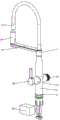
FIG. 1 is a disassembled structural schematic view of an embodiment of the present invention;
FIG. 2 is a schematic rear perspective view of an embodiment of the present invention;
FIG. 3 is a schematic perspective view of a front view according to an embodiment of the present invention;
FIG. 4 is a schematic rear view of a cross-sectional structure according to an embodiment of the present invention;
fig. 5 is a schematic left-view cross-sectional structure diagram according to an embodiment of the invention.
Wherein the figures include the following reference numerals:
the device comprises a base 1, a main body 2, an inner main body 3, a first valve core 4, a second valve core 5, a water outlet nozzle friction ring 6, a water outlet nozzle 7, a water outlet nozzle lower friction ring 8, an O-shaped ring 9, a glass panel 10, a bushing 11, a hose connector 12, a bent pipe 13, a drawing shower head 14, a bubbler set 15, a hand wheel 16, a hand wheel cover 17, a gasket 18, a fixed seat 19, a flat head screw 20, a cushion ring 21, a PE pipe 22, an inner hexagonal jackscrew 23, a bubbler seat 24, a decorative cover 25, a handle 26, a hand wheel friction ring 27, a hose 28 and a control box 29.
Detailed Description
The technical solutions in the embodiments of the present invention will be clearly and completely described below with reference to the drawings in the embodiments of the present invention, and it is obvious that the described embodiments are only a part of the embodiments of the present invention, and not all of the embodiments. The following description of at least one exemplary embodiment is merely illustrative in nature and is in no way intended to limit the invention, its application, or uses.
To maintain the following description of the embodiments of the present invention clear and concise, a detailed description of known functions and known components of the invention have been omitted.
Referring to fig. 1-5, in the present embodiment, a foam kitchen faucet is provided, which includes a base 1 and a control box 29, wherein a main body 2 is installed on the upper side of the base 1, a water outlet nozzle 7 is installed on the upper side of the main body 2, a bubbler base 24 and a bushing 11 are installed inside the water outlet nozzle 7, a bubbler set 15 is installed on the upper side of the bubbler base 24, a bent pipe 13 is installed on the upper side of the water outlet nozzle 7, and a pull-out shower head 14 is installed at one end of the bent pipe 13;
the base 1 is internally provided with an inner body 3 and a hose 28, one end of the hose 28 is connected to one side of a control box 29, and the other end of the hose 28 is connected to one side of the bubbler base 24.
The application of one aspect of the embodiment is as follows: the faucet is a dual-function kitchen faucet, the faucet is controlled to discharge water through the bidirectional valve core, normal domestic water and foam cleaning water can be used, the faucet is installed in a water tank of a kitchen, when the normal domestic water is used, the right handle 26 is firstly unscrewed, when cold and hot water enters through the inlet of the inner main body 3, the cold and hot water enters the PE pipe 22 after being mixed through the second valve core 5, and the cold and hot water passes through the bent pipe 13, is connected with the silica gel pipe group and then is discharged through the drawing shower head 14.
When foam cleaning water is needed, namely the hand wheel 16 is rotated forwards, the first valve core 4 serves as a control valve of a foam water channel, the foam water mixing control box 29 is connected with the hose 28, foam water passes through the water outlet nozzle 7 from the hose 28, and finally foam water is discharged from the bubbler 15.
Through the effect of the control box 29, the washing liquid and the water are conveniently mixed, and then the mixture forms the foam water, through the effect of the hose 28, the foam water after the mixture is conveniently conveyed to the inside of the water outlet nozzle 7, and then the mixed foam water flows out from the bubbler set 15, through the effect of the first valve core 4 and the second valve core 5, the outflow of the tap water and the foam water is conveniently switched, through the effect of the pull shower head 14, the adjustment of the spraying angle is convenient when the tap water is required to be sprayed, the life experience of consumers is improved through the device, the mechanical operation of extruding the liquid in the daily kitchen washing is reduced, the foam water is automatically mixed through the foam water mixing control box 29, the foam water can be easily switched to use the washing kitchenware, the water path is separately designed, the water quality cannot be influenced, meanwhile, the device has compact integral structure and is simple and effective, low cost, simple operation and convenient use for consumers.
Referring to fig. 1, in the embodiment, a first valve core 4 is installed on a first side of a main body 2, a hand wheel 16 is rotatably fitted on one side of the first valve core 4, a hand wheel cover 17 is installed on one side of the hand wheel 16, a hand wheel friction ring 27 is arranged between the first valve core 4 and the hand wheel 16, and the hand wheel 16 is rotated to conveniently control the opening or closing of the first valve core 4, so as to conveniently control the spraying process of the foam water.
Referring to fig. 1, in the present embodiment, a second valve core 5 is installed on a second side of a main body 2, a handle 26 is installed on one side of the second valve core 5, a backing ring 21 is installed between the second valve core 5 and the handle 26, a decorative cover 25 is installed on an outer peripheral side of the backing ring 21, and the flow rate of tap water is conveniently controlled by breaking the handle 26.
Referring to fig. 1-5, a silicone tube set is disposed inside the elbow 13 of the present embodiment, the pull shower head 14 is connected to one end of the silicone tube set, an adjusting switch is disposed on one side of the pull shower head 14, so that tap water can be conducted into the silicone tube set from the flat head screw 20 under the action of the silicone tube set, and then the tap water enters the pull shower head 14, so that the pull shower head 14 can flush objects in the water pool, and the amount of water flow sprayed from the pull shower head 14 can be adjusted under the action of the adjusting switch.
Referring to fig. 1, a lower nozzle friction ring 8, an O-ring 9, and a nozzle friction ring 6 are sequentially disposed between the main body 2 and the nozzle 7, and the O-ring 9 is disposed between the lower nozzle friction ring 8 and the nozzle friction ring 6, so that the sealing performance between the nozzle 7 and the main body 2 is conveniently increased and the possibility of liquid leakage from the nozzle 7 and the main body 2 is reduced by the mutual combination of the lower nozzle friction ring 8, the O-ring 9, and the nozzle friction ring 6.
Referring to fig. 1, in the present embodiment, an inner hexagonal jackscrew 23 is disposed on an upper side of the faucet friction ring 6, a flat head screw 20 is disposed inside the inner hexagonal jackscrew 23, and a fixing seat 19 is disposed on an upper side of the flat head screw 20, so that the inner hexagonal jackscrew 23 can be conveniently fixed by the flat head screw 20.
Referring to fig. 1-5, in the present embodiment, a PE tube 22 is disposed inside a main body 2, the PE tube 22 penetrates through an outlet nozzle 7 located on an upper side of the main body 2, a gasket 18 and a hose connector 12 are disposed between an elbow 13 and the outlet nozzle 7, the hose connector 12 is located on an upper side of the gasket 18, a glass panel 10 is disposed on an upper side of the outlet nozzle 7, openings corresponding to a bushing 11 and the PE tube 22 are sequentially formed inside the glass panel 10, the hose connector 12 and the PE tube 22 are conveniently connected together through the hose connector 12 and the PE tube 22, and the sealing performance between the hose connector 12 and the PE tube 22 is conveniently increased through an effect of a lower friction ring 8 of the outlet nozzle.
The above embodiments may be combined with each other.
It should be noted that in the description of the present specification, descriptions such as "first", "second", etc. are only used for distinguishing features, and do not have an actual order or meaning, and the present application is not limited thereto.
In the description herein, references to the description of "one embodiment," "an example," "a specific example" or the like are intended to mean that a particular feature, structure, material, or characteristic described in connection with the embodiment or example is included in at least one embodiment or example of the invention. In this specification, the schematic representations of the terms used above do not necessarily refer to the same embodiment or example. Furthermore, the particular features, structures, materials, or characteristics described may be combined in any suitable manner in any one or more embodiments or examples.
The preferred embodiments of the invention disclosed above are intended to be illustrative only. The preferred embodiments are not intended to be exhaustive or to limit the invention to the precise embodiments disclosed. Obviously, many modifications and variations are possible in light of the above teaching. The embodiments were chosen and described in order to best explain the principles of the invention and the practical application, to thereby enable others skilled in the art to best utilize the invention. The invention is limited only by the claims and their full scope and equivalents.
Claims (10)
1. A foam kitchen faucet, comprising: the device comprises a base (1) and a control box (29), wherein the main body (2) is arranged on the upper side of the base (1), a water outlet nozzle (7) is arranged on the upper side of the main body (2), a bubbler base (24) and a lining (11) are arranged inside the water outlet nozzle (7), a bubbler group (15) is arranged on the upper side of the bubbler base (24), a bent pipe (13) is arranged on the upper side of the water outlet nozzle (7), and a drawing shower head (14) is arranged at one end of the bent pipe (13);
an inner main body (3) and a hose (28) are arranged inside the base (1), one end of the hose (28) is connected to one side of the control box (29), and the other end of the hose (28) is connected to one side of the bubbler base (24).
2. The foam kitchen faucet of claim 1, wherein a first valve core (4) is mounted on a first side of the main body (2), a hand wheel (16) is rotatably fitted on one side of the first valve core (4), a hand wheel cover (17) is mounted on one side of the hand wheel (16), and a hand wheel friction ring (27) is disposed between the first valve core (4) and the hand wheel (16).
3. The kitchen faucet of claim 2, wherein the second side of the main body (2) is provided with a second valve core (5), one side of the second valve core (5) is provided with a handle (26), a backing ring (21) is arranged between the second valve core (5) and the handle (26), and the outer periphery of the backing ring (21) is provided with a decorative cover (25).
4. A kitchen faucet according to claim 3, characterized in that a lower nozzle friction ring (8), an O-ring (9) and a nozzle friction ring (6) are arranged between the main body (2) and the nozzle (7), and the O-ring (9) is arranged between the lower nozzle friction ring (8) and the nozzle friction ring (6).
5. A kitchen tap according to claim 4, characterised in that the body (2) is provided with a PE tube (22) inside, and that the PE tube (22) extends through the inside of the spout (7) on the upper side of the body (2).
6. A kitchen faucet according to claim 5, characterized in that a gasket (18), a hose connector (12) are provided between the elbow (13) and the spout (7), and the hose connector (12) is located on the upper side of the gasket (18).
7. A kitchen faucet of foam according to claim 6, characterized in that the upper side of the spout (7) is provided with a glass panel (10), and the inside of the glass panel (10) is provided with openings corresponding to the bushing (11) and the PE tube (22) in sequence.
8. A kitchen faucet according to claim 1, characterized in that the elbow (13) is internally provided with a silicone tube set, the pull-out shower head (14) being connected to one end of the silicone tube set.
9. Kitchen faucet according to claim 8, characterized in that the adjustment switch is provided on one side of the pull-out shower head (14).
10. A kitchen faucet of foam according to claim 1, characterized in that the upper side of the faucet friction ring (6) is provided with an inner hexagonal jackscrew (23), a grub screw (20) is arranged inside the inner hexagonal jackscrew (23), and the upper side of the grub screw (20) is provided with a fixing seat (19).
Priority Applications (1)
| Application Number | Priority Date | Filing Date | Title |
|---|---|---|---|
| CN202111189820.6A CN113898764B (en) | 2021-10-13 | 2021-10-13 | Foam kitchen tap |
Applications Claiming Priority (1)
| Application Number | Priority Date | Filing Date | Title |
|---|---|---|---|
| CN202111189820.6A CN113898764B (en) | 2021-10-13 | 2021-10-13 | Foam kitchen tap |
Publications (2)
| Publication Number | Publication Date |
|---|---|
| CN113898764A true CN113898764A (en) | 2022-01-07 |
| CN113898764B CN113898764B (en) | 2023-12-22 |
Family
ID=79191814
Family Applications (1)
| Application Number | Title | Priority Date | Filing Date |
|---|---|---|---|
| CN202111189820.6A Active CN113898764B (en) | 2021-10-13 | 2021-10-13 | Foam kitchen tap |
Country Status (1)
| Country | Link |
|---|---|
| CN (1) | CN113898764B (en) |
Citations (5)
| Publication number | Priority date | Publication date | Assignee | Title |
|---|---|---|---|---|
| EP1154083A1 (en) * | 2000-05-08 | 2001-11-14 | Gessi S.p.A. | Kitchen mixer tap with two independent rotating mouths for separate supply of two different types of water |
| CN102679036A (en) * | 2012-05-22 | 2012-09-19 | 周剑冰 | Water faucet for automatic power generation and ozone gas supply |
| CN104964056A (en) * | 2015-06-30 | 2015-10-07 | 开平市水口镇初升卫浴店 | Kitchen faucet |
| CN208967161U (en) * | 2018-10-31 | 2019-06-11 | 温州市多耐宝卫浴有限公司 | A kind of Kitchen tap |
| CN112814087A (en) * | 2021-03-04 | 2021-05-18 | 何仁熙 | Water tap for washing dishes |
-
2021
- 2021-10-13 CN CN202111189820.6A patent/CN113898764B/en active Active
Patent Citations (5)
| Publication number | Priority date | Publication date | Assignee | Title |
|---|---|---|---|---|
| EP1154083A1 (en) * | 2000-05-08 | 2001-11-14 | Gessi S.p.A. | Kitchen mixer tap with two independent rotating mouths for separate supply of two different types of water |
| CN102679036A (en) * | 2012-05-22 | 2012-09-19 | 周剑冰 | Water faucet for automatic power generation and ozone gas supply |
| CN104964056A (en) * | 2015-06-30 | 2015-10-07 | 开平市水口镇初升卫浴店 | Kitchen faucet |
| CN208967161U (en) * | 2018-10-31 | 2019-06-11 | 温州市多耐宝卫浴有限公司 | A kind of Kitchen tap |
| CN112814087A (en) * | 2021-03-04 | 2021-05-18 | 何仁熙 | Water tap for washing dishes |
Also Published As
| Publication number | Publication date |
|---|---|
| CN113898764B (en) | 2023-12-22 |
Similar Documents
| Publication | Publication Date | Title |
|---|---|---|
| CN107387816A (en) | A kind of discharge mechanism for possessing two kinds of water exit modes of filter water and light water | |
| CN107218415B (en) | Multifunctional multi-runner drinking water tap | |
| CN113898764A (en) | Foam kitchen tap | |
| CN209826470U (en) | Shower capable of removing residual water | |
| CN220228047U (en) | Tap with detergent structure | |
| WO2020165580A1 (en) | Multifunction tap | |
| CN218992449U (en) | Multifunctional kitchen faucet | |
| CN212801803U (en) | Waterway system of shower | |
| CN220910545U (en) | Kitchen tap with water purification function | |
| US20220112701A1 (en) | Water output device | |
| CN208518023U (en) | A kind of double water outlet Kitchen taps with spray gun | |
| CN218713602U (en) | Washbasin tap with soap dispenser | |
| CN211175485U (en) | Mixed water outlet faucet assembly | |
| CN219159610U (en) | Novel pull basin tap with waterfall water outlet | |
| CN217736408U (en) | Tap | |
| CN217232077U (en) | Washing basin | |
| CN220452832U (en) | Plastic inner core and faucet | |
| CN216742992U (en) | Integrated valve faucet capable of communicating purified water and tap water | |
| JP2547734Y2 (en) | Water heater | |
| CN209610970U (en) | A kind of three flap spray gun Tap for bathtub | |
| CN210687082U (en) | Water mixing valve and shower and faucet using same | |
| KR20090005756A (en) | Functional faucet | |
| CN218000496U (en) | Multifunctional tap | |
| CN220202850U (en) | Multifunctional water outlet device and bathroom cabinet | |
| CN111910722B (en) | Intelligent closestool |
Legal Events
| Date | Code | Title | Description |
|---|---|---|---|
| PB01 | Publication | ||
| PB01 | Publication | ||
| SE01 | Entry into force of request for substantive examination | ||
| SE01 | Entry into force of request for substantive examination | ||
| TA01 | Transfer of patent application right |
Effective date of registration: 20230524 Address after: 510000, 5th Floor, No. 41 Yingbin Road, Shangjiao Village, Luopu Street, Panyu District, Guangzhou City, Guangdong Province (Location: 508 Shop) Applicant after: Guangzhou Songbai Industrial Design Co.,Ltd. Address before: 528000 No. 405, floor 4, building 1, West District, green island Plaza, No. 129, Jihua West Road, Nanzhuang Town, Chancheng District, Foshan City, Guangdong Province (residence declaration) Applicant before: Foshan Zhizhe Technology Co.,Ltd. |
|
| TA01 | Transfer of patent application right | ||
| GR01 | Patent grant | ||
| GR01 | Patent grant |