EP3246252A1 - Button assembly for seat position control - Google Patents
Button assembly for seat position control Download PDFInfo
- Publication number
- EP3246252A1 EP3246252A1 EP17169026.6A EP17169026A EP3246252A1 EP 3246252 A1 EP3246252 A1 EP 3246252A1 EP 17169026 A EP17169026 A EP 17169026A EP 3246252 A1 EP3246252 A1 EP 3246252A1
- Authority
- EP
- European Patent Office
- Prior art keywords
- button
- seat panel
- button assembly
- flexible
- opening
- Prior art date
- Legal status (The legal status is an assumption and is not a legal conclusion. Google has not performed a legal analysis and makes no representation as to the accuracy of the status listed.)
- Granted
Links
Images

Classifications
-
- B—PERFORMING OPERATIONS; TRANSPORTING
- B60—VEHICLES IN GENERAL
- B60N—SEATS SPECIALLY ADAPTED FOR VEHICLES; VEHICLE PASSENGER ACCOMMODATION NOT OTHERWISE PROVIDED FOR
- B60N2/00—Seats specially adapted for vehicles; Arrangement or mounting of seats in vehicles
- B60N2/02—Seats specially adapted for vehicles; Arrangement or mounting of seats in vehicles the seat or part thereof being movable, e.g. adjustable
- B60N2/0224—Non-manual adjustments, e.g. with electrical operation
- B60N2/0226—User interfaces specially adapted for seat adjustment
- B60N2/0228—Hand-activated mechanical switches
-
- A—HUMAN NECESSITIES
- A47—FURNITURE; DOMESTIC ARTICLES OR APPLIANCES; COFFEE MILLS; SPICE MILLS; SUCTION CLEANERS IN GENERAL
- A47C—CHAIRS; SOFAS; BEDS
- A47C1/00—Chairs adapted for special purposes
- A47C1/02—Reclining or easy chairs
-
- B—PERFORMING OPERATIONS; TRANSPORTING
- B60—VEHICLES IN GENERAL
- B60N—SEATS SPECIALLY ADAPTED FOR VEHICLES; VEHICLE PASSENGER ACCOMMODATION NOT OTHERWISE PROVIDED FOR
- B60N2/00—Seats specially adapted for vehicles; Arrangement or mounting of seats in vehicles
- B60N2/02—Seats specially adapted for vehicles; Arrangement or mounting of seats in vehicles the seat or part thereof being movable, e.g. adjustable
-
- B—PERFORMING OPERATIONS; TRANSPORTING
- B64—AIRCRAFT; AVIATION; COSMONAUTICS
- B64D—EQUIPMENT FOR FITTING IN OR TO AIRCRAFT; FLIGHT SUITS; PARACHUTES; ARRANGEMENT OR MOUNTING OF POWER PLANTS OR PROPULSION TRANSMISSIONS IN AIRCRAFT
- B64D11/00—Passenger or crew accommodation; Flight-deck installations not otherwise provided for
- B64D11/06—Arrangements of seats, or adaptations or details specially adapted for aircraft seats
- B64D11/0639—Arrangements of seats, or adaptations or details specially adapted for aircraft seats with features for adjustment or converting of seats
- B64D11/064—Adjustable inclination or position of seats
-
- F—MECHANICAL ENGINEERING; LIGHTING; HEATING; WEAPONS; BLASTING
- F16—ENGINEERING ELEMENTS AND UNITS; GENERAL MEASURES FOR PRODUCING AND MAINTAINING EFFECTIVE FUNCTIONING OF MACHINES OR INSTALLATIONS; THERMAL INSULATION IN GENERAL
- F16C—SHAFTS; FLEXIBLE SHAFTS; ELEMENTS OR CRANKSHAFT MECHANISMS; ROTARY BODIES OTHER THAN GEARING ELEMENTS; BEARINGS
- F16C1/00—Flexible shafts; Mechanical means for transmitting movement in a flexible sheathing
- F16C1/10—Means for transmitting linear movement in a flexible sheathing, e.g. "Bowden-mechanisms"
- F16C1/102—Arrangements to mount end fittings of the sheathings to support walls or brackets
-
- F—MECHANICAL ENGINEERING; LIGHTING; HEATING; WEAPONS; BLASTING
- F16—ENGINEERING ELEMENTS AND UNITS; GENERAL MEASURES FOR PRODUCING AND MAINTAINING EFFECTIVE FUNCTIONING OF MACHINES OR INSTALLATIONS; THERMAL INSULATION IN GENERAL
- F16C—SHAFTS; FLEXIBLE SHAFTS; ELEMENTS OR CRANKSHAFT MECHANISMS; ROTARY BODIES OTHER THAN GEARING ELEMENTS; BEARINGS
- F16C1/00—Flexible shafts; Mechanical means for transmitting movement in a flexible sheathing
- F16C1/10—Means for transmitting linear movement in a flexible sheathing, e.g. "Bowden-mechanisms"
- F16C1/12—Arrangements for transmitting movement to or from the flexible member
-
- G—PHYSICS
- G05—CONTROLLING; REGULATING
- G05G—CONTROL DEVICES OR SYSTEMS INSOFAR AS CHARACTERISED BY MECHANICAL FEATURES ONLY
- G05G1/00—Controlling members, e.g. knobs or handles; Assemblies or arrangements thereof; Indicating position of controlling members
- G05G1/02—Controlling members for hand actuation by linear movement, e.g. push buttons
-
- H—ELECTRICITY
- H02—GENERATION; CONVERSION OR DISTRIBUTION OF ELECTRIC POWER
- H02B—BOARDS, SUBSTATIONS OR SWITCHING ARRANGEMENTS FOR THE SUPPLY OR DISTRIBUTION OF ELECTRIC POWER
- H02B1/00—Frameworks, boards, panels, desks, casings; Details of substations or switching arrangements
- H02B1/015—Boards, panels, desks; Parts thereof or accessories therefor
- H02B1/04—Mounting thereon of switches or of other devices in general, the switch or device having, or being without, casing
- H02B1/044—Mounting through openings
- H02B1/048—Snap mounting
Definitions
- This application generally relates to the field of mechanical actuators that are used, for example, in connection with reclining seats and related systems, and more particular to button assemblies for controlling positions of such seats.
- Reclining seats or chairs are commonly deployed in various industries, including, for example, the airline industry.
- hydraulic or mechanical actuators are used to allow for positioning such seats in various positions.
- the actuators enable the seat to assume an upright position as well as a continuous range of reclined positions.
- at least one control button may be provided.
- the control buttons may be used to engage, for example, an activator cable for the seat system, wherein the button assemblies may be deployed within armrests or other seat panels.
- prior art button assemblies In terms of manufacture, prior art button assemblies normally require the installer to hold the button assembly from the underside while installing a button housing or sleeve on the outside in order to lock the button assembly into the panel. This may be difficult, particularly if space is limited around the button assembly. Therefore, a general need exists for enhanced button assemblies for controlling the position of reclining seats, which are also capable of being quickly and easily installed from the outside of the panel.
- a button assembly for controlling a seat position and mounting on a seat panel.
- the button assemblies may have a button housing configured to position over edges of an opening in the seat panel and opposite an outer surface thereof
- One or more flexible retaining members may be attached to a portion of the button housing, in which the one or more flexible retaining members are configured to compress when advanced through the opening in the seat panel and expand therein positioned opposite an inner surface thereof when the assembly is seated.
- the one or more flexible retaining members include at least one flexible finger extending outward from the button housing.
- the flexible finger may be configured to expand into the seat panel with ends of the flexible finger positioned opposite the inner surface of the seat panel. A mechanical force of the ends of the flexible finger against the inner surface of the seat panel may inhibit removal of the button assembly from the seat panel.
- the one or more flexible retaining members include at least one flexible reflexed portion, the flexible reflexed portion bowing outward from the button assembly.
- the flexible reflexed portion may be configured to compress through the opening in the seat panel and expand into the seat panel with middle portions of the flexible reflexed portion positioned opposite the inner surface of the seat panel. A frictional force of the middle portion of the flexible reflexed portion against the edge of opening in the seat panel may inhibit removal of the button assembly from the seat panel.
- buttons assembly in ease and reliability of manufacture relative to a seat panel.
- the button assemblies can be fabricated without requiring additional materials or cost and in which the assemblies can be assembled within a space constrained environment and in a simpler manner due to the ability for the button assembly to snap into the seat panel without having to be held in place during a complex mounting operation.
- the present disclosure provides, in part, button assemblies for controlling seat positions, for use in, for example, airline seats.
- airline seats may include positioning features for passenger comfort during travel.
- seat backs may recline
- foot rests may extend outward
- lumbar supports may be provided, etc.
- Space around the button assembly may be limited, such as in a seat arm. This limitation in space makes it difficult to install a button assembly, particularly if the button assembly must be held from the underside for purposes of installation.
- the present disclosure provides button assemblies, such as snap-in button assemblies that are capable of being mounted on a seat panel, such as an armrest or a sidewall quickly and easily from the outside of the panel only.
- the button assemblies disclosed herein may be mounted onto the seat panel or armrest without having to hold the button assembly from the underside of the panel where space is limited.
- the present button assemblies include one or more flexible retaining members which compress through a seat panel opening during installation and expand to a nominal position once the button assembly is advanced through the opening within the seat panel.
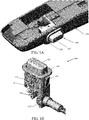
- FIGS. 1A-1E depict a button assembly 100 in accordance with a first embodiment.
- the button assembly 100 is shown in a mounted position relative to a seat panel 140 (partially shown), the assembly 100 including an actuable button 105 which is used selectively by the occupant of the seat to control a position of the seat (not shown), as described in detail herein.
- FIGS. 1B-1E provide various views of the button assembly 100, in accordance with FIG. 1A .
- the button assembly 100 according to this embodiment includes an actuable button 105, a button housing 125 and one or more flexible retaining members 120, as well as an outer cap or cover portion 110.
- the button assembly 100 includes a control cable activator 130 and a control cable holder 135, attached to a lower end of the button housing 125.
- the control cable activator 130 includes a first engagement arm 131 that is initially disposed in relation to a lower shaft-like portion 106 of the actuable button 105 and a second engagement arm 132 having a through opening that supports a portion of a control cable 150, the latter being further housed within a control cable sleeve 151.
- pressing the actuable button 105 will cause the lower portion 106 of the button 105 to contact the first engagement arm 131 of the control cable activator 130, the latter being pivotally attached by means of a pinned bracket 126 to the button housing 125 at a pivot point A.
- the control cable activator 130 rotates clockwise, causing the supported control cable 150 to move from a first position to a second position (to the left as viewed in FIG. 1D and upward as shown in FIG. 1E ).
- the control cable sleeve 151 is held in place, preferably by the control cable holder 135 during such movement.
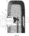
- FIG. 1E is a cross-sectional view of the button assembly 100 as mounted in an opening 145 in seat panel 140, in accordance with aspects set forth herein.
- a flexible retaining member 120 is provided on opposing lateral sides of the button housing 125, each flexible retaining member 120 being defined by a wedge shaped configuration including a cantilevered end that extends outwardly relative to the exterior surface of the button housing 125.
- the retaining members nominally assume a outwardly flexed position in which each member is configured to inwardly flex toward the outer surface of the button housing 125 when acted upon by a compressive force.
- the inserted end of the one or more flexible retaining members 120 Upon insertion of the button assembly 100 into the seat panel 140 and when passing the edge of the opening 145, the inserted end of the one or more flexible retaining members 120 has a narrower width than the outer end, so that the members 120 may readily pass through the opening 145 and into the seat panel 140.
- the one or more flexible retaining member 120 flex inward against the compressive force of the edges of the opening 145, allowing entry into the defined opening 145. Once the widest portion of the flexible retaining members 120 clears the opening 145, the flexible retaining members 120 are caused to bend outward, thereby returning the members to their original cantilevered shape and position due to the cessation of the compressive force.
- the cantilevered ends of flexible retaining members 120 are positioned opposite an inner surface 141 of the seat panel 140, and beyond the outer edge of the opening 145. This cantilevered positioning of the one of more flexible retaining members 120 against the inner surface 141 restricts removal of the button assembly 100 from the seat panel 140.
- the outer cover or cap portion 110 of the button housing 125 defines a shoulder that covers an edge surface of the opening 145 in which the upper cover or cap portion 110 has an outer dimension (L1) relative to the width (L2) of the opening 145.
- the upper cover or cap portion 110 of the button housing 125 is therefore positioned over the edge of the opening 145 and against the outer surface 142 of the seat panel 140.
- the number of flexible retaining members 120 may vary, depending on the mechanical strength desired, the materials employed, the dimensions of the parts, etc.
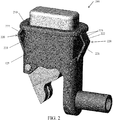
- FIG. 2 depicts a button assembly 200, in accordance with another embodiment.
- This assembly 200 includes a pair of flexible retaining members 220 that are defined by a first cantilevered portion 221 extending outwardly from an exterior lateral wall surface of the housing 125 at an acute angle and a second reflexed portion 222 that inwardly extends from the cantilevered portion 221 toward the bottom surface of a shoulder formed by the upper cover or cap portion 210 of the assembly 200.
- each of the retaining members 220 assumes a substantial "V-shape.” After insertion of the button assembly 200 into an opening defined in the seat panel (not shown in this view), the V-shaped retaining members 220 are caused to compress inwardly to permit assembly but in which the members are caused to expand outwardly and revert to their substantial "V-shape" once the members have cleared the opening into the seat panel. As in the prior described embodiment, the retaining members 220 prevent or inhibits removal of the seated assembly against the edges of the opening in the seat panel.
- the cantilevered and reflexed portions 221, 222 are configured to move inwardly or compress upon insertion of the button assembly 200 into the opening in a seat panel (not shown) and then expand outwardly within the seat panel in the position shown in Fig. 2 .
- Frictional forces between the edge of the opening in a seat panel and each retaining member 220 may further be increased by the addition of ribs 223, to further inhibit removal of the button assembly 200 after insertion into a seat panel.
Landscapes
- Engineering & Computer Science (AREA)
- General Engineering & Computer Science (AREA)
- Aviation & Aerospace Engineering (AREA)
- Mechanical Engineering (AREA)
- Health & Medical Sciences (AREA)
- Oral & Maxillofacial Surgery (AREA)
- Power Engineering (AREA)
- Transportation (AREA)
- Physics & Mathematics (AREA)
- General Physics & Mathematics (AREA)
- Automation & Control Theory (AREA)
- Dentistry (AREA)
- General Health & Medical Sciences (AREA)
- Human Computer Interaction (AREA)
- Seats For Vehicles (AREA)
Abstract
Description
- This application generally relates to the field of mechanical actuators that are used, for example, in connection with reclining seats and related systems, and more particular to button assemblies for controlling positions of such seats.
- Reclining seats or chairs are commonly deployed in various industries, including, for example, the airline industry. Typically, hydraulic or mechanical actuators are used to allow for positioning such seats in various positions. For example, the actuators enable the seat to assume an upright position as well as a continuous range of reclined positions. In order to control the positions of these seats, at least one control button may be provided. The control buttons may be used to engage, for example, an activator cable for the seat system, wherein the button assemblies may be deployed within armrests or other seat panels.
- In terms of manufacture, prior art button assemblies normally require the installer to hold the button assembly from the underside while installing a button housing or sleeve on the outside in order to lock the button assembly into the panel. This may be difficult, particularly if space is limited around the button assembly. Therefore, a general need exists for enhanced button assemblies for controlling the position of reclining seats, which are also capable of being quickly and easily installed from the outside of the panel.
- Therefore and according to one aspect, there is provided a button assembly for controlling a seat position and mounting on a seat panel. The button assemblies may have a button housing configured to position over edges of an opening in the seat panel and opposite an outer surface thereof One or more flexible retaining members may be attached to a portion of the button housing, in which the one or more flexible retaining members are configured to compress when advanced through the opening in the seat panel and expand therein positioned opposite an inner surface thereof when the assembly is seated.
- In another aspect, the one or more flexible retaining members include at least one flexible finger extending outward from the button housing. The flexible finger may be configured to expand into the seat panel with ends of the flexible finger positioned opposite the inner surface of the seat panel. A mechanical force of the ends of the flexible finger against the inner surface of the seat panel may inhibit removal of the button assembly from the seat panel.
- In a further aspect, the one or more flexible retaining members include at least one flexible reflexed portion, the flexible reflexed portion bowing outward from the button assembly. The flexible reflexed portion may be configured to compress through the opening in the seat panel and expand into the seat panel with middle portions of the flexible reflexed portion positioned opposite the inner surface of the seat panel. A frictional force of the middle portion of the flexible reflexed portion against the edge of opening in the seat panel may inhibit removal of the button assembly from the seat panel.
- An advantage realized by the herein described button assembly is that in ease and reliability of manufacture relative to a seat panel. The button assemblies can be fabricated without requiring additional materials or cost and in which the assemblies can be assembled within a space constrained environment and in a simpler manner due to the ability for the button assembly to snap into the seat panel without having to be held in place during a complex mounting operation.
- These and other embodiments, features and advantages will become apparent to those skilled in the art when taken with reference to the following more Detailed Description in conjunction with the accompanying drawings that are first briefly described.
- The accompanying drawings, which are incorporated herein and constitute part of this specification, illustrate presently preferred embodiments of the invention, and, together with the general description given above and the detailed description given below, serve to explain features of the invention (wherein like numerals represent like elements).
- FIG. 1A
- is a side perspective view of a button assembly in accordance with one embodiment as mounted in a seat arm panel of a seat, and in accordance with aspects set forth herein;
- FIG. 1B
- is a top perspective view of the button assembly of
FIG. 1A ; - FIG. 1C
- is an end view of the button assembly of
FIGS. 1A-1B ; - FIG. 1D
- is a side elevational view of the button assembly of
FIGS. 1A-1C ; - FIG. 1E
- is a side elevational view, shown in section, of the button assembly of
FIGS. 1A-1D shown in an assembled position in a seat panel; and - FIG. 2
- is a side perspective view of a button assembly in accordance with another embodiment.
- The following Detailed Description should be read with reference to the drawings, in which like elements in different drawings are identically numbered. The drawings, which are not necessarily to scale, depict selected embodiments and are not intended to limit the scope of the invention. The Detailed Description illustrates by way of example, not by way of limitation, the principles of the invention. This description will clearly enable one skilled in the art to make and use the invention, and describes several embodiments, adaptations, variations, alternatives and uses of the invention, including what is presently believed to be the best mode of carrying out the invention.
- The present disclosure provides, in part, button assemblies for controlling seat positions, for use in, for example, airline seats. By way of example, airline seats may include positioning features for passenger comfort during travel. For example, seat backs may recline, foot rests may extend outward, lumbar supports may be provided, etc. Space around the button assembly may be limited, such as in a seat arm. This limitation in space makes it difficult to install a button assembly, particularly if the button assembly must be held from the underside for purposes of installation. Advantageously, the present disclosure provides button assemblies, such as snap-in button assemblies that are capable of being mounted on a seat panel, such as an armrest or a sidewall quickly and easily from the outside of the panel only. By contrast with conventional button assemblies, the button assemblies disclosed herein may be mounted onto the seat panel or armrest without having to hold the button assembly from the underside of the panel where space is limited. For example, the present button assemblies include one or more flexible retaining members which compress through a seat panel opening during installation and expand to a nominal position once the button assembly is advanced through the opening within the seat panel.
-
FIGS. 1A-1E depict abutton assembly 100 in accordance with a first embodiment. With reference toFIG. 1A , thebutton assembly 100 is shown in a mounted position relative to a seat panel 140 (partially shown), theassembly 100 including anactuable button 105 which is used selectively by the occupant of the seat to control a position of the seat (not shown), as described in detail herein. -
FIGS. 1B-1E provide various views of thebutton assembly 100, in accordance withFIG. 1A . Thebutton assembly 100 according to this embodiment includes anactuable button 105, abutton housing 125 and one or more flexible retainingmembers 120, as well as an outer cap orcover portion 110. - Further, the
button assembly 100 according to this depicted embodiment includes acontrol cable activator 130 and acontrol cable holder 135, attached to a lower end of thebutton housing 125. When installed and as best shown inFigs. 1C - 1E , thecontrol cable activator 130 includes afirst engagement arm 131 that is initially disposed in relation to a lower shaft-like portion 106 of theactuable button 105 and asecond engagement arm 132 having a through opening that supports a portion of acontrol cable 150, the latter being further housed within acontrol cable sleeve 151. In operation, pressing theactuable button 105 will cause thelower portion 106 of thebutton 105 to contact thefirst engagement arm 131 of thecontrol cable activator 130, the latter being pivotally attached by means of a pinnedbracket 126 to thebutton housing 125 at a pivot point A. When engaged and according to this embodiment, thecontrol cable activator 130 rotates clockwise, causing the supportedcontrol cable 150 to move from a first position to a second position (to the left as viewed inFIG. 1D and upward as shown inFIG. 1E ). Thecontrol cable sleeve 151 is held in place, preferably by thecontrol cable holder 135 during such movement. -
FIG. 1E is a cross-sectional view of thebutton assembly 100 as mounted in anopening 145 inseat panel 140, in accordance with aspects set forth herein. According to this embodiment, aflexible retaining member 120 is provided on opposing lateral sides of thebutton housing 125, each flexible retainingmember 120 being defined by a wedge shaped configuration including a cantilevered end that extends outwardly relative to the exterior surface of thebutton housing 125. When fabricated, the retaining members nominally assume a outwardly flexed position in which each member is configured to inwardly flex toward the outer surface of thebutton housing 125 when acted upon by a compressive force. - Upon insertion of the
button assembly 100 into theseat panel 140 and when passing the edge of theopening 145, the inserted end of the one or more flexible retainingmembers 120 has a narrower width than the outer end, so that themembers 120 may readily pass through theopening 145 and into theseat panel 140. As thebutton assembly 100 progresses into theopening 145, the one or more flexible retainingmember 120 flex inward against the compressive force of the edges of theopening 145, allowing entry into the definedopening 145. Once the widest portion of theflexible retaining members 120 clears theopening 145, theflexible retaining members 120 are caused to bend outward, thereby returning the members to their original cantilevered shape and position due to the cessation of the compressive force. In the nominal seated position of thebutton assembly 100 within theseat panel 140 depicted inFIG. 1E , the cantilevered ends offlexible retaining members 120 are positioned opposite aninner surface 141 of theseat panel 140, and beyond the outer edge of theopening 145. This cantilevered positioning of the one of more flexible retainingmembers 120 against theinner surface 141 restricts removal of thebutton assembly 100 from theseat panel 140. - Still referring to
Fig. 1E and when thebutton assembly 100 is seated, the outer cover orcap portion 110 of thebutton housing 125 defines a shoulder that covers an edge surface of theopening 145 in which the upper cover orcap portion 110 has an outer dimension (L1) relative to the width (L2) of theopening 145. In such a case, the upper cover orcap portion 110 of thebutton housing 125 is therefore positioned over the edge of theopening 145 and against theouter surface 142 of theseat panel 140. As previously noted, the number offlexible retaining members 120 may vary, depending on the mechanical strength desired, the materials employed, the dimensions of the parts, etc. - It will be understood that other configurations are possible. For example,
FIG. 2 depicts abutton assembly 200, in accordance with another embodiment. Thisassembly 200 includes a pair offlexible retaining members 220 that are defined by a first cantileveredportion 221 extending outwardly from an exterior lateral wall surface of thehousing 125 at an acute angle and a secondreflexed portion 222 that inwardly extends from the cantileveredportion 221 toward the bottom surface of a shoulder formed by the upper cover orcap portion 210 of theassembly 200. According to this specific embodiment, each of the retainingmembers 220 assumes a substantial "V-shape." After insertion of thebutton assembly 200 into an opening defined in the seat panel (not shown in this view), the V-shaped retainingmembers 220 are caused to compress inwardly to permit assembly but in which the members are caused to expand outwardly and revert to their substantial "V-shape" once the members have cleared the opening into the seat panel. As in the prior described embodiment, the retainingmembers 220 prevent or inhibits removal of the seated assembly against the edges of the opening in the seat panel. - In operation, the cantilevered and
reflexed portions button assembly 200 into the opening in a seat panel (not shown) and then expand outwardly within the seat panel in the position shown inFig. 2 . Frictional forces between the edge of the opening in a seat panel and each retainingmember 220 may further be increased by the addition ofribs 223, to further inhibit removal of thebutton assembly 200 after insertion into a seat panel. - While the invention has been described in terms of particular variations and illustrative figures, those of ordinary skill in the art will recognize that the invention is not limited to the variations or figures described. In addition, where methods and steps described above indicate certain events occurring in certain order, those of ordinary skill in the art will recognize that the ordering of certain steps may be modified and that such modifications are in accordance with the variations of the invention. Additionally, certain of the steps may be performed concurrently in a parallel process when possible, as well as performed sequentially as described above. Therefore, to the extent there are variations of the invention, which are within the spirit of the disclosure or equivalent to the inventions found in the claims, it is the intent that this patent will cover those variations as well.
Claims (10)
- A button assembly (100) for controlling a seat position and mounting on a seat panel (140), the button assembly comprising:a button housing (125), the button housing (125) being configured to position over edges of an opening (145) in the seat panel (140) and opposite an outer surface (142) of the seat panel (140); andone or more flexible retaining members (120) attached to a portion of the button housing (125), the one or more flexible retaining members (120) being configured to compress through the opening (145) in the seat panel (140) and expand therein positioned opposite an inner surface (141) thereof, wherein the one or more flexible retaining members (120) positioned opposite the inner surface (141) of the seat panel (140) and the button housing (125) positioned opposite the outer surface (142) of the seat panel (140) mount the button assembly (100) to the seat panel (140).
- The button assembly of claim 1, wherein the one or more flexible retaining members (120) comprise at least one flexible finger extending outward from the button housing (125), wherein the flexible finger is configured to expand into the seat panel (140) with ends of the flexible finger positioned opposite the inner surface (141) of the seat panel (140), and wherein a mechanical force of the ends of the flexible finger against the inner surface (141) of the seat panel (140) inhibits removal of the button assembly (100) from the seat panel (140).
- The button assembly of claim 2, wherein the flexible finger has a predetermined width differential between an expanded configuration and a compressed configuration, wherein the predetermined width differential of the flexible finger is selected for the end of the flexible finger in the expanded configuration to overlap an edge of the opening (145) in the seat panel (140).
- The button assembly of one of the preceding claims, wherein the one or more flexible retaining members (125) comprise at least one flexible reflexed portion (221), the flexible reflexed portion (221) bowing outward from the button assembly (100), wherein the flexible reflexed portion (221) is configured to compress through the opening (145) in the seat panel (140) and expand into the interior of the seat panel (140).
- The button assembly of one of the preceding claims, wherein the button housing (125) has a larger footprint than a footprint of the opening (145) in the seat panel (140), the larger footprint of the button housing (125) facilitating holding the button assembly (100) against the opening (145) in the seat panel (140).
- The button assembly of one of the preceding claims, wherein the one or more flexible retaining members (120) in a compressed position have a smaller footprint than a footprint of the opening (145) in the seat panel (140), the smaller footprint of the compressed flexible retaining members (120) facilitating insertion of the button assembly (100) into the seat panel (140).
- The button assembly of one of the preceding claims, wherein the one or more flexible retaining members (120) in an expanded position have a larger footprint than a footprint of the opening (145) in the seat panel (140), the larger footprint of the one or more flexible retaining members (120) facilitating holding the button assembly (100) against the opening (145) in the seat panel (140).
- The button assembly of one of the preceding claims, further comprising a button housing (125) and a button (105), wherein the button (105) is attached to one end of the button housing (125) and the one or more flexible retaining members (120) are attached to a middle portion of the button housing (125), wherein the button housing (125) and the button (105) are configured to fit through the opening (145) in the seat panel (140).
- The button assembly of one of the preceding claims, further comprising a control cable activator (130) attached to the other end of the button housing (125), the control cable activator (130) being connected to the button housing (125) at an axis (A), wherein the control cable activator (130) is configured to hold a control cable (150) and the button (105) is configured to rotate the control cable activator (130) about the axis (A) to facilitate movement of the control cable (150) from a first position to a second position.
- The button assembly of one of the preceding claims, further comprising a control cable holder (135) attached to the other end of the button housing (125) and opposite the control cable activator (130), wherein the control cable holder (135) facilitates securing the control cable (150) during the movement thereof from the first position to the second position.
Applications Claiming Priority (1)
| Application Number | Priority Date | Filing Date | Title |
|---|---|---|---|
| US15/156,373 US10173778B2 (en) | 2016-05-17 | 2016-05-17 | Button assembly for seat position control |
Publications (2)
| Publication Number | Publication Date |
|---|---|
| EP3246252A1 true EP3246252A1 (en) | 2017-11-22 |
| EP3246252B1 EP3246252B1 (en) | 2019-07-24 |
Family
ID=58668764
Family Applications (1)
| Application Number | Title | Priority Date | Filing Date |
|---|---|---|---|
| EP17169026.6A Active EP3246252B1 (en) | 2016-05-17 | 2017-05-02 | Button assembly for seat position control |
Country Status (3)
| Country | Link |
|---|---|
| US (2) | US10173778B2 (en) |
| EP (1) | EP3246252B1 (en) |
| BR (1) | BR102017010275A2 (en) |
Cited By (1)
| Publication number | Priority date | Publication date | Assignee | Title |
|---|---|---|---|---|
| WO2020205692A1 (en) | 2019-04-01 | 2020-10-08 | Haeco Americas, Inc. | Seat system having a rotary recline lever |
Families Citing this family (9)
| Publication number | Priority date | Publication date | Assignee | Title |
|---|---|---|---|---|
| WO2016133638A1 (en) * | 2015-02-20 | 2016-08-25 | Zodiac Seats Us Llc | Haptic system: recline activation control |
| JP6912607B2 (en) * | 2018-02-09 | 2021-08-04 | 株式会社オートネットワーク技術研究所 | Armrest |
| USD909172S1 (en) * | 2018-06-25 | 2021-02-02 | Rodstation Limited | Button |
| US12276367B2 (en) * | 2022-12-15 | 2025-04-15 | Itt Manufacturing Enterprises Llc | Flexible conduit for control cable having flame retardant outer sleeve |
| CN121057987A (en) * | 2023-05-23 | 2025-12-02 | Itt制造企业有限责任公司 | Button assembly with modular buttons and sleeves and an infinitely rotating cable outlet. |
| US20240400206A1 (en) * | 2023-06-01 | 2024-12-05 | B/E Aerospace, Inc. | Seat console with ergonomically positioned cable-actuated passenger control unit |
| US20250042552A1 (en) * | 2023-07-31 | 2025-02-06 | Textron Aviation, Inc. | Electronically Actuated Seat Recline Release |
| US12522361B2 (en) | 2023-08-03 | 2026-01-13 | B/E Aerospace, Inc. | Recline lockout device for aircraft seat |
| DE102024127007A1 (en) * | 2024-09-19 | 2026-03-19 | Recaro Aircraft Seating Gmbh & Co. Kg | Aircraft seat actuation device |
Citations (6)
| Publication number | Priority date | Publication date | Assignee | Title |
|---|---|---|---|---|
| US4159405A (en) * | 1977-05-25 | 1979-06-26 | General Electric Company | Push button arranged for mounting to a panel |
| US4515034A (en) * | 1980-06-09 | 1985-05-07 | P. L. Porter Co. | Control mechanism for hydraulic locking device |
| US5541569A (en) * | 1995-02-28 | 1996-07-30 | Jang; Huey J. | Switch having a circuit breaker |
| EP0796576A1 (en) * | 1996-03-21 | 1997-09-24 | P.L. Porter Company | Low profile push-Button Mechanical remote control |
| DE19650823C1 (en) * | 1996-12-07 | 1998-01-08 | Faure Bertrand Sitztech Gmbh | Security device for vehicle electrically powered front seat with backrest shell on frame |
| US5727675A (en) * | 1996-09-06 | 1998-03-17 | Eaton Corporation | Latching pushbutton switch assembly |
Family Cites Families (15)
| Publication number | Priority date | Publication date | Assignee | Title |
|---|---|---|---|---|
| US2605374A (en) * | 1949-08-31 | 1952-07-29 | Hugh W Batcheller | Electric switch for door jambs |
| US3213189A (en) * | 1963-04-02 | 1965-10-19 | United Carr Inc | Fastener cap |
| US4211905A (en) * | 1979-02-14 | 1980-07-08 | Stackpole Components Company | Slide switch assembly for mounting in a panel |
| US4715096A (en) * | 1986-07-10 | 1987-12-29 | Fleming Joseph A | Thermally actuated seat belt fastener |
| US5010780A (en) * | 1990-05-15 | 1991-04-30 | Plastic Industries, Inc. | Device for actuating a remotely positioned spring-biased latch |
| US5146056A (en) * | 1991-04-29 | 1992-09-08 | Kuczynski Robert A | Snap-in bracket for circuit breaker |
| US6132245A (en) * | 1998-05-04 | 2000-10-17 | The Whitaker Corporation | Electrical connector for a speaker cabinet |
| TW458353U (en) * | 1999-11-25 | 2001-10-01 | You Tsung Mou | Switching box structure |
| DE102004049435B4 (en) * | 2004-10-08 | 2006-11-16 | Zf Friedrichshafen Ag | Button with cable |
| TWM286989U (en) * | 2005-09-27 | 2006-02-01 | Joemex Electric Corp | Power switch protector |
| EP1870527B1 (en) * | 2006-06-20 | 2017-05-31 | Geberit International AG | Device for activating the outlet valve of a sanitary article. |
| EP2789262B1 (en) * | 2013-04-12 | 2018-06-13 | Logicdata Electronic&Software Entwicklungs GmbH | Adjustable seating furniture with hand-switch arrangement and assembly method for an adjustable seating furniture |
| US20180218850A1 (en) * | 2015-07-09 | 2018-08-02 | Vita-Mix Management Corporation | Multi-panel thickness mounting for switch |
| US10696191B2 (en) * | 2015-11-03 | 2020-06-30 | Safran Seats Usa Llc | Pull actuator release for reclining seats |
| TWI679663B (en) * | 2018-07-03 | 2019-12-11 | 易湘雲 | Thermally damaged power-off switch and socket having the switch |
-
2016
- 2016-05-17 US US15/156,373 patent/US10173778B2/en active Active
-
2017
- 2017-05-02 EP EP17169026.6A patent/EP3246252B1/en active Active
- 2017-05-16 BR BR102017010275-0A patent/BR102017010275A2/en not_active Application Discontinuation
-
2019
- 2019-01-07 US US16/241,052 patent/US10829223B2/en active Active
Patent Citations (6)
| Publication number | Priority date | Publication date | Assignee | Title |
|---|---|---|---|---|
| US4159405A (en) * | 1977-05-25 | 1979-06-26 | General Electric Company | Push button arranged for mounting to a panel |
| US4515034A (en) * | 1980-06-09 | 1985-05-07 | P. L. Porter Co. | Control mechanism for hydraulic locking device |
| US5541569A (en) * | 1995-02-28 | 1996-07-30 | Jang; Huey J. | Switch having a circuit breaker |
| EP0796576A1 (en) * | 1996-03-21 | 1997-09-24 | P.L. Porter Company | Low profile push-Button Mechanical remote control |
| US5727675A (en) * | 1996-09-06 | 1998-03-17 | Eaton Corporation | Latching pushbutton switch assembly |
| DE19650823C1 (en) * | 1996-12-07 | 1998-01-08 | Faure Bertrand Sitztech Gmbh | Security device for vehicle electrically powered front seat with backrest shell on frame |
Cited By (2)
| Publication number | Priority date | Publication date | Assignee | Title |
|---|---|---|---|---|
| WO2020205692A1 (en) | 2019-04-01 | 2020-10-08 | Haeco Americas, Inc. | Seat system having a rotary recline lever |
| EP3947149A4 (en) * | 2019-04-01 | 2022-12-07 | HAECO Americas, LLC | SEAT SYSTEM FEATURING A ROTATING TILT LEVER |
Also Published As
| Publication number | Publication date |
|---|---|
| US20190135439A1 (en) | 2019-05-09 |
| US10829223B2 (en) | 2020-11-10 |
| US10173778B2 (en) | 2019-01-08 |
| BR102017010275A2 (en) | 2017-12-05 |
| US20170334563A1 (en) | 2017-11-23 |
| EP3246252B1 (en) | 2019-07-24 |
Similar Documents
| Publication | Publication Date | Title |
|---|---|---|
| EP3246252A1 (en) | Button assembly for seat position control | |
| JP5688463B2 (en) | Headrest with two wing elements | |
| EP3863889B1 (en) | Vehicle seating | |
| EP3556253A1 (en) | Furniture member with foldable pawl and ratchet assembly | |
| US20120223564A1 (en) | Armrest Mounting Assembly and Misalignment Indicator | |
| EP2415630A2 (en) | Lifting mechanism of vehicle seat | |
| CN101523064A (en) | Cable connection structure | |
| EP4410594A1 (en) | Vehicle seat device | |
| JP4766116B2 (en) | Cable connection structure | |
| US20100013289A1 (en) | Vehicular seats | |
| CN110650658A (en) | Chair (Ref. TM. chair) | |
| JP6872127B2 (en) | Cup holder | |
| KR101628753B1 (en) | Seat for automobile having armrest | |
| KR102038933B1 (en) | Seat for an automobile | |
| KR102563449B1 (en) | Armrest device with level maintenance | |
| EP4385816A1 (en) | Reclining device for vehicle seat | |
| CN107968011A (en) | Input unit | |
| CN110636781A (en) | Chair | |
| KR102112109B1 (en) | Folding assembly of seat for vehicle | |
| CN112888595A (en) | Swivel mechanism for swiveling a seat in a motor vehicle | |
| KR102025620B1 (en) | Stepless Height Controlling Headrest | |
| KR101533933B1 (en) | Hinge apparatus for arm rest | |
| JP4992574B2 (en) | Cable connection structure | |
| JP2019083954A (en) | Lumber pad device | |
| JP4654986B2 (en) | Cable connection structure for vehicle seat |
Legal Events
| Date | Code | Title | Description |
|---|---|---|---|
| PUAI | Public reference made under article 153(3) epc to a published international application that has entered the european phase |
Free format text: ORIGINAL CODE: 0009012 |
|
| STAA | Information on the status of an ep patent application or granted ep patent |
Free format text: STATUS: THE APPLICATION HAS BEEN PUBLISHED |
|
| AK | Designated contracting states |
Kind code of ref document: A1 Designated state(s): AL AT BE BG CH CY CZ DE DK EE ES FI FR GB GR HR HU IE IS IT LI LT LU LV MC MK MT NL NO PL PT RO RS SE SI SK SM TR |
|
| AX | Request for extension of the european patent |
Extension state: BA ME |
|
| STAA | Information on the status of an ep patent application or granted ep patent |
Free format text: STATUS: REQUEST FOR EXAMINATION WAS MADE |
|
| 17P | Request for examination filed |
Effective date: 20180514 |
|
| RBV | Designated contracting states (corrected) |
Designated state(s): AL AT BE BG CH CY CZ DE DK EE ES FI FR GB GR HR HU IE IS IT LI LT LU LV MC MK MT NL NO PL PT RO RS SE SI SK SM TR |
|
| STAA | Information on the status of an ep patent application or granted ep patent |
Free format text: STATUS: EXAMINATION IS IN PROGRESS |
|
| 17Q | First examination report despatched |
Effective date: 20180910 |
|
| GRAP | Despatch of communication of intention to grant a patent |
Free format text: ORIGINAL CODE: EPIDOSNIGR1 |
|
| STAA | Information on the status of an ep patent application or granted ep patent |
Free format text: STATUS: GRANT OF PATENT IS INTENDED |
|
| INTG | Intention to grant announced |
Effective date: 20190306 |
|
| GRAS | Grant fee paid |
Free format text: ORIGINAL CODE: EPIDOSNIGR3 |
|
| GRAA | (expected) grant |
Free format text: ORIGINAL CODE: 0009210 |
|
| STAA | Information on the status of an ep patent application or granted ep patent |
Free format text: STATUS: THE PATENT HAS BEEN GRANTED |
|
| AK | Designated contracting states |
Kind code of ref document: B1 Designated state(s): AL AT BE BG CH CY CZ DE DK EE ES FI FR GB GR HR HU IE IS IT LI LT LU LV MC MK MT NL NO PL PT RO RS SE SI SK SM TR |
|
| REG | Reference to a national code |
Ref country code: GB Ref legal event code: FG4D |
|
| REG | Reference to a national code |
Ref country code: CH Ref legal event code: EP |
|
| REG | Reference to a national code |
Ref country code: DE Ref legal event code: R096 Ref document number: 602017005430 Country of ref document: DE |
|
| REG | Reference to a national code |
Ref country code: AT Ref legal event code: REF Ref document number: 1157877 Country of ref document: AT Kind code of ref document: T Effective date: 20190815 |
|
| REG | Reference to a national code |
Ref country code: IE Ref legal event code: FG4D |
|
| REG | Reference to a national code |
Ref country code: NL Ref legal event code: MP Effective date: 20190724 |
|
| REG | Reference to a national code |
Ref country code: LT Ref legal event code: MG4D |
|
| REG | Reference to a national code |
Ref country code: AT Ref legal event code: MK05 Ref document number: 1157877 Country of ref document: AT Kind code of ref document: T Effective date: 20190724 |
|
| PG25 | Lapsed in a contracting state [announced via postgrant information from national office to epo] |
Ref country code: FI Free format text: LAPSE BECAUSE OF FAILURE TO SUBMIT A TRANSLATION OF THE DESCRIPTION OR TO PAY THE FEE WITHIN THE PRESCRIBED TIME-LIMIT Effective date: 20190724 Ref country code: SE Free format text: LAPSE BECAUSE OF FAILURE TO SUBMIT A TRANSLATION OF THE DESCRIPTION OR TO PAY THE FEE WITHIN THE PRESCRIBED TIME-LIMIT Effective date: 20190724 Ref country code: HR Free format text: LAPSE BECAUSE OF FAILURE TO SUBMIT A TRANSLATION OF THE DESCRIPTION OR TO PAY THE FEE WITHIN THE PRESCRIBED TIME-LIMIT Effective date: 20190724 Ref country code: LT Free format text: LAPSE BECAUSE OF FAILURE TO SUBMIT A TRANSLATION OF THE DESCRIPTION OR TO PAY THE FEE WITHIN THE PRESCRIBED TIME-LIMIT Effective date: 20190724 Ref country code: AT Free format text: LAPSE BECAUSE OF FAILURE TO SUBMIT A TRANSLATION OF THE DESCRIPTION OR TO PAY THE FEE WITHIN THE PRESCRIBED TIME-LIMIT Effective date: 20190724 Ref country code: NO Free format text: LAPSE BECAUSE OF FAILURE TO SUBMIT A TRANSLATION OF THE DESCRIPTION OR TO PAY THE FEE WITHIN THE PRESCRIBED TIME-LIMIT Effective date: 20191024 Ref country code: NL Free format text: LAPSE BECAUSE OF FAILURE TO SUBMIT A TRANSLATION OF THE DESCRIPTION OR TO PAY THE FEE WITHIN THE PRESCRIBED TIME-LIMIT Effective date: 20190724 Ref country code: PT Free format text: LAPSE BECAUSE OF FAILURE TO SUBMIT A TRANSLATION OF THE DESCRIPTION OR TO PAY THE FEE WITHIN THE PRESCRIBED TIME-LIMIT Effective date: 20191125 Ref country code: BG Free format text: LAPSE BECAUSE OF FAILURE TO SUBMIT A TRANSLATION OF THE DESCRIPTION OR TO PAY THE FEE WITHIN THE PRESCRIBED TIME-LIMIT Effective date: 20191024 |
|
| PG25 | Lapsed in a contracting state [announced via postgrant information from national office to epo] |
Ref country code: ES Free format text: LAPSE BECAUSE OF FAILURE TO SUBMIT A TRANSLATION OF THE DESCRIPTION OR TO PAY THE FEE WITHIN THE PRESCRIBED TIME-LIMIT Effective date: 20190724 Ref country code: AL Free format text: LAPSE BECAUSE OF FAILURE TO SUBMIT A TRANSLATION OF THE DESCRIPTION OR TO PAY THE FEE WITHIN THE PRESCRIBED TIME-LIMIT Effective date: 20190724 Ref country code: IS Free format text: LAPSE BECAUSE OF FAILURE TO SUBMIT A TRANSLATION OF THE DESCRIPTION OR TO PAY THE FEE WITHIN THE PRESCRIBED TIME-LIMIT Effective date: 20191124 Ref country code: RS Free format text: LAPSE BECAUSE OF FAILURE TO SUBMIT A TRANSLATION OF THE DESCRIPTION OR TO PAY THE FEE WITHIN THE PRESCRIBED TIME-LIMIT Effective date: 20190724 Ref country code: LV Free format text: LAPSE BECAUSE OF FAILURE TO SUBMIT A TRANSLATION OF THE DESCRIPTION OR TO PAY THE FEE WITHIN THE PRESCRIBED TIME-LIMIT Effective date: 20190724 Ref country code: GR Free format text: LAPSE BECAUSE OF FAILURE TO SUBMIT A TRANSLATION OF THE DESCRIPTION OR TO PAY THE FEE WITHIN THE PRESCRIBED TIME-LIMIT Effective date: 20191025 |
|
| PG25 | Lapsed in a contracting state [announced via postgrant information from national office to epo] |
Ref country code: TR Free format text: LAPSE BECAUSE OF FAILURE TO SUBMIT A TRANSLATION OF THE DESCRIPTION OR TO PAY THE FEE WITHIN THE PRESCRIBED TIME-LIMIT Effective date: 20190724 |
|
| PG25 | Lapsed in a contracting state [announced via postgrant information from national office to epo] |
Ref country code: IT Free format text: LAPSE BECAUSE OF FAILURE TO SUBMIT A TRANSLATION OF THE DESCRIPTION OR TO PAY THE FEE WITHIN THE PRESCRIBED TIME-LIMIT Effective date: 20190724 Ref country code: RO Free format text: LAPSE BECAUSE OF FAILURE TO SUBMIT A TRANSLATION OF THE DESCRIPTION OR TO PAY THE FEE WITHIN THE PRESCRIBED TIME-LIMIT Effective date: 20190724 Ref country code: PL Free format text: LAPSE BECAUSE OF FAILURE TO SUBMIT A TRANSLATION OF THE DESCRIPTION OR TO PAY THE FEE WITHIN THE PRESCRIBED TIME-LIMIT Effective date: 20190724 Ref country code: EE Free format text: LAPSE BECAUSE OF FAILURE TO SUBMIT A TRANSLATION OF THE DESCRIPTION OR TO PAY THE FEE WITHIN THE PRESCRIBED TIME-LIMIT Effective date: 20190724 Ref country code: DK Free format text: LAPSE BECAUSE OF FAILURE TO SUBMIT A TRANSLATION OF THE DESCRIPTION OR TO PAY THE FEE WITHIN THE PRESCRIBED TIME-LIMIT Effective date: 20190724 |
|
| PG25 | Lapsed in a contracting state [announced via postgrant information from national office to epo] |
Ref country code: CZ Free format text: LAPSE BECAUSE OF FAILURE TO SUBMIT A TRANSLATION OF THE DESCRIPTION OR TO PAY THE FEE WITHIN THE PRESCRIBED TIME-LIMIT Effective date: 20190724 Ref country code: SM Free format text: LAPSE BECAUSE OF FAILURE TO SUBMIT A TRANSLATION OF THE DESCRIPTION OR TO PAY THE FEE WITHIN THE PRESCRIBED TIME-LIMIT Effective date: 20190724 Ref country code: IS Free format text: LAPSE BECAUSE OF FAILURE TO SUBMIT A TRANSLATION OF THE DESCRIPTION OR TO PAY THE FEE WITHIN THE PRESCRIBED TIME-LIMIT Effective date: 20200224 Ref country code: SK Free format text: LAPSE BECAUSE OF FAILURE TO SUBMIT A TRANSLATION OF THE DESCRIPTION OR TO PAY THE FEE WITHIN THE PRESCRIBED TIME-LIMIT Effective date: 20190724 |
|
| REG | Reference to a national code |
Ref country code: DE Ref legal event code: R097 Ref document number: 602017005430 Country of ref document: DE |
|
| PLBE | No opposition filed within time limit |
Free format text: ORIGINAL CODE: 0009261 |
|
| STAA | Information on the status of an ep patent application or granted ep patent |
Free format text: STATUS: NO OPPOSITION FILED WITHIN TIME LIMIT |
|
| PG2D | Information on lapse in contracting state deleted |
Ref country code: IS |
|
| 26N | No opposition filed |
Effective date: 20200603 |
|
| PG25 | Lapsed in a contracting state [announced via postgrant information from national office to epo] |
Ref country code: SI Free format text: LAPSE BECAUSE OF FAILURE TO SUBMIT A TRANSLATION OF THE DESCRIPTION OR TO PAY THE FEE WITHIN THE PRESCRIBED TIME-LIMIT Effective date: 20190724 |
|
| PG25 | Lapsed in a contracting state [announced via postgrant information from national office to epo] |
Ref country code: MC Free format text: LAPSE BECAUSE OF FAILURE TO SUBMIT A TRANSLATION OF THE DESCRIPTION OR TO PAY THE FEE WITHIN THE PRESCRIBED TIME-LIMIT Effective date: 20190724 Ref country code: CH Free format text: LAPSE BECAUSE OF NON-PAYMENT OF DUE FEES Effective date: 20200531 Ref country code: LI Free format text: LAPSE BECAUSE OF NON-PAYMENT OF DUE FEES Effective date: 20200531 |
|
| REG | Reference to a national code |
Ref country code: BE Ref legal event code: MM Effective date: 20200531 |
|
| PG25 | Lapsed in a contracting state [announced via postgrant information from national office to epo] |
Ref country code: LU Free format text: LAPSE BECAUSE OF NON-PAYMENT OF DUE FEES Effective date: 20200502 |
|
| PG25 | Lapsed in a contracting state [announced via postgrant information from national office to epo] |
Ref country code: FR Free format text: LAPSE BECAUSE OF NON-PAYMENT OF DUE FEES Effective date: 20200531 Ref country code: IE Free format text: LAPSE BECAUSE OF NON-PAYMENT OF DUE FEES Effective date: 20200502 |
|
| PG25 | Lapsed in a contracting state [announced via postgrant information from national office to epo] |
Ref country code: BE Free format text: LAPSE BECAUSE OF NON-PAYMENT OF DUE FEES Effective date: 20200531 |
|
| PG25 | Lapsed in a contracting state [announced via postgrant information from national office to epo] |
Ref country code: MT Free format text: LAPSE BECAUSE OF FAILURE TO SUBMIT A TRANSLATION OF THE DESCRIPTION OR TO PAY THE FEE WITHIN THE PRESCRIBED TIME-LIMIT Effective date: 20190724 Ref country code: CY Free format text: LAPSE BECAUSE OF FAILURE TO SUBMIT A TRANSLATION OF THE DESCRIPTION OR TO PAY THE FEE WITHIN THE PRESCRIBED TIME-LIMIT Effective date: 20190724 |
|
| PG25 | Lapsed in a contracting state [announced via postgrant information from national office to epo] |
Ref country code: MK Free format text: LAPSE BECAUSE OF FAILURE TO SUBMIT A TRANSLATION OF THE DESCRIPTION OR TO PAY THE FEE WITHIN THE PRESCRIBED TIME-LIMIT Effective date: 20190724 |
|
| P01 | Opt-out of the competence of the unified patent court (upc) registered |
Effective date: 20230528 |
|
| PGFP | Annual fee paid to national office [announced via postgrant information from national office to epo] |
Ref country code: DE Payment date: 20250423 Year of fee payment: 9 |
|
| PGFP | Annual fee paid to national office [announced via postgrant information from national office to epo] |
Ref country code: GB Payment date: 20250423 Year of fee payment: 9 |