JP4766116B2 - Cable connection structure - Google Patents
Cable connection structureInfo
- Publication number
- JP4766116B2 JP4766116B2 JP2008531983A JP2008531983A JP4766116B2 JP 4766116 B2 JP4766116 B2 JP 4766116B2 JP 2008531983 A JP2008531983 A JP 2008531983A JP 2008531983 A JP2008531983 A JP 2008531983A JP 4766116 B2 JP4766116 B2 JP 4766116B2
- Authority
- JP
- Japan
- Prior art keywords
- cable
- axial direction
- support
- state
- cylinder
- Prior art date
- Legal status (The legal status is an assumption and is not a legal conclusion. Google has not performed a legal analysis and makes no representation as to the accuracy of the status listed.)
- Expired - Fee Related
Links
Images


Classifications
-
- F—MECHANICAL ENGINEERING; LIGHTING; HEATING; WEAPONS; BLASTING
- F16—ENGINEERING ELEMENTS AND UNITS; GENERAL MEASURES FOR PRODUCING AND MAINTAINING EFFECTIVE FUNCTIONING OF MACHINES OR INSTALLATIONS; THERMAL INSULATION IN GENERAL
- F16G—BELTS, CABLES, OR ROPES, PREDOMINANTLY USED FOR DRIVING PURPOSES; CHAINS; FITTINGS PREDOMINANTLY USED THEREFOR
- F16G11/00—Means for fastening cables or ropes to one another or to other objects; Caps or sleeves for fixing on cables or ropes
-
- B—PERFORMING OPERATIONS; TRANSPORTING
- B60—VEHICLES IN GENERAL
- B60N—SEATS SPECIALLY ADAPTED FOR VEHICLES; VEHICLE PASSENGER ACCOMMODATION NOT OTHERWISE PROVIDED FOR
- B60N2/00—Seats specially adapted for vehicles; Arrangement or mounting of seats in vehicles
- B60N2/80—Head-rests
- B60N2/806—Head-rests movable or adjustable
- B60N2/809—Head-rests movable or adjustable vertically slidable
- B60N2/812—Head-rests movable or adjustable vertically slidable characterised by their locking devices
- B60N2/815—Release mechanisms, e.g. buttons
-
- B—PERFORMING OPERATIONS; TRANSPORTING
- B60—VEHICLES IN GENERAL
- B60N—SEATS SPECIALLY ADAPTED FOR VEHICLES; VEHICLE PASSENGER ACCOMMODATION NOT OTHERWISE PROVIDED FOR
- B60N2/00—Seats specially adapted for vehicles; Arrangement or mounting of seats in vehicles
- B60N2/80—Head-rests
- B60N2/806—Head-rests movable or adjustable
- B60N2/809—Head-rests movable or adjustable vertically slidable
- B60N2/812—Head-rests movable or adjustable vertically slidable characterised by their locking devices
- B60N2/818—Head-rests movable or adjustable vertically slidable characterised by their locking devices with stepwise positioning
-
- B—PERFORMING OPERATIONS; TRANSPORTING
- B60—VEHICLES IN GENERAL
- B60N—SEATS SPECIALLY ADAPTED FOR VEHICLES; VEHICLE PASSENGER ACCOMMODATION NOT OTHERWISE PROVIDED FOR
- B60N2/00—Seats specially adapted for vehicles; Arrangement or mounting of seats in vehicles
- B60N2/80—Head-rests
- B60N2/888—Head-rests with arrangements for protecting against abnormal g-forces, e.g. by displacement of the head-rest
-
- F—MECHANICAL ENGINEERING; LIGHTING; HEATING; WEAPONS; BLASTING
- F16—ENGINEERING ELEMENTS AND UNITS; GENERAL MEASURES FOR PRODUCING AND MAINTAINING EFFECTIVE FUNCTIONING OF MACHINES OR INSTALLATIONS; THERMAL INSULATION IN GENERAL
- F16C—SHAFTS; FLEXIBLE SHAFTS; ELEMENTS OR CRANKSHAFT MECHANISMS; ROTARY BODIES OTHER THAN GEARING ELEMENTS; BEARINGS
- F16C1/00—Flexible shafts; Mechanical means for transmitting movement in a flexible sheathing
- F16C1/10—Means for transmitting linear movement in a flexible sheathing, e.g. "Bowden-mechanisms"
- F16C1/12—Arrangements for transmitting movement to or from the flexible member
- F16C1/16—Arrangements for transmitting movement to or from the flexible member in which the end-piece is guided rectilinearly
-
- Y—GENERAL TAGGING OF NEW TECHNOLOGICAL DEVELOPMENTS; GENERAL TAGGING OF CROSS-SECTIONAL TECHNOLOGIES SPANNING OVER SEVERAL SECTIONS OF THE IPC; TECHNICAL SUBJECTS COVERED BY FORMER USPC CROSS-REFERENCE ART COLLECTIONS [XRACs] AND DIGESTS
- Y10—TECHNICAL SUBJECTS COVERED BY FORMER USPC
- Y10T—TECHNICAL SUBJECTS COVERED BY FORMER US CLASSIFICATION
- Y10T403/00—Joints and connections
- Y10T403/32—Articulated members
- Y10T403/32114—Articulated members including static joint
-
- Y—GENERAL TAGGING OF NEW TECHNOLOGICAL DEVELOPMENTS; GENERAL TAGGING OF CROSS-SECTIONAL TECHNOLOGIES SPANNING OVER SEVERAL SECTIONS OF THE IPC; TECHNICAL SUBJECTS COVERED BY FORMER USPC CROSS-REFERENCE ART COLLECTIONS [XRACs] AND DIGESTS
- Y10—TECHNICAL SUBJECTS COVERED BY FORMER USPC
- Y10T—TECHNICAL SUBJECTS COVERED BY FORMER US CLASSIFICATION
- Y10T74/00—Machine element or mechanism
- Y10T74/20—Control lever and linkage systems
- Y10T74/20396—Hand operated
- Y10T74/20402—Flexible transmitter [e.g., Bowden cable]
- Y10T74/2045—Flexible transmitter [e.g., Bowden cable] and sheath support, connector, or anchor
Description
本発明は、ケーブル連結構造に関する。詳しくは、2つのケーブルを互いに軸方向に連結させるケーブル連結構造に関する。 The present invention relates to a cable connection structure. Specifically, the present invention relates to a cable connection structure that connects two cables in the axial direction.
従来、車両用シートにおいて、車両後突の発生時にヘッドレストを瞬時に前方移動させて着座者の頭部をサポートできるようにする機構が採用されているものがある。ここで、ヘッドレストを上記のように前方移動させる操作機構としては、車両後突の発生時に着座者がシートバックに圧し掛かる背凭れ荷重を受けて牽引操作される操作ケーブルを利用したものが知られている。
この操作ケーブルは、ヘッドレストの内部からその支柱となるステーを通ってシートバックの内部に配索されている。したがって、ヘッドレストがシートバックに対して着脱式に構成されている場合には、操作ケーブルを予めそれらの内部に分けて配索しておき、ヘッドレストを装着する際にこれらの端部同士を互いに連結するなどの構成の工夫が必要となる。
ここで、特開2003−299549号公報には、ヘッドレストの内部とシートバックの内部とに分けて配索された電気配線同士を、ヘッドレストの装着作業によって互いに連結できるようにした技術が開示されている。この開示では、ヘッドレストのステーの管内に電気配線が挿通されており、その連結端子がステーの下端部に保持されている。そして、このステーを挿し込むためのシートバックの上部に設置されたサポートの筒内にも電気配線が挿通されており、その連結端子がサポートの筒内で待ち受け状態で保持されている。そして、これら両配線の連結端子同士は、ステーをサポートの筒内に挿込む操作を行うことにより、互いに軸方向に一体的に連結される。そして、この両配線同士が連結された状態で、ステーを更に挿込方向に操作することにより、この操作力によってサポート筒内での連結端子の保持状態が解除されるようになっている。これにより、ステーを上記両配線を連結した状態でその挿込位置がロックされる所定位置まで挿し込めるようになっている。2. Description of the Related Art Conventionally, there is a vehicle seat that employs a mechanism that can support a seated person's head by instantaneously moving a headrest forward when a vehicle rear-end collision occurs. Here, as an operation mechanism for moving the headrest forward as described above, there is known an operation mechanism that uses an operation cable that is pulled to receive a backrest load that a seated person presses against a seat back when a vehicle rear-end collision occurs. ing.
This operation cable is routed from the inside of the headrest to the inside of the seat back through the stay as the support. Therefore, when the headrest is configured to be detachable from the seat back, the operation cables should be divided and routed in advance so that these ends are connected to each other when the headrest is mounted. It is necessary to devise a configuration such as.
Here, Japanese Patent Laid-Open No. 2003-299549 discloses a technique in which electrical wirings arranged separately in the headrest and in the seat back can be connected to each other by a headrest mounting operation. Yes. In this disclosure, electric wiring is inserted into the pipe of the stay of the headrest, and the connecting terminal is held at the lower end of the stay. The electrical wiring is also inserted into the support cylinder installed at the upper part of the seat back for inserting the stay, and the connecting terminal is held in a standby state in the support cylinder. The connecting terminals of both the wires are integrally connected to each other in the axial direction by performing an operation of inserting the stay into the support cylinder. When the stay is further operated in the insertion direction in a state in which both the wires are connected to each other, the holding state of the connecting terminal in the support cylinder is released by this operating force. As a result, the stay can be inserted to a predetermined position where the insertion position is locked in a state where both the wires are connected.
しかし、上記特許文献1に開示の従来技術では、ステーの挿込移動に伴って両配線の連結端部同士が互いに軸方向に重ね合わされることにより、これらが互いの持つ爪構造によって弾性的に掛着し合う連結構造となっている。したがって、これらの連結状態がステーを抜差しする移動操作によって外れてしまうおそれがある。 However, in the prior art disclosed in the above-mentioned Patent Document 1, the connecting end portions of both wires are overlapped in the axial direction with the insertion of the stay, so that they are elastically formed by the claw structure of each other. It has a connected structure that hooks together. Therefore, there is a possibility that these connected states are disengaged by a moving operation for inserting and removing the stay.
本発明は、上記した問題を解決するものとして創案されたものであって、本発明が解決しようとする課題は、2つのケーブルの連結端部同士を互いに軸方向に重ね合わせる動きによって、これらの連結端部同士を互いに外れ落ちないように強固に連結できるようにすることにある。 The present invention has been devised as a solution to the above-described problem, and the problem to be solved by the present invention is to solve these problems by moving the connecting ends of the two cables in the axial direction. An object of the present invention is to make it possible to firmly connect the connecting end portions so as not to be separated from each other.
上記課題を解決するために、本発明のケーブル連結構造は次の手段をとる。
先ず、第1の発明は、第1ケーブルと第2ケーブルとを互いに軸方向に連結させるケーブル連結構造である。両ケーブルの軸方向の連結は、軸方向の移動が規制された筒状の連結部材を介して行われる。第1ケーブルの連結端部には、その半径方向の外方に突出する係合突起が設けられている。第2ケーブルの連結端部には、係合突起を軸方向に受け入れ可能な受入溝が軸方向に延びて形成されている。第1ケーブルは、その連結端部を連結部材の筒内に軸方向の一方側から挿通することにより、係合突起が連結部材の筒壁に形成された挿入溝の形状に沿って軸方向に受け入れられていくようになっている。この挿入溝は、係合突起を受け入れていく軸方向の終端側の形状が周方向の一方に曲がって形成されており、係合突起が挿入溝の終端位置まで挿通されることにより連結部材に対する軸方向の双方向の移動が規制された状態として保持されるようになっている。第2ケーブルの連結端部に形成された受入溝は、その係合突起を受け入れていく軸方向の終端側の形状が挿入溝の形状とは逆となる周方向の他方に曲がって形成されている。第2ケーブルの連結端部を連結部材の筒内に軸方向の他方側から挿通することにより、この筒内に保持された第1ケーブルの係合突起が第2ケーブルの受入溝の形状に沿って軸方向に受け入れられていくようになっている。そして、係合突起が受入溝の周方向の他方に曲がった終端位置まで挿通されることにより、係合突起が連結部材の挿入溝の終端位置から脱してその連結部材に対する軸方向の移動規制状態が解除されると共に、第2ケーブルに対する軸方向移動が規制された状態へと移行するようになっている。係合突起が第2ケーブルの受入溝の終端位置に到達しその軸方向移動が規制された状態では、係合突起が連結部材に形成された挿入溝の軸方向に延びる溝形状によって受入溝の終端位置に保持されるようになっている。これにより、両ケーブルが互いに軸方向に一体的に連結されて互いが一体的となって軸方向に移動操作されるようになっている。
この第1の発明によれば、第1ケーブルの連結端部を連結部材の筒内に挿通する動きに伴って、その連結端部に設けられた係合突起が連結部材に形成された挿入溝の形状に沿って軸方向に受け入れられていく。そして、係合突起をこの挿入溝の周方向の一方に曲がった終端位置まで到達させることにより、第1ケーブルが連結部材に対して軸方向の双方向の移動が規制された状態として保持される。そして、この第1ケーブルが保持された状態で、連結部材の筒内に軸方向の他方側から第2ケーブルの連結端部を挿通することにより、上記した挿入溝の終端位置に保持されている係合突起が第2ケーブルに形成された受入溝の形状に沿って軸方向に受け入れられていく。そして、第2ケーブルの更なる挿通移動に伴って、係合突起を受入溝の周方向の他方に曲がった終端位置まで到達させることにより、係合突起が挿入溝の終端位置から脱して第1ケーブルの連結部材に対する軸方向移動の規制状態が解除されると共に、第1ケーブルが第2ケーブルに対して軸方向に一体的に連結された状態となる。このとき、第1ケーブルに設けられた係合突起は、挿入溝の軸方向に延びる溝形状にガイドされて受入溝の終端位置に保持された状態となる。これにより、両ケーブルが互いに軸方向に一体的に連結された状態に保持されると共に、この両ケーブルの軸連結状態で第2ケーブルを更に軸方向に挿通させる移動が可能となる。In order to solve the above problems, the cable connection structure of the present invention takes the following means.
First, the first invention is a cable connection structure in which a first cable and a second cable are connected to each other in the axial direction. The two cables are connected in the axial direction via a cylindrical connecting member whose movement in the axial direction is restricted. An engagement protrusion that protrudes outward in the radial direction is provided at the connection end of the first cable. A receiving groove capable of receiving the engaging protrusion in the axial direction is formed in the connecting end portion of the second cable so as to extend in the axial direction. The first cable is inserted axially into the cylinder of the connecting member from one side in the axial direction of the first cable, so that the engaging projection is axially aligned with the shape of the insertion groove formed in the cylindrical wall of the connecting member It has come to be accepted. The insertion groove is formed such that the shape on the end side in the axial direction for receiving the engagement protrusion is bent to one side in the circumferential direction, and the engagement protrusion is inserted to the end position of the insertion groove. Biaxial movement in the axial direction is held in a restricted state. The receiving groove formed in the connecting end portion of the second cable is formed by bending the other end in the circumferential direction in which the shape on the axial end side for receiving the engaging protrusion is opposite to the shape of the insertion groove. Yes. By inserting the connecting end portion of the second cable into the cylinder of the connecting member from the other side in the axial direction, the engagement protrusion of the first cable held in the cylinder follows the shape of the receiving groove of the second cable. It has been accepted in the axial direction. Then, when the engaging protrusion is inserted to the end position bent in the other circumferential direction of the receiving groove, the engaging protrusion is detached from the end position of the insertion groove of the connecting member and the axial movement restriction state with respect to the connecting member Is released, and the axial movement of the second cable is restricted. In a state where the engaging protrusion reaches the terminal position of the receiving groove of the second cable and its axial movement is restricted, the engaging protrusion is formed by the groove shape extending in the axial direction of the insertion groove formed on the connecting member. It is held at the end position. As a result, the two cables are integrally connected to each other in the axial direction so that they are moved together in the axial direction.
According to the first aspect of the invention, the insertion groove in which the engagement protrusion provided on the connection end is formed on the connection member in accordance with the movement of inserting the connection end of the first cable into the cylinder of the connection member. It is accepted in the axial direction along the shape. Then, by causing the engaging protrusion to reach the end position bent in one of the circumferential directions of the insertion groove, the first cable is held in a state in which bidirectional movement in the axial direction is restricted with respect to the connecting member. . And in the state which this 1st cable was hold | maintained, by inserting the connection end part of a 2nd cable in the cylinder of a connection member from the other side of an axial direction, it hold | maintains at the termination | terminus position of an above-mentioned insertion groove | channel. The engaging protrusion is received in the axial direction along the shape of the receiving groove formed in the second cable. Then, with the further insertion movement of the second cable, the engagement protrusion is moved from the end position of the insertion groove to reach the end position bent to the other end in the circumferential direction of the receiving groove. The restriction state of the axial movement of the connecting member of the cable is released, and the first cable is integrally connected to the second cable in the axial direction. At this time, the engagement protrusion provided on the first cable is guided by the groove shape extending in the axial direction of the insertion groove and is held at the end position of the receiving groove. Accordingly, both cables are held in a state where they are integrally connected to each other in the axial direction, and the second cable can be further inserted in the axial direction in a state where both the cables are axially connected.
次に、第2の発明は、上述した第1の発明において、第2ケーブルを連結部材の筒内に挿通して両ケーブルが互いに軸方向に一体的に連結された状態で、第2ケーブルをこの筒内から引抜くことにより、第2ケーブルの受入溝の終端位置に保持された第1ケーブルの係合突起が連結部材の挿入溝の周方向の一方に曲がった終端形状に案内されて第2ケーブルの受入溝の終端位置から脱し、両ケーブルの軸連結状態が解除されるようになっている。
この第2の発明によれば、両ケーブルの軸連結状態で第2ケーブルを軸方向に引抜く操作を行うことにより、第1ケーブルの係合突起が連結部材の挿入溝の湾曲形状に案内されて受入溝の終端位置から脱する。これにより、両ケーブルの軸連結状態が解除される。すなわち、第2ケーブルを連結部材に挿通することによって両ケーブルが互いに軸連結され、第2ケーブルを連結部材から引抜くことによって両ケーブルの連結状態が解除される。Next, the second invention is the above-described first invention, wherein the second cable is inserted in the cylinder of the connecting member and the two cables are integrally connected to each other in the axial direction. By pulling out from the inside of the cylinder, the engagement protrusion of the first cable held at the end position of the receiving groove of the second cable is guided to the end shape bent in one of the circumferential directions of the insertion groove of the connecting member. The cable is removed from the end position of the receiving groove of the cable, and the shaft coupling state of both cables is released.
According to the second aspect of the invention, by performing the operation of pulling out the second cable in the axial direction in a state where both cables are axially connected, the engaging protrusion of the first cable is guided to the curved shape of the insertion groove of the connecting member. Remove from the end position of the receiving groove. Thereby, the shaft connection state of both cables is cancelled | released. That is, the two cables are axially connected to each other by inserting the second cable through the connecting member, and the connected state of both cables is released by pulling the second cable from the connecting member.
次に、第3の発明は、上述した第1又は第2の発明において、連結部材に形成される挿入溝及び第2ケーブルに形成される受入溝の少なくとも一方は、その周方向に曲がる形状が滑らかに湾曲して形成されている。
この第3の発明によれば、挿入溝や受入溝の周方向に曲がる形状が滑らかに湾曲して形成されていることにより、第1ケーブルの係合突起は、各ケーブルを連結部材の筒内に挿通する動きによって、これら溝の周方向に滑らかに湾曲した終端形状に沿って周方向にスムーズに移動操作される。Next, according to a third invention, in the first or second invention described above, at least one of the insertion groove formed in the connecting member and the receiving groove formed in the second cable has a shape that bends in the circumferential direction. It is smoothly curved and formed.
According to the third aspect of the invention, the shape of the insertion groove or the receiving groove that bends in the circumferential direction is smoothly curved, so that the engagement protrusion of the first cable connects each cable to the in-cylinder of the connecting member. Due to the movement of the grooves, the movement operation is smoothly performed in the circumferential direction along the end shape smoothly curved in the circumferential direction of these grooves.
次に、第4の発明は、上述した第1から第3のいずれかの発明において、第1ケーブルに設けられた係合突起は、第1ケーブルの軸対称の複数箇所に設けられている。そして、この係合突起を受け入れる連結部材に形成された挿入溝及び第2ケーブルに形成された受入溝も、係合突起の配設位置に対応した軸対称の複数箇所に形成されている。
この第4の発明によれば、第1ケーブルに設けた係合突起が連結部材や第2ケーブルの各溝形状に係合する係合構造が軸対称構造となっていることにより、かかる係合力がこれら各部材に対して周方向に均等に作用する。Next, according to a fourth invention, in any one of the first to third inventions described above, the engagement protrusions provided on the first cable are provided at a plurality of axially symmetrical positions of the first cable. The insertion groove formed in the connecting member that receives the engagement protrusion and the reception groove formed in the second cable are also formed at a plurality of axially symmetric positions corresponding to the arrangement positions of the engagement protrusions.
According to the fourth aspect of the present invention, the engaging structure in which the engaging protrusion provided on the first cable engages with the groove shape of the connecting member or the second cable has an axially symmetric structure. Acts equally on these members in the circumferential direction.
次に、第5の発明は、上述した第1から第4のいずれかの発明において、第1ケーブルは、車両用シートのシートバックの内部に配索されている。第2ケーブルは、シートバックの上部に取り付けられるヘッドレストの支柱となる管状のステーの管内に配索されている。シートバックの上部には、ステーを挿し込むための連結部材としての筒状のサポートが設置されている。第1ケーブルは、その連結端部がサポートの筒内に下方側から挿通されて、係合突起がサポートに形成された挿入溝の終端位置に保持されることにより、サポートの筒内で吊り下げられた状態として保持されるようになっている。ステーをサポートの筒内に上方側から挿し込むことにより、ステーの管内に挿通された第2ケーブルの受入溝に第1ケーブルの係合突起が受け入れられて受入溝の終端位置に到達し、両ケーブルが軸方向に一体的となって移動できる状態に軸連結されるようになっている。
この第5の発明によれば、ヘッドレストのステーをシートバックの上部に設置されたサポートの筒内に挿し込むことにより、両ケーブルが軸方向に一体的となって移動できる状態に軸連結される。Next, in a fifth aspect based on any one of the first to fourth aspects described above, the first cable is routed inside the seat back of the vehicle seat. The second cable is routed in a tube of a tubular stay serving as a headrest column attached to the upper portion of the seat back. A cylindrical support as a connecting member for inserting the stay is installed on the upper portion of the seat back. The connection end of the first cable is inserted into the support cylinder from below, and the engagement protrusion is held at the end position of the insertion groove formed in the support, so that the first cable is suspended in the support cylinder. It is designed to be held as a locked state. By inserting the stay into the support tube from above, the engagement protrusion of the first cable is received in the receiving groove of the second cable inserted into the pipe of the stay and reaches the end position of the receiving groove. The cable is axially connected so that it can move integrally in the axial direction.
According to the fifth aspect of the invention, by inserting the stay of the headrest into the support cylinder installed in the upper part of the seat back, the two cables are axially coupled so as to be movable integrally in the axial direction. .
本発明は上述した手段をとることにより、次の効果を得ることができる。
先ず、第1の発明によれば、両ケーブルの連結端部同士を互いに軸方向に重ね合わせる動きによって、第1ケーブルに設けた係合突起を第2ケーブルに形成した受入溝の周方向に曲がった終端位置に係止させられる構成としたことにより、これらの連結端部同士を互いに外れ落ちないように軸方向に強固に連結することができる。
更に、第2の発明によれば、第2ケーブルを連結部材から引抜く操作によって両ケーブルの軸連結状態を解除できるように構成したことにより、互いに軸方向に強固に連結された両ケーブルの軸連結状態を単純な引張り操作によって簡単に解除することができる。
更に、第3の発明は、挿入溝や受入溝の周方向に曲がる形状を滑らかに湾曲させて形成したことにより、各ケーブルを連結部材の筒内に挿通する動きによって、第1ケーブルの係合突起をこれら溝の周方向に湾曲した終端形状に沿って周方向にスムーズに移動させることができる。
更に、第4の発明によれば、第1ケーブルに設けた係合突起の係合構造を軸対称構造としたことにより、かかる係合力を関係する各部材に対して周方向に均等に作用させることができる。これにより、各ケーブルの挿通移動をスムーズに行えるようになると共に、両ケーブルをより強固な状態に軸連結することができる。
更に、第5の発明によれば、両ケーブルの連結構造を、ヘッドレストのステーをシートバックのサポートの筒内に挿込んで装着する装着部に設定したことにより、ステーの挿通によるヘッドレストの装着操作によって両ケーブルを簡単に軸連結させることができる。The present invention can obtain the following effects by taking the above-described means.
First, according to the first invention, the engagement protrusion provided on the first cable is bent in the circumferential direction of the receiving groove formed on the second cable by the movement of overlapping the connecting ends of both cables in the axial direction. By being configured to be locked at the end position, the connecting end portions can be firmly connected in the axial direction so as not to be separated from each other.
Further, according to the second invention, the shafts of the two cables firmly connected to each other in the axial direction are configured by being configured to be able to release the axial connection state of the two cables by an operation of pulling out the second cable from the connecting member. The connected state can be easily released by a simple pulling operation.
Furthermore, in the third invention, the shape of the insertion groove or the receiving groove that bends in the circumferential direction is smoothly curved so that the first cable is engaged by the movement of inserting each cable into the cylinder of the connecting member. The protrusions can be smoothly moved in the circumferential direction along the terminal shape curved in the circumferential direction of these grooves.
Further, according to the fourth invention, the engagement structure of the engagement protrusion provided on the first cable is made an axially symmetric structure so that the engagement force acts evenly in the circumferential direction on the related members. be able to. As a result, the insertion and movement of each cable can be performed smoothly, and both the cables can be axially connected in a stronger state.
Further, according to the fifth invention, the connecting structure of the two cables is set to the mounting portion for mounting the headrest stay by inserting the headrest stay into the seatback support cylinder, so that the headrest mounting operation by inserting the stay is performed. Thus, both cables can be easily axially connected.
1 車両用シート
2 シートバック
2F バックフレーム(固定部材)
Fu アッパフレーム
Fs サイドフレーム
2S サポート
Sb ツマミ
St 係止爪
Sd 挿入溝
3 シートクッション
4 ヘッドレスト
4A 支承部
4B ステー(第2ケーブル)
Bk 係止溝
Bd 受入溝
4C ヘッドレスト基部
10 ヘッドレスト移動機構
11B 後面部
11D 底面部
11S 側面部
11U 上面部
11R リブ
11H 長孔
H0 下端部
H1 第1ストッパ溝
H2 第2ストッパ溝
H3 上端部
12 連結リンク
12A 連結軸
12B 連結軸
13 支持部材
13A 連結軸
14 フック
14A 連結軸
14B 上顎部位
14C 下顎部位
14D 係止溝
14S 捩りばね
15 係脱部材
15A 操作腕部
15B 連結軸
15C 係合腕部
15S 捩りばね
16 引張ばね
17 レバー部材
17A 連結軸
17B 受部
17S 捩りばね
20 受圧部材
20S 捩りばね
21 受圧部位
30 ダンパー
31 回動軸
31A 連結腕
32 ケース
32A 操作腕
40 操作ケーブル(第1ケーブル)
41 インナー部材
41P 係合突起
42 アウター部材
42S 長孔
42H 頭部
42D 膨出部
50 プッシュロッド
60 取付ブラケット
61 アウター取付部位
62 ストッパ1
Fu Upper frame
Bk Locking groove
41
以下に、本発明を実施するための最良の形態の実施例について、図面を用いて説明する。 Embodiments of the best mode for carrying out the present invention will be described below with reference to the drawings.
始めに、実施例1のケーブル連結構造の構成について、図1〜図14を用いて説明する。本実施例のケーブル連結構造は、図1に示されるように、車両用シート1に配索された2本のケーブル同士を互いに連結するための連結構造である。
ここで、図1には、車両用シート1の概略構成が斜視図によって示されている。この車両用シート1は、着座者の背凭れとなるシートバック2と、着座部となるシートクッション3と、頭置きとなるヘッドレスト4と、から成る。なお、図1などの各図では、シートバック2やヘッドレスト4の内部構造を分かり易く示すために、これらの表皮構造が省略されて示されている。First, the structure of the cable connection structure of Example 1 will be described with reference to FIGS. As shown in FIG. 1, the cable connection structure of the present embodiment is a connection structure for connecting two cables routed in the vehicle seat 1 to each other.
Here, in FIG. 1, a schematic configuration of the vehicle seat 1 is shown in a perspective view. The vehicle seat 1 includes a seat back 2 that serves as a backrest for a seated person, a
このヘッドレスト4は、その下部に立設された2本の棒状のステー4B,4Bが、シートバック2の上面部に設けられた筒状のサポート2S,2Sの筒内にそれぞれ挿し込まれることによって、シートバック2の上面部に装着されている。これらサポート2S,2Sは、シートバック2の骨格を成すバックフレーム2FのアッパフレームFuに一体的に固定されて取り付けられている。ここで、アッパフレームFuは、両サイドフレームFs,Fsの上端部同士を繋ぐかたちで両サイドフレームFs,Fsに一体的に結合されている。
このヘッドレスト4は、着座者の頭部をその後方側の位置で受け止められるように、常時はその設置された位置状態で保持されている。しかし、ヘッドレスト4は、車両後突が発生することにより、その頭部を受け止める前面側の支承部4Aが、瞬時に前方移動して、頭部に近接するようになっている。すなわち、ヘッドレスト4は、車両後突の発生時に、シートバック2やヘッドレスト4から体を前に浮かした姿勢となっている着座者に対し、支承部4Aだけを後頭部の直ぐ後ろまで接近移動させられるようになっている。これにより、後突発生時における頭部の後傾を支承部4Aによって早期に食い止めることができるため、頚部にかかる負荷を軽減して鞭打ち症の防止を図ることができる。The
The
この車両後突の発生時に支承部4Aを前方移動させる作動は、ヘッドレスト4の内部に組み込まれたヘッドレスト移動機構10によって行われる。このヘッドレスト移動機構10は、後突発生前の常時は、図5に示されるように支承部4Aの前方移動を規制した状態として、支承部4Aを初期位置の姿勢に保持している。ここで、支承部4Aは、ステー4B,4Bと一体的構成のヘッドレスト基部4Cとの間に設けられた引張ばね16によって、常に、頭部に向けて近接する前方の移動方向に附勢されている。したがって、支承部4Aは、後突発生前の常時は、この引張ばね16の附勢に抗して初期位置に保持された状態となっている。
そして、ヘッドレスト移動機構10は、車両後突が発生して支承部4Aの移動規制状態が解除されることにより、支承部4Aを引張ばね16の附勢によって前方移動させる。このとき、ヘッドレスト移動機構10は、支承部4Aを、後述するヘッドレスト基部4Cに形成された長孔11H,11Hの形状に沿って、前方かつ上方に移動させる。これにより、図8に示されるように、支承部4Aが、後頭部の直ぐ後ろの位置(衝突対応位置)まで接近移動した状態となる。ここで、ヘッドレスト移動機構10は、支承部4Aを衝突対応位置まで移動させた状態では、車両後突の発生時に頭部が後傾して荷重を受けても後方側には押し戻されないようになっている。これにより、着座者の頭部が、支承部4Aによって衝突対応位置で安定して受け止められるようになっている。The operation of moving the
The
ところで、図1に戻って、上記した支承部4Aの初期位置での移動規制状態を解除する操作は、ヘッドレスト4の図示向かって右側のステー4Bの管内に挿通されたプッシュロッド50の押し上げ操作によって行われる。
このプッシュロッド50は、図2に示されるように、その上端部がヘッドレスト移動機構10の作動操作部材として設けられた係脱部材15と連結されている。そして、プッシュロッド50は、その下端部がシートバック2の内部に配索された操作ケーブル40の上端部と連結されている。ここで、操作ケーブル40が本発明の第1ケーブルに相当し、上記ステー4Bが本発明の第2ケーブルに相当する。
この操作ケーブル40は、図4に示されるように、その下端部がシートバック2内に配設された車両後突時の検知装置としての受圧部材20と連結されており、後突発生時に下方に牽引操作されるようになっている。そして、図2に示されるように、操作ケーブル40は、その下端部が牽引操作されることにより、かかる操作力をその上端部に逆転させて伝達し、プッシュロッド50を上方に押し上げ操作するようになっている。
そして、このようにプッシュロッド50が図示上方に押し上げられることにより、係脱部材15が図示反時計回り方向に押し回されて、支承部4Aの移動規制状態が解除操作されるようになっている。By the way, returning to FIG. 1, the operation of releasing the movement restriction state at the initial position of the
As shown in FIG. 2, the
As shown in FIG. 4, the lower end of the
Then, as the
ここで、上記したプッシュロッド50を車両後突時に押し操作するための後突検知装置の構成について説明する。
すなわち、図4に示されるように、シートバック2の内部中腹部には、幅方向に延びる折れ曲がり棒状の受圧部材20が配設されている。この受圧部材20は、その図示向かって右側の端部がシートバック2の同右側のサイドフレームFsに回動可能に軸支されている。そして、受圧部材20の図示向かって左側の端部は、ロータリー式のダンパー30を介して同左側のサイドフレームFsに回動可能に軸支されている。
この受圧部材20は、その幅方向の中程に位置する部位が着座者の背凭れ荷重を受ける受圧部位21として形成されている。この受圧部位21は、図示右側の端部から下方に折り曲げられて形成されており、その回動中心から偏芯した形状に形成されている。これにより、受圧部材20は、受圧部位21が着座者の背凭れ荷重を受けて後方側に押動される動きを、その両端部を支点に押し回される動きとして受けられるようになっている。
ここで、受圧部材20の図示右側の端部とサイドフレームFsとの間には、捩りばね20Sが掛着されている。この捩りばね20Sは、予め捩り込まれた状態で設けられており、受圧部位21を前方に押し出す方向に受圧部材20を回動附勢している。これにより、受圧部材20は、常時は受圧部位21をシートバック2の背凭れ面に設けられた図示しないクッションパッドに押し当てた姿勢状態に保持されている。Here, the configuration of the rear collision detection device for pushing the
That is, as shown in FIG. 4, a bent rod-shaped
The
Here, a
そして、この受圧部材20の図示左側の端部に連結されたダンパー30は、公知のロータリー式のダンパー構造となっている。すなわち、ダンパー30は、回動軸31が円筒形状のケース32の内部に挿通されており、回動軸31とケース32とが互いに相対回動可能な状態に組み付けられた構成となっている。
この回動軸31は、その図示向かって右側の端部に形成された連結腕31Aに受圧部材20の図示左側の端部が一体的に連結されている。そして、回動軸31の図示向かって左側の端部は、同左側のサイドフレームFsに回動可能に軸支されている。これにより、ケース32が、回動軸31によってサイドフレームFsに対して回動可能に軸支されている。そして、ケース32には、その外周面部に形成された操作腕32Aに、後述する操作ケーブル40のインナー部材41の下端部が掛着されている。このケース32は、操作腕32AをサイドフレームFsに設けられた取付ブラケット60のストッパ62に当接させることにより、そのストッパ62に当接する方向への動きが規制されるようになっている。
上述したケース32の内部には、シリコンオイル等の粘性流体が密閉状態で充填されている。これにより、回動軸31がケース32に対して相対的に回動しようとする動きに対し、その回動速度の大きさに応じた粘性抵抗力が両者の間に付与されるようになっている。この粘性抵抗力は、回動軸31とケース32との間で作用し、回動軸31の回動速度が高くなるほど大きくなり低くなるほど小さくなる。そして、この粘性抵抗力が大きく作用する場合には、回動軸31の動力がケース32に伝達され易くなり、粘性抵抗力が小さく作用する場合には、回動軸31の動力はケース32には伝達され難くなる。The
The rotating
The
上記構成の受圧部材20及びダンパー30は、着座者がシートバック2に凭れ掛かる動作に対して次のように作動する。
すなわち、先ず、車両後突前の通常時において、着座者がシートバック2に凭れ掛かると、受圧部材20は、着座者の挙動を受けて比較的緩やかな速度で後方側に押し回される。したがって、この場合には、回動軸31が比較的緩やかな速度でケース32に対して相対回動するため、上述した粘性抵抗力は小さく作用し、回動軸31はケース32の内部で空転し回動軸31の回動力はケース32には伝達されない。
しかし、車両後突が発生し、着座者がその衝突の勢いでシートバック2に勢い良く衝突すると、受圧部材20は、その弾みのついた動きを受けて比較的急激的な速度で後方側に押し回される。したがって、この場合には、回動軸31が比較的高い速度で相対回動するため、上述した粘性抵抗力が大きく作用して、ケース32が回動軸31からの動力伝達を受けてこれと一体的となって回動する。これにより、ケース32は、操作腕32Aに掛着されている操作ケーブル40のインナー部材41の下端部を下方に引張り込むかたちで牽引操作する。
そして、操作ケーブル40のインナー部材41の下端部が牽引操作されることにより、図2に示されるようにこの操作力がインナー部材41の上端部へと伝えられ、サポート2Sの内部でプッシュロッド50が上方に押し上げ操作される。The
That is, first, when the seated person leans on the seat back 2 at the normal time before the rearward collision of the vehicle, the
However, when a rear collision of the vehicle occurs and the occupant collides with the seat back 2 vigorously due to the collision, the
Then, when the lower end portion of the
次に、操作ケーブル40からプッシュロッド50への操作力の伝達構造について説明する。
ここで、操作ケーブル40は、可撓性を有した管状のアウター部材42の内部に、アウター部材42よりも可撓性の高い線状のインナー部材41が挿通された2重構造となっている。この操作ケーブル40は、図3に示されるようにシートバック2の形状内部に配索されており、インナー部材41の下端部が前述したダンパー30の操作腕32Aに掛着されている。そして、アウター部材42の下端部は、図示向かって左側のサイドフレームFsに設けられた取付ブラケット60のアウター取付部位61に掛着されている。これにより、操作ケーブル40は、車両後突時には、インナー部材41の下端部がアウター部材42の下端部から引き出されるかたちで牽引操作されるようになっている。Next, the transmission structure of the operation force from the
Here, the
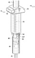
この操作ケーブル40は、図2及び図3に示されるように、その上端部がサポート2Sの筒内に下方側から挿通されることにより、同サポート2Sの筒内に挿通されるステー4Bの内部のプッシュロッド50をプッシュ操作できる状態に組み付けられる。
詳しくは、図3に示されるように、操作ケーブル40は、インナー部材41の上端部に形成されたT字形状の係合突起41P,41Pが、アウター部材42の上端側の周壁に貫通形成された長孔42S,42Sからそれぞれ半径方向の外方に突出した構成となっている。
これにより、インナー部材41は、T字状に突出している係合突起41P,41Pが長孔42S,42S内で移動可能とされる範囲内において、アウター部材42に対して軸方向に相対移動可能とされている。これら係合突起41P,41Pや長孔42S,42Sは、インナー部材41やアウター部材42の軸対称となる周方向の2箇所に形成されている。そして、アウター部材42の上端部には、その管状の端部形状を塞ぐかたちで頭部42Hが形成されている。As shown in FIGS. 2 and 3, the
Specifically, as shown in FIG. 3, the
As a result, the
上記構成の操作ケーブル40は、その上端部をサポート2Sの筒内に下方側から挿通することにより、図12に示されるように、その上端部がサポート2Sに吊り下げられた状態として仮保持されるようになっている。そして、この吊り下げ状態で、ステー4Bをサポート2Sの筒内に上方側から挿通することにより、図13に示されるように、操作ケーブル40をサポート2Sに吊り下げられた状態からステー4Bに吊り下げられた状態へと移行できるようになっている。
そして、このように操作ケーブル40がステー4Bに吊り下げられた状態となることにより、操作ケーブル40は、その下端側が牽引される操作力をステー4B内部のプッシュロッド50に押し操作力として逆転させて伝達できる状態となる。
すなわち、上記した構成を図3を用いて詳しく説明すると、先ず、サポート2Sの周壁には、その下端部から上方に向けて軸方向に延びるスリット状の挿入溝Sd,Sdが貫通して形成されている。これら挿入溝Sd,Sdは、サポート2Sの周方向の2箇所の位置に互いに軸対称となる形状に形成されており、操作ケーブル40のインナー部材41に形成された各係合突起41P,41Pを各溝形状の内部に受け入れてこれらを軸方向に挿通させられるようになっている。The
When the
That is, the above-described configuration will be described in detail with reference to FIG. 3. First, slit-like insertion grooves Sd and Sd extending in the axial direction from the lower end of the
ここで、各挿入溝Sd,Sdは、それらの各係合突起41P,41Pを受け入れていく図示上端側の終端部形状が、図示左右の周方向に向けてそれぞれ滑らかに湾曲した形状に形成されている。具体的には、図3に示されている図示手前側に実線で示されている挿入溝Sdは、その終端部形状が、図示向かって左方向に湾曲した形状となっている。そして、奥側に破線で示されている挿入溝Sdは、その終端部形状が、上記手前側の挿入溝Sdとは軸対称となる図示向かって右方向に湾曲した形状となっている。
これら周方向に湾曲した挿入溝Sd,Sdの各終端部形状は、水平よりも下方に垂れ下がった形状に形成されている。これにより、各挿入溝Sd,Sdの終端位置まで挿通された各係合突起41P,41P(操作ケーブル40)が、その自重によって下方に落下してしまうことがないように、サポート2Sに吊り下げられた状態として安定して保持されるようになっている。Here, each insertion groove Sd, Sd is formed in a shape in which the shape of the end portion on the upper end side in the drawing, which receives the
Each end shape of the insertion grooves Sd and Sd curved in the circumferential direction is formed in a shape that hangs downward from the horizontal. As a result, the
この操作ケーブル40は、インナー部材41の上端部に設けられた各係合突起41P,41Pを各挿入溝Sd,Sdの内部に入れ込んでそのまま上方向(軸方向)に挿通していくことにより、サポート2Sの筒内へと挿通されていく。そして、各係合突起41P,41Pが挿入溝Sd,Sdの軸方向の終端位置まで到達したところで、操作ケーブル40を各終端部の湾曲した形状に合わせて周方向に回し込む操作を行う。これにより、図12に示されるように、各係合突起41P,41Pが各挿入溝Sd,Sdの周方向に湾曲した終端位置に到達し、操作ケーブル40がサポート2Sに吊り下げられた状態となる。
ここで、図3に戻って、アウター部材42の上端部は、合成樹脂によって一体成形されており、サポート2Sの筒内に挿通される軸方向の途中箇所に部分的に半径方向の外方に膨らんだ膨出部42Dが形成されている。この膨出部42Dは、全周がセレーション状に凹凸のついた形状に形成されており、その外径寸法がサポート2Sの筒内の径寸法とほぼ同じ大きさに形成されている。これにより、操作ケーブル40は、その上端部をサポート2Sの筒内に挿通させていく際に、膨出部42Dがサポート2Sの筒内形状に緩やかに嵌合するため、筒内でばたつくことなくスムーズに挿通されるようになっている。The
Here, returning to FIG. 3, the upper end portion of the
そして、図12に示されるように、このサポート2Sの筒内に上方側から挿通されるステー4Bの周壁には、その下端部から上方に向けて軸方向に延びるスリット状の受入溝Bd,Bdが貫通形成されている。これら受入溝Bd,Bdは、ステー4Bの周方向の2箇所の位置に互いに軸対称となる形状に形成されている。これら受入溝Bd,Bdは、ステー4Bをサポート2Sの筒内に上方側から挿し込むことにより、このサポート2Sの筒内に吊り下げられている操作ケーブル40のインナー部材41の各係合突起41P,41Pを各溝形状の内部に受け入れる。そして、各係合突起41P,41Pを受け入れた状態から、ステー4Bを更に挿し込んでいくことにより、各係合突起41P,41Pは、各受入溝Bd,Bdの形状に沿って上方向(軸方向)に挿通されていく。
ここで、各受入溝Bd,Bdは、それらの各係合突起41P,41Pを受け入れていく図示上端側の終端部形状が、前述したサポート2Sに形成された各挿入溝Sd,Sdとは逆の周方向に湾曲した形状に形成されている。これら各受入溝Bd,Bdの周方向に向かう各湾曲形状は、軸方向から水平方向に滑らかに湾曲する形状に形成されている。これにより、各受入溝Bd,Bdは、ステー4Bをサポート2Sの筒内に挿し込んでいく軸方向の押込み操作力によって、サポート2Sの筒内にある各係合突起41P,41Pをその水平方向を向く終端位置までスムーズに受け入れられるようになっている。Then, as shown in FIG. 12, on the peripheral wall of the
Here, each receiving groove Bd, Bd is opposite to each insertion groove Sd, Sd formed in the
したがって、図13に示されるように、各係合突起41P,41Pは、ステー4Bをサポート2Sの筒内に上方側から挿し込むことにより、このステー4Bに形成された各受入溝Bd,Bdの湾曲形状に案内されて周方向に回動操作される。これにより、各係合突起41P,41Pは、前述した各挿入溝Sd,Sdの終端位置に保持された状態からこの状態を脱する方向に引き戻されていく。そして、各係合突起41P,41Pは、各受入溝Bd,Bdの湾曲形状に案内されてそれらの終端位置に到達することにより、各挿入溝Sd,Sdの軸方向に延びる溝形状の位置まで引き戻された状態となる。
これにより、各係合突起41P,41Pは、サポート2Sに吊り下げられてその軸方向移動が規制されていた状態から、ステー4Bに吊り下げられた状態へと移行され、ステー4Bに対する軸方向移動が規制された状態となる。これにより、各係合突起41P,41Pは、サポート2Sに対する軸方向の移動規制状態が解除され、ステー4Bに対して軸方向の移動が規制された状態となる。
このとき、各係合突起41P,41Pは、各挿入溝Sd,Sdの軸方向に延びる形状部位に位置しているために、それらの周方向への移動が規制された状態となっている。これにより、各係合突起41P,41Pが、各挿入溝Sd,Sdの軸方向に延びる溝形状によってガイドされ、各受入溝Bd,Bdの終端位置に保持された状態となっている。これにより、操作ケーブル40のインナー部材41とステー4Bとが互いに軸方向に一体的に連結された状態として、共に一体的となってサポート2Sに対して軸方向に移動可能な状態とされている。Therefore, as shown in FIG. 13, the
As a result, the
At this time, since each
ここで、図14に示されるように、サポート2Sの筒内には、ステー4Bの外周壁に形成された凹状の係止溝Bkと係合可能な板状の係止爪Stが設けられている。この係止爪Stは、常時は附勢によってサポート2Sの筒内に突出した姿勢状態に保持されており、ツマミSbを横から押込む操作を行うことによって筒外へ押し退けられるようになっている。
したがって、ステー4Bをサポート2Sの筒内へと挿し込んでいき、係止溝Bkの挿し込み位置が係止爪Stと合致することにより、係止爪Stはその附勢によって係止溝Bkの内部へと入り込んで係合する。これにより、ステー4Bの挿込方向への移動が規制された状態となってロックされる。このステー4Bの挿込方向への移動を規制した状態は、ツマミSbの押込み操作によって係止爪Stを係止溝Bkから外すことにより解除することができる。なお、係止溝Bkは、ステー4Bに対してその軸方向の複数の箇所に形成されており、上記したツマミSbの押込み操作を適宜行うことによってヘッドレスト4の設置高さ位置を自由に調整できるようになっている。Here, as shown in FIG. 14, in the cylinder of the
Accordingly, the
ところで、前述したステー4Bの挿し込み操作によってステー4Bの下端部とインナー部材41の上端部とが互いに軸連結されることにより、このステー4Bの管内には操作ケーブル40のアウター部材42の頭部42Hが下方側から挿通された状態となる。これにより、ステー4Bの管内に挿通配置されているプッシュロッド50の下端部とアウター部材42の頭部42Hとが、互いに軸方向に近接して配置された状態となる。
なお、厳密には、両者の間には僅かな隙間が形成されており、ステー4Bの挿し込み操作時において、プッシュロッド50が誤ってアウター部材42の頭部42Hにプッシュ操作されないようになっている。
そして、このアウター部材42の頭部42Hとプッシュロッド50の下端部とが軸方向に近接した配置状態では、操作ケーブル40が下端側から牽引操作された操作力を、アウター部材42の頭部42Hによってプッシュロッド50に押し操作力として逆転させて伝達することのできる状態として、両者が互いに軸連結された状態となっている。By the way, the lower end portion of the
Strictly speaking, a slight gap is formed between the two so that the
When the
ところで、前述したヘッドレスト4は、各ステー4B,4Bをサポート2S,2Sの筒内から引き抜く操作によってシートバック2から取り外される。このとき、各ステー4B,4Bを引き抜く操作に伴って、上述したインナー部材41とステー4Bとの軸連結状態が解除されるようになっている。
具体的には、図13を参照して分かるように、ステー4Bをサポート2Sの筒内から上方に引抜いていくと、各係合突起41P,41Pが、サポート2Sの各挿入溝Sd,Sdの湾曲形状に案内されて周方向に回動操作される。これにより、各係合突起41P,41Pが、各受入溝Bd,Bdの終端位置に保持された状態からこの状態を脱する方向に引き戻されていき、各挿入溝Sd,Sdの湾曲形状に案内されてそれらの終端位置に到達するのに伴って、各受入溝Bd,Bdの軸方向に延びる溝形状の位置まで引き戻された状態となる。これにより、図12に示されるように、各係合突起41P,41Pは、ステー4Bに吊り下げられた状態から再びサポート2Sに吊り下げられた状態へと戻される。そして、これにより、前述した操作ケーブル40のアウター部材42の頭部42Hとプッシュロッド50との互いに近接した軸連結状態が解除される。By the way, the
Specifically, as can be seen with reference to FIG. 13, when the
次に、ヘッドレスト移動機構10について説明する。なお、ヘッドレスト移動機構10の構成は図5〜図11にそれぞれ表されているが、図8の状態が各部の構成を最も良く表しているため、この図を用いて各部の構成を説明する。
このヘッドレスト移動機構10は、ヘッドレスト基部4Cに対して支承部4Aを連結するかたちで設けられており、幅方向に一対で設けられた連結リンク12,12と、支持部材13,13と、フック14,14と、係脱部材15と、引張ばね16と、レバー部材17,17と、を有する。
ここで、ヘッドレスト基部4Cは、合成樹脂によって形成されており、板状の後面部11Bと底面部11Dと両側面部11S,11Sと上面部11Uとが一体的に形成された構成となっている。詳しくは、底面部11Dは、後面部11Bの下端縁から前方に延びて形成されている。そして、側面部11S,11Sは、ヘッドレスト基部4Cの幅方向の両サイドにそれぞれ立設されるかたちで形成されている。そして、上面部11Uは、両側面部11S,11Sの上縁同士を繋ぐかたちで形成されている。Next, the
The
Here, the
ここで、図11には、図8のXI線方向から見た図、すなわちヘッドレスト4をその前面側の斜め下方から見た図が表されている。同図に示されるように、ヘッドレスト基部4Cの両側面部11S,11Sの間には、これと平行に、複数の板状のリブ11R・・が立設して形成されており、ヘッドレスト基部4Cが補強されている。
このヘッドレスト基部4Cの底面部11Dには、ステー4B,4Bの上端部分がそれぞれ挿し込まれて一体的に固定されている。これらステー4B,4Bは、管状に形成されており、その上端側の開口部分を底面部11Dの上面側に露出させた格好で固定されている。
また、ヘッドレスト基部4Cの両側面部11S,11Sには、波状の長孔11Hが板厚方向に刳り貫かれて形成されている。これら長孔11H,11Hは、それらの下端部H0,H0と上端部H3,H3との間に、後方側(紙面内右側)に波状に段々に窪んだ形状の第1ストッパ溝H1と第2ストッパ溝H2とがそれぞれに形成されている。Here, FIG. 11 shows a view as seen from the direction of the XI line of FIG. 8, that is, a view of the
The upper end portions of the
In addition, wave-like
次いで、図8に戻って、一対の連結リンク12,12は、合成樹脂によって形成されており、ヘッドレスト基部4Cと支承部4Aとをリンク連結する連結部材として設けられている。これら連結リンク12,12は、幅方向に並べて配設されており、各端部がヘッドレスト基部4Cの上端寄りの部位と支承部4Aの後面側の部位とにそれぞれリンク連結されている。
詳しくは、各連結リンク12,12は、その後方側の端部が、ヘッドレスト基部4Cの両側面部11S,11Sに貫通して設けられた連結軸12Aにそれぞれ回動可能に軸支されている。ここで、各連結リンク12,12は、図11に示されるように、それらの後方側の端部が、両側面部11S,11Sとそれらの内側にあるリブ11R,11Rとの間に挟まれて配置されている。そして、各連結リンク12,12は、両側面部11S,11Sの間に架け渡されている連結軸12Aによってそれぞれ回動可能に軸支されている。
そして、図8に戻って、各連結リンク12,12は、その前方側の端部が、支承部4Aの後面側の部位に幅方向に架け渡された連結軸12Bによって回動可能に軸支されている。これら連結軸12A,12Bは、互いに平行向きに配設されている。
上記の連結リンク12,12は、その後端部を軸支する連結軸12Aを中心に、図示時計回り方向に回動させることにより、ヘッドレスト基部4Cの上面部11Uと当接し、その時計回り方向への回動が規制されるようになっている。Next, returning to FIG. 8, the pair of
Specifically, the end portions on the rear side of each of the connection links 12 and 12 are pivotally supported by
Returning to FIG. 8, each of the connecting
The above-described connecting
次いで、一対の支持部材13,13は、支承部4Aの後面側からその後方側に延びる格好で支承部4Aと一体的に形成されている。これら支持部材13,13は、支承部4Aの幅方向に並べて配設されている。ここで、支承部4Aは、合成樹脂の一体成形により、その前面側が湾曲した曲板形状に形成されている。そして、この支承部4Aには、その後面側に、上述した連結軸12Bを軸支するための部位や支持部材13,13が一体的に形成されている。
これら支持部材13,13は、互いの後端部同士が、幅方向に延びる連結軸13Aによって互いに連結されている。詳しくは、図11に示されるように、各支持部材13,13は、それらの後端部が、それらの両外側に配置されている各リブ11R,11Rとその内側にあるリブ11R,11Rとの間に挟まれて配置されている。そして、これら支持部材13,13の後端部同士を繋ぐ連結軸13Aは、前述した連結軸12Aや連結軸12Bと互いに平行向きに配設されている。
この連結軸13Aは、その各端部がヘッドレスト基部4Cの両側面部11S,11Sに形成された各長孔11H,11H内に挿通された状態で設けられている。これにより、連結軸13Aは、各長孔11H,11Hの孔形状の範囲内でのみ、その前後方向や上下方向に移動可能とされている。なお、両側面部11S,11Sの間に形成されている各リブ11R・・(図11参照)は、長孔11H,11H内を移動する連結軸13Aとは干渉することのない形状に形成されている。Next, the pair of
The
The connecting
次いで、図6に示されるように、一対のフック14,14は、全体がカム形状に形成されており、ヘッドレスト基部4Cの下端寄りの位置で幅方向に並べて配設されている。これらフック14,14は、前述した長孔11H,11H内を移動する連結軸13Aの移動を初期位置に規制するための規制部材として設けられている。
詳しくは、各フック14,14は、図11に示されるように両側面部11S,11Sとそれらの内側にあるリブ11R,11Rとの間に挟まれて配置されており、この間に架け渡された各連結軸14A,14Aによってそれぞれが回動可能に軸支されている。
そして、図6に戻って、これらフック14,14には、その外周縁部の周方向の2箇所に、半径方向の外方に突出する爪形状の上顎部位14Bと下顎部位14Cとが形成されている。これにより、各上顎部位14B,14Bと下顎部位14C,14Cとの間には、半径方向内方に窪んだ凹みが形成されている。この上顎部位14Bと下顎部位14Cとの間の凹みには、前述した連結軸13Aを内部に収められるようになっている。ここで、各連結軸14A,14Aは、前述した各連結軸12A,12Bや連結軸13Aと互いに平行向きに配設されている。Next, as shown in FIG. 6, the pair of
Specifically, as shown in FIG. 11, the
Returning to FIG. 6, these
そして、上述したフック14,14とヘッドレスト基部4Cとの間には、捩りばね14S,14Sがそれぞれ掛着されている。これら捩りばね14S,14Sは、予め捩り込まれた状態で組み付けられており、各フック14,14を図6の位置状態から図示反時計回り方向に回動附勢している。
そして、これらフック14,14の外周縁部には、段差状に窪んだ形状の係止溝14Dがそれぞれ形成されている。これら係止溝14D,14Dには、後述する係脱部材15に設けられた一対の係合腕部15C,15Cがそれぞれ係着されている。これにより、各フック14,14の附勢による反時計回り方向への回動が規制された状態として保持されている。And the torsion springs 14S and 14S are respectively hooked between the
And the locking
したがって、上記構成のフック14,14は、その反時計回り方向への回動が規制された状態では、連結軸13Aを各上顎部位14B,14Bと下顎部位14C,14Cとの間の凹み内に収めた状態として、連結軸13Aを長孔11H,11Hの各下端部H0,H0に係止させた状態に保持している。
ここで、図5に示されるように、連結軸13Aは、連結軸12Aとの間に掛着された引張ばね16によって、常時は連結軸12Aに引き寄せられる方向に附勢されており、長孔11H,11Hの形状に沿って上端部H3,H3に向けて附勢された状態とされている。したがって、連結軸13Aは、常時はこの引張ばね16の附勢に抗して、フック14,14により長孔11H,11Hの各下端部H0,H0に係止された状態(初期位置の状態)として保持されている。
そして、図6に戻って、フック14,14は、係合腕部15C,15Cが図示反時計回り方向に回動操作されてこれらとの係合状態が解除されることにより、捩りばね14S,14Sの附勢力によって図示反時計回り方向に回動する。これにより、フック14,14は、図6の仮想線状態で示されるように、各上顎部位14B,14Bを長孔11H,11Hの孔外に移動させ、下顎部位14C,14Cを下側から押し上げるかたちで長孔11H,11Hの孔内に露出させた姿勢状態となる。これにより、フック14,14による連結軸13Aの係止状態が解除され、図7及び図8に示されるように、連結軸13Aが引張ばね16の附勢力によって長孔11H,11Hの形状に沿って前方かつ上方に附勢移動していく。そして、これにより、支承部4Aが、連結リンク12,12の回動を伴いながらヘッドレスト基部4Cに対して相対的に前方かつ上方に移動していく。Therefore, the
Here, as shown in FIG. 5, the connecting
Returning to FIG. 6, the
ここで、図6に戻って、各フック14,14の図示反時計回り方向への回動を規制する係合腕部15C,15Cは、各フック14,14と係合可能に幅方向に並べて配設されている。詳しくは、各係合腕部15C,15Cは、図11に示されるように各フック14,14と同じ両側面部11S,11Sとそれらの内側にあるリブ11R,11Rとの間に挟まれて配置されている。そして、各係合腕部15C,15Cは、両側面部11S,11Sの間に貫通して設けられた連結軸15Bによって回動可能に軸支されている。この連結軸15Bは、各係合腕部15C,15Cと一体的に連結されており、両側面部11S,11Sに対して回動可能に軸支されている。なお、連結軸15Bは、前述した各連結軸12A,12Bや連結軸13Aと互いに平行向きに配設されている。
そして、この一方の係合腕部15Cとヘッドレスト基部4Cとの間には、捩りばね15Sが掛着されている。この捩りばね15Sは、予め捩り込まれた状態で組み付けられており、図6に示されるように各係合腕部15C,15Cを図示時計回り方向に回動附勢している。これにより、各係合腕部15C,15Cは、常時は各フック14,14の外周面部に押し当てられた状態として、その先端側の部位を各フック14,14の段差状に凹んだ係止溝14D,14Dにそれぞれ係合させた状態として保持されている。これら係合腕部15C,15Cが係止溝14D,14Dに係合した状態では、両者が互いに突き合わされた状態となり、互いの附勢回動が互いによって規制された状態とされている。Here, returning to FIG. 6, the
A
そして、図5に戻って、前述した係合腕部15C,15Cに連結された連結軸15Bの端部には、前述したプッシュロッド50によって回動操作される操作腕部15Aが一体的に連結されている。この操作腕部15Aは、車両後突発生時に、プッシュロッド50が上方に押し操作されることにより、図示反時計回り方向に回動操作される。これにより、操作腕部15Aは、図6に示されるように各係合腕部15C,15Cを同方向に回動操作して、各係合腕部15C,15Cをフック14,14との係合状態から外す。そして、これにより、支承部4Aの初期位置での保持状態が解除されて、支承部4Aが引張ばね16の附勢によって前方かつ上方に移送されていく。
この支承部4Aの前方かつ上方への動きは、図8に示されるように、連結軸13Aが長孔11H,11Hの各上端部H3,H3に到達することで規制されて制止される。そして、この支承部4Aの動きが止まった状態では、支承部4Aは、着座者の頭部から荷重を受けても後方側には押し戻されないようになっている。Returning to FIG. 5, the
As shown in FIG. 8, the forward and upward movement of the
すなわち、連結軸13Aが長孔11H,11Hの各上端部H3,H3に到達すると、支承部4Aに連結された各連結リンク12,12が、ヘッドレスト基部4Cの上面部11Uと当接し、その図示時計回り方向への回動が規制された状態となる。この回動が規制された状態では、支承部4Aが後方側に押し動かされる力が働くと、各連結リンク12,12はヘッドレスト基部4Cの上面部11Uに押し当てられる方向に力の作用を受ける。したがって、支承部4Aは、上記の押圧力を受けても図示反時計回り方向に押し戻されることなく、この衝突対応位置で着座者の頭部を受け止める。
また、支承部4Aは、図7に示されるように、その前方移動の途中過程においても、着座者の頭部に押圧されても後方側には押し戻されないようになっている。すなわち、支承部4Aが前方移動していく途中の段階で、連結軸13Aが後方側に押し戻されるような力が働くと、連結軸13Aは、長孔11H,11Hの後方側(図示右側)に段々に窪んで形成された第1ストッパ溝H1,H1や第2ストッパ溝H2,H2の溝内部に入り込む。これにより、連結軸13Aが後方側に押し戻される動きが規制され、支承部4Aがその前方移動の途中位置状態で保持される。したがって、この衝突対応位置に到達する前の途中位置においても、着座者の頭部を支承部4Aによって受け止めることができる。なお、図7では、連結軸13Aが第2ストッパ溝H2,H2の溝内部に入り込んだ状態が示されている。That is, when the connecting
Further, as shown in FIG. 7, the
ここで、図5に戻って、ヘッドレスト基部4Cには、アーム状の部材によって形成された一対のレバー部材17,17が配設されている。これらレバー部材17,17は、幅方向に並べて配設されており、その後方側の端部がヘッドレスト基部4Cに回動可能に軸支されている。
詳しくは、図11に示されるように、レバー部材17,17は、その後方側の端部が、両外側に配置された各リブ11R,11Rとそれらの内側にあるリブ11R,11Rとの間に挟まれて配置されており、これらの間に架け渡された連結軸17A,17Aによってそれぞれ回動可能に軸支されている。
そして、これらレバー部材17,17とヘッドレスト基部4Cとの間には、捩りばね17S,17Sがそれぞれ掛着されている。これら捩りばね17S,17Sは、図5に示されるように、連結軸17A,17Aに巻回されて設けられており、その一端がレバー部材17,17に掛着され、他端がヘッドレスト基部4Cにそれぞれ掛着されている。これにより、レバー部材17,17は、その自由状態では、各捩りばね17S,17Sのばね力の作用によって、長孔11H,11Hの孔内に露出した姿勢位置に保持されている。Here, returning to FIG. 5, a pair of
Specifically, as shown in FIG. 11, the
And the torsion springs 17S and 17S are respectively hooked between these
このレバー部材17,17の長孔11H,11Hの孔内に露出している図示左側の先端部には、さじ状の受部17Bがそれぞれ形成されている。これら受部17B,17Bは、図7に示されるように、連結軸13Aが長孔11H,11H内を下端部H0,H0から上方に向けて移動していく場合には、これに押し退けられる格好で長孔11H,11Hの孔外へと押し出される。しかし、受部17B,17Bは、図8に示されるように、連結軸13Aが長孔11H,11Hの各上端部H3,H3に到達することにより、捩りばね17S,17Sのばね作用によって再び長孔11H,11Hの孔内に露出した姿勢状態に戻される。
そして、受部17B,17Bは、図9に示されるように、連結軸13Aが長孔11H,11H内を上端部H3,H3から下方に向けて移送される時には、これを先端のさじ形状で受けてキャッチする。そして、この状態から連結軸13Aが更に下方に移送されることにより、各レバー部材17,17は、受部17B,17Bにキャッチされた連結軸13Aに押圧されながら図示反時計回り方向に押し回される。A spoon-shaped receiving
As shown in FIG. 9, when the connecting
これにより、連結軸13Aは、各レバー部材17,17によって移動案内されながら、図10に示されるように下端部H0,H0の近傍まで移送されて受部17B,17Bから外される。このように、連結軸13Aは、長孔11H,11H内を上端部H3,H3から下方に向けて移送されるときには、各レバー部材17,17によって案内されながら、第1ストッパ溝H1,H1や第2ストッパ溝H2,H2に入り込まないように下端部H0,H0までスムーズに移送されるようになっている。
そして、連結軸13Aは、これを長孔11H,11Hの各下端部H0,H0に押し込むように操作することにより、この下端部H0,H0に露出しているフック14,14の各下顎部位14C,14Cを押し下げながら下端部H0,H0へと到達する。これにより、フック14,14は、図6に示されるように、図示時計回り方向に押し回されて、それらの上顎部位14B,14Bを連結軸13Aの上側に回し込んだ姿勢状態となる。
そして、フック14,14は、上記の姿勢状態となったところで各係合腕部15C,15Cと係合し、再び連結軸13Aを初期位置に保持した状態としてロックされる。これにより、支承部4Aが、再び、前方移動する前の初期位置の姿勢に戻された状態として保持される。Thus, the connecting
The connecting
The
次に、本実施例の使用方法について説明する。
すなわち、図1を参照して、車両用シート1は、その車両後突が発生する前の常時は、ヘッドレスト4の支承部4Aが初期位置の姿勢に保持された状態となっている。そして、車両後突が発生することにより、着座者がシートバック2に圧し掛かる背凭れ荷重によって受圧板21が後方側に押動され、この操作力が操作ケーブル40及びプッシュロッド50によって伝達されて係脱部材15が回動操作される。
これにより、支承部4Aの初期位置での保持状態が解除され、支承部4Aは図8に示されるように引張ばね16の附勢力によって図示された衝突対応位置まで移動する。そして、この衝突対応位置に移動した支承部4Aによって、後突時の勢いで後傾してくる着座者の頭部が後方側から受け止められる。Next, the usage method of a present Example is demonstrated.
That is, referring to FIG. 1, the vehicle seat 1 is in a state in which the
As a result, the holding state of the
このように、本実施例のケーブル連結構造によれば、ステー4Bをサポート2Sの筒内に挿し込む動きによって、第1ケーブル(操作ケーブル40のインナー部材41)に設けた係合突起41P,41Pを第2ケーブル(ステー4B)に形成した受入溝Bd,Bdの周方向に曲がった終端位置に係止させられる構成としたことにより、これらの連結端部同士を互いに外れ落ちないように強固に連結することができる。
更に、第2ケーブルとしてのステー4Bをサポート2Sから引抜く操作によって、インナー部材41との軸連結状態を解除できるように構成したことにより、互いに軸方向に強固に連結された両者の軸連結状態をステー4Bを単純に引抜く操作によって簡単に解除することができる。
更に、挿入溝Sd,Sdや受入溝Bd,Bdの周方向に曲がる形状を滑らかに湾曲させて形成したことにより、操作ケーブル40やステー4Bをサポート2Sの筒内に挿通する動きによって、係合突起41P,41Pをこれら溝の周方向に湾曲した終端形状に沿って周方向にスムーズに移動させることができる。
更に、係合突起41P,41Pの係合構造を軸対称構造としたことにより、かかる係合力を、サポート2Sやステー4B等の関係する各部材に対して周方向に均等に作用させることができる。これにより、操作ケーブル40やステー4Bの挿通移動をスムーズに行えるようになると共に、互いの軸連結状態を強固なものとすることができる。
更に、両ケーブルの連結構造を、ステー4Bをサポート2Sの筒内に挿込んで装着する装着部に設定したことにより、ステー4Bをサポート2Sの筒内に挿通したり引抜いたりするヘッドレスト4の脱着操作によって、両ケーブルを簡単に軸連結させることができる。Thus, according to the cable connection structure of the present embodiment, the
In addition, by connecting the
Furthermore, the insertion grooves Sd, Sd and the receiving grooves Bd, Bd are formed by smoothly curving the circumferentially bent shape, so that the
Furthermore, by making the engagement structure of the
Further, the connecting structure of the two cables is set to a mounting portion for inserting and mounting the
続いて、実施例2のケーブル連結構造について、図15を用いて説明する。なお、以下の説明では、実施例1のケーブル連結構造と実質的に同じ構成及び作用を奏する箇所については説明を省略し、異なる箇所について詳しく説明をする。
本実施例では、操作ケーブル40のアウター部材42の上端部に、半径方向の外方に突出した形状の係合突起42P,42Pが軸対称の2箇所に形成されている。この係合突起42P,42Pは、実施例1で示した係合突起41P,41Pのように、サポート2Sに形成された挿入溝Sd,Sdや、ステー4Bに形成された受入溝Bd,Bdの溝形状と係合する構成となっている。すなわち、本実施例では、操作ケーブル40のアウター部材42とステー4Bとが軸連結される構成となっている。Next, the cable connection structure of Example 2 will be described with reference to FIG. In the following description, the description of the portions that exhibit substantially the same configuration and action as the cable connection structure of the first embodiment will be omitted, and different portions will be described in detail.
In the present embodiment,
この操作ケーブル40は、実施例1で示した牽引式のケーブル構造とは異なり、インナー部材41によってステー4Bの管内に挿通されたプッシュロッド50を押し操作するプッシュタイプのケーブル構造となっている。したがって、インナー部材41は、プッシュロッド50に軸方向の押し操作力を伝達可能に比較的剛性の高い棒状部材によって形成されている。そして、このインナー部材41の図示上端部には、プッシュロッド50の押し操作を安定して行えるようにするための台座状の頭部41Hが形成されている。
このように、第1ケーブル40のアウター部材42とステー4Bとを軸連結させる構成としても、ステー4Bをサポート2Sの筒内に挿通したり引抜いたりする操作によって、両者を互いに軸連結させたり解除したりすることができる。The
As described above, even when the
以上、本発明の実施形態を2つの実施例によって説明したが、本発明は上記実施例のほか各種の形態で実施できるものである。
例えば、特開2005−104259号公報等の文献に開示されているように、ヘッドレスト移動機構を両ケーブルがケーブル操作された操作移動量によって、直接、ヘッドレストの支承部がその移動量相当分だけ進行方向に移動操作されるように構成することもできる。
また、第2ケーブルを、ステー自体によって構成したものを示したが、このステーの管内に別途のケーブルを配して構成することもできる。
また、サポートに形成した挿入溝は、その終端部が上方を向いた形状となるように周方向に緩やかに湾曲する形状となっていてもよい。これにより、操作ケーブルを軸方向に真っ直ぐに挿通していく単純な操作によって各係合突起を挿入溝の終端位置までスムーズに挿通させられるようになるため、周方向に回す操作が不要となり操作が簡単となる。しかし、挿入溝の終端部が上向きであるため、仮保持した操作ケーブルが脱落し易くなることには留意が必要である。
また、挿入溝は、サポートの周壁に貫通形成されたものを示したが、サポートの内周壁に凹状に窪みを入れることによっても形成することができる。
また、操作ケーブルのインナー部材に設けられる係合突起やこの係合突起を係合させるための各挿入溝や受入溝は、周方向の1箇所若しくは3箇所以上の位置に形成されていてもよい。また、必ずしも軸対称の配置となっていなくてもよい。
また、本発明のケーブル連結構造を、ヘッドレストのステーをシートバックのサポートの筒内に挿込んで装着する装着部に設定した実施例を示したが、このような連結構造は2つのケーブルを互いに軸方向に連結させるための様々な構成に適用することができる。
Although the embodiment of the present invention has been described with reference to two examples, the present invention can be implemented in various forms in addition to the above-described example.
For example, as disclosed in Japanese Patent Application Laid-Open No. 2005-104259 and the like, the headrest moving mechanism is directly advanced by the amount corresponding to the amount of movement of the headrest moving mechanism according to the amount of movement of the cable operated by both cables. It can also be configured to be moved in the direction.
Further, although the second cable is constituted by the stay itself, the second cable can be constituted by arranging a separate cable in the pipe of the stay.
In addition, the insertion groove formed in the support may have a shape that gently curves in the circumferential direction so that the end portion thereof has a shape facing upward. As a result, each engagement protrusion can be smoothly inserted to the end position of the insertion groove by a simple operation of inserting the operation cable straight in the axial direction. It will be easy. However, since the terminal end of the insertion groove faces upward, it should be noted that the temporarily held operation cable is likely to drop off.
Moreover, although the insertion groove | channel was penetrated and formed in the surrounding wall of a support, it can be formed also by putting a hollow in a concave shape in the inner peripheral wall of a support.
Further, the engagement protrusion provided on the inner member of the operation cable and each insertion groove or receiving groove for engaging the engagement protrusion may be formed at one position in the circumferential direction or at three or more positions. . Moreover, it does not necessarily need to be an axially symmetrical arrangement.
Moreover, although the cable connection structure of the present invention has been shown in an embodiment in which the stay of the headrest is set in the mounting part to be inserted into the cylinder of the seat back support, the connection structure has two cables connected to each other. The present invention can be applied to various configurations for connecting in the axial direction.
Claims (5)
前記両ケーブルの軸方向の連結は、軸方向の移動が規制された筒状の連結部材を介して行われるものであり、
前記第1ケーブルの連結端部にはその半径方向の外方に突出する係合突起が設けられており、前記第2ケーブルの連結端部には該係合突起を軸方向に受け入れ可能な受入溝が軸方向に延びて形成されており、
前記第1ケーブルは、その連結端部を前記連結部材の筒内に軸方向の一方側から挿通することにより前記係合突起が前記連結部材の筒壁に形成された挿入溝の形状に沿って軸方向に受け入れられていくようになっており、
該挿入溝は前記係合突起を受け入れていく軸方向の終端側の形状が周方向の一方に曲がって形成されており、前記係合突起が前記挿入溝の終端位置まで挿通されることにより前記連結部材に対する軸方向の双方向の移動が規制された状態として保持されるようになっており、
前記第2ケーブルの連結端部に形成された受入溝はその係合突起を受け入れていく軸方向の終端側の形状が前記挿入溝の形状とは逆となる周方向の他方に曲がって形成されており、該第2ケーブルの連結端部を前記連結部材の筒内に軸方向の他方側から挿通することにより該筒内に保持された第1ケーブルの係合突起が第2ケーブルの受入溝の形状に沿って軸方向に受け入れられていき、該係合突起が前記受入溝の周方向の他方に曲がった終端位置まで挿通されることにより該係合突起が前記連結部材の挿入溝の終端位置から脱して該連結部材に対する軸方向の移動規制状態が解除されると共に前記第2ケーブルに対する軸方向移動が規制された状態へと移行するようになっており、
前記係合突起が前記第2ケーブルの受入溝の終端位置に到達しその軸方向移動が規制された状態では前記係合突起が前記連結部材に形成された挿入溝の軸方向に延びる溝形状によって前記受入溝の終端位置に保持された状態として両ケーブルが互いに軸方向に一体的に連結されて互いが一体的となって軸方向に移動操作されるようになっていることを特徴とするケーブル連結構造。A cable connection structure for connecting the first cable and the second cable in the axial direction,
The axial connection of the two cables is performed via a cylindrical connecting member in which axial movement is restricted,
The connection end of the first cable is provided with an engagement protrusion protruding outward in the radial direction, and the connection protrusion of the second cable can receive the engagement protrusion in the axial direction. A groove is formed extending in the axial direction,
The first cable is inserted along the shape of the insertion groove formed in the cylindrical wall of the connecting member by inserting the connecting end of the first cable into the connecting member cylinder from one side in the axial direction. It has been accepted in the axial direction,
The insertion groove is formed such that the shape on the end side in the axial direction for receiving the engagement protrusion is bent in one of the circumferential directions, and the engagement protrusion is inserted to the end position of the insertion groove. The two-way movement in the axial direction relative to the connecting member is held in a restricted state,
The receiving groove formed in the connecting end portion of the second cable is formed by bending the other end in the circumferential direction in which the shape on the axial end side for receiving the engaging projection is opposite to the shape of the insertion groove. The engaging protrusion of the first cable held in the cylinder is inserted into the cylinder of the connecting member from the other side in the axial direction by inserting the connecting end of the second cable into the cylinder of the connecting member. The engagement protrusion is inserted to the end position bent in the other circumferential direction of the receiving groove by being received in the axial direction along the shape of the connection member. The axial movement restriction state with respect to the connecting member is released from the position and the axial movement with respect to the second cable is restricted, and the state shifts to the restricted state.
When the engaging protrusion reaches the terminal position of the receiving groove of the second cable and its axial movement is restricted, the engaging protrusion is formed by a groove shape extending in the axial direction of the insertion groove formed in the connecting member. The cable is characterized in that both cables are integrally connected to each other in the axial direction as being held at the terminal position of the receiving groove, and are moved together in the axial direction. Linked structure.
前記第2ケーブルを連結部材の筒内に挿通して両ケーブルが互いに軸方向に一体的に連結された状態で該第2ケーブルを筒内から引抜くことにより、該第2ケーブルの受入溝の終端位置に保持された第1ケーブルの係合突起が前記連結部材の挿入溝の周方向の一方に曲がった終端形状に案内されて該第2ケーブルの受入溝の終端位置から脱して両ケーブルの軸連結状態が解除されるようになっていることを特徴とするケーブル連結構造。The cable connection structure according to claim 1,
By inserting the second cable into the cylinder of the connecting member and pulling out the second cable from the cylinder in a state where both cables are integrally connected to each other in the axial direction, The engagement protrusion of the first cable held at the end position is guided to the end shape bent in one of the circumferential directions of the insertion groove of the connecting member so as to escape from the end position of the receiving groove of the second cable. A cable connection structure characterized in that the shaft connection state is released.
前記連結部材に形成される挿入溝及び前記第2ケーブルに形成される受入溝の少なくとも一方は、その周方向に曲がる形状が滑らかに湾曲して形成されていることを特徴とするケーブル連結構造。The cable connection structure according to claim 1 or 2,
At least one of the insertion groove formed in the connection member and the reception groove formed in the second cable is formed by smoothly curving a shape that bends in the circumferential direction.
前記第1ケーブルに設けられた係合突起は該第1ケーブルの軸対称の複数箇所に設けられており、該係合突起を受け入れる前記連結部材に形成された挿入溝及び前記第2ケーブルに形成された受入溝も該係合突起の配設位置に対応した軸対称の複数箇所に形成されていることを特徴とするケーブル連結構造。The cable connection structure according to any one of claims 1 to 3,
Engagement protrusions provided on the first cable are provided at a plurality of axially symmetrical positions of the first cable, and are formed in the insertion grooves formed in the connecting member that receives the engagement protrusions and in the second cable. A cable connection structure characterized in that the received receiving grooves are also formed at a plurality of axisymmetric positions corresponding to the positions of the engagement protrusions.
前記第1ケーブルは車両用シートのシートバックの内部に配索されており、前記第2ケーブルは該シートバックの上部に取り付けられるヘッドレストの支柱となる管状のステーの管内に配索されており、
前記シートバックの上部には、前記ステーを挿し込むための前記連結部材としての筒状のサポートが設置されており、
前記第1ケーブルは、その連結端部が前記サポートの筒内に下方側から挿通されてその連結端部に設けられた係合突起が該サポートに形成された挿入溝の終端位置に保持されることにより、該サポートの筒内で吊り下げられた状態として保持されるようになっており、
前記ステーをサポートの筒内に上方側から挿し込むことにより、該ステーの管内に挿通された第2ケーブルの受入溝に前記第1ケーブルの係合突起が受け入れられて該受入溝の終端位置に到達し、両ケーブルが軸方向に一体的となって移動できる状態に軸連結されるようになっていることを特徴とするケーブル連結構造。The cable connection structure according to any one of claims 1 to 4,
The first cable is routed inside a seat back of a vehicle seat, and the second cable is routed in a pipe of a tubular stay serving as a headrest column attached to an upper portion of the seat back,
On the upper part of the seat back, a cylindrical support is installed as the connecting member for inserting the stay,
The connection end of the first cable is inserted into the cylinder of the support from the lower side, and the engagement protrusion provided on the connection end is held at the end position of the insertion groove formed in the support. By this, it is held as a suspended state in the cylinder of the support,
By inserting the stay into the cylinder of the support from above, the engagement protrusion of the first cable is received in the receiving groove of the second cable inserted into the pipe of the stay, and the end of the receiving groove is reached. A cable connection structure characterized in that the two cables are axially connected so that they can move integrally in the axial direction.
Priority Applications (1)
| Application Number | Priority Date | Filing Date | Title |
|---|---|---|---|
| JP2008531983A JP4766116B2 (en) | 2006-08-31 | 2007-06-29 | Cable connection structure |
Applications Claiming Priority (4)
| Application Number | Priority Date | Filing Date | Title |
|---|---|---|---|
| JP2006235349 | 2006-08-31 | ||
| JP2006235349 | 2006-08-31 | ||
| JP2008531983A JP4766116B2 (en) | 2006-08-31 | 2007-06-29 | Cable connection structure |
| PCT/JP2007/063112 WO2008026371A1 (en) | 2006-08-31 | 2007-06-29 | Cable connection structure |
Publications (2)
| Publication Number | Publication Date |
|---|---|
| JPWO2008026371A1 JPWO2008026371A1 (en) | 2010-01-14 |
| JP4766116B2 true JP4766116B2 (en) | 2011-09-07 |
Family
ID=39135658
Family Applications (1)
| Application Number | Title | Priority Date | Filing Date |
|---|---|---|---|
| JP2008531983A Expired - Fee Related JP4766116B2 (en) | 2006-08-31 | 2007-06-29 | Cable connection structure |
Country Status (5)
| Country | Link |
|---|---|
| US (1) | US8307734B2 (en) |
| EP (1) | EP2058557B1 (en) |
| JP (1) | JP4766116B2 (en) |
| CN (1) | CN101523079B (en) |
| WO (1) | WO2008026371A1 (en) |
Cited By (1)
| Publication number | Priority date | Publication date | Assignee | Title |
|---|---|---|---|---|
| KR101405118B1 (en) * | 2012-11-16 | 2014-06-10 | 한일이화주식회사 | Active headrest moved by a couple of wire |
Families Citing this family (9)
| Publication number | Priority date | Publication date | Assignee | Title |
|---|---|---|---|---|
| JP5131277B2 (en) * | 2007-09-13 | 2013-01-30 | トヨタ紡織株式会社 | Cable connection structure |
| JP5277953B2 (en) * | 2008-12-25 | 2013-08-28 | トヨタ紡織株式会社 | Cable connection structure |
| JP5509799B2 (en) * | 2009-11-12 | 2014-06-04 | マツダ株式会社 | Vehicle seat system |
| GB2497588B (en) * | 2011-12-16 | 2013-11-13 | Trevor Edouard Lambert | Aircraft seats |
| JP6292003B2 (en) * | 2014-04-25 | 2018-03-14 | トヨタ紡織株式会社 | Vehicle seat |
| KR101971148B1 (en) * | 2017-09-26 | 2019-04-22 | 주식회사 우보테크 | Controlling apparatus of headrest |
| JP6869911B2 (en) * | 2018-02-09 | 2021-05-12 | 株式会社オートネットワーク技術研究所 | Armrest |
| US10569683B2 (en) * | 2018-06-19 | 2020-02-25 | Ford Global Technologies, Llc | Headrest support assembly |
| JP7260489B2 (en) * | 2020-01-08 | 2023-04-18 | トヨタ自動車株式会社 | Operating cable device |
Citations (4)
| Publication number | Priority date | Publication date | Assignee | Title |
|---|---|---|---|---|
| JPS6192620A (en) * | 1984-08-03 | 1986-05-10 | シイクル プジヨ | Adjustable headrest of seat of vehicle |
| JP2001208036A (en) * | 2000-01-28 | 2001-08-03 | Maruyama Mfg Co Ltd | Wire device and throttle wire device |
| JP2005087650A (en) * | 2003-09-19 | 2005-04-07 | Aisin Seiki Co Ltd | Headrest |
| JP2005212596A (en) * | 2004-01-29 | 2005-08-11 | Toyota Boshoku Corp | Vehicle seat |
Family Cites Families (14)
| Publication number | Priority date | Publication date | Assignee | Title |
|---|---|---|---|---|
| JPH0532820U (en) | 1991-10-07 | 1993-04-30 | 中央発條株式会社 | Control cable connection structure |
| AUPN795796A0 (en) * | 1996-02-08 | 1996-02-29 | Henderson's Industries Pty Ltd | Cable connector |
| CN1076131C (en) * | 1996-03-13 | 2001-12-12 | 韩国电气通信公社 | Buffer clamp for erecting cable |
| FR2777325B1 (en) * | 1998-04-09 | 2000-06-02 | Acco La Teledynamique | JOINING DEVICE BETWEEN TWO CABLE SECTIONS, MECHANICAL ASSEMBLY AND MOTOR VEHICLE PROVIDED WITH SAME |
| FR2826699B1 (en) * | 2001-06-29 | 2003-09-05 | Sanitaire Accessoires Services | METHOD FOR MANUFACTURING A SHEATHED CABLE CONTROL DEVICE AND CONTROL DEVICE OBTAINED BY THIS METHOD |
| US6767064B2 (en) * | 2002-02-27 | 2004-07-27 | Lear Corporation | Translatable head restraint for automotive seat backrest |
| JP2003299549A (en) | 2002-04-11 | 2003-10-21 | Auto Network Gijutsu Kenkyusho:Kk | Monitor for rear seat |
| JP4135925B2 (en) | 2003-09-30 | 2008-08-20 | 難波プレス工業株式会社 | seat |
| US8042428B2 (en) * | 2006-08-31 | 2011-10-25 | Toyota Boshoku Kabushiki Kaisha | Cable connection structure |
| US7484798B2 (en) * | 2006-09-13 | 2009-02-03 | Nhk Spring Co., Ltd. | Car seat |
| JP5087975B2 (en) * | 2007-04-06 | 2012-12-05 | トヨタ紡織株式会社 | Vehicle seat |
| JP5087974B2 (en) * | 2007-04-06 | 2012-12-05 | トヨタ紡織株式会社 | Vehicle seat |
| JP5145858B2 (en) * | 2007-10-22 | 2013-02-20 | トヨタ紡織株式会社 | Vehicle seat headrest |
| JP5076830B2 (en) * | 2007-11-21 | 2012-11-21 | トヨタ紡織株式会社 | Clutch mechanism |
-
2007
- 2007-06-29 WO PCT/JP2007/063112 patent/WO2008026371A1/en active Application Filing
- 2007-06-29 EP EP07767899A patent/EP2058557B1/en not_active Expired - Fee Related
- 2007-06-29 US US12/438,870 patent/US8307734B2/en active Active
- 2007-06-29 CN CN2007800373397A patent/CN101523079B/en not_active Expired - Fee Related
- 2007-06-29 JP JP2008531983A patent/JP4766116B2/en not_active Expired - Fee Related
Patent Citations (4)
| Publication number | Priority date | Publication date | Assignee | Title |
|---|---|---|---|---|
| JPS6192620A (en) * | 1984-08-03 | 1986-05-10 | シイクル プジヨ | Adjustable headrest of seat of vehicle |
| JP2001208036A (en) * | 2000-01-28 | 2001-08-03 | Maruyama Mfg Co Ltd | Wire device and throttle wire device |
| JP2005087650A (en) * | 2003-09-19 | 2005-04-07 | Aisin Seiki Co Ltd | Headrest |
| JP2005212596A (en) * | 2004-01-29 | 2005-08-11 | Toyota Boshoku Corp | Vehicle seat |
Cited By (1)
| Publication number | Priority date | Publication date | Assignee | Title |
|---|---|---|---|---|
| KR101405118B1 (en) * | 2012-11-16 | 2014-06-10 | 한일이화주식회사 | Active headrest moved by a couple of wire |
Also Published As
| Publication number | Publication date |
|---|---|
| EP2058557B1 (en) | 2011-05-25 |
| CN101523079A (en) | 2009-09-02 |
| CN101523079B (en) | 2011-02-02 |
| JPWO2008026371A1 (en) | 2010-01-14 |
| US8307734B2 (en) | 2012-11-13 |
| EP2058557A4 (en) | 2010-04-21 |
| US20090317176A1 (en) | 2009-12-24 |
| EP2058557A1 (en) | 2009-05-13 |
| WO2008026371A1 (en) | 2008-03-06 |
Similar Documents
| Publication | Publication Date | Title |
|---|---|---|
| JP4766116B2 (en) | Cable connection structure | |
| JP4877326B2 (en) | Cable connection structure | |
| US8123292B2 (en) | Vehicle seat | |
| US8113576B2 (en) | Cable connecting devices | |
| JP5218405B2 (en) | Cable connection structure | |
| JP5131277B2 (en) | Cable connection structure | |
| JP5087962B2 (en) | Vehicle seat | |
| JP4978172B2 (en) | Vehicle seat | |
| JP4992574B2 (en) | Cable connection structure | |
| JP5082490B2 (en) | Vehicle seat | |
| JP5343547B2 (en) | Clutch mechanism for vehicle seat | |
| JP4779825B2 (en) | Cable connection structure for vehicle seat | |
| JP5029218B2 (en) | Headrest actuator | |
| JP2008056088A (en) | Vehicle seat | |
| JP5071015B2 (en) | Headrest actuator | |
| JP4905159B2 (en) | Wire core member insertion structure | |
| JP4929974B2 (en) | Vehicle seat | |
| JP4821557B2 (en) | Cable connection structure | |
| JP4905158B2 (en) | Wire core member insertion structure | |
| JP2009067247A (en) | Structure of vehicular seat | |
| JP2009214665A (en) | Headrest operation device | |
| JP2009214666A (en) | Headrest operating device | |
| JP2011046366A (en) | Reclining device | |
| JP2009214664A (en) | Headrest operation device |
Legal Events
| Date | Code | Title | Description |
|---|---|---|---|
| TRDD | Decision of grant or rejection written | ||
| A01 | Written decision to grant a patent or to grant a registration (utility model) |
Free format text: JAPANESE INTERMEDIATE CODE: A01 Effective date: 20110517 |
|
| A01 | Written decision to grant a patent or to grant a registration (utility model) |
Free format text: JAPANESE INTERMEDIATE CODE: A01 |
|
| A61 | First payment of annual fees (during grant procedure) |
Free format text: JAPANESE INTERMEDIATE CODE: A61 Effective date: 20110530 |
|
| R150 | Certificate of patent or registration of utility model |
Ref document number: 4766116 Country of ref document: JP Free format text: JAPANESE INTERMEDIATE CODE: R150 Free format text: JAPANESE INTERMEDIATE CODE: R150 |
|
| FPAY | Renewal fee payment (event date is renewal date of database) |
Free format text: PAYMENT UNTIL: 20140624 Year of fee payment: 3 |
|
| FPAY | Renewal fee payment (event date is renewal date of database) |
Free format text: PAYMENT UNTIL: 20140624 Year of fee payment: 3 |
|
| R250 | Receipt of annual fees |
Free format text: JAPANESE INTERMEDIATE CODE: R250 |
|
| R250 | Receipt of annual fees |
Free format text: JAPANESE INTERMEDIATE CODE: R250 |
|
| R250 | Receipt of annual fees |
Free format text: JAPANESE INTERMEDIATE CODE: R250 |
|
| R250 | Receipt of annual fees |
Free format text: JAPANESE INTERMEDIATE CODE: R250 |
|
| R250 | Receipt of annual fees |
Free format text: JAPANESE INTERMEDIATE CODE: R250 |
|
| R250 | Receipt of annual fees |
Free format text: JAPANESE INTERMEDIATE CODE: R250 |
|
| R250 | Receipt of annual fees |
Free format text: JAPANESE INTERMEDIATE CODE: R250 |
|
| LAPS | Cancellation because of no payment of annual fees |