EP3246185A1 - Direct drive system for electric car - Google Patents
Direct drive system for electric car Download PDFInfo
- Publication number
- EP3246185A1 EP3246185A1 EP16170448.1A EP16170448A EP3246185A1 EP 3246185 A1 EP3246185 A1 EP 3246185A1 EP 16170448 A EP16170448 A EP 16170448A EP 3246185 A1 EP3246185 A1 EP 3246185A1
- Authority
- EP
- European Patent Office
- Prior art keywords
- wheels
- control system
- electric car
- direct drive
- driving
- Prior art date
- Legal status (The legal status is an assumption and is not a legal conclusion. Google has not performed a legal analysis and makes no representation as to the accuracy of the status listed.)
- Granted
Links
- 239000000725 suspension Substances 0.000 claims abstract description 8
- 230000001133 acceleration Effects 0.000 claims abstract description 5
- 230000005540 biological transmission Effects 0.000 description 2
- 230000002708 enhancing effect Effects 0.000 description 2
- 230000007423 decrease Effects 0.000 description 1
- 238000010586 diagram Methods 0.000 description 1
- 230000004048 modification Effects 0.000 description 1
- 238000012986 modification Methods 0.000 description 1
Images


Classifications
-
- B—PERFORMING OPERATIONS; TRANSPORTING
- B60—VEHICLES IN GENERAL
- B60K—ARRANGEMENT OR MOUNTING OF PROPULSION UNITS OR OF TRANSMISSIONS IN VEHICLES; ARRANGEMENT OR MOUNTING OF PLURAL DIVERSE PRIME-MOVERS IN VEHICLES; AUXILIARY DRIVES FOR VEHICLES; INSTRUMENTATION OR DASHBOARDS FOR VEHICLES; ARRANGEMENTS IN CONNECTION WITH COOLING, AIR INTAKE, GAS EXHAUST OR FUEL SUPPLY OF PROPULSION UNITS IN VEHICLES
- B60K7/00—Disposition of motor in, or adjacent to, traction wheel
- B60K7/0007—Disposition of motor in, or adjacent to, traction wheel the motor being electric
-
- B—PERFORMING OPERATIONS; TRANSPORTING
- B60—VEHICLES IN GENERAL
- B60G—VEHICLE SUSPENSION ARRANGEMENTS
- B60G3/00—Resilient suspensions for a single wheel
- B60G3/18—Resilient suspensions for a single wheel with two or more pivoted arms, e.g. parallelogram
- B60G3/20—Resilient suspensions for a single wheel with two or more pivoted arms, e.g. parallelogram all arms being rigid
-
- B—PERFORMING OPERATIONS; TRANSPORTING
- B60—VEHICLES IN GENERAL
- B60G—VEHICLE SUSPENSION ARRANGEMENTS
- B60G7/00—Pivoted suspension arms; Accessories thereof
- B60G7/02—Attaching arms to sprung part of vehicle
-
- B—PERFORMING OPERATIONS; TRANSPORTING
- B60—VEHICLES IN GENERAL
- B60G—VEHICLE SUSPENSION ARRANGEMENTS
- B60G2204/00—Indexing codes related to suspensions per se or to auxiliary parts
- B60G2204/10—Mounting of suspension elements
- B60G2204/14—Mounting of suspension arms
- B60G2204/143—Mounting of suspension arms on the vehicle body or chassis
-
- B—PERFORMING OPERATIONS; TRANSPORTING
- B60—VEHICLES IN GENERAL
- B60G—VEHICLE SUSPENSION ARRANGEMENTS
- B60G2204/00—Indexing codes related to suspensions per se or to auxiliary parts
- B60G2204/10—Mounting of suspension elements
- B60G2204/14—Mounting of suspension arms
- B60G2204/147—Mounting of suspension arms on the vehicle engine body
-
- B—PERFORMING OPERATIONS; TRANSPORTING
- B60—VEHICLES IN GENERAL
- B60G—VEHICLE SUSPENSION ARRANGEMENTS
- B60G2204/00—Indexing codes related to suspensions per se or to auxiliary parts
- B60G2204/10—Mounting of suspension elements
- B60G2204/18—Mounting of vehicle engines
-
- B—PERFORMING OPERATIONS; TRANSPORTING
- B60—VEHICLES IN GENERAL
- B60G—VEHICLE SUSPENSION ARRANGEMENTS
- B60G2204/00—Indexing codes related to suspensions per se or to auxiliary parts
- B60G2204/10—Mounting of suspension elements
- B60G2204/18—Mounting of vehicle engines
- B60G2204/182—Electric motor on wheel support
-
- B—PERFORMING OPERATIONS; TRANSPORTING
- B60—VEHICLES IN GENERAL
- B60G—VEHICLE SUSPENSION ARRANGEMENTS
- B60G2300/00—Indexing codes relating to the type of vehicle
- B60G2300/50—Electric vehicles; Hybrid vehicles
-
- B—PERFORMING OPERATIONS; TRANSPORTING
- B60—VEHICLES IN GENERAL
- B60G—VEHICLE SUSPENSION ARRANGEMENTS
- B60G2400/00—Indexing codes relating to detected, measured or calculated conditions or factors
- B60G2400/20—Speed
- B60G2400/208—Speed of wheel rotation
-
- B—PERFORMING OPERATIONS; TRANSPORTING
- B60—VEHICLES IN GENERAL
- B60G—VEHICLE SUSPENSION ARRANGEMENTS
- B60G2400/00—Indexing codes relating to detected, measured or calculated conditions or factors
- B60G2400/30—Propulsion unit conditions
-
- B—PERFORMING OPERATIONS; TRANSPORTING
- B60—VEHICLES IN GENERAL
- B60K—ARRANGEMENT OR MOUNTING OF PROPULSION UNITS OR OF TRANSMISSIONS IN VEHICLES; ARRANGEMENT OR MOUNTING OF PLURAL DIVERSE PRIME-MOVERS IN VEHICLES; AUXILIARY DRIVES FOR VEHICLES; INSTRUMENTATION OR DASHBOARDS FOR VEHICLES; ARRANGEMENTS IN CONNECTION WITH COOLING, AIR INTAKE, GAS EXHAUST OR FUEL SUPPLY OF PROPULSION UNITS IN VEHICLES
- B60K7/00—Disposition of motor in, or adjacent to, traction wheel
- B60K2007/0053—Disposition of motor in, or adjacent to, traction wheel the motor moving relative to the vehicle body and to the wheel axle
-
- B—PERFORMING OPERATIONS; TRANSPORTING
- B60—VEHICLES IN GENERAL
- B60W—CONJOINT CONTROL OF VEHICLE SUB-UNITS OF DIFFERENT TYPE OR DIFFERENT FUNCTION; CONTROL SYSTEMS SPECIALLY ADAPTED FOR HYBRID VEHICLES; ROAD VEHICLE DRIVE CONTROL SYSTEMS FOR PURPOSES NOT RELATED TO THE CONTROL OF A PARTICULAR SUB-UNIT
- B60W2520/00—Input parameters relating to overall vehicle dynamics
- B60W2520/28—Wheel speed
Definitions
- the present invention relates to a direct drive system for an electric car in which a control system controls each of four wheels by using each of four driving motors to reduce power loss and consumption and to enhance driving durability of the electric car.
- a conventional transmission system for an electric car contains a gear box, a differential gear, at least one driving shaft, at least one wheel shaft, and at least one driving motor; wherein each driving motor is configured to drive the gear box, the differential gear, the at least one deriving shaft, and the at least one wheel shaft, but at least one transmission belt further drives the gear box in a friction manner, thus causing great power consumption.
- each driving motor is configured to drive the gear box, the differential gear, the at least one deriving shaft, and the at least one wheel shaft, but at least one transmission belt further drives the gear box in a friction manner, thus causing great power consumption.
- speed change generates between the gear box and the differential gear, the gear box decelerates wheel speed and consumes power seriously.
- the present invention has arisen to mitigate and/or obviate the afore-described disadvantages.
- One aspect of the present invention is to provide a direct drive system for an electric car in which a control system controls each of four wheels by using each of four driving motors to reduce power loss and consumption and to enhance driving durability of the electric car.
- Another aspect of the present invention is to provide a direct drive system for an electric car in which each of the four wheels is driven independently to increase control flexibility, and when one of the four driving motors is broken, the electric car still can be driven to run by others of the four driving motors, thus enhancing driving safety.
- a direct drive system for an electric car contains: a body and four wheels, each of the four wheels including a suspension system, a wheel shaft, and a driving motor mounted on the suspension system.
- an output shaft of the driving motor is rotatably connected with the wheel shaft of each of the four wheels, such that the driving motor independently drives each of the four wheels to rotate.
- the body includes a control system, and the control system has at least one rotation module, an acceleration module, and a brake module.
- the control system is coupled with each of four driving motors to transmit control signals and output signals among the four driving motors and the control system.
- At least one speed sensor for sensing wheel speed.
- a braking sensor for sensing wheel braking.
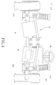
- a direct drive system for an electric car comprising: a body 10 and four wheels 11 to 14; each of the four wheels 11 to 14 includes a suspension system 111, 121, 131 or 141, a wheel shaft 112, 122, 132 or 142, and a driving motor 31, 32, 33 or 34 mounted on the suspension system 111, 121, 131 or 141, wherein an output shaft 311, 321, 331 or 341 of the driving motor 31, 32, 33, 34 is rotatably connected with the wheel shaft 112, 122, 132 or 142 of each of the four wheels 11 to 14 (as shown in FIG.4 ), such that the driving motor 31, 32, 33 or 34 independently drives each of the four wheels 11 to 14 to rotate, thus balancing a height difference during driving.
- the body 10 includes a control system 20, and the control system 20 has at least one rotation module 21, an acceleration module 22, and a brake module 23, wherein between the control system 20 and each of the four wheels 11 to 14 are defined at least one speed sensor 251 for sensing wheel speed and a braking sensor 252 for sensing wheel braking, and the control system 20 is coupled with each of four driving motors 31 to 34 to transmit control signals and output signals among the four driving motors 31 to 34 and the control system 20.
- the direct drive system of the present invention decreases power consumption of the electric car and drives the electric car to run durably.
- the control system 20 starts the electric car, stops the electric car, and controls turning direction, acceleration, deceleration, and braking of the electric car, wherein control codes of starting, stopping, turning, accelerating, decelerating, and braking the electric car are encode to the control signals which are transmitted to drive each of the four driving motors 31 to 34 and are sent back to the control system 20 after the at least one speed sensor 251 senses the wheel speed and the braking sensor 252 senses the wheel braking.
- control system 20 controls each of the four wheels 11 to 14 by using each of the four driving motors 31 to 34 to reduce power loss and consumption and to enhance driving durability of the electric car.
- each of the four wheels 11 to 14 is driven independently to increase control flexibility, and when one of the four driving motors 31 to 34 is broken, the electric car still can be driven to run by others of the four driving motors 31 to 34, thus enhancing driving safety.
Landscapes
- Engineering & Computer Science (AREA)
- Mechanical Engineering (AREA)
- Chemical & Material Sciences (AREA)
- Combustion & Propulsion (AREA)
- Transportation (AREA)
- Electric Propulsion And Braking For Vehicles (AREA)
- Arrangement Or Mounting Of Propulsion Units For Vehicles (AREA)
Abstract
Description
- The present invention relates to a direct drive system for an electric car in which a control system controls each of four wheels by using each of four driving motors to reduce power loss and consumption and to enhance driving durability of the electric car.
- A conventional transmission system for an electric car contains a gear box, a differential gear, at least one driving shaft, at least one wheel shaft, and at least one driving motor; wherein each driving motor is configured to drive the gear box, the differential gear, the at least one deriving shaft, and the at least one wheel shaft, but at least one transmission belt further drives the gear box in a friction manner, thus causing great power consumption. In addition, although speed change generates between the gear box and the differential gear, the gear box decelerates wheel speed and consumes power seriously.
- The present invention has arisen to mitigate and/or obviate the afore-described disadvantages.
- One aspect of the present invention is to provide a direct drive system for an electric car in which a control system controls each of four wheels by using each of four driving motors to reduce power loss and consumption and to enhance driving durability of the electric car.
- Another aspect of the present invention is to provide a direct drive system for an electric car in which each of the four wheels is driven independently to increase control flexibility, and when one of the four driving motors is broken, the electric car still can be driven to run by others of the four driving motors, thus enhancing driving safety.
- To obtain the above, a direct drive system for an electric car provided by the present invention contains: a body and four wheels, each of the four wheels including a suspension system, a wheel shaft, and a driving motor mounted on the suspension system.
- Preferably, an output shaft of the driving motor is rotatably connected with the wheel shaft of each of the four wheels, such that the driving motor independently drives each of the four wheels to rotate.
- Preferably, the body includes a control system, and the control system has at least one rotation module, an acceleration module, and a brake module. The control system is coupled with each of four driving motors to transmit control signals and output signals among the four driving motors and the control system.
- Preferably, between the control system and each of the four wheels is defined at least one speed sensor for sensing wheel speed.
- Preferably, between the control system and each of the four wheels is defined a braking sensor for sensing wheel braking.
-
-
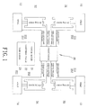
FIG. 1 is a structural diagram showing the assembly of a direct drive system for an electric car according to a preferred embodiment of the present invention. -
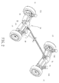
FIG. 2 is a perspective view showing the assembly of the direct drive system for the electric car according to the preferred embodiment of the present invention. -
FIG. 3 is a plan view showing the assembly of the direct drive system for the electric car according to the preferred embodiment of the present invention. -
FIG 4 is another plan view showing the assembly of the direct drive system for the electric car according to the preferred embodiment of the present invention -
FIG. 5 is also another plan view showing the assembly of the direct drive system for the electric car according to the preferred embodiment of the present invention - With reference to
FIGS. 1 to 5 , a direct drive system for an electric car according to a preferred embodiment of the present invention, wherein the electric car comprises: abody 10 and fourwheels 11 to 14; each of the fourwheels 11 to 14 includes asuspension system wheel shaft driving motor suspension system driving motor wheel shaft wheels 11 to 14 (as shown inFIG.4 ), such that thedriving motor wheels 11 to 14 to rotate, thus balancing a height difference during driving. - The
body 10 includes acontrol system 20, and thecontrol system 20 has at least onerotation module 21, anacceleration module 22, and abrake module 23, wherein between thecontrol system 20 and each of the fourwheels 11 to 14 are defined at least onespeed sensor 251 for sensing wheel speed and abraking sensor 252 for sensing wheel braking, and thecontrol system 20 is coupled with each of fourdriving motors 31 to 34 to transmit control signals and output signals among the fourdriving motors 31 to 34 and thecontrol system 20. - Thereby, the direct drive system of the present invention decreases power consumption of the electric car and drives the electric car to run durably.
- In operation, as illustrated in
FIGS. 1 to 3 , thecontrol system 20 starts the electric car, stops the electric car, and controls turning direction, acceleration, deceleration, and braking of the electric car, wherein control codes of starting, stopping, turning, accelerating, decelerating, and braking the electric car are encode to the control signals which are transmitted to drive each of the fourdriving motors 31 to 34 and are sent back to thecontrol system 20 after the at least onespeed sensor 251 senses the wheel speed and thebraking sensor 252 senses the wheel braking. - Thereby, the
control system 20 controls each of the fourwheels 11 to 14 by using each of the fourdriving motors 31 to 34 to reduce power loss and consumption and to enhance driving durability of the electric car. Preferably, each of the fourwheels 11 to 14 is driven independently to increase control flexibility, and when one of the fourdriving motors 31 to 34 is broken, the electric car still can be driven to run by others of the fourdriving motors 31 to 34, thus enhancing driving safety. - While the preferred embodiments of the invention have been set forth for the purpose of disclosure, modifications of the disclosed embodiments of the invention as well as other embodiments thereof may occur to those skilled in the art. The scope of the claims should not be limited by the preferred embodiments set forth in the examples, but should be given the broadest interpretation consistent with the description as a whole.
Claims (3)
- A direct drive system for an electric car comprising: a body (10) and four wheels (11, 12, 13, 14), each of the four wheels (11, 12, 13, 14) including a suspension system (111, 121, 131, 141), a wheel shaft (112, 122, 132, 142), and a driving motor (31, 32, 33, 34) mounted on the suspension system (111, 121, 131, 141); characterized in that
an output shaft (311, 321, 331, 341) of the driving motor (31, 32, 33, 34) is rotatably connected with the wheel shaft (112, 122, 132, 142) of each of the four wheels (11, 12, 13, 14), such that the driving motor (31, 32, 33, 34) independently drives each of the four wheels (11, 12, 13, 14) to rotate;
the body (10) includes a control system (20), and the control system (20) has at least one rotation module (21), an acceleration module (22), and a brake module (23); and
the control system (20) is coupled with each of four driving motors (31, 32, 33, 34) to transmit control signals and output signals among the four driving motors (31, 32, 33, 34) and the control system (20). - The direct drive system for the electric car as claimed in claim 1, characterized in that between the control system (20) and each of the four wheels (11, 12, 13, 14) is defined at least one speed sensor (251) for sensing wheel speed.
- The direct drive system for the electric car as claimed in claim 1 or 2, characterized in that between the control system (20) and each of the four wheels (11, 12, 13, 14) is defined a braking sensor (252) for sensing wheel braking.
Priority Applications (2)
| Application Number | Priority Date | Filing Date | Title |
|---|---|---|---|
| ES16170448T ES2831370T3 (en) | 2016-05-19 | 2016-05-19 | Direct drive system for an electric car |
| EP16170448.1A EP3246185B1 (en) | 2016-05-19 | 2016-05-19 | Direct drive system for electric car |
Applications Claiming Priority (1)
| Application Number | Priority Date | Filing Date | Title |
|---|---|---|---|
| EP16170448.1A EP3246185B1 (en) | 2016-05-19 | 2016-05-19 | Direct drive system for electric car |
Publications (2)
| Publication Number | Publication Date |
|---|---|
| EP3246185A1 true EP3246185A1 (en) | 2017-11-22 |
| EP3246185B1 EP3246185B1 (en) | 2020-09-16 |
Family
ID=56068720
Family Applications (1)
| Application Number | Title | Priority Date | Filing Date |
|---|---|---|---|
| EP16170448.1A Active EP3246185B1 (en) | 2016-05-19 | 2016-05-19 | Direct drive system for electric car |
Country Status (2)
| Country | Link |
|---|---|
| EP (1) | EP3246185B1 (en) |
| ES (1) | ES2831370T3 (en) |
Cited By (2)
| Publication number | Priority date | Publication date | Assignee | Title |
|---|---|---|---|---|
| CN108340767A (en) * | 2018-01-24 | 2018-07-31 | 简式国际汽车设计(北京)有限公司 | A kind of carrying plate spring suspension brackets dual wheel rims motor bridge and new-energy automobile |
| CN108382190A (en) * | 2018-02-10 | 2018-08-10 | 山东国金汽车制造有限公司 | A kind of New-type motor vehicle electrical machinery arrangement and its mode of braking |
Citations (3)
| Publication number | Priority date | Publication date | Assignee | Title |
|---|---|---|---|---|
| US20090236157A1 (en) * | 2006-09-19 | 2009-09-24 | Yoshinobu Akamatsu | Sensor-equipped axle unit having a built-in motor of in-wheel type |
| DE102010049615A1 (en) * | 2009-11-25 | 2011-05-26 | Schaeffler Technologies Gmbh & Co. Kg | Wheel drive device for driving wheel of vehicle, has swivel bearing assigned to electrical drive machine for direct mounting of drive machine at chassis of vehicle and including length compensation device within device |
| DE102013213656A1 (en) * | 2012-07-26 | 2014-01-30 | Schaeffler Technologies AG & Co. KG | Axle structure for motor car, has drive unit that is provided for driving wheel and is supported on plate spring fastened at fixed point of motor car |
-
2016
- 2016-05-19 ES ES16170448T patent/ES2831370T3/en active Active
- 2016-05-19 EP EP16170448.1A patent/EP3246185B1/en active Active
Patent Citations (3)
| Publication number | Priority date | Publication date | Assignee | Title |
|---|---|---|---|---|
| US20090236157A1 (en) * | 2006-09-19 | 2009-09-24 | Yoshinobu Akamatsu | Sensor-equipped axle unit having a built-in motor of in-wheel type |
| DE102010049615A1 (en) * | 2009-11-25 | 2011-05-26 | Schaeffler Technologies Gmbh & Co. Kg | Wheel drive device for driving wheel of vehicle, has swivel bearing assigned to electrical drive machine for direct mounting of drive machine at chassis of vehicle and including length compensation device within device |
| DE102013213656A1 (en) * | 2012-07-26 | 2014-01-30 | Schaeffler Technologies AG & Co. KG | Axle structure for motor car, has drive unit that is provided for driving wheel and is supported on plate spring fastened at fixed point of motor car |
Cited By (2)
| Publication number | Priority date | Publication date | Assignee | Title |
|---|---|---|---|---|
| CN108340767A (en) * | 2018-01-24 | 2018-07-31 | 简式国际汽车设计(北京)有限公司 | A kind of carrying plate spring suspension brackets dual wheel rims motor bridge and new-energy automobile |
| CN108382190A (en) * | 2018-02-10 | 2018-08-10 | 山东国金汽车制造有限公司 | A kind of New-type motor vehicle electrical machinery arrangement and its mode of braking |
Also Published As
| Publication number | Publication date |
|---|---|
| ES2831370T3 (en) | 2021-06-08 |
| EP3246185B1 (en) | 2020-09-16 |
Similar Documents
| Publication | Publication Date | Title |
|---|---|---|
| JP6714333B2 (en) | Vehicle drive system and control method thereof | |
| US8649950B2 (en) | Driving system having epicycle gear sets with dual output ends equipped with individually-controlled multiple speed-ratio device | |
| CN103373342B (en) | Distinguish the system and method for the moment of torsion between wheel | |
| EP2371601B1 (en) | Individual-powered dual CVT differential system with stabilizing device | |
| EP3246185A1 (en) | Direct drive system for electric car | |
| CN101953739B (en) | Bidirectional speed-restriction anti-lock device of wheelchair | |
| CA3100532C (en) | System and method for two step motor for electric vehicle (ev) truck and commercial vehicle applications | |
| CN102072270B (en) | Electric brake | |
| CN205715477U (en) | A kind of drive mechanism of gear box in electric tricycle | |
| ES2013956A6 (en) | Elevator machine | |
| EP2634032B1 (en) | Differential drive system having individual clutch control and mutual flexibility transmission | |
| CN115664108A (en) | Middle motor for electric power-assisted bicycle | |
| EP1721855A3 (en) | Controller for elevator | |
| CN201679890U (en) | Novel electronic mechanical brake for vehicle | |
| CN114598098A (en) | Two-in-one permanent magnet synchronous traction machine special for elevator | |
| CN206344169U (en) | Robot steering wheel | |
| ES470726A1 (en) | Drive system for vehicles, especially for lift trucks. | |
| CN206067539U (en) | A kind of pure electric automobile power assembly | |
| CN219172181U (en) | Transmission system for vehicle and vehicle | |
| KR101682249B1 (en) | In Wheel Driven System | |
| CN203537146U (en) | Motor combination driving device | |
| CN107599873A (en) | The drive device of double wheel hub motor powered automobile | |
| KR20120090316A (en) | In wheel type power transmitting device for vehicle | |
| CN205855393U (en) | Piler with even deceleration synchronization brake unit | |
| CN205114917U (en) | Car capstan winch |
Legal Events
| Date | Code | Title | Description |
|---|---|---|---|
| PUAI | Public reference made under article 153(3) epc to a published international application that has entered the european phase |
Free format text: ORIGINAL CODE: 0009012 |
|
| STAA | Information on the status of an ep patent application or granted ep patent |
Free format text: STATUS: THE APPLICATION HAS BEEN PUBLISHED |
|
| AK | Designated contracting states |
Kind code of ref document: A1 Designated state(s): AL AT BE BG CH CY CZ DE DK EE ES FI FR GB GR HR HU IE IS IT LI LT LU LV MC MK MT NL NO PL PT RO RS SE SI SK SM TR |
|
| AX | Request for extension of the european patent |
Extension state: BA ME |
|
| STAA | Information on the status of an ep patent application or granted ep patent |
Free format text: STATUS: REQUEST FOR EXAMINATION WAS MADE |
|
| 17P | Request for examination filed |
Effective date: 20180522 |
|
| RBV | Designated contracting states (corrected) |
Designated state(s): AL AT BE BG CH CY CZ DE DK EE ES FI FR GB GR HR HU IE IS IT LI LT LU LV MC MK MT NL NO PL PT RO RS SE SI SK SM TR |
|
| GRAP | Despatch of communication of intention to grant a patent |
Free format text: ORIGINAL CODE: EPIDOSNIGR1 |
|
| STAA | Information on the status of an ep patent application or granted ep patent |
Free format text: STATUS: GRANT OF PATENT IS INTENDED |
|
| INTG | Intention to grant announced |
Effective date: 20200331 |
|
| GRAS | Grant fee paid |
Free format text: ORIGINAL CODE: EPIDOSNIGR3 |
|
| GRAA | (expected) grant |
Free format text: ORIGINAL CODE: 0009210 |
|
| STAA | Information on the status of an ep patent application or granted ep patent |
Free format text: STATUS: THE PATENT HAS BEEN GRANTED |
|
| AK | Designated contracting states |
Kind code of ref document: B1 Designated state(s): AL AT BE BG CH CY CZ DE DK EE ES FI FR GB GR HR HU IE IS IT LI LT LU LV MC MK MT NL NO PL PT RO RS SE SI SK SM TR |
|
| REG | Reference to a national code |
Ref country code: GB Ref legal event code: FG4D |
|
| REG | Reference to a national code |
Ref country code: CH Ref legal event code: EP |
|
| REG | Reference to a national code |
Ref country code: DE Ref legal event code: R096 Ref document number: 602016043992 Country of ref document: DE |
|
| REG | Reference to a national code |
Ref country code: IE Ref legal event code: FG4D |
|
| REG | Reference to a national code |
Ref country code: AT Ref legal event code: REF Ref document number: 1313844 Country of ref document: AT Kind code of ref document: T Effective date: 20201015 |
|
| PG25 | Lapsed in a contracting state [announced via postgrant information from national office to epo] |
Ref country code: NO Free format text: LAPSE BECAUSE OF FAILURE TO SUBMIT A TRANSLATION OF THE DESCRIPTION OR TO PAY THE FEE WITHIN THE PRESCRIBED TIME-LIMIT Effective date: 20201216 Ref country code: HR Free format text: LAPSE BECAUSE OF FAILURE TO SUBMIT A TRANSLATION OF THE DESCRIPTION OR TO PAY THE FEE WITHIN THE PRESCRIBED TIME-LIMIT Effective date: 20200916 Ref country code: SE Free format text: LAPSE BECAUSE OF FAILURE TO SUBMIT A TRANSLATION OF THE DESCRIPTION OR TO PAY THE FEE WITHIN THE PRESCRIBED TIME-LIMIT Effective date: 20200916 Ref country code: BG Free format text: LAPSE BECAUSE OF FAILURE TO SUBMIT A TRANSLATION OF THE DESCRIPTION OR TO PAY THE FEE WITHIN THE PRESCRIBED TIME-LIMIT Effective date: 20201216 Ref country code: FI Free format text: LAPSE BECAUSE OF FAILURE TO SUBMIT A TRANSLATION OF THE DESCRIPTION OR TO PAY THE FEE WITHIN THE PRESCRIBED TIME-LIMIT Effective date: 20200916 |
|
| REG | Reference to a national code |
Ref country code: AT Ref legal event code: MK05 Ref document number: 1313844 Country of ref document: AT Kind code of ref document: T Effective date: 20200916 |
|
| REG | Reference to a national code |
Ref country code: NL Ref legal event code: MP Effective date: 20200916 |
|
| PG25 | Lapsed in a contracting state [announced via postgrant information from national office to epo] |
Ref country code: LV Free format text: LAPSE BECAUSE OF FAILURE TO SUBMIT A TRANSLATION OF THE DESCRIPTION OR TO PAY THE FEE WITHIN THE PRESCRIBED TIME-LIMIT Effective date: 20200916 Ref country code: RS Free format text: LAPSE BECAUSE OF FAILURE TO SUBMIT A TRANSLATION OF THE DESCRIPTION OR TO PAY THE FEE WITHIN THE PRESCRIBED TIME-LIMIT Effective date: 20200916 |
|
| REG | Reference to a national code |
Ref country code: LT Ref legal event code: MG4D |
|
| PG25 | Lapsed in a contracting state [announced via postgrant information from national office to epo] |
Ref country code: EE Free format text: LAPSE BECAUSE OF FAILURE TO SUBMIT A TRANSLATION OF THE DESCRIPTION OR TO PAY THE FEE WITHIN THE PRESCRIBED TIME-LIMIT Effective date: 20200916 Ref country code: LT Free format text: LAPSE BECAUSE OF FAILURE TO SUBMIT A TRANSLATION OF THE DESCRIPTION OR TO PAY THE FEE WITHIN THE PRESCRIBED TIME-LIMIT Effective date: 20200916 Ref country code: PT Free format text: LAPSE BECAUSE OF FAILURE TO SUBMIT A TRANSLATION OF THE DESCRIPTION OR TO PAY THE FEE WITHIN THE PRESCRIBED TIME-LIMIT Effective date: 20210118 Ref country code: SM Free format text: LAPSE BECAUSE OF FAILURE TO SUBMIT A TRANSLATION OF THE DESCRIPTION OR TO PAY THE FEE WITHIN THE PRESCRIBED TIME-LIMIT Effective date: 20200916 Ref country code: RO Free format text: LAPSE BECAUSE OF FAILURE TO SUBMIT A TRANSLATION OF THE DESCRIPTION OR TO PAY THE FEE WITHIN THE PRESCRIBED TIME-LIMIT Effective date: 20200916 Ref country code: CZ Free format text: LAPSE BECAUSE OF FAILURE TO SUBMIT A TRANSLATION OF THE DESCRIPTION OR TO PAY THE FEE WITHIN THE PRESCRIBED TIME-LIMIT Effective date: 20200916 |
|
| PG25 | Lapsed in a contracting state [announced via postgrant information from national office to epo] |
Ref country code: AL Free format text: LAPSE BECAUSE OF FAILURE TO SUBMIT A TRANSLATION OF THE DESCRIPTION OR TO PAY THE FEE WITHIN THE PRESCRIBED TIME-LIMIT Effective date: 20200916 Ref country code: AT Free format text: LAPSE BECAUSE OF FAILURE TO SUBMIT A TRANSLATION OF THE DESCRIPTION OR TO PAY THE FEE WITHIN THE PRESCRIBED TIME-LIMIT Effective date: 20200916 Ref country code: PL Free format text: LAPSE BECAUSE OF FAILURE TO SUBMIT A TRANSLATION OF THE DESCRIPTION OR TO PAY THE FEE WITHIN THE PRESCRIBED TIME-LIMIT Effective date: 20200916 Ref country code: IS Free format text: LAPSE BECAUSE OF FAILURE TO SUBMIT A TRANSLATION OF THE DESCRIPTION OR TO PAY THE FEE WITHIN THE PRESCRIBED TIME-LIMIT Effective date: 20210116 |
|
| REG | Reference to a national code |
Ref country code: ES Ref legal event code: FG2A Ref document number: 2831370 Country of ref document: ES Kind code of ref document: T3 Effective date: 20210608 |
|
| REG | Reference to a national code |
Ref country code: DE Ref legal event code: R097 Ref document number: 602016043992 Country of ref document: DE |
|
| PG25 | Lapsed in a contracting state [announced via postgrant information from national office to epo] |
Ref country code: SK Free format text: LAPSE BECAUSE OF FAILURE TO SUBMIT A TRANSLATION OF THE DESCRIPTION OR TO PAY THE FEE WITHIN THE PRESCRIBED TIME-LIMIT Effective date: 20200916 |
|
| PLBE | No opposition filed within time limit |
Free format text: ORIGINAL CODE: 0009261 |
|
| STAA | Information on the status of an ep patent application or granted ep patent |
Free format text: STATUS: NO OPPOSITION FILED WITHIN TIME LIMIT |
|
| 26N | No opposition filed |
Effective date: 20210617 |
|
| PG25 | Lapsed in a contracting state [announced via postgrant information from national office to epo] |
Ref country code: SI Free format text: LAPSE BECAUSE OF FAILURE TO SUBMIT A TRANSLATION OF THE DESCRIPTION OR TO PAY THE FEE WITHIN THE PRESCRIBED TIME-LIMIT Effective date: 20200916 Ref country code: DK Free format text: LAPSE BECAUSE OF FAILURE TO SUBMIT A TRANSLATION OF THE DESCRIPTION OR TO PAY THE FEE WITHIN THE PRESCRIBED TIME-LIMIT Effective date: 20200916 |
|
| PG25 | Lapsed in a contracting state [announced via postgrant information from national office to epo] |
Ref country code: MC Free format text: LAPSE BECAUSE OF FAILURE TO SUBMIT A TRANSLATION OF THE DESCRIPTION OR TO PAY THE FEE WITHIN THE PRESCRIBED TIME-LIMIT Effective date: 20200916 Ref country code: LU Free format text: LAPSE BECAUSE OF NON-PAYMENT OF DUE FEES Effective date: 20210519 |
|
| REG | Reference to a national code |
Ref country code: BE Ref legal event code: MM Effective date: 20210531 |
|
| PG25 | Lapsed in a contracting state [announced via postgrant information from national office to epo] |
Ref country code: IE Free format text: LAPSE BECAUSE OF NON-PAYMENT OF DUE FEES Effective date: 20210519 |
|
| PG25 | Lapsed in a contracting state [announced via postgrant information from national office to epo] |
Ref country code: BE Free format text: LAPSE BECAUSE OF NON-PAYMENT OF DUE FEES Effective date: 20210531 |
|
| PGFP | Annual fee paid to national office [announced via postgrant information from national office to epo] |
Ref country code: IT Payment date: 20220531 Year of fee payment: 7 Ref country code: GB Payment date: 20220511 Year of fee payment: 7 Ref country code: FR Payment date: 20220511 Year of fee payment: 7 Ref country code: ES Payment date: 20220617 Year of fee payment: 7 Ref country code: DE Payment date: 20220510 Year of fee payment: 7 |
|
| PGFP | Annual fee paid to national office [announced via postgrant information from national office to epo] |
Ref country code: CH Payment date: 20220526 Year of fee payment: 7 |
|
| PG25 | Lapsed in a contracting state [announced via postgrant information from national office to epo] |
Ref country code: HU Free format text: LAPSE BECAUSE OF FAILURE TO SUBMIT A TRANSLATION OF THE DESCRIPTION OR TO PAY THE FEE WITHIN THE PRESCRIBED TIME-LIMIT; INVALID AB INITIO Effective date: 20160519 |
|
| PG25 | Lapsed in a contracting state [announced via postgrant information from national office to epo] |
Ref country code: NL Free format text: LAPSE BECAUSE OF NON-PAYMENT OF DUE FEES Effective date: 20200923 Ref country code: CY Free format text: LAPSE BECAUSE OF FAILURE TO SUBMIT A TRANSLATION OF THE DESCRIPTION OR TO PAY THE FEE WITHIN THE PRESCRIBED TIME-LIMIT Effective date: 20200916 |
|
| PG25 | Lapsed in a contracting state [announced via postgrant information from national office to epo] |
Ref country code: GR Free format text: LAPSE BECAUSE OF FAILURE TO SUBMIT A TRANSLATION OF THE DESCRIPTION OR TO PAY THE FEE WITHIN THE PRESCRIBED TIME-LIMIT Effective date: 20200916 |
|
| REG | Reference to a national code |
Ref country code: DE Ref legal event code: R119 Ref document number: 602016043992 Country of ref document: DE |
|
| REG | Reference to a national code |
Ref country code: CH Ref legal event code: PL |
|
| GBPC | Gb: european patent ceased through non-payment of renewal fee |
Effective date: 20230519 |
|
| PG25 | Lapsed in a contracting state [announced via postgrant information from national office to epo] |
Ref country code: LI Free format text: LAPSE BECAUSE OF NON-PAYMENT OF DUE FEES Effective date: 20230531 Ref country code: CH Free format text: LAPSE BECAUSE OF NON-PAYMENT OF DUE FEES Effective date: 20230531 |
|
| PG25 | Lapsed in a contracting state [announced via postgrant information from national office to epo] |
Ref country code: MK Free format text: LAPSE BECAUSE OF FAILURE TO SUBMIT A TRANSLATION OF THE DESCRIPTION OR TO PAY THE FEE WITHIN THE PRESCRIBED TIME-LIMIT Effective date: 20200916 Ref country code: IT Free format text: LAPSE BECAUSE OF NON-PAYMENT OF DUE FEES Effective date: 20230519 Ref country code: DE Free format text: LAPSE BECAUSE OF NON-PAYMENT OF DUE FEES Effective date: 20231201 Ref country code: GB Free format text: LAPSE BECAUSE OF NON-PAYMENT OF DUE FEES Effective date: 20230519 |