EP3246180A1 - Non-pneumatic tire - Google Patents
Non-pneumatic tire Download PDFInfo
- Publication number
- EP3246180A1 EP3246180A1 EP16737238.2A EP16737238A EP3246180A1 EP 3246180 A1 EP3246180 A1 EP 3246180A1 EP 16737238 A EP16737238 A EP 16737238A EP 3246180 A1 EP3246180 A1 EP 3246180A1
- Authority
- EP
- European Patent Office
- Prior art keywords
- rubber portion
- tire
- ring
- base rubber
- shaped body
- Prior art date
- Legal status (The legal status is an assumption and is not a legal conclusion. Google has not performed a legal analysis and makes no representation as to the accuracy of the status listed.)
- Granted
Links
- 229920001971 elastomer Polymers 0.000 claims abstract description 128
- 239000005060 rubber Substances 0.000 claims abstract description 127
- 230000002093 peripheral effect Effects 0.000 claims abstract description 85
- 238000001746 injection moulding Methods 0.000 claims abstract description 7
- 239000012778 molding material Substances 0.000 claims abstract description 7
- 239000000463 material Substances 0.000 description 11
- 239000000203 mixture Substances 0.000 description 3
- 238000000465 moulding Methods 0.000 description 3
- 229920005989 resin Polymers 0.000 description 3
- 239000011347 resin Substances 0.000 description 3
- 238000003466 welding Methods 0.000 description 3
- 230000000052 comparative effect Effects 0.000 description 2
- 230000000694 effects Effects 0.000 description 2
- 238000012986 modification Methods 0.000 description 2
- 230000004048 modification Effects 0.000 description 2
- 230000000149 penetrating effect Effects 0.000 description 2
- 229920003002 synthetic resin Polymers 0.000 description 2
- 239000000057 synthetic resin Substances 0.000 description 2
- 229910000838 Al alloy Inorganic materials 0.000 description 1
- 244000043261 Hevea brasiliensis Species 0.000 description 1
- 238000007792 addition Methods 0.000 description 1
- 239000000654 additive Substances 0.000 description 1
- 230000000996 additive effect Effects 0.000 description 1
- 239000003963 antioxidant agent Substances 0.000 description 1
- 230000003078 antioxidant effect Effects 0.000 description 1
- 239000000470 constituent Substances 0.000 description 1
- 230000000994 depressogenic effect Effects 0.000 description 1
- 239000000806 elastomer Substances 0.000 description 1
- 239000000945 filler Substances 0.000 description 1
- 238000002347 injection Methods 0.000 description 1
- 239000007924 injection Substances 0.000 description 1
- 239000010410 layer Substances 0.000 description 1
- 239000007769 metal material Substances 0.000 description 1
- 229920003052 natural elastomer Polymers 0.000 description 1
- 229920001194 natural rubber Polymers 0.000 description 1
- 239000000049 pigment Substances 0.000 description 1
- 239000004014 plasticizer Substances 0.000 description 1
- 230000000630 rising effect Effects 0.000 description 1
- 239000002356 single layer Substances 0.000 description 1
- 239000000243 solution Substances 0.000 description 1
- 238000006467 substitution reaction Methods 0.000 description 1
- 238000012795 verification Methods 0.000 description 1
- 239000004636 vulcanized rubber Substances 0.000 description 1
Images


Classifications
-
- B—PERFORMING OPERATIONS; TRANSPORTING
- B60—VEHICLES IN GENERAL
- B60B—VEHICLE WHEELS; CASTORS; AXLES FOR WHEELS OR CASTORS; INCREASING WHEEL ADHESION
- B60B9/00—Wheels of high resiliency, e.g. with conical interacting pressure-surfaces
- B60B9/02—Wheels of high resiliency, e.g. with conical interacting pressure-surfaces using springs resiliently mounted bicycle rims
- B60B9/04—Wheels of high resiliency, e.g. with conical interacting pressure-surfaces using springs resiliently mounted bicycle rims in leaf form
-
- B—PERFORMING OPERATIONS; TRANSPORTING
- B60—VEHICLES IN GENERAL
- B60C—VEHICLE TYRES; TYRE INFLATION; TYRE CHANGING; CONNECTING VALVES TO INFLATABLE ELASTIC BODIES IN GENERAL; DEVICES OR ARRANGEMENTS RELATED TO TYRES
- B60C11/00—Tyre tread bands; Tread patterns; Anti-skid inserts
- B60C11/0041—Tyre tread bands; Tread patterns; Anti-skid inserts comprising different tread rubber layers
- B60C11/005—Tyre tread bands; Tread patterns; Anti-skid inserts comprising different tread rubber layers with cap and base layers
-
- B—PERFORMING OPERATIONS; TRANSPORTING
- B60—VEHICLES IN GENERAL
- B60C—VEHICLE TYRES; TYRE INFLATION; TYRE CHANGING; CONNECTING VALVES TO INFLATABLE ELASTIC BODIES IN GENERAL; DEVICES OR ARRANGEMENTS RELATED TO TYRES
- B60C7/00—Non-inflatable or solid tyres
- B60C7/10—Non-inflatable or solid tyres characterised by means for increasing resiliency
- B60C7/102—Tyres built-up with separate rubber parts
-
- B—PERFORMING OPERATIONS; TRANSPORTING
- B60—VEHICLES IN GENERAL
- B60C—VEHICLE TYRES; TYRE INFLATION; TYRE CHANGING; CONNECTING VALVES TO INFLATABLE ELASTIC BODIES IN GENERAL; DEVICES OR ARRANGEMENTS RELATED TO TYRES
- B60C7/00—Non-inflatable or solid tyres
- B60C7/10—Non-inflatable or solid tyres characterised by means for increasing resiliency
- B60C7/14—Non-inflatable or solid tyres characterised by means for increasing resiliency using springs
- B60C7/16—Non-inflatable or solid tyres characterised by means for increasing resiliency using springs of helical or flat coil form
- B60C7/18—Non-inflatable or solid tyres characterised by means for increasing resiliency using springs of helical or flat coil form disposed radially relative to wheel axis
-
- B—PERFORMING OPERATIONS; TRANSPORTING
- B60—VEHICLES IN GENERAL
- B60C—VEHICLE TYRES; TYRE INFLATION; TYRE CHANGING; CONNECTING VALVES TO INFLATABLE ELASTIC BODIES IN GENERAL; DEVICES OR ARRANGEMENTS RELATED TO TYRES
- B60C7/00—Non-inflatable or solid tyres
- B60C7/24—Non-inflatable or solid tyres characterised by means for securing tyres on rim or wheel body
- B60C7/26—Non-inflatable or solid tyres characterised by means for securing tyres on rim or wheel body using bolts
-
- B—PERFORMING OPERATIONS; TRANSPORTING
- B60—VEHICLES IN GENERAL
- B60C—VEHICLE TYRES; TYRE INFLATION; TYRE CHANGING; CONNECTING VALVES TO INFLATABLE ELASTIC BODIES IN GENERAL; DEVICES OR ARRANGEMENTS RELATED TO TYRES
- B60C11/00—Tyre tread bands; Tread patterns; Anti-skid inserts
- B60C11/03—Tread patterns
- B60C11/0306—Patterns comprising block rows or discontinuous ribs
- B60C11/0309—Patterns comprising block rows or discontinuous ribs further characterised by the groove cross-section
-
- B—PERFORMING OPERATIONS; TRANSPORTING
- B60—VEHICLES IN GENERAL
- B60C—VEHICLE TYRES; TYRE INFLATION; TYRE CHANGING; CONNECTING VALVES TO INFLATABLE ELASTIC BODIES IN GENERAL; DEVICES OR ARRANGEMENTS RELATED TO TYRES
- B60C1/00—Tyres characterised by the chemical composition or the physical arrangement or mixture of the composition
- B60C2001/0091—Compositions of non-inflatable or solid tyres
-
- B—PERFORMING OPERATIONS; TRANSPORTING
- B60—VEHICLES IN GENERAL
- B60C—VEHICLE TYRES; TYRE INFLATION; TYRE CHANGING; CONNECTING VALVES TO INFLATABLE ELASTIC BODIES IN GENERAL; DEVICES OR ARRANGEMENTS RELATED TO TYRES
- B60C11/00—Tyre tread bands; Tread patterns; Anti-skid inserts
- B60C11/0008—Tyre tread bands; Tread patterns; Anti-skid inserts characterised by the tread rubber
- B60C2011/0016—Physical properties or dimensions
Definitions
- the present invention relates to a non-pneumatic tire which does not require filling of pressurized air therein upon use thereof.
- the non-pneumatic tire includes an attachment body which is attached to an axle, an outer tube body which surrounds the attachment body from an outside in a tire radial direction, a plurality of connection members which are disposed between the attachment body and the outer tube body along a tire peripheral direction and connect the attachment body and the outer tube body, and a cylindrical tread member which is externally mounted on the outer tube body.
- Patent Document 1 Japanese Unexamined Patent Application, First Publication No. 2014-91453
- the strength of the weld formed on the outer tube body is lower than that of the other portion.
- the outer tube body is likely to be damaged starting from a weld thereof, and thus there is room for improvement in increasing the strength thereof.
- the invention has been made in view of the above circumstances, and an object thereof is to improve strength of the non-pneumatic tire.
- the invention proposes the following means.
- a non-pneumatic tire including: an attachment body that is attached to an axle, an outer tube body that surrounds the attachment body from the outside in a tire radial direction, a plurality of connection members that are disposed between the attachment body and the outer tube body along a tire peripheral direction and connect the attachment body and the outer tube body, and a cylindrical tread member that is externally mounted on the outer tube body, in which the outer tube body and the connection member are integrally formed by injection molding in which the molding material is injected from a connection member side toward an outer tube body side, in which the tread member includes a base rubber portion which is positioned at an inside thereof in the tire radial direction and a cap rubber portion which is positioned at an outside of the base rubber portion in the tire radial direction, and in which rigidity of the base rubber portion is lower than the rigidity of the cap rubber portion and, in which the base rubber portion is disposed at least in a portion positioned between the connection members adjacent to each other in the tire peripheral direction in the outer tube body.
- the strength thereof can be improved.
- a non-pneumatic tire 1 of the present embodiment includes an attachment body 11 which is attached to an axle (not shown), a cylindrical ring-shaped body 13 (outer tube body) which surrounds the attachment body 11 from an outside in a tire radial direction, a plurality of connection members 15 which are disposed between the attachment body 11 and the ring-shaped body 13 along a tire peripheral direction and connect the attachment body 11 and the ring-shaped body 13 to each other to be relatively elastically displaceable, and a cylindrical tread member 16 which is externally mounted to the ring-shaped body 13.
- the non-pneumatic tire 1 of the present embodiment may be used for a two-wheeled vehicle such as a bicycle or the like, may drive in a state of being a camber angle of about 30 degrees, and may be adapted for small vehicles or the like which is defined in Japanese Industrial Standard JIS T 9208 and is driven at a low speed such as a handle type electric wheelchair.
- the size of the non-pneumatic tire 1 is not particularly limited, but may be 3.00 to 8 or the like, for example.
- the non-pneumatic tire 1 may be used for a passenger car.
- the size, in this case, is not particularly limited, and it may also be, for example, 155/65R13 or the like.
- the attachment body 11, the ring-shaped body 13, and the tread member 16 described above are disposed coaxially with a common shaft, respectively.
- this common axis is referred to as an axis O
- a direction along the axis O is referred to as the tire width direction H
- a direction orthogonal to the axis O is referred to as the tire radial direction
- a direction orbiting around the axis O is referred to as a tire peripheral direction.
- the attachment body 11, the ring-shaped body 13, and the tread member 16 are disposed in a state where center portions thereof in the tire width direction H are coincident with each other.
- the outer diameter of the ring-shaped body 13 is equal regardless of the position in the tire peripheral direction.
- the attachment body 11 includes a mounting tube portion 17 on which a tip portion of the axle is mounted, an outer ring portion 18 which surrounds the mounting tube portion 17 from the outside in the tire radial direction, and a plurality of ribs 19 which connects the mounting tube portion 17 and the outer ring portion 18 to each other.
- the mounting tube portion 17, the outer ring portion 18, and the ribs 19 are integrally formed of a metal material such as an aluminum alloy, for example.
- the mounting tube portion 17 and the outer ring portion 18 are respectively formed in a cylindrical shape and are disposed coaxially with an axis line O.
- the plurality of ribs 19 are disposed at an equal interval in the peripheral direction, for example.
- a plurality of key groove portions 18a which is depressed inward in the tire radial direction and extends in the tire width direction H are formed at intervals in the tire peripheral direction.
- the key groove portion 18a is open only on the outer side (a first side) of the vehicle body in the tire width direction H on the outer peripheral surface of the outer ring portion 18 and is closed on the inner side (a second side) of the vehicle body in the tire width direction H.
- each rib 19 also has a lightening hole 19a penetrating the rib 19 in the tire width direction H.
- a recessed portion 18d into which the plate material 28 having a through hole 28a is fitted is formed at a position corresponding to the key groove portion 18a on an edge of the outer side of the vehicle body in the tire width direction H in the outer ring portion 18.
- the recessed portion 18d is recessed toward the inner side of the vehicle body in the tire width direction H.
- a female thread portion which communicates with the through hole 28a of the plate material 28 fitted in the recessed portion 18d is formed on a wall surface of the wall surfaces defining the recessed portion 18d facing the outer side of the vehicle body in the tire width direction H.
- a plurality of the through holes 28a are formed on the plate material 28 at intervals in the tire peripheral direction.
- a plurality of female thread portions are formed on the wall surface of the recessed portion 18d at intervals in the tire peripheral direction.
- two through holes 28a and two female threaded portions are formed, but the number thereof is not limited to two.
- a cylindrical exterior body 12 is externally fitted to the attachment body 11.
- a ridge portion 12a protruding inward in the tire radial direction and extending over the entire length in the tire width direction H is formed on the inner peripheral surface of the exterior body 12.
- a plurality of ridge portions 12a are formed at intervals in the tire peripheral direction on the inner peripheral surface of the exterior body 12 and are fitted respectively in the key groove portions 18a formed on the attachment body 11.
- the exterior body 12 is fixed to the attachment body 11 by a bolt (not shown) being screwed into the female threaded portion through the through hole 28a of the plate material 28 fitted in the recessed portion 18d.
- a pair of side wall surfaces opposed to each other in the tire peripheral direction and the bottom wall surface are formed so as to be orthogonal to each other.
- a pair of side wall surfaces rising from the inner peripheral surface of the exterior body 12 and a top wall surface facing inward in the tire radial direction in the outer surface of the ridge portion 12a are also formed to be orthogonal in the same manner.
- the sizes of the ridge portion 12a and the key groove portion 18a in the tire peripheral direction are equal to each other.
- the ridge portion 12a is fitted in the key groove portion 18a with less rattling and high precision.
- connection member 15 connects the outer peripheral surface side of the attachment body 11 and the inner peripheral surface side of the ring-shaped body 13 to each other to be relatively elastically displaceable.
- the connection member 15 includes a first connection plate 21 and a second connection plate 22 that connects the outer peripheral surface of the exterior body 12 externally fitted to the attachment body 11 and the inner peripheral surface of the ring-shaped body 13 to each other. Both of the first connection plate 21 and the second connection plate 22 are elastically deformable plate materials.
- a plurality of the first connection plates 21 are disposed along the tire peripheral direction, at a position on the outer side of the vehicle body along the tire width direction H.
- a plurality of second connection plates 22 are disposed along the tire peripheral direction, at a position on the inner side of the vehicle body along the tire width direction H.
- the first connection plate 21 and the second connection plate 22 are disposed spaced apart from each other in the tire width direction H and a plurality of the first connection plates 21 and the second connection plates 22 are disposed at respective positions along the tire peripheral direction.
- 60 first connection plates 21 and 60 second connection plates 22 are provided along the tire peripheral direction.
- connection members 15 are disposed separately at positions that are rotationally symmetrical about the axis O between the exterior body 12 and the ring-shaped body 13.
- all the connection members 15 have the same shape and the same size to each other, and the lateral width of the connection member 15 along the tire width direction H is smaller than the lateral width of the ring-shaped body 13 along the tire width direction H.
- first connection plates 21 adjacent to each other in the tire peripheral direction are not in contact with each other.
- second connection plates 22 adjacent to each other in the tire peripheral direction are also not in contact with each other.
- first connection plate 21 and the second connection plate 22 adjacent to each other in the tire width direction H are also not in contact with each other.
- the first connection plate 21 and the second connection plate 22 have the same lateral width and thickness along the tire width direction H.
- the outer end portion (a first end portion) 21a of the first connection plate 21 connected to the ring-shaped body 13 is positioned on a first side of the inner end portion (a second end portion) 21b connected to the exterior body 12 in the tire peripheral direction.
- the outer end portion (a first end portion) 22a of the second connection plate 22 connected to the ring-shaped body 13 is positioned on a second side of the inner end portion (the second end portion) 22b connected to the exterior body 12 in the tire peripheral direction.
- Each of the outer end portions 21a and 22a of the first connection plate 21 and the second connection plate 22 constituting one connection member 15 is connected to the same position in the tire peripheral direction in a state where the positions thereof in the tire width direction H are different from each other on the inner peripheral surface of the ring-shaped body 13.
- a plurality of curved portions 21d to 21f and 22d to 22f curved in the tire peripheral direction are formed on an intermediate portion positioned between the outer end portions 21a and 22a and the inner end portions 21b and 22b.
- the plurality of curved portions 21d to 21f and 22d to 22f are formed along the extending direction of the first connection plate 21 and the second connection plate 22 in a tire side view which is viewed the non-pneumatic tire 1 from the tire width direction H.
- the plurality of curved portions 21d to 21f in the first connection plate 21 and the plurality of curved portions 22d to 22f in the second connection plate 22 are formed such that the first connection plate 21 and the second connection plate 22 are adjacent to each other in an extending direction and the curved directions thereof are opposite to each other.
- the plurality of curved portions 21d to 21f formed on the first connection plate 21 include a first curved portion 21d which is curved so as to protrude toward the second side in the tire peripheral direction, a second curved portion 21e which is positioned between the first curved portion 21d and the outer end portion 21a and is curved so as to protrude toward the first side in the tire peripheral direction, and a third curved portion 21f which is positioned between the first curved portion 21d and the inner end portion 21 b and is curved so as to protrude toward the first side in the tire peripheral direction.
- the second curved portion 21e is connected to the outer end portion 21a.
- the plurality of curved portions 22d to 22f formed on the second connection plate 22 include a first curved portion 22d which is curved so as to protrude toward the first side in the tire peripheral direction, a second curved portion 22e which is positioned between the first curved portion 22d and the outer end portion 22a and is curved so as to protrude toward the second side in the tire peripheral direction, and a third curved portion 22f which is positioned between the first curved portion 22d and the inner end portion 22b and is curved so as to protrude toward the second side in the tire peripheral direction.
- the second curved portion 22e is connected to the outer end portion 22a.
- the first curved portions 21d and 22d are formed to have a larger curvature radius in a tire side view than the second curved portions 21e and 22e and the third curved portions 21f and 22f, and are disposed on the center portions in an extending direction of the first connection plate 21 and the second connection plate 22.
- the lengths of the first connection plate 21 and the second connection plate 22 are equal to each other.
- the inner end portions 21b and 22b of the first connection plate 21 and the second connection plate 22 respectively are connected to positions on the outer peripheral surface of the exterior body 12 spaced apart on the first side and the second side by the same distance respectively in the tire peripheral direction about the axis O from a position facing the outer end portions 21a and 22a in the tire radial direction on the outer peripheral surface of the exterior body 12.
- the inner end portions 21b and 22b of the first connection plate 21 and the second connection plate 22 are connected to the outer peripheral surface of the exterior body 12 so that an angle formed between the line connecting the outer end portion 21a and the inner end portion 21b of the first connection plate 21 and the line connecting the outer end portion 22a and the inner end portion 22b of the second connection plate 22 has, for example, an angle between 20° and 135°.
- first curved portions 21d and 22d, the second curved portions 21 e and 22e, and the third curved portions 21f and 22f of the first connection plate 21 and the second connection plate 22 protrude in the opposite direction of the tire peripheral direction to each other and to the same size, respectively.
- each of the connection members 15 in a tire side view extends along the tire radial direction and is line-symmetrical about a virtual line L which passes through each of the outer end portion 21 a and 22a of the first connection plate 21 and the second connection plate 22 as a symmetrical axis.
- the exterior body 12, the ring-shaped body 13, and the plurality of connection members 15 described above are integrally formed of a synthetic resin material, for example.
- the synthetic resin material may be, for example, only one type of resin material, a mixture containing two or more types of resin materials, or a mixture containing at least one type of resin material and at least one type of elastomer and further, may also include an antioxidant, a plasticizer, a filler, or an additive such as a pigment, for example.
- the exterior body 12 is divided into a first exterior body 25 positioned on the outer side of the vehicle body in the tire width direction H and a second exterior body 26 positioned on the inner side of the vehicle body in the tire width direction H.
- the ring-shaped body 13 is divided into a first ring-shaped body 23 (divided tube) positioned on the outer side of the vehicle body in the tire width direction H and a second ring-shaped body 24 (divided tube) positioned on the inner side of the vehicle body in the tire width direction H.
- the ends of the first and second ring-shaped bodies 23 and 24 (a plurality of divided tubes) in the tire width direction H disposed adjacent to each other in the tire width direction H are connected to each other.
- the exterior body 12 and the ring-shaped body 13 are divided at the center portion in the tire width direction H, respectively.
- first exterior body 25 and the first ring-shaped body 23 are integrally formed with the first connection plate 21 by injection molding.
- the second exterior body 26 and the second ring-shaped body 24 are integrally formed with the second connection plate 22 by injection molding.
- first divided case body 31 a unit in which the first exterior body 25, the first ring-shaped body 23, and the first connection plate 21 are integrally formed
- second divided case body 32 a unit in which the second exterior body 26, the second ring-shaped body 24 and the second connection plate 22 are integrally formed
- Each of the divided case bodies 31 and 32 is integrally formed by injection molding, in which a molding material is injected from the connection member 15 side toward the ring-shaped body 13 side.
- the first divided case body 31 as a mold, includes a cavity that has an inner space for molding the first exterior body 25, an outer space for molding the first ring-shaped body 23, and an intermediate space for molding the first connection plate 21 and a gate to the cavity is configured so as to be connected to the inner space.
- the first divided case body 31 is formed by the molding material being injected from the gate into the cavity and being supplied from the inner space to the outer space through the intermediate space.
- the molding material which has passed through each portion forming the first connection plate 21 adjacent in the tire peripheral direction flows so as to approach each other in the tire peripheral direction in the outer space based on an injection pressure thereof and thus the weld is formed in the portion of the first ring-shaped body 23 interposed in the tire peripheral direction between the outer end portions 21a of the first connection plates 21 adjacent to each other in the tire peripheral direction.
- first ring-shaped body 23 and the second ring-shaped body 24 facing in the tire width direction H are connected to each other, for example, by welding, fusing, adhesion or the like and a joining portion (not shown) which connects the edges of the first and second ring-shaped bodies 23 and 24 in the tire width direction H to each other is provided on the ring-shaped body 13.
- welding for example, hot plate welding or the like may be performed.
- first exterior body 25 and the second exterior body 26 are in contact in the edges facing in the tire width direction H.
- first exterior body 25 and the second exterior body 26 may be formed so that the lateral widths thereof along the tire width direction H is smaller than that of the first ring-shaped body 23 and the second ring-shaped body 24.
- the edges facing in the tire width direction H are spaced apart from each other in the tire width direction. Therefore, for example, generation of burrs can be prevented on the inner peripheral surface of the exterior body 12 externally fitted to the attachment body 11.
- the first divided case body 31 and the second divided case body 32 have the same shape and the same size as each other.
- the first divided case body 31 and the second divided case body 32 are integrally connected to each other as described above, in order to make each connection member 15 line-symmetrical as seen in a tire side view, the first divided case body 31 and the second divided case body 32 are aligned with each other in the tire peripheral direction.
- the edges of the first ring-shaped body 23 and the second ring-shaped body 24 in the tire width direction H are collided and connected to each other.
- the tread member 16 to the first divided case body 31 and the second divided case body 32 integrally combined with each other, the non-pneumatic tire 1 can be obtained.
- the tread member 16 is formed in a cylindrical shape and integrally covers the entire outer peripheral surface side of the ring-shaped body 13.
- the inner diameter of the tread member 16 is equal over the entire periphery thereof, and the inner peripheral surface of the tread member 16 is in close contact with the outer peripheral surface of the ring-shaped body 13 over the entire area thereof.
- the inner diameter of the tread member 16 is the distance along the tire radial direction between the inner peripheral surface of the tread member 16 and the axis O.
- the outer peripheral surface of the tread member 16 is formed in a perfect circular shape in a cross-sectional view taken along an orthogonal plane orthogonal to the axis O and the outer diameter of the tread member 16 is equal over the entire periphery thereof.
- the outer diameter of the tread member 16 is the distance along the tire radial direction between the outer peripheral surface of the tread member 16 and the axis O.
- the tread member 16 includes a base rubber portion 41 positioned on the inner side in the tire radial direction and a cap rubber portion 42 positioned outside of the base rubber portion 41 in the tire radial direction. Both the base rubber portion 41 and the cap rubber portion 42 extend over the entire periphery of the ring-shaped body 13, and the tread member 16 has a two-layer structure of the base rubber portion 41 and the cap rubber portion 42.
- the base rubber portion 41 is disposed at least in a portion (portion where weld is formed) positioned between the connection members 15 adjacent in the tire peripheral direction in the ring-shaped body 13, and in the example shown, as described above extends over the entire periphery of the ring-shaped body 13.
- a portion (hereinafter referred to as "weld protecting portion") 41a of the base rubber portion 41 positioned between the connection members 15 adjacent to each other in the tire peripheral direction on the outer peripheral surface of the ring-shaped body 13 is thicker than other portion thereof and is formed to be large in the tire radial direction.
- the portion of the ring-shaped body 13 positioned between the connection members 15 adjacent to each other in the tire peripheral direction is a portion of the first ring-shaped body 23 (or second ring-shaped body 24) interposed in the tire peripheral direction by each outer end portion 21a of the first connection plate 21 (or each outer end portion 22a of the second connection plate 22) adjacent to each other in the tire peripheral direction.
- the weld protecting portion 41a has a curved surface shape that protrudes toward the outside in the tire radial direction in a cross-sectional view taken along an orthogonal plane orthogonal to the axis O.
- the curvature of the outer surface 41b facing the outside in the tire radial direction in the weld protecting portion 41a is larger than the curvature of the outer peripheral surface of the tread member 16.
- the thickness (size in the tire radial direction) of the excluded portion which is a portion of the base rubber portion 41 other than the weld protecting portion 41a is the same regardless of the position in the tire radial direction.
- the distance B between the weld protecting portions 41 a is longer than the lateral width A of the weld protecting portion 41 a.
- the cap rubber portion 42 covers the base rubber portion 41 from the outside to the entire periphery thereof in the tire radial direction, and the base rubber portion 41 is not exposed to the outside in the tire radial direction.
- the outer peripheral surface of the cap rubber portion 42 constitutes the outer peripheral surface of the tread member 16.
- the base rubber portion 41 and the cap rubber portion 42 are made of two types of rubbers which are different from each other.
- the base rubber portion 41 and the cap rubber portion 42 are formed of vulcanized rubber in which natural rubber and/or a rubber composition are vulcanized.
- the rigidity of the base rubber portion 41 is lower than the rigidity of the cap rubber portion 42.
- the rubber hardness Gb of the base rubber portion 41 is lower than the rubber hardness Gc of the cap rubber portion 42.
- the rubber hardness Gb of the base rubber portion 41 and the rubber hardness Gc of the cap rubber portion 42 satisfy 30 ⁇ Gb ⁇ Gc ⁇ 80.
- the rubber hardness Japanese Industrial Standard JIS-A hardness
- Japanese Industrial Standard JIS K 6253 The rubber hardness (Japanese Industrial Standard JIS-A hardness) was measured by a durometer A in accordance with Japanese Industrial Standard JIS K 6253.
- the elastic modulus Eb of the base rubber portion 41 is lower than the elastic modulus Ec of the cap rubber portion 42.
- the elastic modulus Eb of the base rubber portion 41 and the elastic modulus Ec of the cap rubber portion 42 satisfy 0.1 MPa ⁇ Eb ⁇ Ec ⁇ 100 MPa.
- the elastic modulus was measured by a tensile tester according to Japanese Industrial Standard JIS K 6254: 2010.
- the stress generated in the tread member 16 can be dispersed in the base rubber portion 41 when a load is applied to the tread member 16. Since the base rubber portion 41 is disposed at least in a portion positioned between the connection members 15 adjacent to each other in the tire peripheral direction in the ring-shaped body 13, by dispersing the stress as described above, the stress transferred from the tread member 16 to the weld can be suppressed.
- cap rubber portion 42 having high rigidity is positioned outside in the tire radial direction with respect to the base rubber portion 41 having low rigidity, wear resistance and impact resistance of the tread member 16 can be secured by the cap rubber portion 42 and the driving stability of the non-pneumatic tire 1 can also be secured.
- the wear resistance, the impact resistance of the tread member 16 can be secured by the cap rubber portion 42 and thus the strength of the non-pneumatic tire 1 can be improved.
- the base rubber portion 41 extends over the entire periphery of the outer peripheral surface of the ring-shaped body 13 and the weld protecting portion 41a of the base rubber portion 41 is thicker than the other portions, the stress can be effectively dispersed in a wide range in the weld protecting portion 41a in the tire peripheral direction.
- the rubber hardness Gb of the base rubber portion 41 and the rubber hardness Gc of the cap rubber portion 42 satisfy 30 ⁇ Gb ⁇ Gc ⁇ 80, the stress generated in the tread member 16 can be more effectively dispersed in the base rubber portion 41.
- the elastic modulus Eb of the base rubber portion 41 and the elastic modulus Ec of the cap rubber portion 42 satisfy 0.1 MPa ⁇ Eb ⁇ Ec ⁇ 100 MPa, the stress generated in the tread member 16 ca be more effective dispersed in the base rubber portion 41.
- the base rubber portion 41 is disposed only in portions of the ring-shaped body 13 positioned between the connection members 15 adjacent to each other in the tire peripheral direction.
- a plurality of the base rubber portions 41 are intermittently disposed in the tire peripheral direction.
- Each one of the base rubber portions 41 has a curved surface shape protruding toward the outside in the tire radial direction in a cross-sectional view taken along an orthogonal plane orthogonal to an axis O.
- connection member 15 there is shown a configuration in which each of one first connection plate 21 and one second connection plate 22 is provided as the connection member 15, but, instead of this, a plurality of first connection plates 21 and a plurality of second connection plates 22 may be provided for one connection members 15 so that positions thereof in the tire width direction H are different from each other.
- a plurality of connection members 15 may be provided between the exterior body 12 and the ring-shaped body 13 along the tire width direction H.
- the inner end portions 21b and 22b of the first connection plate 21 and the second connection plate 22 may be respectively connected to positions opposite to each other, for example, interposing the axis O in the outer peripheral surface of the exterior body 12 in the tire radial direction.
- the inner end portions 21b and 22b of the first connection plate 21 and the second connection plate 22 may be connected to a position opposing to each of the outer end portions 21a and 22a of the first connection plate 21 and the second connection plate 22 in the tire radial direction.
- the outer end portions 21a and 22a of the first connection plate 21 and the second connection plate 22 may be respectively connected to different positions from each other in the tire peripheral direction in the inner peripheral surface of the ring-shaped body 13.
- a gap in the tire width direction H may be provided or may not be provided between the first exterior body 25 and the second exterior body 26.
- the exterior body 12 and the ring-shaped body 13 may be divided or may not be divided into three or more in the tire width direction H.
- exterior body 12 and the attachment body 11 may be integrally formed.
- the exterior body 12 may be included in the attachment body 11.
- connection member 15 is indirectly connected to the attachment body 11 via the exterior body 12, but it is not limited thereto.
- the connection member 15 may be directly connected to the attachment body 11.
- the non-pneumatic tire 1 shown in FIGS. 1 to 5 was used, and as a comparative example, a non-pneumatic tire in which the tread member 16 has a single layer structure made of the same material as the cap rubber portion 42 is used in the non-pneumatic tire of the example.
- the thickness of the ring-shaped body 13 of these non-pneumatic tires is set to H1
- the thickness of the excluded portion of the base rubber portion 41 is set to H2a
- the thickness of the weld protecting portion 41a of the base rubber portion 41 is set to H2b
- the thickness of the cap rubber portion 42 is set to H3.
- the thickness H1 of the ring-shaped body 13 is larger than the thickness H2a of the excluded portion of the base rubber portion 41, the thickness H2b of the weld protecting portion 41a of the base rubber portion 41, and the thickness H3 of the cap rubber portion 42, that is, the relationship which is H1>H2a, H2b, H3 is established.
- the thickness H1 of the ring-shaped body 13 is equal to or larger than the sum of the thickness H2a of the excluded portion of the base rubber portion 41 and the thickness H3 of the cap rubber portion 42 or is equal to or greater than the sum of the thickness H2b of the weld protecting portion 41a of the base rubber portion 41 and the thickness H3 of the cap rubber portion 42, that is, the relationship which is H1 ⁇ H2a+H3 or H1 ⁇ H2b+H3 is established.
- the rubber hardness and elastic modulus of the base rubber portion 41 and the cap rubber portion 42 in the non-pneumatic tire 1 of the example were set to the sizes shown in Table 2 below.
- Table 2 Base Rubber Portion Cap Rubber Portion Rubber Hardness 60 65 Elasticity Modulus (MPa) 35 40
- the driving distance was measured until the tire was broken by using a drum tester and driving at 60 km/h in a state where a load of 1000 N is applied.
- the strength of the non-pneumatic tire can be improved.
Landscapes
- Engineering & Computer Science (AREA)
- Mechanical Engineering (AREA)
- Tires In General (AREA)
Abstract
Description
- The present invention relates to a non-pneumatic tire which does not require filling of pressurized air therein upon use thereof.
- Priority is claimed on Japanese Patent Application No.
2015-005720, filed on January 15, 2015 - In the related art, a non-pneumatic tire disclosed in the following
Patent Document 1 is known. The non-pneumatic tire includes an attachment body which is attached to an axle, an outer tube body which surrounds the attachment body from an outside in a tire radial direction, a plurality of connection members which are disposed between the attachment body and the outer tube body along a tire peripheral direction and connect the attachment body and the outer tube body, and a cylindrical tread member which is externally mounted on the outer tube body. - [Patent Document 1] Japanese Unexamined Patent Application, First Publication No.
2014-91453 - According to the inventor of the present invention, in the non-pneumatic tire of the related art described above, in a case where the outer tube body and the connection member are integrally formed by injection molding in which the molding material is injected from a connection member side toward an outer tube body side, the strength of the weld formed on the outer tube body is lower than that of the other portion. For example, when a load is applied to the tread member from the road surface and the stress generated in the tread member is transferred to the outer tube body, the outer tube body is likely to be damaged starting from a weld thereof, and thus there is room for improvement in increasing the strength thereof.
- The invention has been made in view of the above circumstances, and an object thereof is to improve strength of the non-pneumatic tire.
- In order to solve the above problem, the invention proposes the following means.
- According to the present invention, there is provided a non-pneumatic tire including: an attachment body that is attached to an axle, an outer tube body that surrounds the attachment body from the outside in a tire radial direction, a plurality of connection members that are disposed between the attachment body and the outer tube body along a tire peripheral direction and connect the attachment body and the outer tube body, and a cylindrical tread member that is externally mounted on the outer tube body, in which the outer tube body and the connection member are integrally formed by injection molding in which the molding material is injected from a connection member side toward an outer tube body side, in which the tread member includes a base rubber portion which is positioned at an inside thereof in the tire radial direction and a cap rubber portion which is positioned at an outside of the base rubber portion in the tire radial direction, and in which rigidity of the base rubber portion is lower than the rigidity of the cap rubber portion and, in which the base rubber portion is disposed at least in a portion positioned between the connection members adjacent to each other in the tire peripheral direction in the outer tube body.
- According to the non-pneumatic tire of the present invention, the strength thereof can be improved.
-
-
FIG 1 is a view showing an embodiment of a non-pneumatic tire according to the invention and a schematic perspective view showing a state where a portion of the non-pneumatic tire is disassembled. -
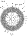
FIG. 2 is a tire side view of the non-pneumatic tire shown inFIG. 1 viewed from an outside of a vehicle body in a tire width direction. -
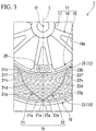
FIG 3 is an enlarged view showing a main portion ofFIG. 2 . -
FIG. 4 is a tire side view of a first divided case body viewed from the outside of the vehicle body in the tire width direction, or a tire side view of a second divided case body viewed from the inside of the vehicle body in the tire width direction, in the non-pneumatic tires shown inFIG. 1 . -
FIG 5 is a side view of a main portion including a ring-shaped body and a tread member viewed from the tire width direction, in the non-pneumatic tire shown inFIG. 1 , and is a view in which the tread member is limited in cross section. -
FIG 6 is a side view of a main portion including a ring-shaped body and a tread member viewed from the tire width direction, in another embodiment of the non-pneumatic tire according to the present invention, and is a view in which the tread member is limited in cross section. -
FIG 7 is an enlarged view showing a main portion ofFIG. 5 . - Hereinafter, an embodiment according to the invention will be described with reference to
FIG. 1 to FIG. 5 . - As shown in
FIG. 1 andFIG. 2 , anon-pneumatic tire 1 of the present embodiment includes anattachment body 11 which is attached to an axle (not shown), a cylindrical ring-shaped body 13 (outer tube body) which surrounds theattachment body 11 from an outside in a tire radial direction, a plurality ofconnection members 15 which are disposed between theattachment body 11 and the ring-shapedbody 13 along a tire peripheral direction and connect theattachment body 11 and the ring-shapedbody 13 to each other to be relatively elastically displaceable, and acylindrical tread member 16 which is externally mounted to the ring-shapedbody 13. - The
non-pneumatic tire 1 of the present embodiment may be used for a two-wheeled vehicle such as a bicycle or the like, may drive in a state of being a camber angle of about 30 degrees, and may be adapted for small vehicles or the like which is defined in Japanese Industrial Standard JIS T 9208 and is driven at a low speed such as a handle type electric wheelchair. In addition, the size of thenon-pneumatic tire 1 is not particularly limited, but may be 3.00 to 8 or the like, for example. In addition, thenon-pneumatic tire 1 may be used for a passenger car. The size, in this case, is not particularly limited, and it may also be, for example, 155/65R13 or the like. - The
attachment body 11, the ring-shaped body 13, and thetread member 16 described above are disposed coaxially with a common shaft, respectively. Hereinafter, this common axis is referred to as an axis O, a direction along the axis O is referred to as the tire width direction H, a direction orthogonal to the axis O is referred to as the tire radial direction, and a direction orbiting around the axis O is referred to as a tire peripheral direction. Theattachment body 11, the ring-shaped body 13, and thetread member 16 are disposed in a state where center portions thereof in the tire width direction H are coincident with each other. In addition, the outer diameter of the ring-shaped body 13 is equal regardless of the position in the tire peripheral direction. - The
attachment body 11 includes amounting tube portion 17 on which a tip portion of the axle is mounted, anouter ring portion 18 which surrounds themounting tube portion 17 from the outside in the tire radial direction, and a plurality ofribs 19 which connects themounting tube portion 17 and theouter ring portion 18 to each other. - The
mounting tube portion 17, theouter ring portion 18, and theribs 19 are integrally formed of a metal material such as an aluminum alloy, for example. Themounting tube portion 17 and theouter ring portion 18 are respectively formed in a cylindrical shape and are disposed coaxially with an axis line O. The plurality ofribs 19 are disposed at an equal interval in the peripheral direction, for example. - On the outer peripheral surface of the
outer ring portion 18, a plurality ofkey groove portions 18a which is depressed inward in the tire radial direction and extends in the tire width direction H are formed at intervals in the tire peripheral direction. Thekey groove portion 18a is open only on the outer side (a first side) of the vehicle body in the tire width direction H on the outer peripheral surface of theouter ring portion 18 and is closed on the inner side (a second side) of the vehicle body in the tire width direction H. - In the
outer ring portion 18, in a portion positioned between the adjacentkey groove portions 18a in the tire peripheral direction, a plurality oflightening holes 18b penetrating theouter ring portion 18 in the tire radial direction are formed at intervals in the tire width direction H. A plurality ofhole rows 18c formed by the plurality of lighteningholes 18b are formed at intervals in the tire peripheral direction. Similarly, eachrib 19 also has alightening hole 19a penetrating therib 19 in the tire width direction H. - A
recessed portion 18d into which theplate material 28 having a throughhole 28a is fitted is formed at a position corresponding to thekey groove portion 18a on an edge of the outer side of the vehicle body in the tire width direction H in theouter ring portion 18. Therecessed portion 18d is recessed toward the inner side of the vehicle body in the tire width direction H. In addition, a female thread portion which communicates with the throughhole 28a of theplate material 28 fitted in the recessedportion 18d is formed on a wall surface of the wall surfaces defining the recessedportion 18d facing the outer side of the vehicle body in the tire width direction H. - A plurality of the
through holes 28a are formed on theplate material 28 at intervals in the tire peripheral direction. - Similarly, a plurality of female thread portions are formed on the wall surface of the
recessed portion 18d at intervals in the tire peripheral direction. In the example shown, two throughholes 28a and two female threaded portions are formed, but the number thereof is not limited to two. - A cylindrical
exterior body 12 is externally fitted to theattachment body 11. Aridge portion 12a protruding inward in the tire radial direction and extending over the entire length in the tire width direction H is formed on the inner peripheral surface of theexterior body 12. A plurality ofridge portions 12a are formed at intervals in the tire peripheral direction on the inner peripheral surface of theexterior body 12 and are fitted respectively in thekey groove portions 18a formed on theattachment body 11. - Then, in a state where the
ridge portion 12a is fitted in thekey groove portion 18a, theexterior body 12 is fixed to theattachment body 11 by a bolt (not shown) being screwed into the female threaded portion through the throughhole 28a of theplate material 28 fitted in the recessedportion 18d. - Of the wall surfaces defining the
key groove portion 18a, a pair of side wall surfaces opposed to each other in the tire peripheral direction and the bottom wall surface are formed so as to be orthogonal to each other. In addition, a pair of side wall surfaces rising from the inner peripheral surface of theexterior body 12 and a top wall surface facing inward in the tire radial direction in the outer surface of theridge portion 12a are also formed to be orthogonal in the same manner. The sizes of theridge portion 12a and thekey groove portion 18a in the tire peripheral direction are equal to each other. - With such a configuration, the
ridge portion 12a is fitted in thekey groove portion 18a with less rattling and high precision. - The
connection member 15 connects the outer peripheral surface side of theattachment body 11 and the inner peripheral surface side of the ring-shaped body 13 to each other to be relatively elastically displaceable. In the example shown, theconnection member 15 includes afirst connection plate 21 and asecond connection plate 22 that connects the outer peripheral surface of theexterior body 12 externally fitted to theattachment body 11 and the inner peripheral surface of the ring-shaped body 13 to each other. Both of thefirst connection plate 21 and thesecond connection plate 22 are elastically deformable plate materials. - A plurality of the
first connection plates 21 are disposed along the tire peripheral direction, at a position on the outer side of the vehicle body along the tire width direction H. A plurality ofsecond connection plates 22 are disposed along the tire peripheral direction, at a position on the inner side of the vehicle body along the tire width direction H. In other words, thefirst connection plate 21 and thesecond connection plate 22 are disposed spaced apart from each other in the tire width direction H and a plurality of thefirst connection plates 21 and thesecond connection plates 22 are disposed at respective positions along the tire peripheral direction. For example, 60first connection plates 21 and 60second connection plates 22 are provided along the tire peripheral direction. - The plurality of
connection members 15 are disposed separately at positions that are rotationally symmetrical about the axis O between theexterior body 12 and the ring-shaped body 13. In addition, all theconnection members 15 have the same shape and the same size to each other, and the lateral width of theconnection member 15 along the tire width direction H is smaller than the lateral width of the ring-shaped body 13 along the tire width direction H. - The
first connection plates 21 adjacent to each other in the tire peripheral direction are not in contact with each other. Similarly, thesecond connection plates 22 adjacent to each other in the tire peripheral direction are also not in contact with each other. In addition, thefirst connection plate 21 and thesecond connection plate 22 adjacent to each other in the tire width direction H are also not in contact with each other. Further, thefirst connection plate 21 and thesecond connection plate 22 have the same lateral width and thickness along the tire width direction H. - As shown in
FIG. 3 , the outer end portion (a first end portion) 21a of thefirst connection plate 21 connected to the ring-shapedbody 13 is positioned on a first side of the inner end portion (a second end portion) 21b connected to theexterior body 12 in the tire peripheral direction. On the other hand, the outer end portion (a first end portion) 22a of thesecond connection plate 22 connected to the ring-shapedbody 13 is positioned on a second side of the inner end portion (the second end portion) 22b connected to theexterior body 12 in the tire peripheral direction. - Each of the
outer end portions first connection plate 21 and thesecond connection plate 22 constituting oneconnection member 15 is connected to the same position in the tire peripheral direction in a state where the positions thereof in the tire width direction H are different from each other on the inner peripheral surface of the ring-shapedbody 13. - In the
first connection plate 21 and thesecond connection plate 22, a plurality ofcurved portions 21d to 21f and 22d to 22f curved in the tire peripheral direction are formed on an intermediate portion positioned between theouter end portions inner end portions - The plurality of
curved portions 21d to 21f and 22d to 22f are formed along the extending direction of thefirst connection plate 21 and thesecond connection plate 22 in a tire side view which is viewed thenon-pneumatic tire 1 from the tire width direction H. In the example shown, the plurality ofcurved portions 21d to 21f in thefirst connection plate 21 and the plurality of curved portions 22d to 22f in thesecond connection plate 22 are formed such that thefirst connection plate 21 and thesecond connection plate 22 are adjacent to each other in an extending direction and the curved directions thereof are opposite to each other. - The plurality of
curved portions 21d to 21f formed on thefirst connection plate 21 include a firstcurved portion 21d which is curved so as to protrude toward the second side in the tire peripheral direction, a secondcurved portion 21e which is positioned between the firstcurved portion 21d and theouter end portion 21a and is curved so as to protrude toward the first side in the tire peripheral direction, and a third curved portion 21f which is positioned between the firstcurved portion 21d and theinner end portion 21 b and is curved so as to protrude toward the first side in the tire peripheral direction. The secondcurved portion 21e is connected to theouter end portion 21a. - The plurality of curved portions 22d to 22f formed on the
second connection plate 22 include a first curved portion 22d which is curved so as to protrude toward the first side in the tire peripheral direction, a secondcurved portion 22e which is positioned between the first curved portion 22d and theouter end portion 22a and is curved so as to protrude toward the second side in the tire peripheral direction, and a thirdcurved portion 22f which is positioned between the first curved portion 22d and theinner end portion 22b and is curved so as to protrude toward the second side in the tire peripheral direction. The secondcurved portion 22e is connected to theouter end portion 22a. - In the example shown, the first
curved portions 21d and 22d are formed to have a larger curvature radius in a tire side view than the secondcurved portions curved portions 21f and 22f, and are disposed on the center portions in an extending direction of thefirst connection plate 21 and thesecond connection plate 22. - The lengths of the
first connection plate 21 and thesecond connection plate 22 are equal to each other. Theinner end portions first connection plate 21 and thesecond connection plate 22 respectively are connected to positions on the outer peripheral surface of theexterior body 12 spaced apart on the first side and the second side by the same distance respectively in the tire peripheral direction about the axis O from a position facing theouter end portions exterior body 12. - Specifically, the
inner end portions first connection plate 21 and thesecond connection plate 22 are connected to the outer peripheral surface of theexterior body 12 so that an angle formed between the line connecting theouter end portion 21a and theinner end portion 21b of thefirst connection plate 21 and the line connecting theouter end portion 22a and theinner end portion 22b of thesecond connection plate 22 has, for example, an angle between 20° and 135°. - In addition, the first
curved portions 21d and 22d, the secondcurved portions curved portions 21f and 22f of thefirst connection plate 21 and thesecond connection plate 22 protrude in the opposite direction of the tire peripheral direction to each other and to the same size, respectively. - With the configuration described above, as shown in
Fig 3 , the shape of each of theconnection members 15 in a tire side view extends along the tire radial direction and is line-symmetrical about a virtual line L which passes through each of theouter end portion first connection plate 21 and thesecond connection plate 22 as a symmetrical axis. - The
exterior body 12, the ring-shapedbody 13, and the plurality ofconnection members 15 described above are integrally formed of a synthetic resin material, for example. The synthetic resin material may be, for example, only one type of resin material, a mixture containing two or more types of resin materials, or a mixture containing at least one type of resin material and at least one type of elastomer and further, may also include an antioxidant, a plasticizer, a filler, or an additive such as a pigment, for example. - Incidentally, as shown in
FIG. 1 , theexterior body 12 is divided into a firstexterior body 25 positioned on the outer side of the vehicle body in the tire width direction H and a secondexterior body 26 positioned on the inner side of the vehicle body in the tire width direction H. Similarly, the ring-shapedbody 13 is divided into a first ring-shaped body 23 (divided tube) positioned on the outer side of the vehicle body in the tire width direction H and a second ring-shaped body 24 (divided tube) positioned on the inner side of the vehicle body in the tire width direction H. In the ring-shapedbody 13, the ends of the first and second ring-shapedbodies 23 and 24 (a plurality of divided tubes) in the tire width direction H disposed adjacent to each other in the tire width direction H are connected to each other. - In the example shown, the
exterior body 12 and the ring-shapedbody 13 are divided at the center portion in the tire width direction H, respectively. - Then, as shown in
FIG. 4 , the firstexterior body 25 and the first ring-shapedbody 23 are integrally formed with thefirst connection plate 21 by injection molding. The secondexterior body 26 and the second ring-shapedbody 24 are integrally formed with thesecond connection plate 22 by injection molding. - Hereinafter, a unit in which the first
exterior body 25, the first ring-shapedbody 23, and thefirst connection plate 21 are integrally formed is referred to as a first dividedcase body 31 and a unit in which the secondexterior body 26, the second ring-shapedbody 24 and thesecond connection plate 22 are integrally formed is referred to as a second dividedcase body 32. - Each of the divided
case bodies connection member 15 side toward the ring-shapedbody 13 side. - As an example, the first divided
case body 31, as a mold, includes a cavity that has an inner space for molding the firstexterior body 25, an outer space for molding the first ring-shapedbody 23, and an intermediate space for molding thefirst connection plate 21 and a gate to the cavity is configured so as to be connected to the inner space. In this mold, the first dividedcase body 31 is formed by the molding material being injected from the gate into the cavity and being supplied from the inner space to the outer space through the intermediate space. At this time, in the intermediate space, the molding material which has passed through each portion forming thefirst connection plate 21 adjacent in the tire peripheral direction flows so as to approach each other in the tire peripheral direction in the outer space based on an injection pressure thereof and thus the weld is formed in the portion of the first ring-shapedbody 23 interposed in the tire peripheral direction between theouter end portions 21a of thefirst connection plates 21 adjacent to each other in the tire peripheral direction. - These points are also similarly applied to the second divided
case body 32. - The edges of the first ring-shaped
body 23 and the second ring-shapedbody 24 facing in the tire width direction H are connected to each other, for example, by welding, fusing, adhesion or the like and a joining portion (not shown) which connects the edges of the first and second ring-shapedbodies body 13. In the case of welding, for example, hot plate welding or the like may be performed. Similarly, the firstexterior body 25 and the secondexterior body 26 are in contact in the edges facing in the tire width direction H. - However, the first
exterior body 25 and the secondexterior body 26 may be formed so that the lateral widths thereof along the tire width direction H is smaller than that of the first ring-shapedbody 23 and the second ring-shapedbody 24. - In this case, in the first
exterior body 25 and the secondexterior body 26, when the first dividedcase body 31 and the second dividedcase body 32 are connected to each other, the edges facing in the tire width direction H are spaced apart from each other in the tire width direction. Therefore, for example, generation of burrs can be prevented on the inner peripheral surface of theexterior body 12 externally fitted to theattachment body 11. - As shown in
FIG. 4 , the first dividedcase body 31 and the second dividedcase body 32 have the same shape and the same size as each other. When the first dividedcase body 31 and the second dividedcase body 32 are integrally connected to each other as described above, in order to make eachconnection member 15 line-symmetrical as seen in a tire side view, the first dividedcase body 31 and the second dividedcase body 32 are aligned with each other in the tire peripheral direction. In addition, in a state where the directions of the first dividedcase body 31 and the second dividedcase body 32 are opposite to each other in the tire width direction H, the edges of the first ring-shapedbody 23 and the second ring-shapedbody 24 in the tire width direction H are collided and connected to each other. - Thereafter, by providing the
tread member 16 to the first dividedcase body 31 and the second dividedcase body 32 integrally combined with each other, thenon-pneumatic tire 1 can be obtained. - As shown in
FIG. 1 , thetread member 16 is formed in a cylindrical shape and integrally covers the entire outer peripheral surface side of the ring-shapedbody 13. The inner diameter of thetread member 16 is equal over the entire periphery thereof, and the inner peripheral surface of thetread member 16 is in close contact with the outer peripheral surface of the ring-shapedbody 13 over the entire area thereof. The inner diameter of thetread member 16 is the distance along the tire radial direction between the inner peripheral surface of thetread member 16 and the axis O. The outer peripheral surface of thetread member 16 is formed in a perfect circular shape in a cross-sectional view taken along an orthogonal plane orthogonal to the axis O and the outer diameter of thetread member 16 is equal over the entire periphery thereof. The outer diameter of thetread member 16 is the distance along the tire radial direction between the outer peripheral surface of thetread member 16 and the axis O. - As shown in
FIG. 5 , thetread member 16 includes abase rubber portion 41 positioned on the inner side in the tire radial direction and acap rubber portion 42 positioned outside of thebase rubber portion 41 in the tire radial direction. Both thebase rubber portion 41 and thecap rubber portion 42 extend over the entire periphery of the ring-shapedbody 13, and thetread member 16 has a two-layer structure of thebase rubber portion 41 and thecap rubber portion 42. - The
base rubber portion 41 is disposed at least in a portion (portion where weld is formed) positioned between theconnection members 15 adjacent in the tire peripheral direction in the ring-shapedbody 13, and in the example shown, as described above extends over the entire periphery of the ring-shapedbody 13. A portion (hereinafter referred to as "weld protecting portion") 41a of thebase rubber portion 41 positioned between theconnection members 15 adjacent to each other in the tire peripheral direction on the outer peripheral surface of the ring-shapedbody 13 is thicker than other portion thereof and is formed to be large in the tire radial direction. In the present embodiment, the portion of the ring-shapedbody 13 positioned between theconnection members 15 adjacent to each other in the tire peripheral direction is a portion of the first ring-shaped body 23 (or second ring-shaped body 24) interposed in the tire peripheral direction by eachouter end portion 21a of the first connection plate 21 (or eachouter end portion 22a of the second connection plate 22) adjacent to each other in the tire peripheral direction. - The
weld protecting portion 41a has a curved surface shape that protrudes toward the outside in the tire radial direction in a cross-sectional view taken along an orthogonal plane orthogonal to the axis O. In the cross-sectional view taken along the orthogonal plane orthogonal to the axis O, the curvature of theouter surface 41b facing the outside in the tire radial direction in theweld protecting portion 41a is larger than the curvature of the outer peripheral surface of thetread member 16. - The thickness (size in the tire radial direction) of the excluded portion which is a portion of the
base rubber portion 41 other than theweld protecting portion 41a is the same regardless of the position in the tire radial direction. - In addition, when the lateral width in the tire peripheral direction of the
weld protecting portion 41a of thebase rubber portion 41 is referred to as A and the distance between theweld protecting portions 41 a in the tire peripheral direction is referred to as B, the distance B between theweld protecting portions 41 a is longer than the lateral width A of theweld protecting portion 41 a. - The
cap rubber portion 42 covers thebase rubber portion 41 from the outside to the entire periphery thereof in the tire radial direction, and thebase rubber portion 41 is not exposed to the outside in the tire radial direction. The outer peripheral surface of thecap rubber portion 42 constitutes the outer peripheral surface of thetread member 16. - Here, the
base rubber portion 41 and thecap rubber portion 42 are made of two types of rubbers which are different from each other. Thebase rubber portion 41 and thecap rubber portion 42 are formed of vulcanized rubber in which natural rubber and/or a rubber composition are vulcanized. The rigidity of thebase rubber portion 41 is lower than the rigidity of thecap rubber portion 42. In the present embodiment, the rubber hardness Gb of thebase rubber portion 41 is lower than the rubber hardness Gc of thecap rubber portion 42. The rubber hardness Gb of thebase rubber portion 41 and the rubber hardness Gc of thecap rubber portion 42 satisfy 30<Gb<Gc<80. The rubber hardness (Japanese Industrial Standard JIS-A hardness) was measured by a durometer A in accordance with Japanese Industrial Standard JIS K 6253. In addition, the elastic modulus Eb of thebase rubber portion 41 is lower than the elastic modulus Ec of thecap rubber portion 42. The elastic modulus Eb of thebase rubber portion 41 and the elastic modulus Ec of thecap rubber portion 42 satisfy 0.1 MPa<Eb<Ec<100 MPa. The elastic modulus was measured by a tensile tester according to Japanese Industrial Standard JIS K 6254: 2010. - As described above, according to the
non-pneumatic tire 1 according to the present embodiment, since the rigidity of thebase rubber portion 41 positioned on the inner side in the tire radial direction is lower than the rigidity of thecap rubber portion 42 positioned outside in the tire radial direction, the stress generated in thetread member 16 can be dispersed in thebase rubber portion 41 when a load is applied to thetread member 16. Since thebase rubber portion 41 is disposed at least in a portion positioned between theconnection members 15 adjacent to each other in the tire peripheral direction in the ring-shapedbody 13, by dispersing the stress as described above, the stress transferred from thetread member 16 to the weld can be suppressed. - On the other hand, since the
cap rubber portion 42 having high rigidity is positioned outside in the tire radial direction with respect to thebase rubber portion 41 having low rigidity, wear resistance and impact resistance of thetread member 16 can be secured by thecap rubber portion 42 and the driving stability of thenon-pneumatic tire 1 can also be secured. - As described above, while the stress transferred to the weld is suppressed by the
base rubber portion 41, the wear resistance, the impact resistance of thetread member 16 can be secured by thecap rubber portion 42 and thus the strength of thenon-pneumatic tire 1 can be improved. - In addition, since the
base rubber portion 41 extends over the entire periphery of the outer peripheral surface of the ring-shapedbody 13 and theweld protecting portion 41a of thebase rubber portion 41 is thicker than the other portions, the stress can be effectively dispersed in a wide range in theweld protecting portion 41a in the tire peripheral direction. - In addition, since the rubber hardness Gb of the
base rubber portion 41 is lower than the rubber hardness Gc of thecap rubber portion 42, stress generated in thetread member 16 can be effectively dispersed in thebase rubber portion 41. - Furthermore, since the rubber hardness Gb of the
base rubber portion 41 and the rubber hardness Gc of thecap rubber portion 42 satisfy 30<Gb<Gc<80, the stress generated in thetread member 16 can be more effectively dispersed in thebase rubber portion 41. - In addition, since the elastic modulus Eb of the
base rubber portion 41 is lower than the elastic modulus Ec of thecap rubber portion 42, stress generated in thetread member 16 can be effectively dispersed in thebase rubber portion 41. - Furthermore, since the elastic modulus Eb of the
base rubber portion 41 and the elastic modulus Ec of thecap rubber portion 42 satisfy 0.1 MPa<Eb<Ec<100 MPa, the stress generated in thetread member 16 ca be more effective dispersed in thebase rubber portion 41. - The technical scope of the invention is not limited to the above embodiment, and various modifications can be made without departing from the scope of the invention.
- For example, in the present invention, it is also possible to use a non-pneumatic tire as shown in
FIG. 6 . In this non-pneumatic tire, thebase rubber portion 41 is disposed only in portions of the ring-shapedbody 13 positioned between theconnection members 15 adjacent to each other in the tire peripheral direction. A plurality of thebase rubber portions 41 are intermittently disposed in the tire peripheral direction. Each one of thebase rubber portions 41 has a curved surface shape protruding toward the outside in the tire radial direction in a cross-sectional view taken along an orthogonal plane orthogonal to an axis O. - In the cross-sectional view taken along the orthogonal plane orthogonal to the axis O, the curvature of the outer surface of each one of the
base rubber portions 41 facing the outside in the tire radial direction is larger than the curvature of the outer peripheral surface of thetread member 16. - For example, in the above embodiment, there is shown a configuration in which each of one
first connection plate 21 and onesecond connection plate 22 is provided as theconnection member 15, but, instead of this, a plurality offirst connection plates 21 and a plurality ofsecond connection plates 22 may be provided for oneconnection members 15 so that positions thereof in the tire width direction H are different from each other. In addition, a plurality ofconnection members 15 may be provided between theexterior body 12 and the ring-shapedbody 13 along the tire width direction H. - In addition, instead of the above embodiment, the
inner end portions first connection plate 21 and thesecond connection plate 22 may be respectively connected to positions opposite to each other, for example, interposing the axis O in the outer peripheral surface of theexterior body 12 in the tire radial direction. Alternatively, on the outer peripheral surface of theexterior body 12, theinner end portions first connection plate 21 and thesecond connection plate 22 may be connected to a position opposing to each of theouter end portions first connection plate 21 and thesecond connection plate 22 in the tire radial direction. In addition, instead of the above embodiment, theouter end portions first connection plate 21 and thesecond connection plate 22 may be respectively connected to different positions from each other in the tire peripheral direction in the inner peripheral surface of the ring-shapedbody 13. - Furthermore, in the above embodiment, a gap in the tire width direction H may be provided or may not be provided between the first
exterior body 25 and the secondexterior body 26. In addition, theexterior body 12 and the ring-shapedbody 13 may be divided or may not be divided into three or more in the tire width direction H. - In addition, the
exterior body 12 and theattachment body 11 may be integrally formed. In other words, theexterior body 12 may be included in theattachment body 11. - Furthermore, in the embodiment described above, the
connection member 15 is indirectly connected to theattachment body 11 via theexterior body 12, but it is not limited thereto. For example, theconnection member 15 may be directly connected to theattachment body 11. - Besides, each configuration (constituent elements) described in the embodiment described above, modification example, and still further writing may be combined with each other without departing from the scope of the invention and in addition, additions, omissions, substitutions, and other changes to the configuration are possible. In addition, the invention is not limited to the embodiments described above and is limited only by the claims.
- Next, a verification test on the operational effects described above was carried out.
- As an example, the
non-pneumatic tire 1 shown inFIGS. 1 to 5 was used, and as a comparative example, a non-pneumatic tire in which thetread member 16 has a single layer structure made of the same material as thecap rubber portion 42 is used in the non-pneumatic tire of the example. - As shown in
FIG. 7 , the thickness of the ring-shapedbody 13 of these non-pneumatic tires is set to H1, the thickness of the excluded portion of thebase rubber portion 41 is set to H2a, the thickness of theweld protecting portion 41a of thebase rubber portion 41 is set to H2b and the thickness of thecap rubber portion 42 is set to H3. The thickness H1 of the ring-shapedbody 13 is larger than the thickness H2a of the excluded portion of thebase rubber portion 41, the thickness H2b of theweld protecting portion 41a of thebase rubber portion 41, and the thickness H3 of thecap rubber portion 42, that is, the relationship which is H1>H2a, H2b, H3 is established. Further, the thickness H1 of the ring-shapedbody 13 is equal to or larger than the sum of the thickness H2a of the excluded portion of thebase rubber portion 41 and the thickness H3 of thecap rubber portion 42 or is equal to or greater than the sum of the thickness H2b of theweld protecting portion 41a of thebase rubber portion 41 and the thickness H3 of thecap rubber portion 42, that is, the relationship which is H1≥H2a+H3 or H1≥H2b+H3 is established. - The outer diameters of these non-pneumatic tires and each dimension of H1, H2a, H2b, and H3 were set to the sizes shown in Table 1 below. The unit of the value described in the second line of Table 1 is mm.
[Table 1] Tire Outer Diameter R H1 H2a H2b H3 150 6 2 4 4 (unit: mm) - The rubber hardness and elastic modulus of the
base rubber portion 41 and thecap rubber portion 42 in thenon-pneumatic tire 1 of the example were set to the sizes shown in Table 2 below.[Table 2] Base Rubber Portion Cap Rubber Portion Rubber Hardness 60 65 Elasticity Modulus (MPa) 35 40 - For these two types of non-pneumatic tires, the driving distance was measured until the tire was broken by using a drum tester and driving at 60 km/h in a state where a load of 1000 N is applied.
- As a result, it was confirmed that the driving distance was increased by 20% in the
non-pneumatic tire 1 of the example compared to the non-pneumatic tire of the comparative example,. - According to the present invention, the strength of the non-pneumatic tire can be improved.
-
- 1 non-pneumatic tire
- 11 attachment body
- 13 ring-shaped body (outer tube body)
- 15 connection member
- 16 tread member
- 41 base rubber portion
- 42 cap rubber portion
Claims (8)
- A non-pneumatic tire comprising:an attachment body that is attached to an axle;an outer tube body that surrounds the attachment body from an outside in a tire radial direction;a plurality of connection members that are disposed between the attachment body and the outer tube body along a tire peripheral direction and connect the attachment body and the outer tube body to each other; anda cylindrical tread member that is externally mounted on the outer tube body,wherein the outer tube body and the connection member are integrally formed by an injection molding in which a molding material is injected from the connection member side toward the outer tube body side,wherein the tread member includes a base rubber portion that is positioned at an inside in the tire radial direction and a cap rubber portion that is positioned at an outside of the base rubber portion in the tire radial direction,wherein rigidity of the base rubber portion is lower than rigidity of the cap rubber portion, andwherein the base rubber portion is disposed at least in a portion positioned between the connection members adjacent to each other in the tire peripheral direction in the outer tube body.
- The non-pneumatic tire according to claim 1,
wherein the base rubber portion extends over the entire periphery of the outer tube body, and
wherein a portion, in the base rubber portion, which is positioned between the connection members adjacent to each other in the tire peripheral direction on an outer peripheral surface of the outer tube body is thicker than other portions of the base rubber portion. - The non-pneumatic tire according to claim 1,
wherein the rubber hardness Gb of the base rubber portion is lower than the rubber hardness Gc of the cap rubber portion. - The non-pneumatic tire according to claim 2,
wherein the rubber hardness Gb of the base rubber portion is lower than the rubber hardness Gc of the cap rubber portion. - The non-pneumatic tire according to claim 3,
wherein the rubber hardness Gb of the base rubber portion and the rubber hardness Gc of the cap rubber portion satisfy 30<Gb<Gc<80. - The non-pneumatic tire according to claim 4,
wherein the rubber hardness Gb of the base rubber portion and the rubber hardness Gc of the cap rubber portion satisfy 30<Gb<Gc<80. - The non-pneumatic tire according to any one of claims 1 to 6,
wherein the elastic modulus Eb of the base rubber portion is lower than the elastic modulus Ec of the cap rubber portion. - The non-pneumatic tire according to claim 7,
wherein the elastic modulus Eb of the base rubber portion and the elastic modulus Ec of the cap rubber portion satisfy 0.1 MPa<Eb<Ec<100 MPa.
Applications Claiming Priority (2)
| Application Number | Priority Date | Filing Date | Title |
|---|---|---|---|
| JP2015005720 | 2015-01-15 | ||
| PCT/JP2016/050091 WO2016114167A1 (en) | 2015-01-15 | 2016-01-05 | Non-pneumatic tire |
Publications (3)
| Publication Number | Publication Date |
|---|---|
| EP3246180A1 true EP3246180A1 (en) | 2017-11-22 |
| EP3246180A4 EP3246180A4 (en) | 2018-03-14 |
| EP3246180B1 EP3246180B1 (en) | 2019-06-26 |
Family
ID=56405714
Family Applications (1)
| Application Number | Title | Priority Date | Filing Date |
|---|---|---|---|
| EP16737238.2A Active EP3246180B1 (en) | 2015-01-15 | 2016-01-05 | Non-pneumatic wheel |
Country Status (5)
| Country | Link |
|---|---|
| US (1) | US20180001699A1 (en) |
| EP (1) | EP3246180B1 (en) |
| JP (1) | JP6727135B2 (en) |
| CN (1) | CN107206841B (en) |
| WO (1) | WO2016114167A1 (en) |
Families Citing this family (16)
| Publication number | Priority date | Publication date | Assignee | Title |
|---|---|---|---|---|
| WO2014201368A1 (en) | 2013-06-15 | 2014-12-18 | Ronald Thompson | Annular ring and non-pneumatic tire |
| WO2016126983A1 (en) | 2015-02-04 | 2016-08-11 | Advancing Mobility, Llc. | Non-pneumatic tire and other annular devices |
| EP3318417A4 (en) * | 2015-07-03 | 2018-07-25 | Bridgestone Corporation | Tire |
| JP2018079886A (en) * | 2016-11-18 | 2018-05-24 | 株式会社ブリヂストン | Non-pneumatic tire and two-wheeled vehicle |
| JP2018083458A (en) * | 2016-11-21 | 2018-05-31 | 株式会社ブリヂストン | Pneumatic tire and two wheel vehicle |
| EP3638515B1 (en) | 2017-06-15 | 2023-04-05 | Camso Inc. | Wheel comprising a non-pneumatic tire |
| CN111344161B (en) | 2017-11-10 | 2022-03-22 | 株式会社普利司通 | Non-pneumatic tire |
| WO2020051715A1 (en) * | 2018-09-14 | 2020-03-19 | Camso Inc. | Non-pneumatic tire for camber-steered vehicle or other vehicle |
| US20220010102A1 (en) * | 2018-11-22 | 2022-01-13 | Bridgestone Corporation | Tire |
| JP7123771B2 (en) * | 2018-11-30 | 2022-08-23 | 株式会社ブリヂストン | non-pneumatic tire |
| CN113226799A (en) * | 2019-01-04 | 2021-08-06 | 普利司通美国轮胎运营有限责任公司 | Tire tread with belt layer |
| KR102103781B1 (en) * | 2019-06-10 | 2020-04-23 | 김민수 | Airless wheel |
| JP2020199954A (en) * | 2019-06-12 | 2020-12-17 | 株式会社ブリヂストン | Non-pneumatic tire, movable body power supply device and movable body |
| CN111003212A (en) * | 2019-12-20 | 2020-04-14 | 北京工业大学 | Mars tire with shape memory alloy lattice structure |
| JP2022104244A (en) * | 2020-12-28 | 2022-07-08 | Toyo Tire株式会社 | Non-pneumatic tire |
| AU2022329736A1 (en) * | 2021-08-17 | 2023-12-07 | Briggs And Riley Travelware, Llc | Shock absorbing luggage wheel |
Family Cites Families (11)
| Publication number | Priority date | Publication date | Assignee | Title |
|---|---|---|---|---|
| JPS5436365B2 (en) * | 1971-11-10 | 1979-11-08 | ||
| JPS59128001A (en) * | 1983-01-12 | 1984-07-24 | Sumitomo Rubber Ind Ltd | Solid tire |
| JPS6018407A (en) * | 1984-06-20 | 1985-01-30 | Sumitomo Rubber Ind Ltd | Solid tire |
| US8109308B2 (en) * | 2007-03-27 | 2012-02-07 | Resilient Technologies LLC. | Tension-based non-pneumatic tire |
| US9662939B2 (en) * | 2009-07-28 | 2017-05-30 | Bridgestone Americas Tire Operations, Llc | Tension-based non-pneumatic tire |
| KR101116869B1 (en) * | 2009-12-02 | 2012-03-06 | 한국타이어 주식회사 | Magnetorheological non pneumatic tire |
| JP5436365B2 (en) * | 2010-08-09 | 2014-03-05 | 東洋ゴム工業株式会社 | Non-pneumatic tire |
| CN202378621U (en) * | 2011-12-21 | 2012-08-15 | 陕西重型汽车有限公司 | Honeycomb-shaped non-inflatable tire assembly |
| CN202518038U (en) * | 2012-01-12 | 2012-11-07 | 周文州 | Aeration-free anti-explosion tire |
| JP6061625B2 (en) * | 2012-11-05 | 2017-01-18 | 株式会社ブリヂストン | Non pneumatic tire |
| CN203078232U (en) * | 2013-01-17 | 2013-07-24 | 齐效荣 | Non-inflation reticular tire with steel structure in rubber structure |
-
2016
- 2016-01-05 CN CN201680005807.1A patent/CN107206841B/en active Active
- 2016-01-05 WO PCT/JP2016/050091 patent/WO2016114167A1/en active Application Filing
- 2016-01-05 EP EP16737238.2A patent/EP3246180B1/en active Active
- 2016-01-05 JP JP2016569306A patent/JP6727135B2/en active Active
- 2016-01-05 US US15/543,066 patent/US20180001699A1/en not_active Abandoned
Also Published As
| Publication number | Publication date |
|---|---|
| JP6727135B2 (en) | 2020-07-22 |
| EP3246180A4 (en) | 2018-03-14 |
| JPWO2016114167A1 (en) | 2017-10-26 |
| WO2016114167A1 (en) | 2016-07-21 |
| CN107206841A (en) | 2017-09-26 |
| CN107206841B (en) | 2019-12-27 |
| US20180001699A1 (en) | 2018-01-04 |
| EP3246180B1 (en) | 2019-06-26 |
Similar Documents
| Publication | Publication Date | Title |
|---|---|---|
| EP3246180B1 (en) | Non-pneumatic wheel | |
| EP3246178B1 (en) | Non-pneumatic tire | |
| US20170341464A1 (en) | Non-pneumatic tire | |
| JP6746598B2 (en) | Non-pneumatic tire | |
| US10486462B2 (en) | Non-pneumatic tire | |
| US10399381B2 (en) | Non-pneumatic tire | |
| US20140251518A1 (en) | Non-pneumatic tire | |
| US20190009611A1 (en) | Non-pneumatic tire | |
| JP6152036B2 (en) | Non pneumatic tire | |
| US10744821B2 (en) | Non-pneumatic tire | |
| JP6106428B2 (en) | Non pneumatic tire | |
| US20160272006A1 (en) | Non-pneumatic tire | |
| WO2016084512A1 (en) | Non-pneumatic tire | |
| JP2014125081A (en) | Non-pneumatic tire | |
| US20160236514A1 (en) | Non-pneumatic tire | |
| WO2015072183A1 (en) | Non-pneumatic tire | |
| JP6591882B2 (en) | Non-pneumatic tire and method for producing non-pneumatic tire | |
| JP2014213789A (en) | Non-pneumatic tire | |
| JP6522936B2 (en) | Non pneumatic tire | |
| JP6522931B2 (en) | Non pneumatic tire | |
| JP2015096384A (en) | Non-pneumatic tire |
Legal Events
| Date | Code | Title | Description |
|---|---|---|---|
| STAA | Information on the status of an ep patent application or granted ep patent |
Free format text: STATUS: THE INTERNATIONAL PUBLICATION HAS BEEN MADE |
|
| PUAI | Public reference made under article 153(3) epc to a published international application that has entered the european phase |
Free format text: ORIGINAL CODE: 0009012 |
|
| STAA | Information on the status of an ep patent application or granted ep patent |
Free format text: STATUS: REQUEST FOR EXAMINATION WAS MADE |
|
| 17P | Request for examination filed |
Effective date: 20170717 |
|
| AK | Designated contracting states |
Kind code of ref document: A1 Designated state(s): AL AT BE BG CH CY CZ DE DK EE ES FI FR GB GR HR HU IE IS IT LI LT LU LV MC MK MT NL NO PL PT RO RS SE SI SK SM TR |
|
| AX | Request for extension of the european patent |
Extension state: BA ME |
|
| A4 | Supplementary search report drawn up and despatched |
Effective date: 20180212 |
|
| RIC1 | Information provided on ipc code assigned before grant |
Ipc: B60C 7/14 20060101ALI20180206BHEP Ipc: B60C 11/00 20060101AFI20180206BHEP Ipc: B60B 9/04 20060101ALI20180206BHEP Ipc: B60C 7/24 20060101ALI20180206BHEP Ipc: B60C 7/00 20060101ALI20180206BHEP |
|
| DAV | Request for validation of the european patent (deleted) | ||
| DAX | Request for extension of the european patent (deleted) | ||
| GRAJ | Information related to disapproval of communication of intention to grant by the applicant or resumption of examination proceedings by the epo deleted |
Free format text: ORIGINAL CODE: EPIDOSDIGR1 |
|
| STAA | Information on the status of an ep patent application or granted ep patent |
Free format text: STATUS: GRANT OF PATENT IS INTENDED |
|
| GRAP | Despatch of communication of intention to grant a patent |
Free format text: ORIGINAL CODE: EPIDOSNIGR1 |
|
| INTG | Intention to grant announced |
Effective date: 20190117 |
|
| GRAS | Grant fee paid |
Free format text: ORIGINAL CODE: EPIDOSNIGR3 |
|
| GRAA | (expected) grant |
Free format text: ORIGINAL CODE: 0009210 |
|
| STAA | Information on the status of an ep patent application or granted ep patent |
Free format text: STATUS: THE PATENT HAS BEEN GRANTED |
|
| AK | Designated contracting states |
Kind code of ref document: B1 Designated state(s): AL AT BE BG CH CY CZ DE DK EE ES FI FR GB GR HR HU IE IS IT LI LT LU LV MC MK MT NL NO PL PT RO RS SE SI SK SM TR |
|
| REG | Reference to a national code |
Ref country code: GB Ref legal event code: FG4D |
|
| REG | Reference to a national code |
Ref country code: CH Ref legal event code: EP |
|
| REG | Reference to a national code |
Ref country code: AT Ref legal event code: REF Ref document number: 1147846 Country of ref document: AT Kind code of ref document: T Effective date: 20190715 |
|
| REG | Reference to a national code |
Ref country code: DE Ref legal event code: R096 Ref document number: 602016015958 Country of ref document: DE |
|
| REG | Reference to a national code |
Ref country code: IE Ref legal event code: FG4D |
|
| REG | Reference to a national code |
Ref country code: NL Ref legal event code: MP Effective date: 20190626 |
|
| PG25 | Lapsed in a contracting state [announced via postgrant information from national office to epo] |
Ref country code: HR Free format text: LAPSE BECAUSE OF FAILURE TO SUBMIT A TRANSLATION OF THE DESCRIPTION OR TO PAY THE FEE WITHIN THE PRESCRIBED TIME-LIMIT Effective date: 20190626 Ref country code: AL Free format text: LAPSE BECAUSE OF FAILURE TO SUBMIT A TRANSLATION OF THE DESCRIPTION OR TO PAY THE FEE WITHIN THE PRESCRIBED TIME-LIMIT Effective date: 20190626 Ref country code: SE Free format text: LAPSE BECAUSE OF FAILURE TO SUBMIT A TRANSLATION OF THE DESCRIPTION OR TO PAY THE FEE WITHIN THE PRESCRIBED TIME-LIMIT Effective date: 20190626 Ref country code: FI Free format text: LAPSE BECAUSE OF FAILURE TO SUBMIT A TRANSLATION OF THE DESCRIPTION OR TO PAY THE FEE WITHIN THE PRESCRIBED TIME-LIMIT Effective date: 20190626 Ref country code: NO Free format text: LAPSE BECAUSE OF FAILURE TO SUBMIT A TRANSLATION OF THE DESCRIPTION OR TO PAY THE FEE WITHIN THE PRESCRIBED TIME-LIMIT Effective date: 20190926 Ref country code: LT Free format text: LAPSE BECAUSE OF FAILURE TO SUBMIT A TRANSLATION OF THE DESCRIPTION OR TO PAY THE FEE WITHIN THE PRESCRIBED TIME-LIMIT Effective date: 20190626 |
|
| REG | Reference to a national code |
Ref country code: LT Ref legal event code: MG4D |
|
| PG25 | Lapsed in a contracting state [announced via postgrant information from national office to epo] |
Ref country code: RS Free format text: LAPSE BECAUSE OF FAILURE TO SUBMIT A TRANSLATION OF THE DESCRIPTION OR TO PAY THE FEE WITHIN THE PRESCRIBED TIME-LIMIT Effective date: 20190626 Ref country code: BG Free format text: LAPSE BECAUSE OF FAILURE TO SUBMIT A TRANSLATION OF THE DESCRIPTION OR TO PAY THE FEE WITHIN THE PRESCRIBED TIME-LIMIT Effective date: 20190926 Ref country code: LV Free format text: LAPSE BECAUSE OF FAILURE TO SUBMIT A TRANSLATION OF THE DESCRIPTION OR TO PAY THE FEE WITHIN THE PRESCRIBED TIME-LIMIT Effective date: 20190626 Ref country code: GR Free format text: LAPSE BECAUSE OF FAILURE TO SUBMIT A TRANSLATION OF THE DESCRIPTION OR TO PAY THE FEE WITHIN THE PRESCRIBED TIME-LIMIT Effective date: 20190927 |
|
| REG | Reference to a national code |
Ref country code: AT Ref legal event code: MK05 Ref document number: 1147846 Country of ref document: AT Kind code of ref document: T Effective date: 20190626 |
|
| PG25 | Lapsed in a contracting state [announced via postgrant information from national office to epo] |
Ref country code: AT Free format text: LAPSE BECAUSE OF FAILURE TO SUBMIT A TRANSLATION OF THE DESCRIPTION OR TO PAY THE FEE WITHIN THE PRESCRIBED TIME-LIMIT Effective date: 20190626 Ref country code: NL Free format text: LAPSE BECAUSE OF FAILURE TO SUBMIT A TRANSLATION OF THE DESCRIPTION OR TO PAY THE FEE WITHIN THE PRESCRIBED TIME-LIMIT Effective date: 20190626 Ref country code: EE Free format text: LAPSE BECAUSE OF FAILURE TO SUBMIT A TRANSLATION OF THE DESCRIPTION OR TO PAY THE FEE WITHIN THE PRESCRIBED TIME-LIMIT Effective date: 20190626 Ref country code: RO Free format text: LAPSE BECAUSE OF FAILURE TO SUBMIT A TRANSLATION OF THE DESCRIPTION OR TO PAY THE FEE WITHIN THE PRESCRIBED TIME-LIMIT Effective date: 20190626 Ref country code: CZ Free format text: LAPSE BECAUSE OF FAILURE TO SUBMIT A TRANSLATION OF THE DESCRIPTION OR TO PAY THE FEE WITHIN THE PRESCRIBED TIME-LIMIT Effective date: 20190626 Ref country code: SK Free format text: LAPSE BECAUSE OF FAILURE TO SUBMIT A TRANSLATION OF THE DESCRIPTION OR TO PAY THE FEE WITHIN THE PRESCRIBED TIME-LIMIT Effective date: 20190626 Ref country code: PT Free format text: LAPSE BECAUSE OF FAILURE TO SUBMIT A TRANSLATION OF THE DESCRIPTION OR TO PAY THE FEE WITHIN THE PRESCRIBED TIME-LIMIT Effective date: 20191028 |
|
| PG25 | Lapsed in a contracting state [announced via postgrant information from national office to epo] |
Ref country code: IS Free format text: LAPSE BECAUSE OF FAILURE TO SUBMIT A TRANSLATION OF THE DESCRIPTION OR TO PAY THE FEE WITHIN THE PRESCRIBED TIME-LIMIT Effective date: 20191026 Ref country code: IT Free format text: LAPSE BECAUSE OF FAILURE TO SUBMIT A TRANSLATION OF THE DESCRIPTION OR TO PAY THE FEE WITHIN THE PRESCRIBED TIME-LIMIT Effective date: 20190626 Ref country code: SM Free format text: LAPSE BECAUSE OF FAILURE TO SUBMIT A TRANSLATION OF THE DESCRIPTION OR TO PAY THE FEE WITHIN THE PRESCRIBED TIME-LIMIT Effective date: 20190626 Ref country code: ES Free format text: LAPSE BECAUSE OF FAILURE TO SUBMIT A TRANSLATION OF THE DESCRIPTION OR TO PAY THE FEE WITHIN THE PRESCRIBED TIME-LIMIT Effective date: 20190626 |
|
| PG25 | Lapsed in a contracting state [announced via postgrant information from national office to epo] |
Ref country code: TR Free format text: LAPSE BECAUSE OF FAILURE TO SUBMIT A TRANSLATION OF THE DESCRIPTION OR TO PAY THE FEE WITHIN THE PRESCRIBED TIME-LIMIT Effective date: 20190626 |
|
| PG25 | Lapsed in a contracting state [announced via postgrant information from national office to epo] |
Ref country code: DK Free format text: LAPSE BECAUSE OF FAILURE TO SUBMIT A TRANSLATION OF THE DESCRIPTION OR TO PAY THE FEE WITHIN THE PRESCRIBED TIME-LIMIT Effective date: 20190626 Ref country code: PL Free format text: LAPSE BECAUSE OF FAILURE TO SUBMIT A TRANSLATION OF THE DESCRIPTION OR TO PAY THE FEE WITHIN THE PRESCRIBED TIME-LIMIT Effective date: 20190626 |
|
| PG25 | Lapsed in a contracting state [announced via postgrant information from national office to epo] |
Ref country code: IS Free format text: LAPSE BECAUSE OF FAILURE TO SUBMIT A TRANSLATION OF THE DESCRIPTION OR TO PAY THE FEE WITHIN THE PRESCRIBED TIME-LIMIT Effective date: 20200224 |
|
| REG | Reference to a national code |
Ref country code: DE Ref legal event code: R097 Ref document number: 602016015958 Country of ref document: DE |
|
| PLBE | No opposition filed within time limit |
Free format text: ORIGINAL CODE: 0009261 |
|
| STAA | Information on the status of an ep patent application or granted ep patent |
Free format text: STATUS: NO OPPOSITION FILED WITHIN TIME LIMIT |
|
| PG2D | Information on lapse in contracting state deleted |
Ref country code: IS |
|
| 26N | No opposition filed |
Effective date: 20200603 |
|
| PG25 | Lapsed in a contracting state [announced via postgrant information from national office to epo] |
Ref country code: MC Free format text: LAPSE BECAUSE OF FAILURE TO SUBMIT A TRANSLATION OF THE DESCRIPTION OR TO PAY THE FEE WITHIN THE PRESCRIBED TIME-LIMIT Effective date: 20190626 Ref country code: SI Free format text: LAPSE BECAUSE OF FAILURE TO SUBMIT A TRANSLATION OF THE DESCRIPTION OR TO PAY THE FEE WITHIN THE PRESCRIBED TIME-LIMIT Effective date: 20190626 |
|
| REG | Reference to a national code |
Ref country code: CH Ref legal event code: PL |
|
| GBPC | Gb: european patent ceased through non-payment of renewal fee |
Effective date: 20200105 |
|
| REG | Reference to a national code |
Ref country code: BE Ref legal event code: MM Effective date: 20200131 |
|
| PG25 | Lapsed in a contracting state [announced via postgrant information from national office to epo] |
Ref country code: GB Free format text: LAPSE BECAUSE OF NON-PAYMENT OF DUE FEES Effective date: 20200105 Ref country code: LU Free format text: LAPSE BECAUSE OF NON-PAYMENT OF DUE FEES Effective date: 20200105 |
|
| PG25 | Lapsed in a contracting state [announced via postgrant information from national office to epo] |
Ref country code: CH Free format text: LAPSE BECAUSE OF NON-PAYMENT OF DUE FEES Effective date: 20200131 Ref country code: BE Free format text: LAPSE BECAUSE OF NON-PAYMENT OF DUE FEES Effective date: 20200131 Ref country code: LI Free format text: LAPSE BECAUSE OF NON-PAYMENT OF DUE FEES Effective date: 20200131 |
|
| PG25 | Lapsed in a contracting state [announced via postgrant information from national office to epo] |
Ref country code: IE Free format text: LAPSE BECAUSE OF NON-PAYMENT OF DUE FEES Effective date: 20200105 |
|
| PG25 | Lapsed in a contracting state [announced via postgrant information from national office to epo] |
Ref country code: MT Free format text: LAPSE BECAUSE OF FAILURE TO SUBMIT A TRANSLATION OF THE DESCRIPTION OR TO PAY THE FEE WITHIN THE PRESCRIBED TIME-LIMIT Effective date: 20190626 Ref country code: CY Free format text: LAPSE BECAUSE OF FAILURE TO SUBMIT A TRANSLATION OF THE DESCRIPTION OR TO PAY THE FEE WITHIN THE PRESCRIBED TIME-LIMIT Effective date: 20190626 |
|
| PG25 | Lapsed in a contracting state [announced via postgrant information from national office to epo] |
Ref country code: MK Free format text: LAPSE BECAUSE OF FAILURE TO SUBMIT A TRANSLATION OF THE DESCRIPTION OR TO PAY THE FEE WITHIN THE PRESCRIBED TIME-LIMIT Effective date: 20190626 |
|
| PGFP | Annual fee paid to national office [announced via postgrant information from national office to epo] |
Ref country code: FR Payment date: 20230124 Year of fee payment: 8 |
|
| P01 | Opt-out of the competence of the unified patent court (upc) registered |
Effective date: 20230531 |
|
| PGFP | Annual fee paid to national office [announced via postgrant information from national office to epo] |
Ref country code: DE Payment date: 20240119 Year of fee payment: 9 |