EP3245977A1 - Interdental cleaning instrument - Google Patents
Interdental cleaning instrument Download PDFInfo
- Publication number
- EP3245977A1 EP3245977A1 EP15877880.3A EP15877880A EP3245977A1 EP 3245977 A1 EP3245977 A1 EP 3245977A1 EP 15877880 A EP15877880 A EP 15877880A EP 3245977 A1 EP3245977 A1 EP 3245977A1
- Authority
- EP
- European Patent Office
- Prior art keywords
- cleaning
- end section
- shaft part
- shape
- base
- Prior art date
- Legal status (The legal status is an assumption and is not a legal conclusion. Google has not performed a legal analysis and makes no representation as to the accuracy of the status listed.)
- Granted
Links
- 238000004140 cleaning Methods 0.000 title claims abstract description 177
- 238000003780 insertion Methods 0.000 claims abstract description 55
- 230000037431 insertion Effects 0.000 claims abstract description 55
- 238000006073 displacement reaction Methods 0.000 claims description 28
- 229920001971 elastomer Polymers 0.000 claims description 15
- 239000000806 elastomer Substances 0.000 claims description 15
- 210000000214 mouth Anatomy 0.000 description 15
- PPBRXRYQALVLMV-UHFFFAOYSA-N Styrene Chemical compound C=CC1=CC=CC=C1 PPBRXRYQALVLMV-UHFFFAOYSA-N 0.000 description 8
- 238000011156 evaluation Methods 0.000 description 7
- 238000000034 method Methods 0.000 description 7
- 230000002093 peripheral effect Effects 0.000 description 6
- -1 polypropylene Polymers 0.000 description 6
- 239000004743 Polypropylene Substances 0.000 description 3
- 238000010586 diagram Methods 0.000 description 3
- 229920001707 polybutylene terephthalate Polymers 0.000 description 3
- 229920001155 polypropylene Polymers 0.000 description 3
- 229920003002 synthetic resin Polymers 0.000 description 3
- 239000000057 synthetic resin Substances 0.000 description 3
- 229920000122 acrylonitrile butadiene styrene Polymers 0.000 description 2
- 230000006735 deficit Effects 0.000 description 2
- 230000000694 effects Effects 0.000 description 2
- 229920001296 polysiloxane Polymers 0.000 description 2
- WZFUQSJFWNHZHM-UHFFFAOYSA-N 2-[4-[2-(2,3-dihydro-1H-inden-2-ylamino)pyrimidin-5-yl]piperazin-1-yl]-1-(2,4,6,7-tetrahydrotriazolo[4,5-c]pyridin-5-yl)ethanone Chemical compound C1C(CC2=CC=CC=C12)NC1=NC=C(C=N1)N1CCN(CC1)CC(=O)N1CC2=C(CC1)NN=N2 WZFUQSJFWNHZHM-UHFFFAOYSA-N 0.000 description 1
- 229930182556 Polyacetal Natural products 0.000 description 1
- 239000004793 Polystyrene Substances 0.000 description 1
- 150000001336 alkenes Chemical class 0.000 description 1
- 238000011109 contamination Methods 0.000 description 1
- 230000007423 decrease Effects 0.000 description 1
- 210000003128 head Anatomy 0.000 description 1
- 238000011086 high cleaning Methods 0.000 description 1
- 239000000463 material Substances 0.000 description 1
- JRZJOMJEPLMPRA-UHFFFAOYSA-N olefin Natural products CCCCCCCC=C JRZJOMJEPLMPRA-UHFFFAOYSA-N 0.000 description 1
- 229920000515 polycarbonate Polymers 0.000 description 1
- 239000004417 polycarbonate Substances 0.000 description 1
- 229920000728 polyester Polymers 0.000 description 1
- 229920000139 polyethylene terephthalate Polymers 0.000 description 1
- 239000005020 polyethylene terephthalate Substances 0.000 description 1
- 229920006324 polyoxymethylene Polymers 0.000 description 1
- 229920002223 polystyrene Polymers 0.000 description 1
- 229920005989 resin Polymers 0.000 description 1
- 239000011347 resin Substances 0.000 description 1
- 230000000007 visual effect Effects 0.000 description 1
Images


Classifications
-
- A—HUMAN NECESSITIES
- A46—BRUSHWARE
- A46B—BRUSHES
- A46B5/00—Brush bodies; Handles integral with brushware
- A46B5/02—Brush bodies; Handles integral with brushware specially shaped for holding by the hand
-
- A—HUMAN NECESSITIES
- A61—MEDICAL OR VETERINARY SCIENCE; HYGIENE
- A61C—DENTISTRY; APPARATUS OR METHODS FOR ORAL OR DENTAL HYGIENE
- A61C15/00—Devices for cleaning between the teeth
- A61C15/02—Toothpicks
-
- A—HUMAN NECESSITIES
- A46—BRUSHWARE
- A46B—BRUSHES
- A46B5/00—Brush bodies; Handles integral with brushware
-
- A—HUMAN NECESSITIES
- A46—BRUSHWARE
- A46B—BRUSHES
- A46B2200/00—Brushes characterized by their functions, uses or applications
- A46B2200/10—For human or animal care
- A46B2200/1066—Toothbrush for cleaning the teeth or dentures
- A46B2200/108—Inter-dental toothbrush, i.e. for cleaning interdental spaces specifically
-
- A—HUMAN NECESSITIES
- A61—MEDICAL OR VETERINARY SCIENCE; HYGIENE
- A61C—DENTISTRY; APPARATUS OR METHODS FOR ORAL OR DENTAL HYGIENE
- A61C2201/00—Material properties
Definitions
- the present invention relates to an interdental cleaning instrument.
- Patent Literature 1 discloses an interdental cleaning instrument including a base part having a shape extending in a specific direction and a cleaning part composed of an elastomer having a hardness lower than the hardness of the base part.
- the base part has a shaft part having a shape that can be inserted into an interdental space and a grip part having a shape that can be gripped by fingers.
- the cleaning part has a shape covering an outer peripheral surface of the shaft part.
- the shaft part is formed in a shape extending along the specific direction and having a strength that enables cleaning of the interdental space with the cleaning part.
- Patent Literature 1 WO 2014/065368
- An object of the present invention is to provide an interdental cleaning instrument that enables easy insertion of a cleaning part in the space between back teeth.
- the elastic restoring force of the shaft part during the insertion of the cleaning part in the space between the back teeth that is, the force pressing the cleaning part against the outer surface of the back teeth is reduced.
- the ability to clean the interdental space and the back teeth is reduced.
- the strength of the shaft part is too low, when the shaft part is further inserted in the present posture thereof from the state in which the tip of the cleaning part is in contact with the outer surface of the back teeth toward the back of the oral cavity, flexural deformation of the shaft part such that the tip of the shaft part is directed towards the back of the space between the back teeth is less likely to occur.
- the inventors of the present invention have conceived of the possibility of improving both the insertability of the cleaning part into the space between the back teeth and the cleaning property of the interdental space by setting the strength of the portion of the base part that is located relatively close to the insertion end section of the shaft part and the strength of the portion of the base part that is located relatively far from the insertion end section of the shaft part within the respective specific ranges.
- the interdental cleaning instrument includes: a base part having a shape extending in a specific direction; and a cleaning part that is composed of an elastomer having a hardness lower than the hardness of the base part, covers at least a portion of the base part, and is capable of cleaning an interdental space
- the base part has a shaft part which has a shape that can be inserted in the interdental space, and has an insertion end section formed at one end in the specific direction and a base end section formed at the other end in the specific direction, and a grip part that extends from the base end section along the specific direction so as to be spaced apart from the shaft part and has a shape that can be grasped by fingers
- the shaft part has a shape that can be flexurally deformed so as to allow for a displacement of the insertion end section in an axially perpendicular direction, which is perpendicular to an axial direction of the shaft part
- the present interdental cleaning instrument 1, as shown in Fig. 1 includes a base part 10 and a cleaning part 20 composed of an elastomer having a hardness less than the hardness of the base part 10.
- the base part 10 is preferably formed of a synthetic resin such as polypropylene, ABS, polybutylene terephthalate, a polycarbonate, polyethylene terephthalate, polystyrene, and a polyacetal.
- the base part 10 is formed of polypropylene.
- a styrene elastomer is used as the elastomer.
- a silicone, an olefin elastomer, a polyester elastomer or the like may be used as the elastomer.
- the base part 10 has a shape extending linearly along a specific direction (vertical direction in Fig. 1 ). In the present embodiment, the dimension of the base part 10 in the specific direction is set to 47.5 mm.
- the base part 10 has a shaft part 12 and a grip part 14.
- the shaft part 12 has a shape that can be inserted into an interdental space.
- the shaft part 12 has an insertion end section 12a formed at one end in the specific direction and a base end section 12b formed at the other end in the specific direction.
- the shaft part 12 has such a shape that can be flexurally deformed so that the insertion end section 12a is displaced in an axially perpendicular direction (lateral direction in Fig. 1 ) that is perpendicular to the axial direction of the shaft part 12, with the base end section 12b as a fulcrum.
- the shaft part 12 has a shape that can be deformed at any point of an intermediate portion 12c located between the insertion end section 12a and the base end section 12b of the shaft part 12 so as to allow the displacement of the insertion end section 12a at least between a steady-state posture (posture shown in Fig. 1 ) and a curved posture (posture shown in Fig. 2 ).
- the steady-state posture is a posture of the shaft part 12 when no external force acts on the shaft part 12.
- the curved posture as shown in Fig.
- the shaft part 12 is also formed in a shape such that the maximum displacement portion in which the amount of displacement from an initial position of the center axis of the shaft part 12 before buckling of the shaft part 12, in the axially perpendicular direction is at a maximum when the buckling occurs in the shaft part 12 is located between a portion of the shaft part 12 which is spaced 1.0 mm apart from the insertion end section 12a toward the base end section 12b side and a portion of the shaft part 12 which is spaced 9.0 mm apart from the insertion end section 12a toward the base end section 12b side.
- the shaft part 12 is formed in a substantially cylindrical shape.
- the shaft part 12 is formed in a shape such that the outer diameter of the shaft part 12 gradually and slightly reduces from the base end section 12b toward the insertion end section 12a.
- the diameter of the base end section 12b is set to 1.1 mm and the diameter of the insertion end section 12a is set to 0.55 mm.
- the dimension of the shaft part 12 in the axial direction is set to 15 mm.
- the maximum displacement portion is located at a position spaced 6 mm apart from the insertion end section 12a toward the base end section 12b side in the shaft part 12.
- the grip part 14 has a shape that extends from the base end section 12b in a direction apart from the shaft part 12 (downward in Fig. 1 ) along the axial direction and that can be grasped with the fingers.
- the shape of the grip part 14 is set such that buckling occurs in the shaft part 12 when a compressive load is applied to the base part 10 from both sides in the axial direction.
- the dimension of the grip part 14 in the axial direction is set to 32.5 mm.
- the grip part 14 has a support part 14a that supports the shaft part 12, and a grip-part body 14b connected to the support part 14a.
- the support part 14a is connected to the base end section 12b.
- the support part 14a has a shape such that the dimension of the support part 14a in the axially perpendicular direction gradually increases with the distance from the base end section 12b.
- the support part 14a has a shape such that the dimension of the support part 14a in the axially perpendicular direction gradually increases with the distance from the base end section 12b and such that curves so as to be convex inward in the axially perpendicular direction.
- a dimension w2 of the connecting portion between the support part 14a and the grip-part body 14b in the axially perpendicular direction be set to 1 time or more and 25 times or less the dimension (outer diameter) w1 of the base end section 12b in the same direction.
- the dimension w2 is set to 6.3 times the dimension w1, that is, to 6.93 mm.
- a dimension h1 of the support part 14a in the axial direction is set to 19 mm.
- the grip-part body 14b is formed in a rectangular shape.
- the dimension of the grip-part body 14b in the axially perpendicular direction is set to be the same as the dimension w2, and a dimension h2 of the grip-part body 14b in the axial direction is set to 13.5 mm. Further, this shape of the grip-part body 14b is not limiting.
- the cleaning part 20 has a shape that covers a portion of the shaft part 12, the portion including the insertion end section 12a and having a dimension equal to or smaller than the dimension of the shaft part 12 in the axial direction, and is capable of cleaning an interdental space.
- the cleaning part 20 has a shape covering the entire outer peripheral surface of the shaft part 12.
- the cleaning part 20 has a shape covering the maximum displacement portion.
- the cleaning part 20 has a cleaning-part body 22 and a plurality of brush bristles 24.
- the cleaning-part body 22 has a shape covering the entire outer peripheral surface of the shaft part 12.
- the cleaning-part body 22 has a cylindrical outer peripheral surface.
- the thickness of the cleaning-part body 22 is set to be smaller than the diameter of the shaft part 12.
- Each brush bristle 24 is integrally formed with the cleaning-part body 22 of the same material, protrudes outward in the axially perpendicular direction from the outer peripheral surface of the cleaning-part body 22, and has a shape such that the outer shape of the brush bristles 24 gradually decreases with the distance from the outer peripheral surface of the cleaning-part body 22.
- each brush bristle 24 is formed in a conical shape.
- the shape of the base part 10 is set such that a first pressing force corresponding to the strength of a tip-side portion 1a (see Fig. 3 ) of the base part 10 which is located relatively close to the insertion end section 12a is 0.3 N or more and 1.4 N or less and a second pressing force corresponding to the strength of a grip part-side portion 1b (see Fig. 4 ) of the base part 10 which is located relatively far from the insertion end section 12a is 0.5 N or more and 2.5 N or less. It is more preferable that the shape of the base part 10 be set so that the first pressing force is 0.5 N or more and 1.4 N or less and the second pressing force is 0.80 N or more and 2.5 N or less. In the present embodiment, the shape of the base part 10 is set such that the first pressing force is 1.3 N and the second pressing force is 1.4 N.
- the first pressing force is a force required to press a portion spaced 2.5 mm apart from the tip of the cleaning part 20 in the interdental cleaning instrument 1 to the grip part 14 side in 10 mm vertically downward in a state in which a portion spaced 10 mm apart from the tip of the cleaning part 20 in the interdental cleaning instrument 1 to the grip part 14 side is fixed in a posture in which the axial direction is parallel to the horizontal direction.
- the tip-side portion 1a corresponds to a portion between the portion of spaced 2.5 mm apart from the tip of the interdental cleaning instrument 1 and the portion spaced 10 mm apart from the tip.
- the strength (first pressing force) of the tip-side portion 1a can be adjusted by the shape of the portion between the portion of the base part 10 spaced 2.5 mm apart from the tip and the portion spaced 10 mm apart from the tip, that is, mainly by the shape of the shaft part 12.
- the shaft part 12 is formed in a substantially cylindrical shape.
- the diameter of the insertion end section 12a is set to 0.55 mm
- the diameter of the base end section 12b is set to 1.1 mm
- the dimension of the shaft part 12 in the axial direction is set to 15 mm.
- the second pressing force is a force required to press a portion spaced 8.0 mm apart from the tip of the cleaning part 20 in the interdental cleaning instrument 1 to the grip part 14 side in 10 mm vertically downward in a state in which a portion spaced 35 mm apart from the tip of the cleaning part 20 in the interdental cleaning instrument 1 to the grip part 14 side is fixed in a posture in which the axial direction is parallel to the horizontal direction.
- the grip part-side portion 1b corresponds to a portion between the portion spaced 8.0 mm apart from the tip of the interdental cleaning instrument 1 and the portion spaced 35 mm apart from the tip.
- the strength (second pressing force) of the grip part-side portion 1b can be adjusted by the shape of the portion between the portion of the base part 10 spaced 8.0 mm apart from the tip and the portion spaced 35 mm apart from the tip, that is, mainly by the shape of the support part 14a.
- the support part 14a has a shape such that the dimension of the support part 14a in the axially perpendicular direction gradually increases with the distance from the base end section 12b and such that curves so as to be convex inward in the axially perpendicular direction.
- the dimension h1 of the support part 14a in the axial direction is set to 19 mm
- the dimension w2 of the connecting portion between the support part 14a and the grip-part body 14b in the axially perpendicular direction is set to 6.3 times the dimension (outer diameter) w1 of the base end section 12b in the same direction.
- the first pressing force and the second pressing force are measured using a fixing instrument 32 capable of fixing the interdental cleaning instrument 1 in a posture in which the axial direction is horizontal, and a pressing force measuring part 34 capable of measuring the pressing force when pressing the interdental cleaning instrument 1.
- the interdental cleaning instrument 1 is fixed to the fixing instrument 32 in a posture in which the axial direction (the direction connecting the shaft part 12 and the grip part 14) is horizontal. Specifically, in the posture in which the axial direction is parallel to the horizontal direction, the entire portion of the interdental cleaning instrument 1 that is separated from the tip of the cleaning part 20 by 10 mm or more toward the grip part 14 side is fixed to the fixing instrument 32.
- the pressing force measuring part 34 presses down a portion 2a (the tip part of the tip-side portion 1a) that is spaced 2.5 mm apart from the tip of the cleaning part 20 to the grip part 14 side of the interdental cleaning instrument 1.
- the pressing is done in a vertically downward reach of 10 mm.
- the pressing force measuring part 34 is displaced for a vertically downward pressing in 10 mm from a state in which the pressing force measuring part 34 is in contact with the portion 2a.
- the pressing force measuring part 34 causes the tip-side portion 1a bearing the portion 2a to bend with the vertically downward pressing in 10 mm.
- the pressing force measuring part 34 measures a pressing force in this process, that is, the first pressing force.
- the first pressing force is 1.3 N.
- a method for measuring the second pressing force will be described hereinbelow with reference to Fig. 4 .
- This measuring method is the same as the method for measuring the first pressing force, except for the fixing location of the interdental cleaning instrument 1 with the fixing instrument 32 and the pressing location of the interdental cleaning instrument 1 with the pressing force measuring part 34.
- the entire portion of the interdental cleaning instrument 1 that is spaced 35 mm or more apart from the tip of the cleaning part 20 toward the grip part 14 side is fixed to the fixing instrument 32.
- a portion 2b (the tip part of the grip part-side portion 1b) spaced 8.0 mm apart from the tip of the cleaning part 20 to the grip part 14 side in the interdental cleaning instrument 1 is pressed 10 mm vertically downward by the pressing force measuring part 34.
- the pressing force at this time that is, the second pressing force is measured by the pressing force measuring part 34.
- this second pressing force is 1.4 N.
- the interdental cleaning instrument 1 is inserted into the oral cavity from the front teeth side towards the back teeth side with the cleaning part 20 as a head.
- the space between the back teeth extends in a direction intersecting the direction from the front teeth side to the back teeth side in the oral cavity, where the cleaning part 20 is inserted along the direction from the front teeth side to the back teeth side, the tip of the cleaning part 20 comes into contact with the outer surface of the back teeth.
- the base part 10 is further inserted in the present posture thereof toward the back of the oral cavity.
- the shape of the base part 10 is set such that the first pressing force corresponding to the strength of the tip-side portion 1a is 1.3 N and the second pressing force corresponding to the strength of the grip part-side portion 1b is 1.4 N. Therefore, the insertion of the cleaning part 20 into the space between the back teeth is facilitated. Specifically, as a result of setting the shape of the base part 10 so that the first pressing force is 0.3 N or more, the strength of the tip-side portion 1a is sufficiently ensured.
- the tip-side portion 1a is effectively flexurally deformed toward the back of the interdental space.
- the first pressing force is 1.4 or less, it is possible to suppress the inadequate deformation (impairment of insertability of the cleaning part 20 into the back of the interdental space) of the tip-side portion 1a when the base part 10 is further inserted in the present posture thereof toward the back of the oral cavity from the state in which the tip-side portion 1a is in contact with the outer surface of the back teeth.
- the tip-side portion 1a is effectively supported by the grip part-side portion 1b so as to allow for flexural deformation of the tip-side portion 1a.
- the base part 10 is further inserted in the present posture thereof toward the back of the oral cavity from the state in which the tip of the cleaning part 20 is inserted in the space between the back teeth.
- the angle formed by the first straight line L1 and the second straight line L2 is about 90 degrees, and the cleaning part 20 is inserted deep into the space between the back teeth while the shaft part 12 is deformed so that the intersection point of the straight lines L1 and L2 is displaced from the insertion end section 12a side toward the base end section 12b side.
- the shaft part 12 has a shape deformable at any point of the intermediate portion 12c so as to allow for the displacement of the insertion end section 12a between the steady posture and the curved posture.
- the cleaning part 20 is insertable to the back of the space between the back teeth while suppressing the breakage of the shaft part 12.
- the shape of the base part 10 is set such that the second pressing force is 0.5 N or more, the elastic restoring force of the base part 10 during the insertion of the cleaning part 20 in the space between the back teeth (the force pressing the cleaning part 20 against the outer surface of the back teeth), that is, the cleaning property of the interdental space or the back teeth is sufficiently ensured.
- the shape of the base part 10 is set such that the second pressing force is 2.5 N or less, the elastic restoring force of the base part 10 is prevented from becoming too large. For this reason, the cleaning part 20 is easily inserted to the back of the space between the back teeth, thereby effectively cleaning the interdental space or the back teeth.
- the cleaning part 20 has a shape covering the maximum displacement portion of the shaft part 12. Therefore, even when the shaft part 12 is broken at the maximum displacement portion as a result of buckling of the shaft part 12 during cleaning of the interdental space, the portion of the shaft part 12 between the maximum displacement portion and the insertion end section 12a is prevented from being detached from other portions of the base part 10. Thus, even when buckling occurs in the shaft part 12 during the cleaning of the interdental space, a part of the shaft part 12 is prevented from remaining in the oral cavity.
- the shape of the base part 10 is set such that the first pressing force and the second pressing force fall within the above ranges.
- the problem that a part of the shaft part 12 remains in the oral cavity when buckling occurs in the shaft part 12 during the cleaning of the interdental space can arise irrespective of the value of the first pressing force and the value of the second pressing force.
- the above problem can be solved by setting the shape of the grip part 14 so that buckling occurs in the shaft part 12 when a compressive load is applied to the base part 10 from both sides in the axial direction, and by forming the cleaning part 20 in a shape that covers the maximum displacement portion.
- the shaft part 12 is formed in a shape such that the maximum displacement portion is located at a distance of 6 mm from the insertion end section 12a toward the base end section 12b side. Therefore, even when the shaft part 12 is buckled during cleaning of the interdental space, the teeth can be cleaned by the portion of the cleaning part 20 that covers the portion of the shaft part 12 between the maximum displacement portion and the insertion end section 12a.
- the shape of the base part 10 is not limited to the abovementioned example.
- the shape of the base part 10 can be changed variously within a range where the condition of the first pressing force being 0.3 N or more and 1.4 N or less and the second pressing force being 0.5 N or more and 2.5 N or less is fulfilled.
- the shape of the grip part 14 may be set so that the dimension h1 of the support part 14a in the axial direction is 17 mm and the dimension h2 of the grip-part body 14b in the axial direction is 15.5 mm.
- the radius of curvature of the outer end portion of the support part 14a in the axially perpendicular direction is larger than that in the embodiment.
- the dimension h1 of the support part 14a in the axial direction and the dimension h2 of the grip-part body 14b in the axial direction may be set to be the same as those in the embodiment, and the shape of the grip part 14 (support part 14a) may be set so that the radius of curvature of the outer end portion of the support part 14a in the axially perpendicular direction is less than that in the embodiment.
- first pressing force and the second pressing force can also be adjusted by the synthetic resin constituting the base part 10.
- first pressing force and the second pressing force may be adjusted by covering the grip part 14 with the elastomer. Examples
- Example 1 is the interdental cleaning instrument 1 of the above embodiment.
- Example 2 in the interdental cleaning instrument 1 shown in Fig. 5 , the grip part 14 is also covered with the styrene elastomer.
- Example 3 is the interdental cleaning instrument 1 shown in Fig. 6 .
- the base part 10 was formed of polypropylene
- the cleaning part 20 was formed of a styrene elastomer having a Shore A hardness of A40.
- Example 4 is an instrument of the same shape as the interdental cleaning instrument 1 shown in Fig. 6 ; in this instrument, the base part 10 is formed of an ABS resin and the cleaning part 20 is formed of a styrene elastomer having a Shore A hardness of A40.
- Example 5 is an instrument of the same shape as the interdental cleaning instrument 1 shown in Fig. 6 ; in this instrument, the base part 10 is formed of a polybutylene terephthalate (PBT) resin and the cleaning part 20 is formed of a silicone having a Shore A hardness of A40.
- PBT polybutylene terephthalate
- the interdental cleaning instruments were actually used by five test subjects, and the insertability into the space between the back teeth and the cleaning property between the teeth were evaluated.
- the evaluation was performed by conducting a questionnaire-based survey according to Visual Analogue Scale with scores between 0 and 3 points according to the following criteria.
- the evaluation results are summarized by rounding off the first decimal place of the questionnaire result.
- Example 4 although the first pressing force is 1 N, since the second pressing force is 0.5 N, that is, the strength of the grip part-side portion 1b is somewhat low, the insertability and the cleaning property are both evaluated as " ⁇ ".
- Example 5 although the cleaning property is high because the second pressing force is 1.1 N, since the first pressing force is 0.3 N, that is, the strength of the tip-side portion 1a is somewhat low, the evaluation of the insertability is " ⁇ ".
- the interdental cleaning instrument of the present embodiment includes: a base part having a shape extending in a specific direction; and a cleaning part that is composed of an elastomer having a hardness lower than the hardness of the base part, covers at least a portion of the base part, and is capable of cleaning an interdental space
- the base part has a shaft part which has a shape that allows to be inserted in the interdental space, and has an insertion end section formed at one end in the specific direction and a base end section formed at the other end in the specific direction, and a grip part that extends from the base end section along the specific direction so as to be spaced apart from the shaft part and has a shape that can be grasped by fingers
- the shaft part has a shape that can be flexurally deformed so as to allow for a displacement of the insertion end section in an axially perpendicular direction, which is perpendicular to an axial direction of the shaft part, with respect to the base end section
- the cleaning part has a shape
- the shape of the base part is set such that the first pressing force corresponding to the strength of the tip-side portion of the base part which is located relatively close to the insertion end section is 0.3 N or more and 1.4 N or less and the second pressing force corresponding to the strength of the grip part-side portion of the base part which is located relatively far from the insertion end section is 0.5 N or more. Therefore, the insertion of the cleaning part into the space between the back teeth is facilitated. Furthermore, since the shape of the base part is set such that the second pressing force is 2.5 N or less, the interdental space is effectively cleaned by the cleaning part during the insertion of the cleaning part into the interdental space.
- the strength of the tip-side portion is sufficiently ensured so that the tip-side portion is effectively flexurally deformed toward the back of the interdental space when the base part is further inserted in the present posture thereof toward the back of the oral cavity from the state in which the tip of the cleaning part is in contact with the outer surface of the back teeth.
- the shape of the base part so that the first pressing force is 1.4 or less, it is possible to suppress the inadequate deformation (impairment of insertability of the cleaning part into the back of the interdental space) when the base part is further inserted in the present posture thereof toward the back of the oral cavity from the state in which the tip-side portion is in contact with the outer surface of the back teeth.
- the tip-side portion is effectively supported by the grip part-side portion so as to allow for flexural deformation of the tip-side portion, and the elastic restoring force of the base part during the insertion of the cleaning part in the space between the back teeth (the force pressing the cleaning part against the outer surface of the back teeth), that is, the cleaning property of the interdental space or the back teeth is sufficiently ensured.
- the shape of the base part is set such that the second pressing force is 2.5 N or less, the elastic restoring force of the base part is prevented from becoming too large. Therefore, the cleaning part is easily inserted to the back of the space between the back teeth, thereby effectively cleaning the interdental space or the back teeth.
- the shaft part have a shape that can be deformed at any point of an intermediate portion located between the insertion end section and the base end section of the shaft part so as to allow the displacement of the insertion end section at least between the steady-state posture in which no external force acts on the shaft part and the curved posture in which the angle between the first straight line connecting the deformed point of the intermediate portion and the insertion end section and the second straight line connecting the deformed point of the intermediate portion and the base end section is 90 degrees.
- the base part when the base part is further inserted in the present posture thereof toward the back of the oral cavity from the state in which the tip of the cleaning part is in contact with the outer surface of the back teeth, breakage of the shaft part is suppressed. Therefore, the insertion of the base part makes it possible to insert the cleaning part to the back of the space between the back teeth.
- the cleaning part when the cleaning part is further inserted into the space between the back teeth from the state in which the tip of the cleaning part is in contact with the outer surface of the back teeth, since the angle formed by the first straight line and the second straight line is about 90 degrees, by setting the shape of the shaft part to be deformable so as to allow the displacement of the insertion end section between the steady-state posture and the curved posture at any point of the intermediate portion, it is possible to insert the cleaning part to the back of the space between the back teeth while suppressing the breakage of the shaft part.
- the shape of the grip part be set such that buckling occurs in the shaft part when a compressive load is applied to the base part from both sides in the axial direction, and the cleaning part have a shape that covers the maximum displacement portion of the shaft part in which the amount of displacement from an initial position of the center axis of the shaft part before buckling of the shaft part, in the axially perpendicular direction is at a maximum when the buckling occurs in the shaft part.
- the shaft part be formed in shape such that the maximum displacement portion is located between a portion of the shaft part which is spaced 1.0 mm apart from the insertion end section toward the base end section side and a portion of the shaft part which is spaced 9.0 mm apart from the insertion end section toward the base end section side.
- the interdental space can be cleaned by the portion of the cleaning part that covers the portion between the maximum displacement portion and the insertion end section in the shaft part.
Landscapes
- Health & Medical Sciences (AREA)
- Dentistry (AREA)
- Epidemiology (AREA)
- Life Sciences & Earth Sciences (AREA)
- Animal Behavior & Ethology (AREA)
- General Health & Medical Sciences (AREA)
- Public Health (AREA)
- Veterinary Medicine (AREA)
- Brushes (AREA)
Abstract
Description
- The present invention relates to an interdental cleaning instrument.
- An interdental cleaning instrument for cleaning an interdental space is known. For example,
Patent Literature 1 discloses an interdental cleaning instrument including a base part having a shape extending in a specific direction and a cleaning part composed of an elastomer having a hardness lower than the hardness of the base part. The base part has a shaft part having a shape that can be inserted into an interdental space and a grip part having a shape that can be gripped by fingers. The cleaning part has a shape covering an outer peripheral surface of the shaft part. The shaft part is formed in a shape extending along the specific direction and having a strength that enables cleaning of the interdental space with the cleaning part. - In this interdental cleaning instrument, contamination between the teeth is removed by friction occurring between the teeth and the cleaning part composed of an elastomer having a hardness lower than the hardness of the shaft part.
- In the interdental cleaning instrument such as described in
Patent Literature 1, it is more difficult to clean the space between mutually adjacent back teeth than the space between mutually adjacent front teeth. Specifically, since the space between the back teeth extends in a direction intersecting the direction from the front teeth side to the back teeth side in the oral cavity, where the cleaning part is inserted along the direction from the front teeth side to the back teeth side, the tip of the cleaning part comes into contact with the outer surface of the back teeth. Therefore, in order to insert the cleaning part to the back of the teeth between the back teeth, it is necessary to perform the operation of adjusting the insertion direction of the cleaning part into the interdental space, that is, the operation of adjusting the posture of the shaft part so that the longitudinal direction of the cleaning part coincides with the extension direction of the space between the back teeth when the tip of the cleaning part comes into contact with the outer surface of the back teeth. However, since this operation is restricted by the lips, it is difficult to insert the cleaning part in the space between the back teeth (it is difficult to clean the interdental space). - Patent Literature 1:
WO 2014/065368 - An object of the present invention is to provide an interdental cleaning instrument that enables easy insertion of a cleaning part in the space between back teeth.
- In order to solve the aforementioned problem, it is conceivable to reduce the strength of the shaft part. In this way, after the tip of the cleaning part comes into contact with the outer surface of the back teeth, the shaft part is inserted in the present posture thereof back into the oral cavity, so that the cleaning part is inserted while the shaft part is flexurally deformed so that the tip of the shaft part (the tip of the cleaning part) is directed towards the back of the space between the back teeth. Therefore, the operation of adjusting the posture of the shaft part when the tip of the cleaning part is in contact with the outer surface of the back teeth is not required. However, when the strength of the shaft part is reduced, the elastic restoring force of the shaft part during the insertion of the cleaning part in the space between the back teeth, that is, the force pressing the cleaning part against the outer surface of the back teeth is reduced. As a result, the ability to clean the interdental space and the back teeth is reduced. Further, where the strength of the shaft part is too low, when the shaft part is further inserted in the present posture thereof from the state in which the tip of the cleaning part is in contact with the outer surface of the back teeth toward the back of the oral cavity, flexural deformation of the shaft part such that the tip of the shaft part is directed towards the back of the space between the back teeth is less likely to occur.
- Accordingly, the inventors of the present invention have conceived of the possibility of improving both the insertability of the cleaning part into the space between the back teeth and the cleaning property of the interdental space by setting the strength of the portion of the base part that is located relatively close to the insertion end section of the shaft part and the strength of the portion of the base part that is located relatively far from the insertion end section of the shaft part within the respective specific ranges.
- The present invention has been completed from such a viewpoint. Specifically, the interdental cleaning instrument according to one aspect of the present invention includes: a base part having a shape extending in a specific direction; and a cleaning part that is composed of an elastomer having a hardness lower than the hardness of the base part, covers at least a portion of the base part, and is capable of cleaning an interdental space, wherein the base part has a shaft part which has a shape that can be inserted in the interdental space, and has an insertion end section formed at one end in the specific direction and a base end section formed at the other end in the specific direction, and a grip part that extends from the base end section along the specific direction so as to be spaced apart from the shaft part and has a shape that can be grasped by fingers; the shaft part has a shape that can be flexurally deformed so as to allow for a displacement of the insertion end section in an axially perpendicular direction, which is perpendicular to an axial direction of the shaft part, with respect to the base end section; the cleaning part has a shape that covers a portion of the shaft part, the portion including the insertion end section and having a dimension equal to or less than a dimension of the shaft part in the axial direction; a dimension of the base part in the axial direction is set to 35 mm or more; and at least the shape of the base part is set such that a first pressing force required to press a portion spaced 2.5 mm apart from a tip of the cleaning part in the interdental cleaning instrument to the grip part side in 10 mm vertically downward is 0.3 N or more and 1.4 N or less in a state in which a portion spaced 10 mm apart from the tip of the cleaning part in the interdental cleaning instrument to the grip part side is fixed in a posture in which the axial direction is parallel to a horizontal direction, and a second pressing force required to press a portion spaced 8.0 mm apart from the tip of the cleaning part in the interdental cleaning instrument to the grip part side in 10 mm vertically downward is 0.5 N or more and 2.5 N or less in a state in which a portion spaced 35 mm apart from the tip of the cleaning part in the interdental cleaning instrument to the grip part side is fixed in a posture in which the axial direction is parallel to a horizontal direction.
-
- [
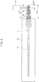
Fig. 1] Fig. 1 is a front view of an interdental cleaning instrument according to one embodiment of the present invention. - [
Fig. 2] Fig. 2 is a diagram schematically showing a state in which the shaft part is in a curved posture. - [
Fig. 3] Fig. 3 is a diagram schematically showing a method for measuring the first pressing force. - [
Fig. 4] Fig. 4 is a diagram schematically showing a method for measuring the second pressing force. - [
Fig. 5] Fig. 5 is a front view showing a modified example of the base part. - [
Fig. 6] Fig. 6 is a front view showing a modified example of the base part. - An
interdental cleaning instrument 1 according to one embodiment of the present invention will be described with reference toFigs. 1 to 6 . - The present
interdental cleaning instrument 1, as shown inFig. 1 , includes abase part 10 and acleaning part 20 composed of an elastomer having a hardness less than the hardness of thebase part 10. Thebase part 10 is preferably formed of a synthetic resin such as polypropylene, ABS, polybutylene terephthalate, a polycarbonate, polyethylene terephthalate, polystyrene, and a polyacetal. In the present embodiment, thebase part 10 is formed of polypropylene. As the elastomer, a styrene elastomer is used. However, a silicone, an olefin elastomer, a polyester elastomer or the like may be used as the elastomer. - The
base part 10 has a shape extending linearly along a specific direction (vertical direction inFig. 1 ). In the present embodiment, the dimension of thebase part 10 in the specific direction is set to 47.5 mm. Thebase part 10 has ashaft part 12 and agrip part 14. - The
shaft part 12 has a shape that can be inserted into an interdental space. Theshaft part 12 has aninsertion end section 12a formed at one end in the specific direction and abase end section 12b formed at the other end in the specific direction. Theshaft part 12 has such a shape that can be flexurally deformed so that theinsertion end section 12a is displaced in an axially perpendicular direction (lateral direction inFig. 1 ) that is perpendicular to the axial direction of theshaft part 12, with thebase end section 12b as a fulcrum. Theshaft part 12 has a shape that can be deformed at any point of anintermediate portion 12c located between theinsertion end section 12a and thebase end section 12b of theshaft part 12 so as to allow the displacement of theinsertion end section 12a at least between a steady-state posture (posture shown inFig. 1 ) and a curved posture (posture shown inFig. 2 ). The steady-state posture is a posture of theshaft part 12 when no external force acts on theshaft part 12. The curved posture, as shown inFig. 2 , is a posture in which an angle θ between a first straight line L1 connecting the deformed point of theintermediate portion 12c and theinsertion end section 12a and a second straight line L2 connecting the deformed point of theintermediate portion 12c and thebase end section 12b is 90 degrees. Theshaft part 12 is also formed in a shape such that the maximum displacement portion in which the amount of displacement from an initial position of the center axis of theshaft part 12 before buckling of theshaft part 12, in the axially perpendicular direction is at a maximum when the buckling occurs in theshaft part 12 is located between a portion of theshaft part 12 which is spaced 1.0 mm apart from theinsertion end section 12a toward thebase end section 12b side and a portion of theshaft part 12 which is spaced 9.0 mm apart from theinsertion end section 12a toward thebase end section 12b side. In the present embodiment, theshaft part 12 is formed in a substantially cylindrical shape. Specifically, theshaft part 12 is formed in a shape such that the outer diameter of theshaft part 12 gradually and slightly reduces from thebase end section 12b toward theinsertion end section 12a. In the present embodiment, the diameter of thebase end section 12b is set to 1.1 mm and the diameter of theinsertion end section 12a is set to 0.55 mm. Further, the dimension of theshaft part 12 in the axial direction is set to 15 mm. The maximum displacement portion is located at a position spaced 6 mm apart from theinsertion end section 12a toward thebase end section 12b side in theshaft part 12. - The
grip part 14 has a shape that extends from thebase end section 12b in a direction apart from the shaft part 12 (downward inFig. 1 ) along the axial direction and that can be grasped with the fingers. The shape of thegrip part 14 is set such that buckling occurs in theshaft part 12 when a compressive load is applied to thebase part 10 from both sides in the axial direction. In the present embodiment, the dimension of thegrip part 14 in the axial direction is set to 32.5 mm. Thegrip part 14 has asupport part 14a that supports theshaft part 12, and a grip-part body 14b connected to thesupport part 14a. - The
support part 14a is connected to thebase end section 12b. Thesupport part 14a has a shape such that the dimension of thesupport part 14a in the axially perpendicular direction gradually increases with the distance from thebase end section 12b. In the present embodiment, thesupport part 14a has a shape such that the dimension of thesupport part 14a in the axially perpendicular direction gradually increases with the distance from thebase end section 12b and such that curves so as to be convex inward in the axially perpendicular direction. It is preferable that a dimension w2 of the connecting portion between thesupport part 14a and the grip-part body 14b in the axially perpendicular direction be set to 1 time or more and 25 times or less the dimension (outer diameter) w1 of thebase end section 12b in the same direction. In the present embodiment, the dimension w2 is set to 6.3 times the dimension w1, that is, to 6.93 mm. Further, a dimension h1 of thesupport part 14a in the axial direction is set to 19 mm. - The grip-
part body 14b is formed in a rectangular shape. In the present embodiment, the dimension of the grip-part body 14b in the axially perpendicular direction is set to be the same as the dimension w2, and a dimension h2 of the grip-part body 14b in the axial direction is set to 13.5 mm. Further, this shape of the grip-part body 14b is not limiting. - The cleaning
part 20 has a shape that covers a portion of theshaft part 12, the portion including theinsertion end section 12a and having a dimension equal to or smaller than the dimension of theshaft part 12 in the axial direction, and is capable of cleaning an interdental space. In the present embodiment, the cleaningpart 20 has a shape covering the entire outer peripheral surface of theshaft part 12. Thus, the cleaningpart 20 has a shape covering the maximum displacement portion. The cleaningpart 20 has a cleaning-part body 22 and a plurality of brush bristles 24. - The cleaning-
part body 22 has a shape covering the entire outer peripheral surface of theshaft part 12. The cleaning-part body 22 has a cylindrical outer peripheral surface. The thickness of the cleaning-part body 22 is set to be smaller than the diameter of theshaft part 12. - Each brush bristle 24 is integrally formed with the cleaning-
part body 22 of the same material, protrudes outward in the axially perpendicular direction from the outer peripheral surface of the cleaning-part body 22, and has a shape such that the outer shape of the brush bristles 24 gradually decreases with the distance from the outer peripheral surface of the cleaning-part body 22. In the present embodiment, each brush bristle 24 is formed in a conical shape. - In the present embodiment, the shape of the
base part 10 is set such that a first pressing force corresponding to the strength of a tip-side portion 1a (seeFig. 3 ) of thebase part 10 which is located relatively close to theinsertion end section 12a is 0.3 N or more and 1.4 N or less and a second pressing force corresponding to the strength of a grip part-side portion 1b (seeFig. 4 ) of thebase part 10 which is located relatively far from theinsertion end section 12a is 0.5 N or more and 2.5 N or less. It is more preferable that the shape of thebase part 10 be set so that the first pressing force is 0.5 N or more and 1.4 N or less and the second pressing force is 0.80 N or more and 2.5 N or less. In the present embodiment, the shape of thebase part 10 is set such that the first pressing force is 1.3 N and the second pressing force is 1.4 N. - The first pressing force is a force required to press a portion spaced 2.5 mm apart from the tip of the cleaning
part 20 in theinterdental cleaning instrument 1 to thegrip part 14 side in 10 mm vertically downward in a state in which a portion spaced 10 mm apart from the tip of the cleaningpart 20 in theinterdental cleaning instrument 1 to thegrip part 14 side is fixed in a posture in which the axial direction is parallel to the horizontal direction. In other words, the tip-side portion 1a corresponds to a portion between the portion of spaced 2.5 mm apart from the tip of theinterdental cleaning instrument 1 and the portion spaced 10 mm apart from the tip. Therefore, the strength (first pressing force) of the tip-side portion 1a can be adjusted by the shape of the portion between the portion of thebase part 10 spaced 2.5 mm apart from the tip and the portion spaced 10 mm apart from the tip, that is, mainly by the shape of theshaft part 12. In the present embodiment, theshaft part 12 is formed in a substantially cylindrical shape. The diameter of theinsertion end section 12a is set to 0.55 mm, the diameter of thebase end section 12b is set to 1.1 mm, and the dimension of theshaft part 12 in the axial direction is set to 15 mm. - The second pressing force is a force required to press a portion spaced 8.0 mm apart from the tip of the cleaning
part 20 in theinterdental cleaning instrument 1 to thegrip part 14 side in 10 mm vertically downward in a state in which a portion spaced 35 mm apart from the tip of the cleaningpart 20 in theinterdental cleaning instrument 1 to thegrip part 14 side is fixed in a posture in which the axial direction is parallel to the horizontal direction. In other words, the grip part-side portion 1b corresponds to a portion between the portion spaced 8.0 mm apart from the tip of theinterdental cleaning instrument 1 and the portion spaced 35 mm apart from the tip. Therefore, the strength (second pressing force) of the grip part-side portion 1b can be adjusted by the shape of the portion between the portion of thebase part 10 spaced 8.0 mm apart from the tip and the portion spaced 35 mm apart from the tip, that is, mainly by the shape of thesupport part 14a. In the present embodiment, thesupport part 14a has a shape such that the dimension of thesupport part 14a in the axially perpendicular direction gradually increases with the distance from thebase end section 12b and such that curves so as to be convex inward in the axially perpendicular direction. Further, the dimension h1 of thesupport part 14a in the axial direction is set to 19 mm, and the dimension w2 of the connecting portion between thesupport part 14a and the grip-part body 14b in the axially perpendicular direction is set to 6.3 times the dimension (outer diameter) w1 of thebase end section 12b in the same direction. - As shown in
Figs. 3 and4 , the first pressing force and the second pressing force are measured using a fixinginstrument 32 capable of fixing theinterdental cleaning instrument 1 in a posture in which the axial direction is horizontal, and a pressingforce measuring part 34 capable of measuring the pressing force when pressing theinterdental cleaning instrument 1. - First, a method for measuring the first pressing force will be described with reference to
Fig. 3 . - First, as shown in
Fig. 3 , theinterdental cleaning instrument 1 is fixed to the fixinginstrument 32 in a posture in which the axial direction (the direction connecting theshaft part 12 and the grip part 14) is horizontal. Specifically, in the posture in which the axial direction is parallel to the horizontal direction, the entire portion of theinterdental cleaning instrument 1 that is separated from the tip of the cleaningpart 20 by 10 mm or more toward thegrip part 14 side is fixed to the fixinginstrument 32. - Next, the pressing
force measuring part 34 presses down aportion 2a (the tip part of the tip-side portion 1a) that is spaced 2.5 mm apart from the tip of the cleaningpart 20 to thegrip part 14 side of theinterdental cleaning instrument 1. The pressing is done in a vertically downward reach of 10 mm. Specifically, the pressingforce measuring part 34 is displaced for a vertically downward pressing in 10 mm from a state in which the pressingforce measuring part 34 is in contact with theportion 2a. The pressingforce measuring part 34 causes the tip-side portion 1a bearing theportion 2a to bend with the vertically downward pressing in 10 mm. The pressingforce measuring part 34 measures a pressing force in this process, that is, the first pressing force. In the present embodiment, the first pressing force is 1.3 N. - A method for measuring the second pressing force will be described hereinbelow with reference to
Fig. 4 . This measuring method is the same as the method for measuring the first pressing force, except for the fixing location of theinterdental cleaning instrument 1 with the fixinginstrument 32 and the pressing location of theinterdental cleaning instrument 1 with the pressingforce measuring part 34. - Thus, in the posture in which the axial direction is parallel to the horizontal direction, the entire portion of the
interdental cleaning instrument 1 that is spaced 35 mm or more apart from the tip of the cleaningpart 20 toward thegrip part 14 side is fixed to the fixinginstrument 32. In this state, aportion 2b (the tip part of the grip part-side portion 1b) spaced 8.0 mm apart from the tip of the cleaningpart 20 to thegrip part 14 side in theinterdental cleaning instrument 1 is pressed 10 mm vertically downward by the pressingforce measuring part 34. Then, the pressing force at this time, that is, the second pressing force is measured by the pressingforce measuring part 34. In the present embodiment, this second pressing force is 1.4 N. - The case where the space between the back teeth is cleaned with the
interdental cleaning instrument 1 described above will be described hereinbelow. - The
interdental cleaning instrument 1 is inserted into the oral cavity from the front teeth side towards the back teeth side with the cleaningpart 20 as a head. Here, since the space between the back teeth extends in a direction intersecting the direction from the front teeth side to the back teeth side in the oral cavity, where the cleaningpart 20 is inserted along the direction from the front teeth side to the back teeth side, the tip of the cleaningpart 20 comes into contact with the outer surface of the back teeth. - Then, in the state in which the tip of the cleaning
part 20 is in contact with the outer surface of the back teeth, thebase part 10 is further inserted in the present posture thereof toward the back of the oral cavity. In theinterdental cleaning instrument 1 of the present embodiment, the shape of thebase part 10 is set such that the first pressing force corresponding to the strength of the tip-side portion 1a is 1.3 N and the second pressing force corresponding to the strength of the grip part-side portion 1b is 1.4 N. Therefore, the insertion of the cleaningpart 20 into the space between the back teeth is facilitated. Specifically, as a result of setting the shape of thebase part 10 so that the first pressing force is 0.3 N or more, the strength of the tip-side portion 1a is sufficiently ensured. Therefore, when thebase part 10 is further inserted in the present posture thereof toward the back of the oral cavity from the state in which the tip of the cleaningpart 20 is in contact with the outer surface of the back teeth, the tip-side portion 1a is effectively flexurally deformed toward the back of the interdental space. Meanwhile, as a result of setting the shape of thebase part 10 so that the first pressing force is 1.4 or less, it is possible to suppress the inadequate deformation (impairment of insertability of the cleaningpart 20 into the back of the interdental space) of the tip-side portion 1a when thebase part 10 is further inserted in the present posture thereof toward the back of the oral cavity from the state in which the tip-side portion 1a is in contact with the outer surface of the back teeth. Further, as a result of setting the shape of thebase part 10 so that the second pressing force is 0.5 N or more, the tip-side portion 1a is effectively supported by the grip part-side portion 1b so as to allow for flexural deformation of the tip-side portion 1a. - Then, the
base part 10 is further inserted in the present posture thereof toward the back of the oral cavity from the state in which the tip of the cleaningpart 20 is inserted in the space between the back teeth. As a result, the angle formed by the first straight line L1 and the second straight line L2 is about 90 degrees, and the cleaningpart 20 is inserted deep into the space between the back teeth while theshaft part 12 is deformed so that the intersection point of the straight lines L1 and L2 is displaced from theinsertion end section 12a side toward thebase end section 12b side. In the presentinterdental cleaning instrument 1, theshaft part 12 has a shape deformable at any point of theintermediate portion 12c so as to allow for the displacement of theinsertion end section 12a between the steady posture and the curved posture. Therefore, it is possible to insert the cleaningpart 20 to the back of the space between the back teeth while suppressing the breakage of theshaft part 12. Further, since the shape of thebase part 10 is set such that the second pressing force is 0.5 N or more, the elastic restoring force of thebase part 10 during the insertion of the cleaningpart 20 in the space between the back teeth (the force pressing thecleaning part 20 against the outer surface of the back teeth), that is, the cleaning property of the interdental space or the back teeth is sufficiently ensured. Furthermore, since the shape of thebase part 10 is set such that the second pressing force is 2.5 N or less, the elastic restoring force of thebase part 10 is prevented from becoming too large. For this reason, the cleaningpart 20 is easily inserted to the back of the space between the back teeth, thereby effectively cleaning the interdental space or the back teeth. - Further, the cleaning
part 20 has a shape covering the maximum displacement portion of theshaft part 12. Therefore, even when theshaft part 12 is broken at the maximum displacement portion as a result of buckling of theshaft part 12 during cleaning of the interdental space, the portion of theshaft part 12 between the maximum displacement portion and theinsertion end section 12a is prevented from being detached from other portions of thebase part 10. Thus, even when buckling occurs in theshaft part 12 during the cleaning of the interdental space, a part of theshaft part 12 is prevented from remaining in the oral cavity. - This is not limited to the case where the shape of the
base part 10 is set such that the first pressing force and the second pressing force fall within the above ranges. Thus, the problem that a part of theshaft part 12 remains in the oral cavity when buckling occurs in theshaft part 12 during the cleaning of the interdental space can arise irrespective of the value of the first pressing force and the value of the second pressing force. By contrast, the above problem can be solved by setting the shape of thegrip part 14 so that buckling occurs in theshaft part 12 when a compressive load is applied to thebase part 10 from both sides in the axial direction, and by forming the cleaningpart 20 in a shape that covers the maximum displacement portion. - Further, the
shaft part 12 is formed in a shape such that the maximum displacement portion is located at a distance of 6 mm from theinsertion end section 12a toward thebase end section 12b side. Therefore, even when theshaft part 12 is buckled during cleaning of the interdental space, the teeth can be cleaned by the portion of the cleaningpart 20 that covers the portion of theshaft part 12 between the maximum displacement portion and theinsertion end section 12a. - It is to be understood that the presently disclosed embodiment is exemplary rather than restrictive in all the aspects thereof. The scope of the present invention is represented by the claims, rather than by the description of the embodiment described hereinabove, and is inclusive of meanings and scopes equivalent to those of the claims.
- The shape of the
base part 10 is not limited to the abovementioned example. The shape of thebase part 10 can be changed variously within a range where the condition of the first pressing force being 0.3 N or more and 1.4 N or less and the second pressing force being 0.5 N or more and 2.5 N or less is fulfilled. For example, as shown inFig. 5 , the shape of thegrip part 14 may be set so that the dimension h1 of thesupport part 14a in the axial direction is 17 mm and the dimension h2 of the grip-part body 14b in the axial direction is 15.5 mm. In this example, the radius of curvature of the outer end portion of thesupport part 14a in the axially perpendicular direction is larger than that in the embodiment. Alternatively, as shown inFig. 6 , the dimension h1 of thesupport part 14a in the axial direction and the dimension h2 of the grip-part body 14b in the axial direction may be set to be the same as those in the embodiment, and the shape of the grip part 14 (support part 14a) may be set so that the radius of curvature of the outer end portion of thesupport part 14a in the axially perpendicular direction is less than that in the embodiment. - Further, the first pressing force and the second pressing force can also be adjusted by the synthetic resin constituting the
base part 10. In addition, the first pressing force and the second pressing force may be adjusted by covering thegrip part 14 with the elastomer. Examples - Five examples of the
interdental cleaning instrument 1 of the above embodiment were fabricated, and an evaluation test on the insertability into the space between the back teeth and the cleaning property between the teeth was performed. - Example 1 is the
interdental cleaning instrument 1 of the above embodiment. In Example 2, in theinterdental cleaning instrument 1 shown inFig. 5 , thegrip part 14 is also covered with the styrene elastomer. Example 3 is theinterdental cleaning instrument 1 shown inFig. 6 . In these Examples 1 to 3, thebase part 10 was formed of polypropylene, and the cleaningpart 20 was formed of a styrene elastomer having a Shore A hardness of A40. - Example 4 is an instrument of the same shape as the
interdental cleaning instrument 1 shown inFig. 6 ; in this instrument, thebase part 10 is formed of an ABS resin and the cleaningpart 20 is formed of a styrene elastomer having a Shore A hardness of A40. Example 5 is an instrument of the same shape as theinterdental cleaning instrument 1 shown inFig. 6 ; in this instrument, thebase part 10 is formed of a polybutylene terephthalate (PBT) resin and the cleaningpart 20 is formed of a silicone having a Shore A hardness of A40. - The test results of each example are shown in Table 1.
[Table 1] First pressing force [N] Second pressing force [N] Insertability into interdental space Cleaning property of back teeth Example 1 1.3 1.4 ⊗ ⊗ Example 2 0.5 2.2 ⊗ ⊗ Example 3 1.4 0.8 ○ ○ Example 4 1 0.5 Δ Δ Example 5 0.3 1.1 Δ ○ - The interdental cleaning instruments were actually used by five test subjects, and the insertability into the space between the back teeth and the cleaning property between the teeth were evaluated. The evaluation was performed by conducting a questionnaire-based survey according to Visual Analogue Scale with scores between 0 and 3 points according to the following criteria. The evaluation results are summarized by rounding off the first decimal place of the questionnaire result.
-
- 0 points: difficult to insert
- 3 points: easy to insert
- <Cleaning property>
- 0 points: low cleaning effect
- 3 points: high cleaning effect
- In the table, the results with a total point score of 13 to 15 for five people are displayed as "⊗", those with 10 to 12 as "O", and those with 5 to 9 as "Δ".
- According to the test results, it is clear that because both the condition that the first pressing force is 0.3 N or more and 1.4 N or less and the condition that the second pressing force is 0.5 N or more and 2.5 N or less are satisfied in each example, the insertability and the cleaning property are good. Further, the results of Examples 3 to 5 also indicate that the first pressing force and the second pressing force can be adjusted also by the synthetic resin constituting the
base part 10. - In Example 4, although the first pressing force is 1 N, since the second pressing force is 0.5 N, that is, the strength of the grip part-
side portion 1b is somewhat low, the insertability and the cleaning property are both evaluated as "Δ". - In Example 5, although the cleaning property is high because the second pressing force is 1.1 N, since the first pressing force is 0.3 N, that is, the strength of the tip-
side portion 1a is somewhat low, the evaluation of the insertability is "Δ". - Although the results are not shown, when the first pressing force exceeded 1.4 N, the total point score of the evaluation of at least the insertability into the interdental space became 4 or less, when the second pressing force was less than 0.3 N, the total point score of the evaluation of both the insertability into the interdental space and the cleaning property became 4 or less, and when the second pressing force exceeded 2.5 N, the total point score of the evaluation of at least the insertability into the interdental space was 4 or less.
- Here, the above embodiment will be outlined.
- The interdental cleaning instrument of the present embodiment includes: a base part having a shape extending in a specific direction; and a cleaning part that is composed of an elastomer having a hardness lower than the hardness of the base part, covers at least a portion of the base part, and is capable of cleaning an interdental space, wherein the base part has a shaft part which has a shape that allows to be inserted in the interdental space, and has an insertion end section formed at one end in the specific direction and a base end section formed at the other end in the specific direction, and a grip part that extends from the base end section along the specific direction so as to be spaced apart from the shaft part and has a shape that can be grasped by fingers; the shaft part has a shape that can be flexurally deformed so as to allow for a displacement of the insertion end section in an axially perpendicular direction, which is perpendicular to an axial direction of the shaft part, with respect to the base end section; the cleaning part has a shape that covers a portion of the shaft part, the portion including the insertion end section and having a dimension equal to or less than a dimension of the shaft part in the axial direction; a dimension of the base part in the axial direction is set to 35 mm or more; and at least the shape of the base part is set such that a first pressing force required to press a portion spaced 2.5 mm apart from a tip of the cleaning part in the interdental cleaning instrument to the grip part side in 10 mm vertically downward is 0.3 N or more and 1.4 N or less in a state in which a portion spaced 10 mm apart from the tip of the cleaning part in the interdental cleaning instrument to the grip part side is fixed in a posture in which the axial direction is parallel to a horizontal direction, and a second pressing force required to press a portion spaced 8.0 mm apart from the tip of the cleaning part in the interdental cleaning instrument to the grip part side in 10 mm vertically downward is 0.5 N or more and 2.5 N or less in a state in which a portion spaced 35 mm apart from the tip of the cleaning part in the interdental cleaning instrument to the grip part side is fixed in a posture in which the axial direction is parallel to a horizontal direction.
- In the present interdental cleaning instrument, the shape of the base part is set such that the first pressing force corresponding to the strength of the tip-side portion of the base part which is located relatively close to the insertion end section is 0.3 N or more and 1.4 N or less and the second pressing force corresponding to the strength of the grip part-side portion of the base part which is located relatively far from the insertion end section is 0.5 N or more. Therefore, the insertion of the cleaning part into the space between the back teeth is facilitated. Furthermore, since the shape of the base part is set such that the second pressing force is 2.5 N or less, the interdental space is effectively cleaned by the cleaning part during the insertion of the cleaning part into the interdental space. Specifically, as a result of setting the shape of the base part so that the first pressing force is 0.3 N or more, the strength of the tip-side portion is sufficiently ensured so that the tip-side portion is effectively flexurally deformed toward the back of the interdental space when the base part is further inserted in the present posture thereof toward the back of the oral cavity from the state in which the tip of the cleaning part is in contact with the outer surface of the back teeth. Meanwhile, as a result of setting the shape of the base part so that the first pressing force is 1.4 or less, it is possible to suppress the inadequate deformation (impairment of insertability of the cleaning part into the back of the interdental space) when the base part is further inserted in the present posture thereof toward the back of the oral cavity from the state in which the tip-side portion is in contact with the outer surface of the back teeth. Further, as a result of setting the shape of the base part so that the second pressing force is 0.5 N or more, the tip-side portion is effectively supported by the grip part-side portion so as to allow for flexural deformation of the tip-side portion, and the elastic restoring force of the base part during the insertion of the cleaning part in the space between the back teeth (the force pressing the cleaning part against the outer surface of the back teeth), that is, the cleaning property of the interdental space or the back teeth is sufficiently ensured. Furthermore, since the shape of the base part is set such that the second pressing force is 2.5 N or less, the elastic restoring force of the base part is prevented from becoming too large. Therefore, the cleaning part is easily inserted to the back of the space between the back teeth, thereby effectively cleaning the interdental space or the back teeth.
- In this case, it is preferred that the shaft part have a shape that can be deformed at any point of an intermediate portion located between the insertion end section and the base end section of the shaft part so as to allow the displacement of the insertion end section at least between the steady-state posture in which no external force acts on the shaft part and the curved posture in which the angle between the first straight line connecting the deformed point of the intermediate portion and the insertion end section and the second straight line connecting the deformed point of the intermediate portion and the base end section is 90 degrees.
- In this way, when the base part is further inserted in the present posture thereof toward the back of the oral cavity from the state in which the tip of the cleaning part is in contact with the outer surface of the back teeth, breakage of the shaft part is suppressed. Therefore, the insertion of the base part makes it possible to insert the cleaning part to the back of the space between the back teeth. Specifically, when the cleaning part is further inserted into the space between the back teeth from the state in which the tip of the cleaning part is in contact with the outer surface of the back teeth, since the angle formed by the first straight line and the second straight line is about 90 degrees, by setting the shape of the shaft part to be deformable so as to allow the displacement of the insertion end section between the steady-state posture and the curved posture at any point of the intermediate portion, it is possible to insert the cleaning part to the back of the space between the back teeth while suppressing the breakage of the shaft part.
- Further, in the present cleaning instrument, it is preferred that the shape of the grip part be set such that buckling occurs in the shaft part when a compressive load is applied to the base part from both sides in the axial direction, and the cleaning part have a shape that covers the maximum displacement portion of the shaft part in which the amount of displacement from an initial position of the center axis of the shaft part before buckling of the shaft part, in the axially perpendicular direction is at a maximum when the buckling occurs in the shaft part.
- In this way, even when the shaft part is broken at the maximum displacement portion as a result of buckling of the shaft part during cleaning of the interdental space, since the maximum displacement portion is covered by the cleaning part, the portion of the shaft part between the maximum displacement portion and the insertion end section is prevented from being detached from other portions of the base part. Thus, even when buckling occurs in the shaft part during the cleaning of the interdental space, a part of the shaft part is prevented from remaining in the oral cavity.
- In this case, it is preferred that the shaft part be formed in shape such that the maximum displacement portion is located between a portion of the shaft part which is spaced 1.0 mm apart from the insertion end section toward the base end section side and a portion of the shaft part which is spaced 9.0 mm apart from the insertion end section toward the base end section side.
- In this way, even when buckling occurs in the shaft part during cleaning of the interdental space, the interdental space can be cleaned by the portion of the cleaning part that covers the portion between the maximum displacement portion and the insertion end section in the shaft part.
Claims (4)
- An interdental cleaning instrument comprising:a base part having a shape extending in a specific direction; anda cleaning part that is composed of an elastomer having a hardness lower than the hardness of the base part, covers at least a portion of the base part, and is capable of cleaning an interdental space, whereinthe base part has a shaft part which has a shape that allows to be inserted in the interdental space, and has an insertion end section formed at one end in the specific direction and a base end section formed at the other end in the specific direction, and a grip part that extends from the base end section along the specific direction so as to be spaced apart from the shaft part and has a shape that can be grasped by fingers;the shaft part has a shape that can be flexurally deformed so as to allow for a displacement of the insertion end section in an axially perpendicular direction, which is perpendicular to an axial direction of the shaft part, with respect to the base end section;the cleaning part has a shape that covers a portion of the shaft part, the portion including the insertion end section and having a dimension equal to or less than a dimension of the shaft part in the axial direction;a dimension of the base part in the axial direction is set to 35 mm or more; andat least the shape of the base part is set such that a first pressing force required to press a portion spaced 2.5 mm apart from a tip of the cleaning part in the interdental cleaning instrument to the grip part side in 10 mm vertically downward is 0.3 N or more and 1.4 N or less in a state in which a portion spaced 10 mm apart from the tip of the cleaning part in the interdental cleaning instrument to the grip part side is fixed in a posture in which the axial direction is parallel to a horizontal direction, and a second pressing force required to press a portion spaced 8.0 mm apart from the tip of the cleaning part in the interdental cleaning instrument to the grip part side in 10 mm vertically downward is 0.5 N or more and 2.5 N or less in a state in which a portion spaced 35 mm apart from the tip of the cleaning part in the interdental cleaning instrument to the grip part side is fixed in a posture in which the axial direction is parallel to a horizontal direction.
- The interdental cleaning instrument according to claim 1, wherein
the shaft part has a shape that can be deformed at any point of an intermediate portion located between the insertion end section and the base end section of the shaft part so as to allow a displacement of the insertion end section at least between a steady-state posture in which no external force acts on the shaft part and a curved posture in which an angle between a first straight line connecting the deformed point of the intermediate portion and the insertion end section and a second straight line connecting the deformed portion of the intermediate portion and the base end section is 90 degrees. - The interdental cleaning instrument according to claim 1 or 2, wherein
the shape of the grip part is set such that buckling occurs in the shaft part when a compressive load is applied to the base part from both sides in the axial direction; and
the cleaning part has a shape that covers a maximum displacement portion of the shaft part in which an amount of displacement from an initial position of a center axis of the shaft part before buckling of the shaft part, in the axially perpendicular direction is at a maximum when the buckling occurs in the shaft part. - The interdental cleaning instrument according to claim 3, wherein
the shaft part is formed in a shape such that the maximum displacement portion is located between a portion of the shaft part which is spaced 1.0 mm apart from the insertion end section toward the base end section side and a portion of the shaft part which is spaced 9.0 mm apart from the insertion end section toward the base end section side.
Applications Claiming Priority (2)
| Application Number | Priority Date | Filing Date | Title |
|---|---|---|---|
| JP2015006487A JP5977382B2 (en) | 2015-01-16 | 2015-01-16 | Interdental cleaning tool |
| PCT/JP2015/068407 WO2016113928A1 (en) | 2015-01-16 | 2015-06-25 | Interdental cleaning instrument |
Publications (3)
| Publication Number | Publication Date |
|---|---|
| EP3245977A1 true EP3245977A1 (en) | 2017-11-22 |
| EP3245977A4 EP3245977A4 (en) | 2018-08-29 |
| EP3245977B1 EP3245977B1 (en) | 2019-07-24 |
Family
ID=56405487
Family Applications (1)
| Application Number | Title | Priority Date | Filing Date |
|---|---|---|---|
| EP15877880.3A Active EP3245977B1 (en) | 2015-01-16 | 2015-06-25 | Interdental cleaning instrument |
Country Status (5)
| Country | Link |
|---|---|
| US (1) | US11026771B2 (en) |
| EP (1) | EP3245977B1 (en) |
| JP (1) | JP5977382B2 (en) |
| CN (1) | CN107205802B (en) |
| WO (1) | WO2016113928A1 (en) |
Cited By (2)
| Publication number | Priority date | Publication date | Assignee | Title |
|---|---|---|---|---|
| DE102018002147B3 (en) | 2018-03-16 | 2019-06-13 | Interbros Gmbh | Interdental cleaner |
| EP3782582A4 (en) * | 2018-04-27 | 2021-06-23 | Kobayashi Pharmaceutical Co., Ltd. | Interdental cleaning tool |
Families Citing this family (7)
| Publication number | Priority date | Publication date | Assignee | Title |
|---|---|---|---|---|
| USD767900S1 (en) * | 2015-03-03 | 2016-10-04 | LeedTech Resources Company, LLC | Interdental brush |
| JP6774280B2 (en) * | 2016-09-15 | 2020-10-21 | 小林製薬株式会社 | Interdental cleaning tool housing |
| JP7066323B2 (en) * | 2017-02-28 | 2022-05-13 | 小林製薬株式会社 | Intertooth cleaning tool |
| EP3684221A1 (en) | 2017-09-19 | 2020-07-29 | Trisa Holding AG | Applicator device |
| JP7449038B2 (en) * | 2018-06-29 | 2024-03-13 | 小林製薬株式会社 | Interdental cleaning tool |
| JP2020103850A (en) * | 2018-12-28 | 2020-07-09 | 小林製薬株式会社 | Interdental cleaning tool |
| JP7417353B2 (en) | 2018-12-28 | 2024-01-18 | 小林製薬株式会社 | Manufacturing method for interdental cleaning tools |
Family Cites Families (18)
| Publication number | Priority date | Publication date | Assignee | Title |
|---|---|---|---|---|
| JPS61180014U (en) * | 1985-03-07 | 1986-11-10 | ||
| JP3002668B1 (en) * | 1998-07-14 | 2000-01-24 | 株式会社広栄社 | Brush toothpick |
| JP3824041B2 (en) * | 1998-12-04 | 2006-09-20 | 株式会社三▲しゅう▼プレシジョン | Interdental cleaning tool and manufacturing method thereof |
| US6082999A (en) * | 1999-07-27 | 2000-07-04 | Tcherny; Iosif | Interdental device and container |
| US20140075698A1 (en) * | 2004-03-19 | 2014-03-20 | Wai-Kuen Lui | Flexible interdental brush applicator and interdental gum stimulator |
| TWI653971B (en) * | 2012-05-24 | 2019-03-21 | 瑞士商新時代舒意適Sa協會 | Interdental sweeper |
| EP4098147A1 (en) * | 2012-07-02 | 2022-12-07 | Trisa Holding AG | Interdental brush |
| WO2014065368A1 (en) * | 2012-10-24 | 2014-05-01 | サンスター株式会社 | Interdental cleaning tool |
| DE102012025039B4 (en) * | 2012-12-20 | 2015-02-19 | Zahoransky Formenbau Gmbh | Process for the production of injection molded parts in two-component injection molding technology as well as injection molded part |
| KR101520433B1 (en) * | 2013-07-08 | 2015-05-14 | 주식회사 레이언스 | Image sensor and manufacturing method thereof |
| DE102014001503A1 (en) * | 2014-02-06 | 2015-08-06 | Pheneo Gmbh | Interdental brush for cleaning interdental spaces and / or dental implants |
| EP2829253B1 (en) * | 2014-03-06 | 2016-10-12 | Tepe Munhygienprodukter AB | Interdental cleaner |
| JP6265262B2 (en) * | 2014-03-27 | 2018-01-24 | サンスター スイス エスエー | Interdental cleaning tool and manufacturing method thereof |
| GB2528886B (en) * | 2014-08-01 | 2019-04-03 | Wisdom Toothbrushes Ltd | Flexible interdental cleaning device |
| CN107106273A (en) * | 2014-11-11 | 2017-08-29 | 太阳星光齿磨公司 | Teeth space burnisher |
| JP6547830B2 (en) * | 2015-06-08 | 2019-07-24 | サンスター スイス エスエー | Interdental cleaning tool |
| JP1600695S (en) * | 2016-07-14 | 2018-03-26 | ||
| JP2019118516A (en) * | 2017-12-28 | 2019-07-22 | 小林製薬株式会社 | Interdental cleaning tool |
-
2015
- 2015-01-16 JP JP2015006487A patent/JP5977382B2/en not_active Ceased
- 2015-06-25 US US15/542,501 patent/US11026771B2/en active Active
- 2015-06-25 WO PCT/JP2015/068407 patent/WO2016113928A1/en active Application Filing
- 2015-06-25 CN CN201580074005.1A patent/CN107205802B/en active Active
- 2015-06-25 EP EP15877880.3A patent/EP3245977B1/en active Active
Cited By (4)
| Publication number | Priority date | Publication date | Assignee | Title |
|---|---|---|---|---|
| DE102018002147B3 (en) | 2018-03-16 | 2019-06-13 | Interbros Gmbh | Interdental cleaner |
| WO2019174782A1 (en) | 2018-03-16 | 2019-09-19 | Interbros Gmbh | Interdental cleaner |
| EP3782582A4 (en) * | 2018-04-27 | 2021-06-23 | Kobayashi Pharmaceutical Co., Ltd. | Interdental cleaning tool |
| US11986086B2 (en) | 2018-04-27 | 2024-05-21 | Kobayashi Pharmaceutical Co., Ltd. | Interdental cleaning tool |
Also Published As
| Publication number | Publication date |
|---|---|
| EP3245977A4 (en) | 2018-08-29 |
| CN107205802A (en) | 2017-09-26 |
| WO2016113928A1 (en) | 2016-07-21 |
| JP2016131602A (en) | 2016-07-25 |
| JP5977382B2 (en) | 2016-08-24 |
| US11026771B2 (en) | 2021-06-08 |
| EP3245977B1 (en) | 2019-07-24 |
| CN107205802B (en) | 2019-09-03 |
| US20180263741A1 (en) | 2018-09-20 |
Similar Documents
| Publication | Publication Date | Title |
|---|---|---|
| EP3245977B1 (en) | Interdental cleaning instrument | |
| JP6311796B2 (en) | Interdental cleaning tool | |
| WO2017155039A1 (en) | Toothbrush | |
| KR102589498B1 (en) | interdental brush | |
| CN113995223B (en) | Toothbrush with tooth brush | |
| JP6594247B2 (en) | Interdental cleaning tool | |
| WO2016167191A1 (en) | Interdental brush | |
| WO2017155045A1 (en) | Toothbrush | |
| US11633269B2 (en) | Method of manufacturing inter-dental cleaning tool | |
| JP7066323B2 (en) | Intertooth cleaning tool | |
| EP3646814A1 (en) | Interdental cleaning tool | |
| JP2018126593A (en) | Interdental washing tool | |
| JP6595957B2 (en) | Cleaning tool | |
| CN107107124B (en) | Cleaning tool | |
| WO2020137251A1 (en) | Interdental cleaning tool | |
| EP3646813A1 (en) | Interdental cleaning tool | |
| WO2017018340A1 (en) | Toothbrush | |
| JP2021106725A (en) | Interdental cleaner | |
| JP2021106724A (en) | Interdental cleaning tool | |
| JP2024117546A (en) | Interdental brushes | |
| JP3155361U (en) | Flexible touch-sensitive earpick |
Legal Events
| Date | Code | Title | Description |
|---|---|---|---|
| STAA | Information on the status of an ep patent application or granted ep patent |
Free format text: STATUS: THE INTERNATIONAL PUBLICATION HAS BEEN MADE |
|
| PUAI | Public reference made under article 153(3) epc to a published international application that has entered the european phase |
Free format text: ORIGINAL CODE: 0009012 |
|
| STAA | Information on the status of an ep patent application or granted ep patent |
Free format text: STATUS: REQUEST FOR EXAMINATION WAS MADE |
|
| 17P | Request for examination filed |
Effective date: 20170720 |
|
| AK | Designated contracting states |
Kind code of ref document: A1 Designated state(s): AL AT BE BG CH CY CZ DE DK EE ES FI FR GB GR HR HU IE IS IT LI LT LU LV MC MK MT NL NO PL PT RO RS SE SI SK SM TR |
|
| AX | Request for extension of the european patent |
Extension state: BA ME |
|
| DAV | Request for validation of the european patent (deleted) | ||
| DAX | Request for extension of the european patent (deleted) | ||
| A4 | Supplementary search report drawn up and despatched |
Effective date: 20180727 |
|
| RIC1 | Information provided on ipc code assigned before grant |
Ipc: A61C 15/02 20060101AFI20180723BHEP |
|
| GRAP | Despatch of communication of intention to grant a patent |
Free format text: ORIGINAL CODE: EPIDOSNIGR1 |
|
| STAA | Information on the status of an ep patent application or granted ep patent |
Free format text: STATUS: GRANT OF PATENT IS INTENDED |
|
| INTG | Intention to grant announced |
Effective date: 20190320 |
|
| GRAS | Grant fee paid |
Free format text: ORIGINAL CODE: EPIDOSNIGR3 |
|
| GRAA | (expected) grant |
Free format text: ORIGINAL CODE: 0009210 |
|
| STAA | Information on the status of an ep patent application or granted ep patent |
Free format text: STATUS: THE PATENT HAS BEEN GRANTED |
|
| AK | Designated contracting states |
Kind code of ref document: B1 Designated state(s): AL AT BE BG CH CY CZ DE DK EE ES FI FR GB GR HR HU IE IS IT LI LT LU LV MC MK MT NL NO PL PT RO RS SE SI SK SM TR |
|
| REG | Reference to a national code |
Ref country code: GB Ref legal event code: FG4D |
|
| REG | Reference to a national code |
Ref country code: CH Ref legal event code: EP |
|
| REG | Reference to a national code |
Ref country code: DE Ref legal event code: R096 Ref document number: 602015034587 Country of ref document: DE |
|
| REG | Reference to a national code |
Ref country code: CH Ref legal event code: NV Representative=s name: VALIPAT S.A., CH Ref country code: AT Ref legal event code: REF Ref document number: 1157278 Country of ref document: AT Kind code of ref document: T Effective date: 20190815 |
|
| REG | Reference to a national code |
Ref country code: IE Ref legal event code: FG4D |
|
| REG | Reference to a national code |
Ref country code: CH Ref legal event code: NV Representative=s name: VALIPAT S.A. C/O BOVARD SA NEUCHATEL, CH |
|
| REG | Reference to a national code |
Ref country code: NL Ref legal event code: MP Effective date: 20190724 |
|
| REG | Reference to a national code |
Ref country code: LT Ref legal event code: MG4D |
|
| REG | Reference to a national code |
Ref country code: AT Ref legal event code: MK05 Ref document number: 1157278 Country of ref document: AT Kind code of ref document: T Effective date: 20190724 |
|
| PG25 | Lapsed in a contracting state [announced via postgrant information from national office to epo] |
Ref country code: FI Free format text: LAPSE BECAUSE OF FAILURE TO SUBMIT A TRANSLATION OF THE DESCRIPTION OR TO PAY THE FEE WITHIN THE PRESCRIBED TIME-LIMIT Effective date: 20190724 Ref country code: HR Free format text: LAPSE BECAUSE OF FAILURE TO SUBMIT A TRANSLATION OF THE DESCRIPTION OR TO PAY THE FEE WITHIN THE PRESCRIBED TIME-LIMIT Effective date: 20190724 Ref country code: PT Free format text: LAPSE BECAUSE OF FAILURE TO SUBMIT A TRANSLATION OF THE DESCRIPTION OR TO PAY THE FEE WITHIN THE PRESCRIBED TIME-LIMIT Effective date: 20191125 Ref country code: NL Free format text: LAPSE BECAUSE OF FAILURE TO SUBMIT A TRANSLATION OF THE DESCRIPTION OR TO PAY THE FEE WITHIN THE PRESCRIBED TIME-LIMIT Effective date: 20190724 Ref country code: LT Free format text: LAPSE BECAUSE OF FAILURE TO SUBMIT A TRANSLATION OF THE DESCRIPTION OR TO PAY THE FEE WITHIN THE PRESCRIBED TIME-LIMIT Effective date: 20190724 Ref country code: BG Free format text: LAPSE BECAUSE OF FAILURE TO SUBMIT A TRANSLATION OF THE DESCRIPTION OR TO PAY THE FEE WITHIN THE PRESCRIBED TIME-LIMIT Effective date: 20191024 Ref country code: NO Free format text: LAPSE BECAUSE OF FAILURE TO SUBMIT A TRANSLATION OF THE DESCRIPTION OR TO PAY THE FEE WITHIN THE PRESCRIBED TIME-LIMIT Effective date: 20191024 Ref country code: SE Free format text: LAPSE BECAUSE OF FAILURE TO SUBMIT A TRANSLATION OF THE DESCRIPTION OR TO PAY THE FEE WITHIN THE PRESCRIBED TIME-LIMIT Effective date: 20190724 Ref country code: AT Free format text: LAPSE BECAUSE OF FAILURE TO SUBMIT A TRANSLATION OF THE DESCRIPTION OR TO PAY THE FEE WITHIN THE PRESCRIBED TIME-LIMIT Effective date: 20190724 |
|
| PG25 | Lapsed in a contracting state [announced via postgrant information from national office to epo] |
Ref country code: IS Free format text: LAPSE BECAUSE OF FAILURE TO SUBMIT A TRANSLATION OF THE DESCRIPTION OR TO PAY THE FEE WITHIN THE PRESCRIBED TIME-LIMIT Effective date: 20191124 Ref country code: ES Free format text: LAPSE BECAUSE OF FAILURE TO SUBMIT A TRANSLATION OF THE DESCRIPTION OR TO PAY THE FEE WITHIN THE PRESCRIBED TIME-LIMIT Effective date: 20190724 Ref country code: AL Free format text: LAPSE BECAUSE OF FAILURE TO SUBMIT A TRANSLATION OF THE DESCRIPTION OR TO PAY THE FEE WITHIN THE PRESCRIBED TIME-LIMIT Effective date: 20190724 Ref country code: GR Free format text: LAPSE BECAUSE OF FAILURE TO SUBMIT A TRANSLATION OF THE DESCRIPTION OR TO PAY THE FEE WITHIN THE PRESCRIBED TIME-LIMIT Effective date: 20191025 Ref country code: RS Free format text: LAPSE BECAUSE OF FAILURE TO SUBMIT A TRANSLATION OF THE DESCRIPTION OR TO PAY THE FEE WITHIN THE PRESCRIBED TIME-LIMIT Effective date: 20190724 Ref country code: LV Free format text: LAPSE BECAUSE OF FAILURE TO SUBMIT A TRANSLATION OF THE DESCRIPTION OR TO PAY THE FEE WITHIN THE PRESCRIBED TIME-LIMIT Effective date: 20190724 |
|
| PG25 | Lapsed in a contracting state [announced via postgrant information from national office to epo] |
Ref country code: TR Free format text: LAPSE BECAUSE OF FAILURE TO SUBMIT A TRANSLATION OF THE DESCRIPTION OR TO PAY THE FEE WITHIN THE PRESCRIBED TIME-LIMIT Effective date: 20190724 |
|
| PG25 | Lapsed in a contracting state [announced via postgrant information from national office to epo] |
Ref country code: IT Free format text: LAPSE BECAUSE OF FAILURE TO SUBMIT A TRANSLATION OF THE DESCRIPTION OR TO PAY THE FEE WITHIN THE PRESCRIBED TIME-LIMIT Effective date: 20190724 Ref country code: RO Free format text: LAPSE BECAUSE OF FAILURE TO SUBMIT A TRANSLATION OF THE DESCRIPTION OR TO PAY THE FEE WITHIN THE PRESCRIBED TIME-LIMIT Effective date: 20190724 Ref country code: DK Free format text: LAPSE BECAUSE OF FAILURE TO SUBMIT A TRANSLATION OF THE DESCRIPTION OR TO PAY THE FEE WITHIN THE PRESCRIBED TIME-LIMIT Effective date: 20190724 Ref country code: EE Free format text: LAPSE BECAUSE OF FAILURE TO SUBMIT A TRANSLATION OF THE DESCRIPTION OR TO PAY THE FEE WITHIN THE PRESCRIBED TIME-LIMIT Effective date: 20190724 Ref country code: PL Free format text: LAPSE BECAUSE OF FAILURE TO SUBMIT A TRANSLATION OF THE DESCRIPTION OR TO PAY THE FEE WITHIN THE PRESCRIBED TIME-LIMIT Effective date: 20190724 |
|
| PG25 | Lapsed in a contracting state [announced via postgrant information from national office to epo] |
Ref country code: SM Free format text: LAPSE BECAUSE OF FAILURE TO SUBMIT A TRANSLATION OF THE DESCRIPTION OR TO PAY THE FEE WITHIN THE PRESCRIBED TIME-LIMIT Effective date: 20190724 Ref country code: IS Free format text: LAPSE BECAUSE OF FAILURE TO SUBMIT A TRANSLATION OF THE DESCRIPTION OR TO PAY THE FEE WITHIN THE PRESCRIBED TIME-LIMIT Effective date: 20200224 Ref country code: SK Free format text: LAPSE BECAUSE OF FAILURE TO SUBMIT A TRANSLATION OF THE DESCRIPTION OR TO PAY THE FEE WITHIN THE PRESCRIBED TIME-LIMIT Effective date: 20190724 Ref country code: CZ Free format text: LAPSE BECAUSE OF FAILURE TO SUBMIT A TRANSLATION OF THE DESCRIPTION OR TO PAY THE FEE WITHIN THE PRESCRIBED TIME-LIMIT Effective date: 20190724 |
|
| REG | Reference to a national code |
Ref country code: DE Ref legal event code: R097 Ref document number: 602015034587 Country of ref document: DE |
|
| PLBE | No opposition filed within time limit |
Free format text: ORIGINAL CODE: 0009261 |
|
| STAA | Information on the status of an ep patent application or granted ep patent |
Free format text: STATUS: NO OPPOSITION FILED WITHIN TIME LIMIT |
|
| PG2D | Information on lapse in contracting state deleted |
Ref country code: IS |
|
| 26N | No opposition filed |
Effective date: 20200603 |
|
| PG25 | Lapsed in a contracting state [announced via postgrant information from national office to epo] |
Ref country code: SI Free format text: LAPSE BECAUSE OF FAILURE TO SUBMIT A TRANSLATION OF THE DESCRIPTION OR TO PAY THE FEE WITHIN THE PRESCRIBED TIME-LIMIT Effective date: 20190724 |
|
| PG25 | Lapsed in a contracting state [announced via postgrant information from national office to epo] |
Ref country code: MC Free format text: LAPSE BECAUSE OF FAILURE TO SUBMIT A TRANSLATION OF THE DESCRIPTION OR TO PAY THE FEE WITHIN THE PRESCRIBED TIME-LIMIT Effective date: 20190724 |
|
| GBPC | Gb: european patent ceased through non-payment of renewal fee |
Effective date: 20200625 |
|
| PG25 | Lapsed in a contracting state [announced via postgrant information from national office to epo] |
Ref country code: LU Free format text: LAPSE BECAUSE OF NON-PAYMENT OF DUE FEES Effective date: 20200625 |
|
| REG | Reference to a national code |
Ref country code: BE Ref legal event code: MM Effective date: 20200630 |
|
| PG25 | Lapsed in a contracting state [announced via postgrant information from national office to epo] |
Ref country code: GB Free format text: LAPSE BECAUSE OF NON-PAYMENT OF DUE FEES Effective date: 20200625 Ref country code: IE Free format text: LAPSE BECAUSE OF NON-PAYMENT OF DUE FEES Effective date: 20200625 |
|
| PG25 | Lapsed in a contracting state [announced via postgrant information from national office to epo] |
Ref country code: BE Free format text: LAPSE BECAUSE OF NON-PAYMENT OF DUE FEES Effective date: 20200630 |
|
| PG25 | Lapsed in a contracting state [announced via postgrant information from national office to epo] |
Ref country code: MT Free format text: LAPSE BECAUSE OF FAILURE TO SUBMIT A TRANSLATION OF THE DESCRIPTION OR TO PAY THE FEE WITHIN THE PRESCRIBED TIME-LIMIT Effective date: 20190724 Ref country code: CY Free format text: LAPSE BECAUSE OF FAILURE TO SUBMIT A TRANSLATION OF THE DESCRIPTION OR TO PAY THE FEE WITHIN THE PRESCRIBED TIME-LIMIT Effective date: 20190724 |
|
| PG25 | Lapsed in a contracting state [announced via postgrant information from national office to epo] |
Ref country code: MK Free format text: LAPSE BECAUSE OF FAILURE TO SUBMIT A TRANSLATION OF THE DESCRIPTION OR TO PAY THE FEE WITHIN THE PRESCRIBED TIME-LIMIT Effective date: 20190724 |
|
| P01 | Opt-out of the competence of the unified patent court (upc) registered |
Effective date: 20230510 |
|
| PGFP | Annual fee paid to national office [announced via postgrant information from national office to epo] |
Ref country code: CH Payment date: 20230702 Year of fee payment: 9 |
|
| PGFP | Annual fee paid to national office [announced via postgrant information from national office to epo] |
Ref country code: DE Payment date: 20240619 Year of fee payment: 10 |
|
| PGFP | Annual fee paid to national office [announced via postgrant information from national office to epo] |
Ref country code: FR Payment date: 20240628 Year of fee payment: 10 |